EP2845982A2 - Pfosten für eine Schwenktür und Brandschutzverglasung mit einem solchen Pfosten - Google Patents
Pfosten für eine Schwenktür und Brandschutzverglasung mit einem solchen Pfosten Download PDFInfo
- Publication number
- EP2845982A2 EP2845982A2 EP20140184100 EP14184100A EP2845982A2 EP 2845982 A2 EP2845982 A2 EP 2845982A2 EP 20140184100 EP20140184100 EP 20140184100 EP 14184100 A EP14184100 A EP 14184100A EP 2845982 A2 EP2845982 A2 EP 2845982A2
- Authority
- EP
- European Patent Office
- Prior art keywords
- post
- fire
- door
- profiles
- profile
- Prior art date
- Legal status (The legal status is an assumption and is not a legal conclusion. Google has not performed a legal analysis and makes no representation as to the accuracy of the status listed.)
- Granted
Links
Images

Classifications
-
- E—FIXED CONSTRUCTIONS
- E06—DOORS, WINDOWS, SHUTTERS, OR ROLLER BLINDS IN GENERAL; LADDERS
- E06B—FIXED OR MOVABLE CLOSURES FOR OPENINGS IN BUILDINGS, VEHICLES, FENCES OR LIKE ENCLOSURES IN GENERAL, e.g. DOORS, WINDOWS, BLINDS, GATES
- E06B5/00—Doors, windows, or like closures for special purposes; Border constructions therefor
- E06B5/10—Doors, windows, or like closures for special purposes; Border constructions therefor for protection against air-raid or other war-like action; for other protective purposes
- E06B5/16—Fireproof doors or similar closures; Adaptations of fixed constructions therefor
- E06B5/161—Profile members therefor
-
- E—FIXED CONSTRUCTIONS
- E06—DOORS, WINDOWS, SHUTTERS, OR ROLLER BLINDS IN GENERAL; LADDERS
- E06B—FIXED OR MOVABLE CLOSURES FOR OPENINGS IN BUILDINGS, VEHICLES, FENCES OR LIKE ENCLOSURES IN GENERAL, e.g. DOORS, WINDOWS, BLINDS, GATES
- E06B3/00—Window sashes, door leaves, or like elements for closing wall or like openings; Layout of fixed or moving closures, e.g. windows in wall or like openings; Features of rigidly-mounted outer frames relating to the mounting of wing frames
- E06B3/02—Wings made completely of glass
-
- E—FIXED CONSTRUCTIONS
- E06—DOORS, WINDOWS, SHUTTERS, OR ROLLER BLINDS IN GENERAL; LADDERS
- E06B—FIXED OR MOVABLE CLOSURES FOR OPENINGS IN BUILDINGS, VEHICLES, FENCES OR LIKE ENCLOSURES IN GENERAL, e.g. DOORS, WINDOWS, BLINDS, GATES
- E06B5/00—Doors, windows, or like closures for special purposes; Border constructions therefor
- E06B5/10—Doors, windows, or like closures for special purposes; Border constructions therefor for protection against air-raid or other war-like action; for other protective purposes
- E06B5/16—Fireproof doors or similar closures; Adaptations of fixed constructions therefor
- E06B5/165—Fireproof windows
Definitions
- the present invention relates to a post for a hinged door, in particular for a preferably frameless hinged glass door, preferably for a fire door to prevent the passage of fire and / or smoke in case of fire from one room to another room.
- the present invention relates to a fire-resistant glazing to prevent the passage of fire and / or smoke in case of fire from one room to another room, which in particular has at least two horizontally and / or vertically aligned fire protection windows, at least one of the fire panels forms a hinged door which can be arranged and arranged pivotably on a post according to the invention by means of door hinges.
- Fire-resistant glazings are translucent components which are designed not only to prevent the spread of fire and / or smoke in accordance with their resistance to fire, but also to prevent an inadmissible transfer of heat if required or, if desired, in addition.
- fire protection panes are used, which are made of glass panes with at least one interposed fire protection layer of e.g. an intumescent material. In case of fire, this fire protection layer is activated. The fire protection layer absorbs heat radiation and forms a highly effective insulating layer.
- fire protection layer between the glass panes find solid, in case of fire, foaming or otherwise volume-increasing materials use.
- the fire protection material exits from the abutting surfaces of the fire protection panel and closes a gap left to the adjacent fire protection panel, wall or ceiling and / or - if used or provided - frame systems or constructions Flames, smoke and / or heat can not pass.
- a fire-resistant layer between the glass panes of a fire protection gel-like, water-containing, in particular Alkalimetallsiliktmasse containing materials use that does not foam in the event of fire.
- a fire panel is constructed of at least two spaced, parallel glass panes whose closed interior is filled with a particular gel-like fire retardant.
- Such fire protection glazings composed of several glass surfaces with fire protection glazings sometimes have single or double-leaf swing doors, in particular of glass.
- the glass surface or the glass surfaces of such a hinged door are formed by a fire protection pane or several fire protection windows.
- fire protection windows especially in the area of their faces are extremely sensitive to mechanical stresses, higher demands are made especially for glass swing doors with fire protection frames, support and / or support structures for fire-resistant glazing than conventional glass swing doors, also because glass swing doors with fire doors a much higher weight have as conventional glass swing doors.
- a frame, support and / or support structure made of metal profiles in glass swing doors with fire protection.
- all functional parts of the glass swing doors such as hinges or hinges and lock parts are attached to the frame, support and / or support structure.
- the fire protection glazing of the fire-resistant glazing itself can be provided without frame profiles, with frame profiles running vertically to the ground, and / or with frame profiles running horizontally to the ground.
- the thermally conductive interconnected metal profiles of the frame, support and / or support structure deform due to the different heat or heat development on the side facing the fire and on the side facing away from the brand also different, so that in the frame, support - And / or support structure of a fire-resistant glazing column may arise, through which fire and / or smoke in case of fire from one room to another room can get.
- the deformations of the frame, support and / or support structure of a fire-resistant glazing can fire in case of use of the profiles of the frame, support and / or support structure hinged doors due to the given in comparison with conventional glass doors higher weight of fire protection become so large that the frame, support and / or support structure can no longer keep the fire protection windows, in particular the trained as a swing door fire protection discs.
- the present invention seeks to provide a post as a support structure for a swing door, which is suitable for high starting and dynamic loads, even with such loads hinged hinge side a narrow cross-sectional design and training for fire safety purposes in a fire-resistant glazing a largely thermal separation allows.
- a post for a hinged door in particular for a frameless swing door made of glass, preferably for a fire-resistant glazing, which is characterized by two parallel to each other and spaced apart from each other vertically to the ground can be arranged profiles, wherein the a profile door hinges of the hinged door can be fastened and the two profiles are connected to each other exclusively in the region of the door hinges via a connecting element.
- the invention is based on the finding that, due to this design of the post for a hinged door, in particular for fire-resistant glazing, a different heat or heat development on the side facing the fire and on the side away from the fire does not lead to a gap producing different deformation of the post the profiles of the post - apart from the area of the door hinges - thermally separated from each other are and by the weight of the swing door in the region of the door bands acting forces are transmitted from one to the other profile. According to the invention, there is thus no continuous shear-resistant connection between the profiles, so that deformations in case of fire are lower. Due to the thermal separation of the profiles of the post according to the invention this can keep a fire doors having fire doors more secure and tight in the event of fire, compared with conventional frame, support and / or support structure, at least for a long time.
- the two profiles of the post by attaching the door hinges on one of the profiles are connected to each other, that is, that the attachment of the door hinges at the same time for connecting the two profiles is used.
- An advantageous embodiment of the invention provides that the two profiles otherwise - so apart from the connection of the same via the connecting element - are thermally separated from each other, preferably by using a strip of an insulating material which can be used between the two profiles.
- the thermal separation between the profiles of the post also allows to achieve cooling between the profiles.
- a further advantageous embodiment of the invention is characterized in that the connecting element is substantially formed as a steel angle, which is fastened or attachable to the profile to which the hinges of the hinged door can be fastened, preferably by screwing, and by the other profile Screw connection is attached or fastened.
- a further advantageous embodiment of the invention provides that the connecting element comprises means for attaching a door hinge to the profile on which the hinges of the hinged door can be fastened or receives.
- the door hinges of the swing gate can be advantageously mounted when the profiles of the post are already mounted, which can be fine tune settings for the fit or the game of the swing door easier.
- the profiles are configured with a substantially rectangular cross-section, preferably as hollow profiles.
- the cross section of the profile to which the hinges of the hinged door are fastened smaller than the cross section of the other profile.
- a further advantageous embodiment of the invention provides that the width of the profile, to which the hinges of the hinged door are fastened, is smaller than the width of the other profile.
- a door stop for the hinged door can thus be formed by the wider profile of the post.
- the depth of the other profile depending on the static requirements of fire-resistant glazing can be selected.
- the profiles of the post according to the invention can be assembled as system components as a function of the respective static requirements of the fire-resistant glazing.
- the smaller in terms of cross-section and intended for fastening the door hinges of the swing door profile can always be the same design as described above, while the other in cross section larger profile is selected in terms of its size depending on the particular static and dynamic requirements of fire-resistant glazing. The higher these requirements of the fire-resistant glazing, the greater the depth of the other profile is selected.
- the profiles are made of metal, preferably aluminum, steel or stainless steel.
- At least two door hinges can be fastened to the post according to the invention.
- the subject of the present invention is further a fire-resistant glazing to prevent the passage of fire and / or smoke in case of fire from one room to another room, which in particular has at least two horizontally and / or vertically aligned fire protection panels and is characterized in that at least one the fire protection windows forms a pivoting door, which can be arranged and arranged pivotably on a door hinge according to the invention.
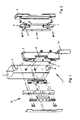
- Fig. 1 shows a post 1 for fire-resistant glazing to prevent the passage of fire and / or smoke in case of fire from one room to another room.
- the respective fire-resistant glazing in its entirety is kept, for example, in a hallway of a building or directly attached to side walls and the ceiling and the floor of a building room.
- the post 1 serves to install a frameless swing door made of glass in the fire-resistant glazing.
- the glass surface or the glass surfaces of such a fire-resistant glazing, preferably including the hinged door, are each formed by a fire protection pane or several fire protection windows.
- the fire protection panels each consist of a composite of at least two parallel glass panes, between which at least one fire protection layer is arranged, as below in connection with the embodiment of a fire-resistant glazing after Fig. 3 explained in more detail.
- the post 1 consists of two mutually parallel and spaced from each other vertically to the ground or floor extending profiles 2 and 3, between which a fire protection of a fire-resistant glazing can be used.
- the profiles 2 and 3 are each formed as metallic hollow profiles with a substantially rectangular cross-section.
- the profile 2 of the post 1 has over the profile 3 of the post 1, to which the hinges of a hinged door are fastened, a larger cross-section.
- the width of the profile 2 of the post 1 running parallel to the fire-resistant glazing is greater than the width of the profile 3 of the post 1 running parallel to the fire-resistant glazing. Due to the greater width of the profile 2 of the post 1, this forms a door stop surface for the pivoting door to be used.
- the two profiles 2 and 3 of the post 1 are connected to each other exclusively via a connecting element 4 in the area of the hinges, that is to say in the areas in which the hinges for the hinged door are fastened or fastened to the profile 2 of the post 1 ,
- the connecting element 4 is formed substantially as a steel angle 5, which is fastened by screwing with the profile 3, to which the hinges of the hinged door can be fastened.
- the steel angle 5 of the attached to the profile 3 of the post 1 connecting element 4 is then fastened by screwing to the other profile 2 of the post 2.
- two connecting angles 6 and 7 are provided on the steel angle 5 of the connecting element 4.
- the steel angle 5 of the connecting element 4 has means 8, 8 'for fastening the door hinges to the connecting element 4.
- the two profiles 2 and 3 of the post 1 are thermally separated from each other.
- the thermal separation is further increased by using a strip 9, which is insertable between the two profiles 2 and 3 of the post 1, of an insulating material.
- the strip 9 extends over the entire length of the profiles 2 and 3 of the post 1 and is interrupted only in the region of the fastening of the door hinges of the hinged door.
- Fig. 3 shows a fire-resistant glazing to prevent the passage of fire and / or smoke in case of fire from one room to another room, which in particular at least two horizontally and / or vertically aligned fire shields 10, 11, of which at least one forms a hinged door 11, which on a post 1 according to Fig. 1 and Fig. 2 is arranged pivotally by means of door hinges 12.
- FIG. 3 illustrated fire protection glazing in the form of a fire wall is suitable and intended to prevent the passage of fire and smoke in case of fire from one room to another room.
- Each is a large-scale glazing, which is composed of several fire protection panels 10, 11, which are arranged in a vertical plane aligned horizontally or vertically next to each other or one above the other.
- the fire panels 10, 11 may have different dimensions and be combined according to the architectural requirements.
- comparatively long fire protection windows can be arranged to extend in the vertical direction or in the horizontal direction.
- square fire panels can be arranged one above the other in the vertical direction and, in order to gain height, be combined with a rectangular fire protection panel in the vertical direction.
- other combinations of rectangular fire protection panels can be used to achieve a variability of the possible arrangements and thereby granted constructive freedom.
- the fire protection panel 10 consists of two parallel spaced-apart discs 13 and 14 of single-pane safety glass (toughened glass). Between the glass sheets 13 and 14, a substantially U-shaped spacer 15 made of fire-resistant and fire-resistant plastic is arranged randum running. The spacer 15 is set back slightly inwards in relation to the edges of the two glass panes 13 and 14. The circumferential groove formed thereby is filled by a PU edge seal 16, so that the two tempered glass panes 13 and 14 are fixed to each other to form a closed interior 17 in the manner of a glazing. To achieve the desired fire protection properties of this interior 17 is filled with a gel-like fire retardant. In contrast to other fire-resistant glass foams the gel-like fire retardant in case of fire and can not leave the described interior 17 of the fire protection pane.
- a gel-like fire retardant In contrast to other fire-resistant glass foams the gel-like fire retardant in case of fire and can not leave the described interior 17 of the fire protection pane.
Landscapes
- Engineering & Computer Science (AREA)
- Civil Engineering (AREA)
- Structural Engineering (AREA)
- Special Wing (AREA)
Abstract
Description
- Die vorliegende Erfindung betrifft einen Pfosten für eine Schwenktür, insbesondere für eine vorzugsweise rahmenlose Schwenktür aus Glas, vorzugsweise für eine Brandschutztür zur Vermeidung des Durchtritts von Feuer und/oder Rauch im Brandfall von einem Raum in einen anderen Raum.
- Ferner betrifft die vorliegende Erfindung eine Brandschutzverglasung zur Vermeidung des Durchtritts von Feuer und/oder Rauch im Brandfall aus einem Raum in einen anderen Raum, welche insbesondere wenigstens zwei horizontal und/oder vertikal fluchtend zueinander angeordnete Brandschutzscheiben aufweist, wobei wenigstens eine der Brandschutzscheiben eine Schwenktür ausbildet, welche an einem erfindungsgemäßen Pfosten mittels Türbändern schwenkbar anordbar bzw. angeordnet ist.
- Brandschutzverglasungen sind lichtdurchlässige Bauteile, die dazu bestimmt sind, entsprechend ihrer Feuerwiderstandsdauer nicht nur die Ausbreitung von Feuer und/oder Rauch, sondern bei Bedarf oder auf Wunsch zusätzlich auch einen unzulässigen Übergang von Wärme zu verhindern. Hierzu werden Brandschutzscheiben verwendet, die mehrlagig aus Glasscheiben mit mindestens einer dazwischen angeordneten Brandschutzschicht aus z.B. einem Intumeszenzmaterial, aufgebaut sind. Im Brandfall wird diese Brandschutzschicht aktiviert. Die Brandschutzschicht absorbiert die Wärmestrahlung und bildet eine hochwirksame Dämmschicht.
- Als Brandschutzschicht zwischen den Glasscheiben finden feste, im Brandfall aufschäumende oder anderweitig volumenvergrößernde Materialien Verwendung. Im Brandfall tritt das Brandschutzmaterial dabei aus den Stoßflächen der Brandschutzscheibe aus und verschließt eine jeweils zur angrenzenden Brandschutzscheibe, Wand oder Decke und/oder - soweit verwendet bzw. vorgesehen - Rahmensystemen bzw. -konstruktionen belassene Fuge, so dass Flammen, Rauch und/oder Wärme nicht mehr durchtreten können.
- Auch finden als Brandschutzschicht zwischen den Glasscheiben einer Brandschutzscheibe gelartige, wasserhaltige, insbesondere Alkalimetallsiliaktmasse enthaltende Materialien Verwendung, die im Brandfall nicht aufschäumen. Eine derartige Brandschutzscheibe ist aus wenigstens zwei auf Abstand gehaltenen, parallelen Glasscheiben aufgebaut, deren geschlossener Innenraum mit einem insbesondere gelartigen Brandschutzmittel gefüllt ist.
- Solche aus mehreren Glasflächen mit Brandschutzscheiben zusammengesetzte Brandschutzverglasungen weisen mitunter ein- oder zweiflügelige Schwenktüren, insbesondere aus Glas, auf. Für Brandschutzzwecke ist die Glasfläche bzw. sind die Glasflächen einer solchen Schwenktür durch eine Brandschutzscheibe bzw. mehrere Brandschutzscheiben ausgebildet.
- Da Brandschutzscheiben, insbesondere im Bereich ihrer Stirnflächen ausgesprochen empfindlich gegen mechanische Beanspruchungen sind, werden insbesondere bei Glasschwenktüren mit Brandschutzscheiben an Rahmen-, Trag- und/oder Stützkonstruktionen für Brandschutzverglasungen höhere Anforderungen gestellt als bei herkömmlichen Glasschwenktüren, auch weil Glasschwenktüren mit Brandschutzscheiben ein wesentlich höheres Gewicht aufweisen als herkömmliche Glasschwenktüren. Zu diesem Zweck ist es bekannt, bei Glasschwenktüren mit Brandschutzscheiben eine Rahmen-, Trag- und/oder Stützkonstruktion aus Metallprofilen zu verwenden. Dabei sind sämtliche Funktionsteile der Glasschwenktüren, beispielsweise Türbänder bzw. Scharniere sowie Schlossteile an der Rahmen-, Trag- und/oder Stützkonstruktion befestigt. Die Brandschutzscheiben der Brandschutzverglasung selbst können dabei ohne Rahmenprofile, mit vertikal zum Untergrund verlaufenden Rahmenprofilen, und/oder mit horizontal zum Untergrund verlaufenden Rahmenprofilen versehen sein.
- Bei Verwendung von bisher bekannten Rahmen-, Trag- und/oder Stützkonstruktion aus Metallprofilen ist es bei Brandschutzverglasungen im Brandfall nachteilig, dass die Stabilität der Rahmen-, Trag- und/oder Stützkonstruktion aufgrund einer unterschiedlichen Wärme- bzw. Hitzeentwicklung auf der brandzugewandten Seite und auf der brandabgewandten Seite und der damit verbundenen unterschiedlichen Verformung der Rahmen-, Trag- und/oder Stützkonstruktion auf der brandzugewandten Seite und auf der brandabgewandten Seite erheblich reduziert wird. Die thermisch leitend miteinander in Verbindung stehenden Metallprofile der Rahmen-, Trag- und/oder Stützkonstruktion verformen sich dabei aufgrund der unterschiedlichen Wärme- bzw. Hitzeentwicklung auf der brandzugewandten Seite und auf der brandabgewandten Seite ebenfalls unterschiedlich, so dass im Bereich der Rahmen-, Trag- und/oder Stützkonstruktion einer Brandschutzverglasung Spalte entstehen können, durch die Feuer und/oder Rauch im Brandfall von einem Raum in einen anderen Raum gelangen kann. Die Verformungen der Rahmen-, Trag- und/oder Stützkonstruktion einer Brandschutzverglasung können dabei im Brandfall insbesondere bei Verwendung von an den Profilen der Rahmen-, Trag- und/oder Stützkonstruktion schwenkbar angeschlagenen Türen aufgrund des im Vergleich mit herkömmlichen Glastüren gegebenen höheren Gewichtes von Brandschutzscheiben derart groß werden, dass die Rahmen-, Trag- und/oder Stützkonstruktion die Brandschutzscheiben, insbesondere die als Schwenktür ausgebildeten Brandschutzscheiben nicht mehr sicher halten kann.
- In Anbetracht dieses Standes der Technik liegt der Erfindung die Aufgabe zugrunde, einen Pfosten als Tragkonstruktion für eine Schwenktür bereitzustellen, der für hohe startische und dynamische Belastungen geeignet ist, der auch bei derartigen Belastungen scharnierbandseitig eine schmale Querschnittsgestaltung und in der Ausbildung für Brandschutzzwecke in einer Brandschutzverglasung eine weitestgehend thermische Trennung ermöglicht.
- Zur technischen Lösung dieser Aufgabe wird mit der vorliegenden Erfindung ein Pfosten für eine Schwenktür, insbesondere für eine rahmenlose Schwenktür aus Glas, vorzugsweise für eine Brandschutzverglasung vorgeschlagen, der gekennzeichnet ist durch zwei parallel zueinander und beabstandet voneinander vertikal zum Untergrund verlaufend anordbaren Profilen, wobei an dem einen Profil Türbänder der Schwenktür befestigbar sind und die beiden Profile ausschließlich in dem Bereich der Türbänder jeweils über ein Verbindungselement miteinander verbunden sind.
- Der Erfindung liegt die Erkenntnis zugrunde, dass durch diese Ausgestaltung des Pfostens für eine Schwenktür, insbesondere für eine Brandschutzverglasung, eine unterschiedliche Wärme- bzw. Hitzeentwicklung auf der brandzugewandten Seite und auf der brandabgewandten Seite nicht zu einer Spalte erzeugenden unterschiedlichen Verformung des Pfostens führt, da die Profile des Pfosten - abgesehen von dem Bereich der Türbänder - thermisch voneinander getrennt sind und die durch das Gewicht der Schwenktür im Bereich der Türbänder einwirkenden Kräfte von dem einen auf das andere Profil übertragen werden. Erfindungsgemäß ist damit keine durchgängige schubfeste Verbindung zwischen den Profilen gegeben, so dass Verformungen im Brandfall geringer sind. Durch die thermische Trennung der Profile des erfindungsgemäßen Pfostens kann dieser auch im Brandfall eine Brandschutzscheiben aufweisende Schwenktür sicherer und dichter halten, verglichen mit herkömmlichen Rahmen-, Trag- und/oder Stützkonstruktion zumindest für eine längere Zeit.
- Vorteilhafterweise sind die beiden Profile des Pfostens durch Befestigung der Türbänder an einem der Profile miteinander verbindbar, das heißt, dass die Befestigung der Türbänder gleichzeitig zur Verbindung der beiden Profile verwendbar ist.
- Eine vorteilhafte Ausgestaltung der Erfindung sieht vor, dass die beiden Profile ansonsten - also abgesehen von der Verbindung derselben über das Verbindungselement - thermisch voneinander getrennt sind, vorzugsweise durch Verwendung eines Streifens aus einem isolierenden Material, welcher zwischen den beiden Profilen einsetzbar ist. Die thermische Trennung zwischen den Profilen des Pfostens erlaubt darüber hinaus zwischen den Profilen eine Kühlung zu erzielen.
- Eine weitere vorteilhafte Ausgestaltung der Erfindung ist dadurch gekennzeichnet, dass das Verbindungselement im wesentlichen als Stahlwinkel ausgebildet ist, der mit dem Profil, an welchem die Türbänder der Schwenktür befestigbar sind, befestigt oder befestigbar ist, vorzugsweise durch Verschraubung, und der an dem anderen Profil durch Verschraubung befestigt oder befestigbar ist.
- Eine weitere vorteilhafte Ausgestaltung der Erfindung sieht vor, dass das Verbindungselement Mittel zur Befestigung eines Türbandes an dem Profil an welchem die Türbänder der Schwenktür befestigbar sind aufweist oder aufnimmt. So können die Türbänder der Schwenktür vorteilhafterweise montiert werden, wenn die Profile des Pfostens bereits montiert sind, wodurch sich Feineinstellungen hinsichtlich der Passung bzw. des Spiels der Schwenktür leichter einstellen lassen.
- Gemäß einer weiteren vorteilhaften Ausgestaltung der Erfindung sind die Profile mit einem im wesentlichen rechteckigen Querschnitt ausgestaltet, vorzugsweise als Hohlprofile.
- Vorzugsweise ist der Querschnitt des Profils, an welchem die Türbänder der Schwenktür befestigbar sind, kleiner als der Querschnitt des anderen Profils.
- Hierdurch ist gewährleistet, dass die schamierbandseitig von dem kleineren Profil aufgenommenen Kräfte, die im Brandfall außerordentlich hoch sein können, über die Verbindungselemente übertragen werden auf das vergleichsweise große Profil, das zur Aufnahme dieser Belastungen entsprechend dimensioniert ist, während für alle Einsatzbereiche das kleinere scharnierbandseitige Profil in konstanten Abmessungen verwendet werden kann.
- Eine weitere vorteilhafte Ausgestaltung der Erfindung sieht vor, dass die Breite des Profils, an welchem die Türbänder der Schwenktür befestigbar sind, kleiner ist als die Breite des anderen Profils. Vorteilhafterweise kann so von dem breiteren Profil des Pfostens ein Türanschlag für die Schwenktür ausgebildet werden.
- Vorteilhafterweise ist die Tiefe des anderen Profils in Abhängigkeit von den statischen Anforderungen der Brandschutzverglasung wählbar. Die Profile des erfindungsgemäßen Pfostens sind so als Systemkomponenten in Abhängigkeit von den jeweiligen statischen Anforderungen der Brandschutzverglasung zusammensetzbar. Das hinsichtlich des Querschnitts kleinere und zur Befestigung der Türbänder der Schwenktür vorgesehene Profil kann dabei wie vorbeschrieben stets gleich ausgebildet werden, während das andere im Querschnitt größere Profil hinsichtlich seiner Größe in Abhängigkeit von den jeweiligen statischen und dynamischen Anforderungen der Brandschutzverglasung ausgewählt wird. Je höher diese Anforderungen der Brandschutzverglasung sind, desto größer wird die Tiefe des anderen Profils gewählt.
- Gemäß einer weiteren Ausgestaltung der Erfindung sind die Profile aus Metall, vorzugsweise Aluminium, Stahl oder Edelstahl.
- Vorteilhafterweise sind an dem erfindungsgemäßen Pfosten wenigstens zwei Türbänder befestigbar.
- Gegenstand der vorliegenden Erfindung ist ferner eine Brandschutzverglasung zur Vermeidung des Durchtritts von Feuer und/oder Rauch im Brandfall aus einem Raum in einen anderen Raum, welche insbesondere wenigstens zwei horizontal und/oder vertikal fluchtend zueinander angeordnete Brandschutzscheiben aufweist und dadurch gekennzeichnet ist, dass wenigstens eine der Brandschutzscheiben eine Schwenktür ausbildet, welche an einem erfindungsgemäßen mittels Türbändern schwenkbar anordbar bzw. angeordnet ist.
- Weitere Einzelheiten, Merkmale und Vorteile des Gegenstandes der Erfindung werden nachfolgend anhand des in den Figuren der Zeichnung dargestellten Ausführungsbeispiels näher erläutert. Dabei zeigen:
- Fig. 1
- in einer schematisch perspektivischen Ansicht eine Explosionsdarstellung eines Ausführungsbeispiels eines erfindungsgemäßen Pfostens einer Brandschutzverglasung, vorliegend im Bereich der Befestigung eines Türbandes einer Schwenktür;
- Fig. 2
- in einer schematisch perspektivischen Ansicht eine Explosionsdarstellung eines Ausführungsbeispiels eines zur Befestigung der Türbänder einer Schwenktür ausgebildeten Profils des erfindungsgemäßen Pfostens einer Brandschutzverglasung nach
Fig. 1 ; und - Fig. 3
- in einer schematischen Ansicht von oben ein Ausführungsbeispiel einer erfindungsgemäßen Brandschutzverglasung mit einem erfindungsgemäßen Pfosten für eine Schwenktür.
-
Fig. 1 zeigt einen Pfosten 1 für Brandschutzverglasung zur Vermeidung des Durchtritts von Feuer und/oder Rauch im Brandfall von einem Raum in einen anderen Raum. Die jeweilige Brandschutzverglasung in ihrer Gesamtheit ist beispielsweise in einem Flur eines Gebäudes gehalten oder unmittelbar an seitlichen Wänden sowie der Decke und dem Boden eines Gebäuderaumes befestigt. Der Pfosten 1 dient dabei zum Einbau einer rahmenlosen Schwenktür aus Glas in die Brandschutzverglasung. Die Glasfläche bzw. die Glasflächen einer solchen Brandschutzverglasung, vorzugsweise einschließlich der Schwenktür, sind dabei jeweils durch eine Brandschutzscheibe bzw. mehrere Brandschutzscheiben ausgebildet. Die Brandschutzscheiben bestehen jeweils aus einem Verbund von wenigstens zwei parallelen Glasscheiben, zwischen denen wenigstens eine Brandschutzschicht angeordnet ist, wie nachfolgend noch im Zusammenhang mit dem Ausführungsbeispiel einer Brandschutzverglasung nachFig. 3 näher erläutert. - Der Pfosten 1 besteht aus zwei parallel zueinander und beabstandet voneinander vertikal zum Untergrund bzw. Boden verlaufend angeordneten Profilen 2 und 3, zwischen denen eine Brandschutzscheibe einer Brandschutzverglasung einsetzbar ist. Die Profile 2 und 3 sind jeweils als metallische Hohlprofile mit einem im wesentlichen rechteckigen Querschnitt ausgebildet. Das Profil 2 des Pfostens 1 weist gegenüber dem Profil 3 des Pfostens 1, an welchem die Türbänder einer Schwenktür befestigbar sind, einen größeren Querschnitt auf. Ferner ist die parallel zur Brandschutzverglasung verlaufende Breite des Profils 2 des Pfostens 1 größer als die parallel zur Brandschutzverglasung verlaufende Breite des Profils 3 des Pfostens 1. Durch die größere Breite des Profils 2 des Pfostens 1 bildet dieser eine Türanschlagsfläche für die einzusetzende Schwenktür aus. Die beiden Profile 2 und 3 des Pfostens 1 sind ausschließlich in dem Bereich der Türbänder, das heißt in den Bereichen, in denen die Türbänder für die Schwenktür an dem Profil 2 des Pfostens 1 befestigt bzw. befestigbar sind, jeweils über ein Verbindungselement 4 miteinander verbunden. Das Verbindungselement 4 ist dabei im wesentlichen als Stahlwinkel 5 ausgebildet, der mit dem Profil 3, an welchem die Türbänder der Schwenktür befestigbar sind, durch Verschraubung befestigt wird. Der Stahlwinkel 5 des an dem Profil 3 des Pfostens 1 befestigten Verbindungselements 4 wird dann durch Verschraubung an dem anderen Profil 2 des Pfostens 2 befestigt. Dazu sind an dem Stahlwinkel 5 des Verbindungselements 4 zwei Verbindungswinkel 6 und 7 vorgesehen. Ferner weist der Stahlwinkel 5 des Verbindungselements 4 Mittel 8, 8' zur Befestigung der Türbänder an dem Verbindungselement 4 auf.
- Abgesehen von der Verbindung der beiden Profile 2 und 3 des Pfostens 1 über das Verbindungselement 4, sind die beiden Profile 2 und 3 des Pfostens 1 thermisch voneinander getrennt. Die thermische Trennung wird durch Verwendung eines Streifens 9, welcher zwischen den beiden Profilen 2 und 3 des Pfostens 1 einsetzbar ist, aus einem isolierenden Material, weiter gesteigert. Der Streifen 9 erstreckt sich dabei über die gesamte Länge der Profile 2 und 3 des Pfostens 1 und ist nur im Bereich der Befestigung der Türbänder der Schwenktür unterbrochen.
-
Fig. 3 zeigt eine Brandschutzverglasung zur Vermeidung des Durchtritts von Feuer und/oder Rauch im Brandfall aus einem Raum in einen anderen Raum, welche insbesondere wenigstens zwei horizontal und/oder vertikal fluchtend zueinander angeordnete Brandschutzscheiben 10, 11 aufweist, von denen wenigstens eine eine Schwenktür 11 ausbildet, welche an einem Pfosten 1 gemäßFig. 1 und Fig. 2 mittels Türbändern 12 schwenkbar angeordnet ist. - Die in
Fig. 3 dargestellte Brandschutzverglasung in Form einer Feuerschutztrennwand ist geeignet und vorgesehen, den Durchtritt von Feuer und Rauch im Brandfall aus einem Raum in einen anderen Raum zu verhindern. Es handelt sich jeweils um eine großflächige Verglasung, die aus mehreren Brandschutzscheiben 10, 11 aufgebaut ist, welche in einer senkrechten Ebene fluchtend horizontal bzw. vertikal nebeneinander bzw. übereinander angeordnet sind. Die Brandschutzscheiben 10, 11 können unterschiedliche Abmessungen aufweisen und entsprechend den architektonischen Erfordernissen, miteinander kombiniert werden. So können vergleichsweise lange Brandschutzscheiben sich in vertikaler Richtung oder horizontaler Richtung erstreckend angeordnet werden. Ferner können quadratische Brandschutzscheiben in vertikaler Richtung übereinander angeordnet, und dazu - um Höhe zu gewinnen - mit einer rechteckigen Brandschutzscheibe in senkrechter Richtung kombiniert werden. Darüber hinaus sind weitere Kombinationen von Rechteck-Brandschutzscheiben verwendbar, um eine Variabilität der möglichen Anordnungen und eine dadurch gewährte konstruktive Freiheit zu erzielen. - Die Brandschutzscheibe 10 besteht aus zwei parallel mit Abstand zueinander angeordneten Scheiben 13 und 14 aus Einscheibensicherheitsglas (ESG-Scheibe). Zwischen den Glasscheiben 13 und 14 ist randumlaufend ein im wesentlichen U-förmiger Abstandhalter 15 aus brandschutzmittelbeständigem und feuerresistentem Kunststoff angeordnet. Der Abstandhalter 15 ist etwas nach innen gegenüber den Rändern der beiden Glasscheiben 13 und 14 zurückversetzt. Die dadurch gebildete umlaufende Nut ist durch einen PU-Randverbund 16 ausgefüllt, so dass die beiden ESG-Scheiben 13 und 14 aneinander unter Bildung eines geschlossenen Innenraums 17 nach Art einer Isolierverglasung fixiert sind. Zur Erzielung der gewünschten Brandschutzeigenschaften ist dieser Innenraum 17 mit einem gelartigen Brandschutzmittel gefüllt. Im Gegensatz zu anderen Brandschutzgläsern schäumt das gelartige Brandschutzmittel im Brandfall nicht auf und kann auch den beschriebenen Innenraum 17 der Brandschutzscheibe nicht verlassen.
- Die in den Figuren der Zeichnung dargestellten und im Zusammenhang mit diesen erläuterten Ausführungsbeispiele der Erfindung dienen lediglich der Erläuterung der Erfindung und sind für diese nicht beschränkend.
-
- 1
- Pfosten
- 2
- Profil
- 3
- Profil
- 4
- Verbindungselement
- 5
- Stahlwinkel
- 6
- Verbindungswinkel
- 7
- Verbindungswinkel
- 8
- Mittel zur Befestigung von Türband
- 9
- Streifen aus isolierenden Material
- 10
- Brandschutzscheibe
- 11
- Brandschutzscheibe/Schwenktür
- 12
- Türband
- 13
- Glasscheibe (Einscheibensicherheitsglas (ESG-Scheibe))
- 14
- Glasscheibe (Einscheibensicherheitsglas (ESG-Scheibe))
- 15
- Abstandshalter
- 16
- Randverbund
- 17
- Brandschutzschicht/Brandschutzmittel
- B
- Breite
- B'
- Breite
- T
- Tiefe
Claims (11)
- Pfosten (1) für eine Schwenktür (11), insbesondere für eine rahmenlose Schwenktür aus Glas, gekennzeichnet durch zwei parallel zueinander und beabstandet voneinander vertikal zum Untergrund verlaufend anordbaren Profilen (2, 3) wobei an dem einen Profil (3) der beiden Profile (2, 3) Türbänder (12) der Schwenktür (11) befestigbar sind und die beiden Profile (2, 3) ausschließlich in dem Bereich der Türbänder (12) jeweils über ein Verbindungselement miteinander verbunden sind.
- Pfosten (1) nach Anspruch 1, dadurch gekennzeichnet, dass die beiden Profile (2, 3) ansonsten thermisch voneinander getrennt sind.
- Pfosten (1) nach Anspruch 1 oder 2, dadurch gekennzeichnet, dass zwischen den beiden Profilen (2, 3) ein Streifen (9) aus einem Isoliermaterial eingesetzt ist.
- Pfosten (1) nach einem der Ansprüche 1 bis 3, dadurch gekennzeichnet, dass die Profile (2, 3) als Hohlprofile mit im Wesentlichen rechteckigen Querschnitt ausgestaltet sind.
- Pfosten (1) nach einem der Ansprüche 1 bis 4, dadurch gekennzeichnet, dass der Querschnitt des einen Profils (3), an welchem die Türbänder (12) der Schwenktür (11) befestigbar sind, kleiner ist als der Querschnitt des anderen Profils (2).
- Pfosten (1) nach einem der Ansprüche 1 bis 5, dadurch gekennzeichnet, dass die Breite (B) des einen Profils (3) an welchem die Türbänder (12) der Schwenktür (11) befestigbar sind, kleiner ist als die Breite (B') des anderen Profils (2) und derart einen Türanschlag bildet.
- Pfosten (1) nach einem der Ansprüche 1 bis 6, dadurch gekennzeichnet, dass die Tiefe (T) und/oder die Breite (B') des anderen Profils (2) in Abhängigkeit von den statischen Anforderungen derart ausgestaltet ist, dass mit größeren statischen Anforderungen die Tiefe (T) und/oder Breite (B') des anderen Profils (2) im Vergleich zu den Abmessungen des einen Profils (2) progressiv steigen.
- Pfosten (1) nach einem der Ansprüche 1 bis 7, dadurch gekennzeichnet, dass die Profile (2, 3) aus Metall, vorzugsweise aus Stahl bestehen.
- Pfosten (1) nach einem der Ansprüche 1 bis 8, dadurch gekennzeichnet, dass das Verbindungselement (4) als Stahlwinkel (5) ausgebildet ist, der mit beiden Profilen (2, 3) im Bereich eines Türbandes (12) durch Verschraubung befestigt oder befestigbar ist.
- Pfosten (1) nach einem der Ansprüche 1 bis 9, dadurch gekennzeichnet, dass das Verbindungselement (4) Mittel (8, 8') zur Befestigung eines Türbandes (12) an dem einen Profil (3), an welchem die Türbänder in (12) der Schwenktür (11) befestigbar sind, aufweist oder aufnimmt.
- Brandschutzverglasung zur Vermeidung des Durchtritts von Feuer und/oder Rauch im Brandfall aus einem Raum in einen anderen Raum, welche wenigstens zwei fluchtend zueinander angeordnete Brandschutzschreiben (10, 11) aufweist, dadurch gekennzeichnet, dass wenigstens eine der Bandschutzscheiben (11) als Schwenktür (11) ausgebildet ist, welche an einem Pfosten (1) nach einem der Ansprüche 1 bis 10 mittels Türbändern (12) schwenkbar anordbar bzw. angeordnet ist.
Priority Applications (1)
| Application Number | Priority Date | Filing Date | Title |
|---|---|---|---|
| PL14184100T PL2845982T3 (pl) | 2013-09-09 | 2014-09-09 | Słupek do drzwi wahadłowych i szkło przeciwpożarowe z takim słupkiem |
Applications Claiming Priority (1)
| Application Number | Priority Date | Filing Date | Title |
|---|---|---|---|
| DE201320104081 DE202013104081U1 (de) | 2013-09-09 | 2013-09-09 | Pfosten für eine Schwenktür und Brandschutzverglasung mit einem solchen Pfosten |
Publications (3)
| Publication Number | Publication Date |
|---|---|
| EP2845982A2 true EP2845982A2 (de) | 2015-03-11 |
| EP2845982A3 EP2845982A3 (de) | 2015-06-24 |
| EP2845982B1 EP2845982B1 (de) | 2017-12-13 |
Family
ID=51494162
Family Applications (1)
| Application Number | Title | Priority Date | Filing Date |
|---|---|---|---|
| EP14184100.7A Active EP2845982B1 (de) | 2013-09-09 | 2014-09-09 | Pfosten für eine Schwenktür und Brandschutzverglasung mit einem solchen Pfosten |
Country Status (3)
| Country | Link |
|---|---|
| EP (1) | EP2845982B1 (de) |
| DE (1) | DE202013104081U1 (de) |
| PL (1) | PL2845982T3 (de) |
Family Cites Families (9)
| Publication number | Priority date | Publication date | Assignee | Title |
|---|---|---|---|---|
| FR1602678A (de) * | 1968-08-19 | 1971-01-11 | ||
| US4409769A (en) * | 1980-08-25 | 1983-10-18 | Kawneer Company, Inc. | Heat insulated entrance |
| DE3907280C2 (de) * | 1989-03-07 | 1994-03-17 | Sommer Metallbau Stahlbau Gmbh | Tür, insbesondere für in Räumen oder Etagen angeordnete Trennwände |
| DE9103671U1 (de) * | 1991-03-26 | 1991-06-27 | PROMAT GmbH, 4030 Ratingen | Glastür für Brandschutzzwecke |
| JPH11512158A (ja) * | 1995-09-05 | 1999-10-19 | ノルスク ハイドロ アー.エス. | 断熱された複合断面材 |
| DE29819678U1 (de) * | 1998-11-04 | 1999-01-14 | Holzbau Schmid GmbH & Co. KG, 73099 Adelberg | Brandschutzverglasung |
| AT504806B1 (de) * | 2007-01-15 | 2013-12-15 | Walter Ing Degelsegger | Zarge für feuerschutztüren, welche aus mehreren parallel verlaufenden teilprofilen gebildet wird |
| DE202011106509U1 (de) * | 2011-10-10 | 2011-12-01 | Holzbau Schmid Gmbh & Co. Kg | Profillose Brandschutzverglasung mit Tür |
| DE202012101540U1 (de) * | 2012-04-25 | 2012-05-23 | Holzbau Schmid Gmbh & Co. Kg | Zargenfreie Brandschutz-Ganzglastür |
-
2013
- 2013-09-09 DE DE201320104081 patent/DE202013104081U1/de not_active Expired - Lifetime
-
2014
- 2014-09-09 EP EP14184100.7A patent/EP2845982B1/de active Active
- 2014-09-09 PL PL14184100T patent/PL2845982T3/pl unknown
Non-Patent Citations (1)
| Title |
|---|
| None |
Also Published As
| Publication number | Publication date |
|---|---|
| EP2845982B1 (de) | 2017-12-13 |
| DE202013104081U1 (de) | 2014-12-10 |
| EP2845982A3 (de) | 2015-06-24 |
| PL2845982T3 (pl) | 2018-06-29 |
Similar Documents
| Publication | Publication Date | Title |
|---|---|---|
| EP2581515B1 (de) | Profillose Brandschutzverglasung mit Tür | |
| AT4250U1 (de) | Brandschutztür mit einem diese umfassenden türstock | |
| DE202009002800U1 (de) | Brandschutzverglasung | |
| DE19635409B4 (de) | Glastür für Brandschutzzwecke sowie Verfahren zum Herstellen einer Glastür für Brandschutzzwecke | |
| EP2327855B1 (de) | Isolierglaseinheit und Tragkonstruktion mit mindestens einer derartigen Isolierglaseinheit | |
| EP1566514A2 (de) | Brandschutzverglasung | |
| EP2657012B1 (de) | Zargenfreie Brandschutz-Ganzglastür | |
| EP3216966A1 (de) | Einrichtung zum schliessen einer öffnung für brandschutzzwecke | |
| EP2405093A2 (de) | Modulare Brandschutzverglasung | |
| EP2845982B1 (de) | Pfosten für eine Schwenktür und Brandschutzverglasung mit einem solchen Pfosten | |
| EP2312104A1 (de) | Feuerschutztür | |
| EP2754830A2 (de) | Profillose Brandschutzverglasung | |
| EP2581534A1 (de) | Klemmhalter | |
| EP3530860B1 (de) | Isolierglaselement für eine glasfassade und glasfassade | |
| DE10319278A1 (de) | Fassadenelement zum Verkleiden einer Gebäudewand | |
| EP3168406B1 (de) | Isolierglaselement und glasfassade | |
| DE202013100151U1 (de) | Schallschutzeinrichtung | |
| DE102007053659A1 (de) | Gebäudefassade in Brandschutzausführung | |
| DE102010032947A1 (de) | Aufsatzkonstruktion für Holz Pfosten/Riegelelemente mit verbesserter Wärmeisoliereigenschaft | |
| EP1484468A2 (de) | Isolierglasrahmen | |
| DE102017104901A1 (de) | Isolierfenster | |
| DE20312428U1 (de) | Tür, insbesondere Haustür für Passivhäuser | |
| DE202013102946U1 (de) | Türsystem aus einem Türflügel und wenigstens einem Festfeld | |
| DE102014117490A1 (de) | Optimierte Falzbefestigung in einem Tür- oder Fensterrahmen | |
| DE202006007027U1 (de) | Verbundfensterkonstruktion und damit hergestellte Fenster und Türen |
Legal Events
| Date | Code | Title | Description |
|---|---|---|---|
| 17P | Request for examination filed |
Effective date: 20140909 |
|
| AK | Designated contracting states |
Kind code of ref document: A2 Designated state(s): AL AT BE BG CH CY CZ DE DK EE ES FI FR GB GR HR HU IE IS IT LI LT LU LV MC MK MT NL NO PL PT RO RS SE SI SK SM TR |
|
| AX | Request for extension of the european patent |
Extension state: BA ME |
|
| PUAI | Public reference made under article 153(3) epc to a published international application that has entered the european phase |
Free format text: ORIGINAL CODE: 0009012 |
|
| PUAL | Search report despatched |
Free format text: ORIGINAL CODE: 0009013 |
|
| AK | Designated contracting states |
Kind code of ref document: A3 Designated state(s): AL AT BE BG CH CY CZ DE DK EE ES FI FR GB GR HR HU IE IS IT LI LT LU LV MC MK MT NL NO PL PT RO RS SE SI SK SM TR |
|
| AX | Request for extension of the european patent |
Extension state: BA ME |
|
| RIC1 | Information provided on ipc code assigned before grant |
Ipc: E06B 5/16 20060101AFI20150521BHEP Ipc: B32B 17/10 20060101ALI20150521BHEP Ipc: E06B 3/02 20060101ALI20150521BHEP |
|
| R17P | Request for examination filed (corrected) |
Effective date: 20160104 |
|
| RBV | Designated contracting states (corrected) |
Designated state(s): AL AT BE BG CH CY CZ DE DK EE ES FI FR GB GR HR HU IE IS IT LI LT LU LV MC MK MT NL NO PL PT RO RS SE SI SK SM TR |
|
| 17Q | First examination report despatched |
Effective date: 20161207 |
|
| GRAP | Despatch of communication of intention to grant a patent |
Free format text: ORIGINAL CODE: EPIDOSNIGR1 |
|
| INTG | Intention to grant announced |
Effective date: 20170724 |
|
| GRAS | Grant fee paid |
Free format text: ORIGINAL CODE: EPIDOSNIGR3 |
|
| GRAA | (expected) grant |
Free format text: ORIGINAL CODE: 0009210 |
|
| REG | Reference to a national code |
Ref country code: GB Ref legal event code: FG4D Free format text: NOT ENGLISH |
|
| REG | Reference to a national code |
Ref country code: AT Ref legal event code: REF Ref document number: 954547 Country of ref document: AT Kind code of ref document: T Effective date: 20171215 Ref country code: CH Ref legal event code: EP |
|
| REG | Reference to a national code |
Ref country code: IE Ref legal event code: FG4D Free format text: LANGUAGE OF EP DOCUMENT: GERMAN |
|
| REG | Reference to a national code |
Ref country code: DE Ref legal event code: R096 Ref document number: 502014006541 Country of ref document: DE |
|
| REG | Reference to a national code |
Ref country code: NL Ref legal event code: FP |
|
| PG25 | Lapsed in a contracting state [announced via postgrant information from national office to epo] |
Ref country code: SE Free format text: LAPSE BECAUSE OF FAILURE TO SUBMIT A TRANSLATION OF THE DESCRIPTION OR TO PAY THE FEE WITHIN THE PRESCRIBED TIME-LIMIT Effective date: 20171213 Ref country code: FI Free format text: LAPSE BECAUSE OF FAILURE TO SUBMIT A TRANSLATION OF THE DESCRIPTION OR TO PAY THE FEE WITHIN THE PRESCRIBED TIME-LIMIT Effective date: 20171213 Ref country code: NO Free format text: LAPSE BECAUSE OF FAILURE TO SUBMIT A TRANSLATION OF THE DESCRIPTION OR TO PAY THE FEE WITHIN THE PRESCRIBED TIME-LIMIT Effective date: 20180313 |
|
| PG25 | Lapsed in a contracting state [announced via postgrant information from national office to epo] |
Ref country code: BG Free format text: LAPSE BECAUSE OF FAILURE TO SUBMIT A TRANSLATION OF THE DESCRIPTION OR TO PAY THE FEE WITHIN THE PRESCRIBED TIME-LIMIT Effective date: 20180313 Ref country code: RS Free format text: LAPSE BECAUSE OF FAILURE TO SUBMIT A TRANSLATION OF THE DESCRIPTION OR TO PAY THE FEE WITHIN THE PRESCRIBED TIME-LIMIT Effective date: 20171213 Ref country code: LV Free format text: LAPSE BECAUSE OF FAILURE TO SUBMIT A TRANSLATION OF THE DESCRIPTION OR TO PAY THE FEE WITHIN THE PRESCRIBED TIME-LIMIT Effective date: 20171213 Ref country code: GR Free format text: LAPSE BECAUSE OF FAILURE TO SUBMIT A TRANSLATION OF THE DESCRIPTION OR TO PAY THE FEE WITHIN THE PRESCRIBED TIME-LIMIT Effective date: 20180314 Ref country code: HR Free format text: LAPSE BECAUSE OF FAILURE TO SUBMIT A TRANSLATION OF THE DESCRIPTION OR TO PAY THE FEE WITHIN THE PRESCRIBED TIME-LIMIT Effective date: 20171213 |
|
| PG25 | Lapsed in a contracting state [announced via postgrant information from national office to epo] |
Ref country code: SK Free format text: LAPSE BECAUSE OF FAILURE TO SUBMIT A TRANSLATION OF THE DESCRIPTION OR TO PAY THE FEE WITHIN THE PRESCRIBED TIME-LIMIT Effective date: 20171213 Ref country code: EE Free format text: LAPSE BECAUSE OF FAILURE TO SUBMIT A TRANSLATION OF THE DESCRIPTION OR TO PAY THE FEE WITHIN THE PRESCRIBED TIME-LIMIT Effective date: 20171213 Ref country code: CY Free format text: LAPSE BECAUSE OF FAILURE TO SUBMIT A TRANSLATION OF THE DESCRIPTION OR TO PAY THE FEE WITHIN THE PRESCRIBED TIME-LIMIT Effective date: 20171213 Ref country code: ES Free format text: LAPSE BECAUSE OF FAILURE TO SUBMIT A TRANSLATION OF THE DESCRIPTION OR TO PAY THE FEE WITHIN THE PRESCRIBED TIME-LIMIT Effective date: 20171213 |
|
| PG25 | Lapsed in a contracting state [announced via postgrant information from national office to epo] |
Ref country code: RO Free format text: LAPSE BECAUSE OF FAILURE TO SUBMIT A TRANSLATION OF THE DESCRIPTION OR TO PAY THE FEE WITHIN THE PRESCRIBED TIME-LIMIT Effective date: 20171213 Ref country code: IS Free format text: LAPSE BECAUSE OF FAILURE TO SUBMIT A TRANSLATION OF THE DESCRIPTION OR TO PAY THE FEE WITHIN THE PRESCRIBED TIME-LIMIT Effective date: 20180413 Ref country code: IT Free format text: LAPSE BECAUSE OF FAILURE TO SUBMIT A TRANSLATION OF THE DESCRIPTION OR TO PAY THE FEE WITHIN THE PRESCRIBED TIME-LIMIT Effective date: 20171213 Ref country code: SM Free format text: LAPSE BECAUSE OF FAILURE TO SUBMIT A TRANSLATION OF THE DESCRIPTION OR TO PAY THE FEE WITHIN THE PRESCRIBED TIME-LIMIT Effective date: 20171213 |
|
| REG | Reference to a national code |
Ref country code: DE Ref legal event code: R097 Ref document number: 502014006541 Country of ref document: DE |
|
| REG | Reference to a national code |
Ref country code: FR Ref legal event code: PLFP Year of fee payment: 5 |
|
| PG25 | Lapsed in a contracting state [announced via postgrant information from national office to epo] |
Ref country code: MT Free format text: LAPSE BECAUSE OF FAILURE TO SUBMIT A TRANSLATION OF THE DESCRIPTION OR TO PAY THE FEE WITHIN THE PRESCRIBED TIME-LIMIT Effective date: 20171213 |
|
| PLBE | No opposition filed within time limit |
Free format text: ORIGINAL CODE: 0009261 |
|
| STAA | Information on the status of an ep patent application or granted ep patent |
Free format text: STATUS: NO OPPOSITION FILED WITHIN TIME LIMIT |
|
| 26N | No opposition filed |
Effective date: 20180914 |
|
| PG25 | Lapsed in a contracting state [announced via postgrant information from national office to epo] |
Ref country code: DK Free format text: LAPSE BECAUSE OF FAILURE TO SUBMIT A TRANSLATION OF THE DESCRIPTION OR TO PAY THE FEE WITHIN THE PRESCRIBED TIME-LIMIT Effective date: 20171213 |
|
| PG25 | Lapsed in a contracting state [announced via postgrant information from national office to epo] |
Ref country code: SI Free format text: LAPSE BECAUSE OF FAILURE TO SUBMIT A TRANSLATION OF THE DESCRIPTION OR TO PAY THE FEE WITHIN THE PRESCRIBED TIME-LIMIT Effective date: 20171213 |
|
| PG25 | Lapsed in a contracting state [announced via postgrant information from national office to epo] |
Ref country code: MC Free format text: LAPSE BECAUSE OF FAILURE TO SUBMIT A TRANSLATION OF THE DESCRIPTION OR TO PAY THE FEE WITHIN THE PRESCRIBED TIME-LIMIT Effective date: 20171213 |
|
| REG | Reference to a national code |
Ref country code: LU Ref legal event code: HC Owner name: ETEX BUILDING PERFORMANCE GMBH; AT Free format text: FORMER OWNER: PROMAT GMBH Effective date: 20190521 |
|
| REG | Reference to a national code |
Ref country code: IE Ref legal event code: MM4A Ref country code: BE Ref legal event code: HC Owner name: ETEX BUILDING PERFORMANCE GMBH; DE Free format text: DETAILS ASSIGNMENT: CHANGE OF OWNER(S), CHANGEMENT DE NOM DU PROPRIETAIRE; FORMER OWNER NAME: PROMAT GMBH Effective date: 20190514 |
|
| PG25 | Lapsed in a contracting state [announced via postgrant information from national office to epo] |
Ref country code: IE Free format text: LAPSE BECAUSE OF NON-PAYMENT OF DUE FEES Effective date: 20180909 |
|
| PG25 | Lapsed in a contracting state [announced via postgrant information from national office to epo] |
Ref country code: TR Free format text: LAPSE BECAUSE OF FAILURE TO SUBMIT A TRANSLATION OF THE DESCRIPTION OR TO PAY THE FEE WITHIN THE PRESCRIBED TIME-LIMIT Effective date: 20171213 |
|
| PG25 | Lapsed in a contracting state [announced via postgrant information from national office to epo] |
Ref country code: HU Free format text: LAPSE BECAUSE OF FAILURE TO SUBMIT A TRANSLATION OF THE DESCRIPTION OR TO PAY THE FEE WITHIN THE PRESCRIBED TIME-LIMIT; INVALID AB INITIO Effective date: 20140909 Ref country code: PT Free format text: LAPSE BECAUSE OF FAILURE TO SUBMIT A TRANSLATION OF THE DESCRIPTION OR TO PAY THE FEE WITHIN THE PRESCRIBED TIME-LIMIT Effective date: 20171213 |
|
| PG25 | Lapsed in a contracting state [announced via postgrant information from national office to epo] |
Ref country code: LT Free format text: LAPSE BECAUSE OF FAILURE TO SUBMIT A TRANSLATION OF THE DESCRIPTION OR TO PAY THE FEE WITHIN THE PRESCRIBED TIME-LIMIT Effective date: 20171213 Ref country code: MK Free format text: LAPSE BECAUSE OF NON-PAYMENT OF DUE FEES Effective date: 20171213 |
|
| PG25 | Lapsed in a contracting state [announced via postgrant information from national office to epo] |
Ref country code: AL Free format text: LAPSE BECAUSE OF FAILURE TO SUBMIT A TRANSLATION OF THE DESCRIPTION OR TO PAY THE FEE WITHIN THE PRESCRIBED TIME-LIMIT Effective date: 20171213 |
|
| PGFP | Annual fee paid to national office [announced via postgrant information from national office to epo] |
Ref country code: NL Payment date: 20200926 Year of fee payment: 7 |
|
| REG | Reference to a national code |
Ref country code: NL Ref legal event code: MM Effective date: 20211001 |
|
| PG25 | Lapsed in a contracting state [announced via postgrant information from national office to epo] |
Ref country code: NL Free format text: LAPSE BECAUSE OF NON-PAYMENT OF DUE FEES Effective date: 20211001 |
|
| PGFP | Annual fee paid to national office [announced via postgrant information from national office to epo] |
Ref country code: LU Payment date: 20220920 Year of fee payment: 9 |
|
| P01 | Opt-out of the competence of the unified patent court (upc) registered |
Effective date: 20230710 |
|
| PGFP | Annual fee paid to national office [announced via postgrant information from national office to epo] |
Ref country code: GB Payment date: 20230920 Year of fee payment: 10 Ref country code: CZ Payment date: 20230905 Year of fee payment: 10 Ref country code: AT Payment date: 20230921 Year of fee payment: 10 |
|
| PGFP | Annual fee paid to national office [announced via postgrant information from national office to epo] |
Ref country code: PL Payment date: 20230904 Year of fee payment: 10 Ref country code: FR Payment date: 20230928 Year of fee payment: 10 Ref country code: BE Payment date: 20230920 Year of fee payment: 10 |
|
| PGFP | Annual fee paid to national office [announced via postgrant information from national office to epo] |
Ref country code: CH Payment date: 20231001 Year of fee payment: 10 |
|
| PG25 | Lapsed in a contracting state [announced via postgrant information from national office to epo] |
Ref country code: LU Free format text: LAPSE BECAUSE OF NON-PAYMENT OF DUE FEES Effective date: 20230909 |
|
| PG25 | Lapsed in a contracting state [announced via postgrant information from national office to epo] |
Ref country code: LU Free format text: LAPSE BECAUSE OF NON-PAYMENT OF DUE FEES Effective date: 20230909 |
|
| PG25 | Lapsed in a contracting state [announced via postgrant information from national office to epo] |
Ref country code: CZ Free format text: LAPSE BECAUSE OF NON-PAYMENT OF DUE FEES Effective date: 20240909 |
|
| REG | Reference to a national code |
Ref country code: CH Ref legal event code: PL |
|
| REG | Reference to a national code |
Ref country code: AT Ref legal event code: MM01 Ref document number: 954547 Country of ref document: AT Kind code of ref document: T Effective date: 20240909 |
|
| GBPC | Gb: european patent ceased through non-payment of renewal fee |
Effective date: 20240909 |
|
| PG25 | Lapsed in a contracting state [announced via postgrant information from national office to epo] |
Ref country code: GB Free format text: LAPSE BECAUSE OF NON-PAYMENT OF DUE FEES Effective date: 20240909 |
|
| REG | Reference to a national code |
Ref country code: BE Ref legal event code: MM Effective date: 20240930 |
|
| PG25 | Lapsed in a contracting state [announced via postgrant information from national office to epo] |
Ref country code: BE Free format text: LAPSE BECAUSE OF NON-PAYMENT OF DUE FEES Effective date: 20240930 |
|
| PG25 | Lapsed in a contracting state [announced via postgrant information from national office to epo] |
Ref country code: FR Free format text: LAPSE BECAUSE OF NON-PAYMENT OF DUE FEES Effective date: 20240930 |
|
| PG25 | Lapsed in a contracting state [announced via postgrant information from national office to epo] |
Ref country code: CH Free format text: LAPSE BECAUSE OF NON-PAYMENT OF DUE FEES Effective date: 20240930 |
|
| PG25 | Lapsed in a contracting state [announced via postgrant information from national office to epo] |
Ref country code: AT Free format text: LAPSE BECAUSE OF NON-PAYMENT OF DUE FEES Effective date: 20240909 |
|
| PGFP | Annual fee paid to national office [announced via postgrant information from national office to epo] |
Ref country code: DE Payment date: 20250919 Year of fee payment: 12 |
|
| PG25 | Lapsed in a contracting state [announced via postgrant information from national office to epo] |
Ref country code: PL Free format text: LAPSE BECAUSE OF NON-PAYMENT OF DUE FEES Effective date: 20240909 |