EP2846202A2 - Verfahren zur Steuerung eines Kommunikationsendgeräts und Programm - Google Patents
Verfahren zur Steuerung eines Kommunikationsendgeräts und Programm Download PDFInfo
- Publication number
- EP2846202A2 EP2846202A2 EP14183470.5A EP14183470A EP2846202A2 EP 2846202 A2 EP2846202 A2 EP 2846202A2 EP 14183470 A EP14183470 A EP 14183470A EP 2846202 A2 EP2846202 A2 EP 2846202A2
- Authority
- EP
- European Patent Office
- Prior art keywords
- illumination
- communications terminal
- setting information
- illumination device
- illuminance
- Prior art date
- Legal status (The legal status is an assumption and is not a legal conclusion. Google has not performed a legal analysis and makes no representation as to the accuracy of the status listed.)
- Granted
Links
Images









Classifications
-
- G—PHYSICS
- G04—HOROLOGY
- G04C—ELECTROMECHANICAL CLOCKS OR WATCHES
- G04C19/00—Producing optical time signals at prefixed times by electric means
- G04C19/02—Producing optical time signals at prefixed times by electric means by electric lamps
-
- G—PHYSICS
- G04—HOROLOGY
- G04G—ELECTRONIC TIME-PIECES
- G04G11/00—Producing optical signals at preselected times
-
- H—ELECTRICITY
- H05—ELECTRIC TECHNIQUES NOT OTHERWISE PROVIDED FOR
- H05B—ELECTRIC HEATING; ELECTRIC LIGHT SOURCES NOT OTHERWISE PROVIDED FOR; CIRCUIT ARRANGEMENTS FOR ELECTRIC LIGHT SOURCES, IN GENERAL
- H05B47/00—Circuit arrangements for operating light sources in general, i.e. where the type of light source is not relevant
- H05B47/10—Controlling the light source
- H05B47/105—Controlling the light source in response to determined parameters
- H05B47/115—Controlling the light source in response to determined parameters by determining the presence or movement of objects or living beings
-
- H—ELECTRICITY
- H05—ELECTRIC TECHNIQUES NOT OTHERWISE PROVIDED FOR
- H05B—ELECTRIC HEATING; ELECTRIC LIGHT SOURCES NOT OTHERWISE PROVIDED FOR; CIRCUIT ARRANGEMENTS FOR ELECTRIC LIGHT SOURCES, IN GENERAL
- H05B47/00—Circuit arrangements for operating light sources in general, i.e. where the type of light source is not relevant
- H05B47/10—Controlling the light source
- H05B47/16—Controlling the light source by timing means
-
- H—ELECTRICITY
- H05—ELECTRIC TECHNIQUES NOT OTHERWISE PROVIDED FOR
- H05B—ELECTRIC HEATING; ELECTRIC LIGHT SOURCES NOT OTHERWISE PROVIDED FOR; CIRCUIT ARRANGEMENTS FOR ELECTRIC LIGHT SOURCES, IN GENERAL
- H05B47/00—Circuit arrangements for operating light sources in general, i.e. where the type of light source is not relevant
- H05B47/10—Controlling the light source
- H05B47/175—Controlling the light source by remote control
- H05B47/196—Controlling the light source by remote control characterised by user interface arrangements
- H05B47/1965—Controlling the light source by remote control characterised by user interface arrangements using handheld communication devices
-
- H—ELECTRICITY
- H05—ELECTRIC TECHNIQUES NOT OTHERWISE PROVIDED FOR
- H05B—ELECTRIC HEATING; ELECTRIC LIGHT SOURCES NOT OTHERWISE PROVIDED FOR; CIRCUIT ARRANGEMENTS FOR ELECTRIC LIGHT SOURCES, IN GENERAL
- H05B47/00—Circuit arrangements for operating light sources in general, i.e. where the type of light source is not relevant
- H05B47/10—Controlling the light source
- H05B47/175—Controlling the light source by remote control
- H05B47/198—Grouping of control procedures or address assignation to light sources
-
- H—ELECTRICITY
- H05—ELECTRIC TECHNIQUES NOT OTHERWISE PROVIDED FOR
- H05B—ELECTRIC HEATING; ELECTRIC LIGHT SOURCES NOT OTHERWISE PROVIDED FOR; CIRCUIT ARRANGEMENTS FOR ELECTRIC LIGHT SOURCES, IN GENERAL
- H05B47/00—Circuit arrangements for operating light sources in general, i.e. where the type of light source is not relevant
- H05B47/10—Controlling the light source
- H05B47/105—Controlling the light source in response to determined parameters
- H05B47/115—Controlling the light source in response to determined parameters by determining the presence or movement of objects or living beings
- H05B47/125—Controlling the light source in response to determined parameters by determining the presence or movement of objects or living beings by using cameras
-
- Y—GENERAL TAGGING OF NEW TECHNOLOGICAL DEVELOPMENTS; GENERAL TAGGING OF CROSS-SECTIONAL TECHNOLOGIES SPANNING OVER SEVERAL SECTIONS OF THE IPC; TECHNICAL SUBJECTS COVERED BY FORMER USPC CROSS-REFERENCE ART COLLECTIONS [XRACs] AND DIGESTS
- Y02—TECHNOLOGIES OR APPLICATIONS FOR MITIGATION OR ADAPTATION AGAINST CLIMATE CHANGE
- Y02B—CLIMATE CHANGE MITIGATION TECHNOLOGIES RELATED TO BUILDINGS, e.g. HOUSING, HOUSE APPLIANCES OR RELATED END-USER APPLICATIONS
- Y02B20/00—Energy efficient lighting technologies, e.g. halogen lamps or gas discharge lamps
- Y02B20/40—Control techniques providing energy savings, e.g. smart controller or presence detection
Definitions
- the present disclosure relates to a method for controlling a communications terminal that controls an illumination device via a network, and a program.
- an illumination device configured to realize comfortable awakening by setting an expected wake-up time, an illumination start time around the wake-up time, an illuminance, and a maximum illuminance time, and by gradually increasing the illuminance of illumination around the wake-up time.
- the techniques disclosed here feature a method for controlling a communications terminal that controls an illumination device via a network.
- the communications terminal includes a computer, a memory, and a sensor that senses a motion of the communications terminal.
- the method includes causing the computer of the communications terminal to store first illumination setting information and second illumination setting information in the memory, the first illumination setting information being used to set the illumination device to a first illumination state, the second illumination setting information being used to set the illumination device to a second illumination state different from the first illumination state; causing the computer of the communications terminal to transmit, at a certain illumination start time at which the illumination device is to be turned on, a first control signal corresponding to the first illumination setting information to the illumination device via the network such that the illumination device is set to the first illumination state; and causing the computer of the communications terminal to transmit, in a case where the sensor senses a motion of the communications terminal after the certain illumination start time has passed, a second control signal corresponding to the second illumination setting information to the illumination device via the network such that the illumination device is set to the second
- the general and specific aspect may be implemented using a system, a method, and a computer program, and any combination of systems, methods, and computer programs.
- an appropriate illuminance for awakening a sleeping user and an appropriate illuminance for a user who has woken up are not uniform and vary among different users.
- an appropriate illuminance for a user who has woken up varies depending on the personal preference or mood of the user.
- an illuminance for awakening a sleeping user can be set, but appropriate setting of an illuminance for a user who has woken up is not taken into consideration. Further, with the illumination device according to Japanese Unexamined Patent Application Publication No. 2007-294143 , the awakening of a user is not easily detected and thus the user needs to set, by himself/herself, an appropriate illuminance after waking up, which is inconvenient.
- An aspect of the present disclosure is a method for controlling a communications terminal that controls an illumination device via a network.
- the communications terminal includes a computer, a memory, and a sensor that senses a motion of the communications terminal.
- the method includes causing the computer of the communications terminal to store first illumination setting information and second illumination setting information in the memory, the first illumination setting information being used to set the illumination device to a first illumination state, the second illumination setting information being used to set the illumination device to a second illumination state different from the first illumination state; causing the computer of the communications terminal to transmit, at a certain illumination start time at which the illumination device is to be turned on, a first control signal corresponding to the first illumination setting information to the illumination device via the network such that the illumination device is set to the first illumination state; and causing the computer of the communications terminal to transmit, in a case where the sensor senses a motion of the communications terminal after the certain illumination start time has passed, a second control signal corresponding to the second illumination setting information to the illumination device via the network such that the illumination device is set to
- the illumination device is brought into the first illumination state at the illumination start time of the illumination device. For example, before an expected time at which a user wakes up in the morning, the illumination device lights up dimly.
- the illumination device is brought into the second illumination state (for example, normal brightness). Therefore, the awakening of the user can be easily detected, and not only the illumination state before the user wakes up but also the illumination state after the user wakes up can be controlled appropriately and easily.
- Fig. 1 is a diagram illustrating the configuration of an illumination control system according to a first embodiment of the present disclosure.
- the illumination control system illustrated in Fig. 1 includes a communications terminal 100 and an illumination device 200.
- the illumination device 200 illuminates a space in which a user sleeps.
- the communications terminal 100 controls the illumination device 200.
- the communications terminal 100 is connected to the illumination device 200 via a network 300 so as to be capable of communicating with the illumination device 200.
- the network 300 is, for example, the Internet.
- the communications terminal 100 and the illumination device 200 are connected to each other via the network 300 so as to be capable of communicating with each other, but the present disclosure is not particularly limited thereto.
- the communications terminal 100 and the illumination device 200 may be connected to each other via a wireless or wired local area network (LAN), or may be connected to each other using wireless communication such as infrared communication.
- LAN local area network
- the communications terminal 100 is constituted by, for example, a mobile phone, a smart phone, a tablet computer, or a personal data assistance (PDA).
- the communications terminal 100 includes an input unit 1, an alarm setting information management unit 2, an alarm control unit 3, a terminal state sensing unit 4, an illumination setting information management unit 5, an illumination control unit 6, and a communication unit 7.
- the input unit 1 is constituted by, for example, a touch panel or an operation key, and accepts input of information from the user.
- the alarm setting information management unit 2 holds and manages alarm setting information representing a time at which an alarm is to be output.
- the user inputs a wake-up time via the input unit 1.
- the alarm setting information management unit 2 holds, as alarm setting information, the user's wake-up time input via the input unit 1.
- the alarm control unit 3 outputs an alarm on the basis of the alarm setting information held by the alarm setting information management unit 2. That is, the alarm control unit 3 outputs an alarm when the current time becomes the user's wake-up time represented by the alarm setting information.
- the terminal state sensing unit 4 is constituted by, for example, an inclination sensor for measuring an azimuth, an inclination angle, and a rotation angle of the communications terminal 100, and senses a motion of the communications terminal 100.
- the illumination setting information management unit 5 holds and manages first illumination setting information and second illumination setting information.
- the first illumination setting information is used to set, before the user wakes up, an illumination state of the illumination device 200 in a space in which the user sleeps.
- the second illumination setting information is used to set, after the user wakes up, an illumination state of the illumination device 200 in the space.
- the first illumination setting information includes, for example, a maximum illuminance value that enables the user to wake up.
- the first illumination setting information may further include, for example, an awakening wavelength that enables the user to wake up.
- the second illumination setting information includes a setting value of at least one of an illuminance, a wavelength, and a lighting pattern of the illumination device 200.
- the illumination control unit 6 determines an illumination start time on the basis of the alarm setting information held by the alarm setting information management unit 2.
- the illumination control unit 6 determines a time a certain period (for example, one hour) before the user's wake-up time represented by the alarm setting information to be the illumination start time.
- the illumination control unit 6 When the current time becomes the illumination start time, the illumination control unit 6 generates a control signal based on the first illumination setting information, and transmits the generated control signal to the illumination device 200 via the communication unit 7.
- the control signal based on the first illumination setting information is a control signal for gradually changing (for example, increasing) the illuminance of the illumination device 200, or a control signal for gradually changing the wavelength of the illumination device 200.
- the illumination control unit 6 In a case where the terminal state sensing unit 4 senses a motion of the communications terminal 100, the illumination control unit 6 generates a control signal based on the second illumination setting information, and transmits the generated control signal to the illumination device 200 via the communication unit 7.
- the illumination control unit 6 transmits a control signal to the illumination device 200, the control signal causing the illumination state of the illumination device 200 to be set to a setting value included in the second illumination setting information.
- the communication unit 7 transmits information to the illumination device 200 and receives information from the illumination device 200.
- the communication unit 7 transmits a control signal generated by the illumination control unit 6 to the illumination device 200.
- the input unit 1 accepts input of a wake-up time from the user
- the alarm setting information management unit 2 holds the user's wake-up time input via the input unit 1 as alarm setting information
- the illumination control unit 6 determines an illumination start time on the basis of the alarm setting information held by the alarm setting information management unit 2, but the present disclosure is not particularly limited thereto.
- the input unit 1 may accept input of a wake-up time from the user, and the illumination control unit 6 may determine an illumination start time on the basis of the wake-up time accepted by the input unit 1.
- the communications terminal 100 need not include the alarm setting information management unit 2 and the alarm control unit 3.
- the illumination device 200 includes a communication unit 21 and an operation control unit 22.
- the communication unit 21 receives a control signal transmitted by the communications terminal 100.
- the operation control unit 22 controls the operation of the illumination device 200 on the basis of the control signal received by the communication unit 21.
- the operation control unit 22 turns on or off a light source, such as a light-emitting diode (LED), on the basis of the control signal received by the communication unit 21.
- a light source such as a light-emitting diode (LED)
- the operation control unit 22 gradually changes (for example, increases) the illuminance of the illumination device 200, or gradually changes the wavelength of the illumination device 200.
- the operation control unit 22 controls the operation of the illumination device 200 in accordance with a setting value of at least one of an illuminance, a wavelength, and a lighting pattern represented by the control signal.
- the illumination control system includes the communications terminal 100 and the illumination device 200.
- the illumination control system may include, in addition to the communications terminal 100 and the illumination device 200, a server connected to the communications terminal 100 so as to be capable of communicating therewith.
- the server may include the alarm setting information management unit 2, the illumination setting information management unit 5, and the illumination control unit 6 illustrated in Fig. 1
- the communications terminal 100 need not include the alarm setting information management unit 2, the illumination setting information management unit 5, and the illumination control unit 6.
- the illumination control system includes one illumination device 200.
- the present disclosure is not particularly limited thereto, and the illumination control system may include a plurality of illumination devices 200.
- the communications terminal 100 transmits a control signal to the plurality of illumination devices 200.
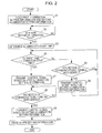
- Fig. 2 is a flowchart describing the operation of the communications terminal 100 according to the first embodiment of the present disclosure.
- the illumination setting information management unit 5 holds first illumination setting information and second illumination setting information.
- the input unit 1 accepts input of the first illumination setting information and the second illumination setting information from the user.
- the illumination setting information management unit 5 holds the first illumination setting information and the second illumination setting information accepted by the input unit 1.
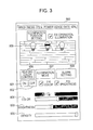
- Fig. 3 is a diagram illustrating an example of an illumination setting window for setting the second illumination setting information.
- the illumination setting window 600 illustrated in Fig. 3 includes an ON button 601, an OFF button 602, a brightness adjuster 603, a color adjuster 604, a density adjuster 605, a color control button 606, an illumination mode button 607, an alarm setting button 608, and one or more target illumination device selection buttons 609.
- the ON button 601 is used to turn on the illumination device 200. Upon pressing (touching) of the ON button 601, the illumination control unit 6 transmits a control signal for turning on the illumination device 200 to the illumination device 200.
- the OFF button 602 is used to turn off the illumination device 200. Upon pressing (touching) of the OFF button 602, the illumination control unit 6 transmits a control signal for turning off the illumination device 200 to the illumination device 200.
- the brightness adjuster 603 is used to adjust the brightness (illuminance) of light emitted by the illumination device 200.
- the illumination setting information management unit 5 holds an illuminance of light corresponding to the position indicated by the brightness adjuster 603 as the second illumination setting information.
- the range of an illuminance of light settable by the input unit 1 is 0 to 100%, 100% corresponding to the maximum illuminance of the illumination device 200.
- a method for adjusting the brightness of light is not limited to the method for adjusting the brightness of light in accordance with the position indicated by the brightness adjuster 603.
- a method for adjusting the brightness of light in accordance with a value of an azimuth, an inclination angle, or a rotation angle that can be acquired by the inclination sensor mounted in the communications terminal 100 may be used.
- the color adjuster 604 is used to adjust the color (wavelength) of light emitted by the illumination device 200. Upon operating of the color adjuster 604, the illumination setting information management unit 5 holds a wavelength of light corresponding to the position indicated by the color adjuster 604 as the second illumination setting information.
- a method for adjusting the color of light is not limited to the method for adjusting the color of light in accordance with the position indicated by the color adjuster 604.
- a method for adjusting the color of light in accordance with a value of an azimuth, an inclination angle, or a rotation angle that can be acquired by the inclination sensor mounted in the communications terminal 100 may be used.
- the density adjustor 605 is used to adjust the density (wavelength) of light emitted by the illumination device 200.
- the illumination setting information management unit 5 holds a wavelength of light corresponding to the position indicated by the density adjuster 605 as the second illumination setting information.
- the wavelength of the light changes.
- the wavelength of light settable by using the input unit 1 ranges from a wavelength corresponding to purple (for example, 380 nm) to a wavelength corresponding to red (for example, 800 nm).
- a method for adjusting the density of light is not limited to the method for adjusting the density of light in accordance with the position indicated by the density adjuster 605.
- a method for adjusting the density of light in accordance with a value of an azimuth, an inclination angle, or a rotation angle that can be acquired by the inclination sensor mounted in the communications terminal 100 may be used.
- the color control button 606 is used to emit light of a preset certain color (wavelength). Upon pressing (touching) of the color control button 606, the illumination control unit 6 transmits a control signal to the illumination device 200, the control signal causing the illumination device 200 to emit light of a preset certain color (wavelength). In Fig. 3 , upon selection of the color control button 606, a control signal for emitting light of a wavelength having a healing effect is transmitted to the illumination device 200.
- the illumination mode button 607 is used to emit light in a preset illumination mode. Upon pressing (touching) of the illumination mode button 607, an illumination mode setting window is displayed.
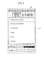
- FIG. 4 is a diagram illustrating an example of the illumination mode setting window.
- an illumination mode setting window 610 includes a selection image 611 for selecting a desired illumination mode from among a plurality of illumination modes corresponding to situations of the user.
- the selection image 611 shows a plurality of illumination modes, and the user presses (touches) a desired illumination mode among the plurality of displayed illumination modes.
- the selection image 611 illustrated in Fig. 4 shows illumination modes "reading/housework", “TV/Internet”, “dining", “relax”, and “refresh”. Setting values of illuminances and wavelengths corresponding to these illumination modes are stored in advance.
- the illumination setting information management unit 5 holds the illuminance and wavelength of light corresponding to the selected illumination mode as the second illumination setting information.
- the names of such illumination modes and the setting values of the illuminances and wavelengths corresponding to the illumination modes may be set by the user in advance.
- the alarm setting button 608 is used to set a time at which the user will wake up. Upon pressing (touching) of the alarm setting button 608, an alarm setting window is displayed.
- Each of the target illumination device selection buttons 609 is used to select a target illumination device for which illumination setting information is to be input. Upon pressing (touching) of one of the target illumination device selection buttons 609, the illumination device corresponding to the pressed target illumination device selection button 609 is selected as a target of setting.
- a method for selecting one of the target illumination device selection buttons 609 is not limited to the method for pressing (touching) the target illumination device selection button 609.
- a method for selecting one of the target illumination device selection buttons 609 in accordance with a value of an azimuth, an inclination angle, or a rotation angle that can be acquired by the inclination sensor mounted in the communications terminal 100 may be used.
- the number of target illumination device selection buttons 609 corresponds to the number of illumination devices registered in advance as illumination devices for which the setting can be operated on the illumination setting window. In the example illustrated in Fig. 3 , three illumination devices are registered as illumination devices for which the setting can be operated on the illumination setting window, and three target illumination device selection buttons 609 are displayed.
- a name or image desired by the user may be registered for each of the target illumination device selection buttons 609, and the registered name or image may be displayed in association with the target illumination device selection button 609.
- each of the target illumination device selection buttons 609 is arranged, for example, the user may press (touch) the target illumination device selection button 609 for a certain period (for example, three seconds), and then move the target illumination device selection button 609 while continuously pressing it, thereby moving the target illumination device selection button 609 to a desired position.
- a certain period for example, three seconds
- a plurality of the target illumination device selection buttons 609 may be simultaneously selected by continuously pressing (touching) them for a certain period (for example, two seconds), so as to collectively set illumination setting information for the plurality of illumination devices.
- the first illumination setting information can also be set using setting windows similar to those illustrated in Figs. 3 and 4 .
- Fig. 5 is a diagram illustrating an example of an alarm setting window.
- an alarm setting window 620 includes a wake-up time input image 621 for inputting a time at which the user will wake up.
- the wake-up time input image 621 shows a wake-up time, and the user inputs a desired wake-up time.
- the alarm setting information management unit 2 Upon pressing (touching) of a set button 622 after a wake-up time has been input, the alarm setting information management unit 2 holds the input wake-up time as alarm setting information.
- a cancel button 623 input of the wake-up time is canceled, and the illumination setting window 600 illustrated in Fig. 3 is displayed.
- the illumination setting information management unit 5 holds an input maximum illuminance value as the first illumination setting information.
- the illumination setting information management unit 5 may hold a predetermined maximum illuminance value as the first illumination setting information.
- step S2 the illumination control unit 6 judges whether or not alarm setting information is held by the alarm setting information management unit 2. In a case where it is judged that alarm setting information is not held (NO in step S2), a standby state continues until alarm setting information is held, and step S2 is repeatedly performed.
- step S3 the illumination control unit 6 determines an illumination start time on the basis of the alarm setting information.
- the illumination control unit 6 determines, as an illumination start time, a time a certain period (for example, one hour) before the user's wake-up time represented by the alarm setting information.
- the determined illumination start time is stored in a memory (not illustrated).
- the certain period is a period from when the illuminance value of light emitted by the illumination device 200 is 0 to when the illuminance value reaches the maximum illuminance value.
- the certain period may be a predetermined value, or may be set by the user.
- the illumination control unit 6 may determine the wake-up time represented by the alarm setting information to be an illumination start time. Also, the illumination control unit 6 may determine an illumination start time on the basis of automatic startup setting information about an electronic device connected to a network. For example, a time a certain period after a power-ON timer start time of an air conditioner is determined to be an illumination start time. In this case, it is not necessary to judge in step S2 whether or not alarm setting information is held. Alternatively, an illumination start time may be set in advance by the user. In this case, it is not necessary to judge in step S2 whether or not alarm setting information is held, and it is not necessary to determine an illumination start time in step S3.
- step S4 the illumination control unit 6 judges whether or not the current time matches the illumination start time.
- the communications terminal 100 has a clock function and thus the illumination control unit 6 is capable of acquiring the current time.
- the process proceeds to step S5, where the illumination control unit 6 judges whether or not a motion of the communications terminal 100 has been sensed by the terminal state sensing unit 4.
- the terminal state sensing unit 4 senses a motion of the communications terminal 100 caused by an action of the user.
- a motion of the communications terminal 100 caused by an action of the user is, for example, a motion of the communications terminal 100 when the user picks up the communications terminal 100, or a motion of the communications terminal 100 when the user operates the communications terminal 100.
- the communications terminal 100 has a vibration function for notifying the user of receipt of something by using vibration.
- the terminal state sensing unit 4 needs to sense a motion of the communications terminal 100 caused by an action of the user and vibration of the vibration function by distinguishing them from each other.
- Motion data representing a motion of the communications terminal 100 caused by an action of the user and vibration pattern data about the vibration function are represented by, for example, a history of change over a certain period in values of an azimuth, an inclination angle, and a rotation angle that can be acquired by the inclination sensor mounted in the communications terminal 100.
- motion data representing a motion of the communications terminal 100 caused by an action of the user and vibration pattern data about the vibration function are represented by a history of change over a certain period in values of an azimuth, an inclination angle, and a rotation angle that can be calculated by combining values that can be acquired by a geomagnetic sensor and an acceleration sensor mounted in the communications terminal 100.
- the communications terminal 100 stores a certain number of pieces of vibration pattern data about the vibration function that operates in the communications terminal 100, for example.
- the terminal state sensing unit 4 judges whether or not the degree of match between motion data representing a motion of the communications terminal 100 caused at certain timing and vibration pattern data that is stored in advance in the communications terminal 100 is lower than or equal to a certain threshold. In a case where the degree of match is lower than or equal to the certain threshold, the terminal state sensing unit 4 judges that the motion of the communications terminal 100 is a motion caused by an action of the user.
- the communications terminal 100 accepts input of a certain number of pieces of motion data corresponding to motions of the communications terminal 100 that are daily caused by the user, and stores the accepted pieces of motion data of the communications terminal 100 in the communications terminal 100.
- the terminal state sensing unit 4 judges whether or not the degree of match between motion data representing a motion of the communications terminal 100 caused at certain timing and motion data stored in the communications terminal 100 is higher than or equal to a certain threshold. In a case where the degree of match is higher than or equal to the certain threshold, the terminal state sensing unit 4 judges that the motion of the communications terminal 100 is a motion caused by an action of the user.
- the communication unit 7 may receive, for example, earthquake bulletin information from an earthquake bulletin database, and the terminal state sensing unit 4 may judge that a motion of the communications terminal 100 caused within a certain period from when the earthquake bulletin information is received is not a motion of the communications terminal 100 caused by an action of the user.
- a motion of the communications terminal 100 caused by an action of the user is likely to take shorter time than vibration caused by the vibration function or vibration caused by an earthquake.
- the terminal state sensing unit 4 may judge that a motion of the communications terminal 100 is a motion caused by an action of the user in a case where the amount of change in value of motion data of the communications terminal 100 becomes a certain threshold or less, or becomes zero within a certain period from when the motion of the communications terminal 100 starts.
- the alarm control unit 3 may perform control to output only an alarm and not to operate the vibration function at the wake-up time represented by the alarm setting information. Accordingly, vibration generated by the vibration function is not wrongly judged as a motion of the communications terminal 100 caused by an action of the user. As a result, a judgment accuracy for a motion of the communications terminal 100 caused by an action of the user can be enhanced.
- the terminal state sensing unit 4 may judge a motion of the communications terminal 100 caused by an action of the user by using the above-described methods in combination.
- step S5 can also be used to determine an illumination start time. While the user is sleeping, it is highly possible that a motion of the communications terminal 100 is not sensed. Further, the user may habitually operate the communications terminal 100 before bedtime. Thus, an illumination start time can be determined on the basis of an elapsed time since a motion of the communications terminal 100 is sensed last time. For example, eight hours after a motion of the communications terminal 100 is sensed last time may be determined to be an illumination start time. In this case, it is not necessary to judge whether or not alarm setting information is held (step S2), and it is not necessary to newly determine an illumination start time (step S3).
- step S5 the process proceeds to step S6, where the illumination control unit 6 reads out the second illumination setting information from the illumination setting information management unit 5, generates a control signal based on the read second illumination setting information, and transmits the generated control signal based on the second illumination setting information to the illumination device 200 via the communication unit 7.
- the communication unit 21 of the illumination device 200 receives the control signal based on the second illumination setting information.
- the operation control unit 22 emits light in accordance with the control signal that is based on the second illumination setting information and that has been received by the communication unit 21.
- the second illumination setting information represents a setting value of at least one of an illuminance, a wavelength, and a lighting pattern of the illumination device 200 after awakening.
- the operation control unit 22 emits light in accordance with a setting value of at least one of the illuminance, wavelength, and lighting pattern.
- step S6 In a case where the control signal based on the second illumination setting information is transmitted to the illumination device 200 in step S6, or in a case where it is judged in step S5 that a motion of the communications terminal 100 has not been sensed (NO in step S5), the process returns to step S4.
- the illumination device 200 lights up in accordance with the control signal based on the second illumination setting information. For example, in a case where the user wakes up at midnight and picks up the communications terminal 100, a motion of the communications terminal 100 is sensed before the illumination start time. In such a case, the control signal based on the second illumination setting information is transmitted to the illumination device 200, and the illumination device 200 lights up in accordance with the control signal based on the second illumination setting information. After that, the illumination device 200 is turned off when the user goes to bed again. That is, after step S6 has been performed and the illumination device 200 has been turned on, the illumination device 200 is turned off by the user.
- step S6 a process of judging whether or not the illumination device 200 has been turned off by the user may be performed.
- the communication unit 21 of the illumination device 200 transmits a signal indicating that the illumination device 200 has been turned off to the communications terminal 100, and the communication unit 7 of the communications terminal 100 receives the signal indicating that the illumination device 200 has been turned off.
- the illumination control unit 6 judges whether or not the signal indicating that the illumination device 200 has been turned off has been received. In a case where the signal indicating that the illumination device 200 has been turned off has been received, the process proceeds to step S4. In a case where the signal indicating that the illumination device 200 has been turned off has not been received, a standby state occurs, and the judgment is repeatedly performed until the signal indicating that the illumination device 200 has been turned off is received.
- the illumination control unit 6 transmits the control signal based on the second illumination setting information to the illumination device 200 in step S6, but the present disclosure is not particularly limited thereto.
- the illumination control unit 6 may transmit a control signal based on certain illumination setting information, which is different from the first illumination setting information and the second illumination setting information, to the illumination device 200 in step S6.
- the certain illumination setting information is information for illuminating a space in a case where the user wakes up before the illumination start time.
- the certain illumination setting information includes an illuminance of 0 (no illumination) to 50% of the maximum illuminance of the illumination device 200.
- the certain illumination setting information is held by the illumination setting information management unit 5 in step S1.
- the terminal state sensing unit 4 may sense a motion of the communications terminal 100 in accordance with a trigger of the motion in step S5, and may transmit a control signal based on illumination setting information other than the second illumination setting information corresponding to the trigger to the illumination device 200 in step S6.
- the communications terminal 100 receives a mail or a call
- the communications terminal 100 makes a motion of a certain pattern (for example, vibrates).
- the terminal state sensing unit 4 senses the motion of the certain pattern of the communications terminal 100 in step S5, and the illumination control unit 6 transmits a control signal based on illumination setting information corresponding to the certain motion pattern to the illumination device 200.
- the relationship between the trigger of the motion of the communications terminal 100 and the illumination setting information related to step S6 is stored in a memory of the communications terminal 100. Also, the illumination setting information related to step S6 is held by the illumination setting information management unit 5 in step S1.
- step S4 In a case where it is judged in step S4 that the current time matches the illumination start time (YES in step S4), the process proceeds to step S7, where the illumination control unit 6 reads out the first illumination setting information from the illumination setting information management unit 5, generates a control signal based on the read first illumination setting information, and transmits the generated control signal based on the first illumination setting information to the illumination device 200 via the communication unit 7.
- the communication unit 21 of the illumination device 200 receives the control signal based on the first illumination setting information.
- the operation control unit 22 emits light in accordance with the control signal that is based on the first illumination setting information and that has been received by the communication unit 21.
- the operation control unit 22 gradually changes the illuminance from 0 to the maximum illuminance value represented by the first illumination setting information during a period from the illumination start time to the wake-up time.
- the illuminance of the illumination device 200 linearly changes from 0 to the maximum illuminance value, but the present disclosure is not limited thereto, and the illuminance of the illumination device 200 may curvilinearly change from 0 to the maximum illuminance value.
- the first illumination setting information may include information indicating how the illuminance is to be changed.
- step S8 the illumination control unit 6 judges whether or not a motion of the communications terminal 100 has been sensed by the terminal state sensing unit 4.
- the operation performed in step S8 is the same as that performed in step S5.
- a standby state continues until a motion of the communications terminal 100 is sensed, and step S8 is repeatedly performed.
- step S8 the process proceeds to step S9, where the illumination control unit 6 reads out the second illumination setting information from the illumination setting information management unit 5, generates a control signal based on the read second illumination setting information, and transmits the generated control signal based on the second illumination setting information to the illumination device 200 via the communication unit 7.
- step S10 the alarm setting information management unit 2 erases the alarm setting information stored therein.
- the alarm setting information management unit 2 keeps holding the alarm setting information.
- the alarm setting information management unit 2 erases the alarm setting information.
- a control signal based on the second illumination setting information that is used to set an illumination state of the illumination device 200 in a space after the user wakes up is transmitted to the illumination device 200. Accordingly, with the motion of the communications terminal 100, it can be easily detected that the user has woken up, and the illumination device 200 can be easily controlled after the user has woken up.
- Fig. 6 is a diagram illustrating the configuration of an illumination control system according to a second embodiment of the present disclosure.
- the illumination control system illustrated in Fig. 6 includes the communications terminal 100, the illumination device 200, and a server 400.
- the same parts as those of the illumination control system according to the first embodiment are denoted by the same reference numerals, and the description thereof is omitted.
- the communications terminal 100 includes the input unit 1, the alarm setting information management unit 2, the alarm control unit 3, the terminal state sensing unit 4, the illumination setting information management unit 5, the illumination control unit 6, the communication unit 7, and an illumination setting item determination unit 8.
- the illumination device 200 includes the communication unit 21 and the operation control unit 22.
- the server 400 is connected to the communications terminal 100 via the network 300 so as to be capable of communicating with the communications terminal 100.
- the server 400 includes a power information management unit 41 and a communication unit 42.
- the power information management unit 41 of the server 400 manages power usage information representing the power usage in an area in which the illumination device 200 is provided, and electricity fee information representing the electricity fees in individual certain time slots in the area in which the illumination device 200 is provided.
- the communication unit 42 transmits the power usage information or the electricity fee information managed by the power information management unit 41 to the communications terminal 100.
- the communication unit 7 of the communications terminal 100 receives the power usage information or the electricity fee information transmitted by the server 400.
- the illumination setting item determination unit 8 determines the range of an illuminance settable in the communications terminal 100 or the range of a wavelength settable in the communications terminal 100, on the basis of the power usage information or the electricity fee information received by the communication unit 7.
- the illumination setting item determination unit 8 decreases the upper limit value of a settable illuminance, or makes it possible to set only a wavelength corresponding to a color expressed by a single light source, such as red, blue, or green, for example.
- the illumination setting item determination unit 8 increases the upper limit value of a settable illuminance, or makes it possible to set a wavelength corresponding to a color expressed by a plurality of light sources, such as white, yellow, or purple, for example.
- the correspondence between the power usage information or the electricity fee information, and the range of an illuminance or wavelength may be set by the user in advance.
- the input unit 1 accepts input of an illuminance or a wavelength within the range determined by the illumination setting item determination unit 8.
- the server 400 may transmit only any one of the power usage information and the electricity fee information to the communications terminal 100, and the communications terminal 100 may receive only any one of the power usage information and the electricity fee information transmitted by the server 400.
- the server 400 may transmit both of the power usage information and the electricity fee information to the communications terminal 100, and the communications terminal 100 may receive both of the power usage information and the electricity fee information transmitted by the server 400.
- the illumination setting item determination unit 8 determines the range of an illuminance or wavelength in consideration of both of the received power usage information and electricity fee information.
- the second embodiment is the same as the first embodiment except that the range of an illuminance or wavelength settable in the communications terminal 100 is determined on the basis of power usage information or electricity fee information, and thus any more detailed description is omitted.
- the alarm setting information management unit 2, the illumination setting information management unit 5, the illumination control unit 6, and the illumination setting item determination unit 8 illustrated in Fig. 6 may be provided in a server that is different from the server 400 and is connected to the communications terminal 100 so as to be capable of communicating with the communications terminal 100, not in the communications terminal 100.
- Fig. 7 is a diagram illustrating the configuration of an illumination control system according to a third embodiment of the present disclosure.
- the illumination control system illustrated in Fig. 7 includes the communications terminal 100 and the illumination device 200.
- the same parts as those in the illumination control systems according to the first and second embodiments are denoted by the same reference numerals, and the description thereof is omitted.
- the communications terminal 100 includes the input unit 1, the alarm setting information management unit 2, the alarm control unit 3, the terminal state sensing unit 4, the illumination setting information management unit 5, the illumination control unit 6, the communication unit 7, the illumination setting item determination unit 8, and an illuminance measurement unit 9.
- the illumination device 200 includes the communication unit 21 and the operation control unit 22.
- the illuminance measurement unit 9 measures an illuminance around the illumination device 200.
- the illuminance measurement unit 9 measures, for example, an illuminance around the illumination device 200 at a user's wake-up time.
- the illumination setting item determination unit 8 determines the range of an illuminance settable in the communications terminal 100, or the range of a wavelength settable in the communications terminal 100, on the basis of an ambient illuminance measured by the illuminance measurement unit 9.
- the illumination setting item determination unit 8 decreases the upper limit value of a settable illuminance, or makes it possible to set only a wavelength corresponding to a color of low density.
- the illumination setting item determination unit 8 increases the upper limit value of a settable illuminance, or makes it possible to set a wavelength corresponding to a color of high density.
- the correspondence between an ambient illuminance and the range of an illuminance or wavelength may be set by the user in advance.
- the input unit 1 accepts input of an illuminance or a wavelength within the range determined by the illumination setting item determination unit 8.
- the communications terminal 100 includes the illuminance measurement unit 9, but the present disclosure is not limited thereto.
- the illumination device 200 may include the illuminance measurement unit 9.
- an electric device other than the communications terminal 100 and the illumination device 200 may include the illuminance measurement unit 9 as long as the electric device exists within a space illuminated by the illumination device 200.
- the illumination control system may include an illuminance measurement device for measuring the illuminance of the illumination device 200.
- the third embodiment is the same as the first embodiment except that the upper limit value of an illuminance settable in the communications terminal 100 is determined on the basis of an ambient illuminance measured by the illuminance measurement unit 9, and thus any more detailed description is omitted.
- the alarm setting information management unit 2, the illumination setting information management unit 5, the illumination control unit 6, and the illumination setting item determination unit 8 illustrated in Fig. 7 may be provided in a server connected to the communications terminal 100 so as to be capable of communicating with the communications terminal 100, not in the communications terminal 100.
- Fig. 8 is a diagram illustrating the configuration of an illumination control system according to a fourth embodiment of the present disclosure.
- the illumination control system illustrated in Fig. 8 includes the communications terminal 100 and the illumination device 200.
- the same parts as those in the illumination control systems according to the first to third embodiments are denoted by the same reference numerals, and the description thereof is omitted.
- the communications terminal 100 includes the input unit 1, the alarm setting information management unit 2, the alarm control unit 3, the terminal state sensing unit 4, the illumination control unit 6, the communication unit 7, the illumination setting item determination unit 8, and an illumination setting information management unit 10.
- the illumination device 200 includes the communication unit 21 and the operation control unit 22.
- the input unit 1 accepts setting of an illumination mode from the user.
- the illumination mode is set by using, for example, the illumination mode setting window 610 illustrated in Fig. 4 .
- the input unit 1 accepts setting of a desired illumination mode corresponding to a situation of the user among a plurality of illumination modes representing situations of the user.
- an illumination mode corresponding to a situation of the user for example, "reading/housework”, “TV/Internet”, “dining”, “relax”, or "refresh" is set.
- the illumination setting item determination unit 8 determines the range of an illuminance settable in the communications terminal 100 or the range of a wavelength settable in the communications terminal 100, on the basis of the illumination mode accepted by the input unit 1. Each illumination mode is associated with the range of an illuminance settable in the communications terminal 100 or the range of a wavelength settable in the communications terminal 100.
- a memory of the communications terminal 100 (not illustrated) stores, in advance, a table in which illumination modes are associated with the ranges of illuminances settable in the communications terminal 100 and the ranges of wavelengths settable in the communications terminal 100.
- the illumination setting item determination unit 8 determines, using the table stored in the memory in advance, the range of an illuminance or the range of a wavelength corresponding to the illumination mode accepted by the input unit 1.
- the correspondence between the illumination modes and the ranges of illuminances or wavelengths may be set by the user in advance.
- the input unit 1 accepts input of an illuminance so that the illuminance is within the range determined by the illumination setting item determination unit 8, and also accepts input of a wavelength so that the wavelength is within the range determined by the illumination setting item determination unit 8.
- the illumination setting information management unit 10 holds, as the second illumination setting information, the illuminance and wavelength that have been set so as to be within the range of an illuminance or the range of a wavelength determined by the illumination setting item determination unit 8.
- the fourth embodiment is the same as the first embodiment except that the range of an illuminance settable in the communications terminal 100 or the range of a wavelength settable in the communications terminal 100 is determined on the basis of an illumination mode, and thus any more detailed description is omitted.
- the illumination setting item determination unit 8 determines any one of the range of an illuminance settable in the communications terminal 100 and the range of a wavelength settable in the communications terminal 100, but the present disclosure is not limited thereto. Alternatively, the illumination setting item determination unit 8 may determine both of the range of an illuminance settable in the communications terminal 100 and the range of a wavelength settable in the communications terminal 100.
- the alarm setting information management unit 2, the illumination setting information management unit 10, the illumination control unit 6, and the illumination setting item determination unit 8 illustrated in Fig. 8 may be included in a server connected to the communications terminal 100 so as to be capable of communicating with the communications terminal 100, not in the communications terminal 100.
- Fig. 9 is a diagram illustrating the configuration of an illumination control system according to a fifth embodiment of the present disclosure.
- the illumination control system illustrated in Fig. 9 includes the communications terminal 100 and the illumination device 200.
- the same parts as those in the illumination control systems according to the first to fourth embodiments are denoted by the same reference numerals, and the description thereof is omitted.
- the communications terminal 100 includes the input unit 1, the alarm setting information management unit 2, the alarm control unit 3, the terminal state sensing unit 4, the illumination setting information management unit 5, the illumination control unit 6, the communication unit 7, and the illuminance measurement unit 9.
- the illumination device 200 includes the communication unit 21 and the operation control unit 22.
- the illuminance measurement unit 9 measures an illuminance around the illumination device 200.
- the illuminance measurement unit 9 measures, for example, an illuminance around the illumination device 200 at a user's wake-up time.
- the input unit 1 accepts setting of an illumination mode from the user.
- the illumination mode is set by using, for example, the illumination mode setting window 610 illustrated in Fig. 4 .
- the input unit 1 accepts setting of a desired illumination mode corresponding to a situation of the user among a plurality of illumination modes representing situations of the user.
- an illumination mode corresponding to a situation of the user for example, "reading/housework”, “TV/Internet”, “dining”, “relax”, or "refresh" is set.
- the illumination control unit 6 determines the illuminance or wavelength included in the second illumination setting information on the basis of the ambient illuminance measured by the illuminance measurement unit 9 and the illumination mode accepted by the input unit 1.
- An illuminance or wavelength is associated with each combination of an illumination mode and an ambient illuminance.
- the memory of the communications terminal 100 (not illustrated) stores, in advance, a table in which illumination modes, ambient illuminances, and illuminances or wavelengths are associated with one another.
- the illumination control unit 6 determines the illuminance or wavelength corresponding to the ambient illuminance measured by the illuminance measurement unit 9 and the illumination mode accepted by the input unit 1, by using the table stored in the memory in advance.
- the correspondence among the illumination modes, ambient illuminances, and illuminances or wavelengths may be set by the user in advance.
- the illuminance control unit 6 stores the determined illuminance or wavelength as the second illumination setting information in the illumination setting information management unit 5.
- the fifth embodiment is the same as the first embodiment except that the illuminance or wavelength included in the second illumination setting information is determined on the basis of an ambient illuminance and an illumination mode, and thus any more detailed description is omitted.
- the illumination control unit 6 determines any one of an illuminance and a wavelength, but the present disclosure is not limited thereto. Alternatively, the illumination control unit 6 may determine both of an illuminance and a wavelength.
- Fig. 10 is a diagram illustrating the configuration of an illumination control system according to a sixth embodiment of the present disclosure.
- the illumination control system illustrated in Fig. 10 includes the communications terminal 100, the illumination device 200, and a human presence sensing device 500.
- the same parts as those in the illumination control systems according to the first to fifth embodiments are denoted by the same reference numerals, and the description thereof is omitted.
- the communications terminal 100 includes the input unit 1, the alarm setting information management unit 2, the alarm control unit 3, the terminal state sensing unit 4, the illumination setting information management unit 5, the illumination control unit 6, and the communication unit 7.
- the illumination device 200 includes the communication unit 21 and the operation control unit 22.
- the human presence sensing device 500 is connected to the communications terminal 100 via the network 300 so as to be capable of communicating with the communications terminal 100.
- the human presence sensing device 500 includes a human state sensing unit 51 and a communication unit 52.
- the human state sensing unit 51 senses sleeping states of a plurality of users in a space illuminated by the illumination device 200.
- the human state sensing unit 51 includes a plurality of thermal image cameras that sense changes in an amount of infrared emitted by users and that are provided for the individual users.
- the human state sensing unit 51 analyzes images output from the plurality of thermal image cameras, identifies the differences between sleeping body temperatures and waking body temperatures of the individual users, and judges whether or not the individual users are sleeping.
- the images acquired from the individual thermal image cameras are associated with the individual users, and the sleeping states of the individual users can be sensed.
- the communication unit 52 transmits the sleeping states of the plurality of users sensed by the human state sensing unit 51 to the communications terminal 100.
- the communication unit 7 of the communications terminal 100 receives the sleeping states of the plurality of users transmitted by the human presence sensing device 500.
- the illumination control unit 6 judges whether or not another user existing in the same space as the user who owns the communications terminal 100 is sleeping. At this time, the illumination control unit 6 judges whether or not another user is sleeping in accordance with the sleeping states of the individual users received by the communication unit 7.
- the illumination control unit 6 causes the illuminance, wavelength, or lighting pattern included in the second illumination setting information in a case where it is judged that another user is sleeping to be different from that in a case where it is judged that another user is not sleeping. For example, in a case where it is judged that another user is not sleeping, the illumination control unit 6 generates a control signal based on the illuminance included in the second illumination setting information. On the other hand, in a case where it is judged that another user is sleeping, the illumination control unit 6 generates a control signal based on an illuminance lower than the illuminance included in the second illumination setting information.
- the illumination control unit 6 in a case where it is judged that another user is not sleeping, the illumination control unit 6 generates a control signal based on the wavelength included in the second illumination setting information. On the other hand, in a case where it is judged that another user is sleeping, the illumination control unit 6 generates a control signal based on a wavelength larger than the wavelength included in the second illumination setting information.
- the illumination control unit 6 may generate a control signal for causing the illumination device 200 to light up for a certain period and to be turned off after the certain period has elapsed, as a control signal based on the second illumination setting information, and transmit the control signal.
- the illuminance, wavelength, or lighting pattern for a case where it is judged that another user is sleeping may be set by the user in advance.
- the sixth embodiment is the same as the first embodiment except that the illuminance, wavelength, or lighting pattern included in the second illumination setting information in a case where it is judged that another user is sleeping is different from that in a case where it is judged that another user is not sleeping, and thus any more detailed description is omitted.
- Fig. 11 is a diagram illustrating the configuration of an illumination control system according to a seventh embodiment of the present disclosure.
- the illumination control system illustrated in Fig. 11 includes the communications terminal 100, a first illumination device 200a, a second illumination device 200b, and the human presence sensing device 500.
- the same parts as those in the illumination control systems according to the first to sixth embodiments are denoted by the same reference numerals, and the description thereof is omitted.
- the communications terminal 100 includes the input unit 1, the alarm setting information management unit 2, the alarm control unit 3, the terminal state sensing unit 4, the illumination setting information management unit 5, the illumination control unit 6, and the communication unit 7.
- the first illumination device 200a illuminates a first user.
- the first illumination device 200a includes the communication unit 21 and the operation control unit 22.
- the second illumination device 200b illuminates a second user who is in the same space as the first user.
- the configuration of the second illumination device 200b is the same as the first illumination device 200a, and thus the description thereof is omitted.
- the human presence sensing device 500 is connected to the communications terminal 100 via the network 300 so as to be capable of communicating with the communications terminal 100.
- the human presence sensing device 500 includes the human state sensing unit 51 and the communication unit 52.
- the human state sensing unit 51 senses the sleeping states of the first and second users in the spaces illuminated by the illumination devices 200a and 200b.
- the human state sensing unit 51 includes first and second thermal image cameras that are provided for the first and second users and that sense changes in amounts of infrared emitted from the individual users.
- the human state sensing unit 51 analyzes the images output from the first and second thermal image cameras, identifies the differences between sleeping body temperatures and waking body temperatures of the individual users, and judges whether or not the individual users are sleeping.
- the images acquired from the individual thermal image cameras are associated with the individual users, and the sleeping states of the individual users can be sensed.
- the communication unit 52 transmits the sleeping states of the first and second users sensed by the human state sensing unit 51 to the communications terminal 100.
- the communication unit 7 of the communications terminal 100 receives the sleeping states of the first and second users transmitted from the human presence sensing device 500.
- the illumination control unit 6 judges whether or not the second user who is in the same space as the first user who owns the communications terminal 100 is sleeping. At this time, the illumination control unit 6 judges whether or not the second user is sleeping in accordance with the sleeping states of the individual users received by the communication unit 7.
- the illumination control unit 6 transmits a control signal based on the second illumination setting information to only the first illumination device 200a. In a case where it is judged that the second user is not sleeping, the illumination control unit 6 transmits a control signal based on the second illumination setting information to the first illumination device 200a and the second illumination device 200b.
- the illumination device to which a control signal for illumination is to be transmitted in a case where it is judged that the second user is sleeping may be set by the user in advance.
- the seventh embodiment is the same as the first embodiment except that a control signal based on the second illumination setting information is transmitted to the first illumination device 200a in a case where it is judged that the second user is sleeping, and thus any more detailed description is omitted.
- Fig. 12 is a diagram illustrating the configuration of an illumination control system according to an eighth embodiment of the present disclosure.
- the illumination control system illustrated in Fig. 12 includes the communications terminal 100, the illumination device 200, and a server 401.
- the same parts as those in the illumination control systems according to the first to seventh embodiments are denoted by the same reference numerals, and the description thereof is omitted.
- the communications terminal 100 includes the input unit 1, the alarm setting information management unit 2, the alarm control unit 3, the terminal state sensing unit 4, the illumination setting information management unit 5, the illumination control unit 6, and the communication unit 7.
- the illumination device 200 includes the communication unit 21 and the operation control unit 22.
- the server 401 is connected to the communications terminal 100 via the network 300 so as to be capable of communicating with the communications terminal 100.
- the server 401 includes a meteorological information management unit 43 and the communication unit 42.
- the meteorological information management unit 43 manages meteorological information.
- the meteorological information includes, for example, weather forecast, probability of precipitation, minimum temperature, maximum temperature, airborne pollen level, amount of ultraviolet rays, and so forth.
- the communication unit 42 transmits the meteorological information managed by the meteorological information management unit 43 to the communications terminal 100.
- the communication unit 7 of the communications terminal 100 receives the meteorological information transmitted from the server 401.
- the illumination control unit 6 determines a setting value of at least one of the illuminance, wavelength, and lighting pattern included in the second illumination setting information, on the basis of the meteorological information received by the communication unit 7. For example, if the weather forecast for the day when the user wakes up is sunny, the illumination control unit 6 generates second illumination setting information including a certain illuminance and a wavelength corresponding to red, and stores the second illumination setting information in the illumination setting information management unit 5. For example, if the weather forecast for the day when the user wakes up is rainy, the illumination control unit 6 generates second illumination setting information including a certain illuminance and a wavelength corresponding to blue. In this way, the illumination control unit 6 determines a setting value of a certain illuminance and a setting value of a color (wavelength) corresponding to the weather forecast for the day when the user wakes up.
- the illumination control unit 6 may determine a setting value of a certain illuminance and a setting value of a color (wavelength) corresponding to the probability of precipitation of the day when the user wakes up, as the second illumination setting information.
- the illumination control unit 6 may determine a setting value of a certain illuminance and a setting value of a color (wavelength) corresponding to the difference between the minimum temperature of the day when the user wakes up and the minimum temperature of the previous day, as the second illumination setting information.
- the illumination control unit 6 may determine a setting value of a certain illuminance and a setting value of a color (wavelength) corresponding to the difference between the maximum temperature of the day when the user wakes up and the maximum temperature of the previous day, as the second illumination setting information.
- the illumination control unit 6 may determine a setting value of a certain illuminance and a setting value of a color (wavelength) corresponding to the airborne pollen level of the day when the user wakes up, as the second illumination setting information.
- the illumination control unit 6 may determine a setting value of a certain illuminance and a setting value of a color (wavelength) corresponding to the amount of ultraviolet rays of the day when the user wakes up, as the second illumination setting information.
- the illumination control unit 6 may determine a setting value of a certain illuminance and a setting value of a lighting pattern in which a light source blinks at certain intervals, as the second illumination setting information.
- the communications terminal 100 may determine the range of a settable illuminance or wavelength in the second illumination setting information on the basis of an ambient temperature of the illumination device 200 measured by the communications terminal 100. For example, in a case where the ambient temperature is higher than a certain reference temperature, the range of a settable illuminance is limited to a range of a lower illuminance than usual, and the range of a settable wavelength is limited to a range of a wavelength of cold colors. In a case where the ambient temperature is lower than the certain reference temperature, the range of a settable illuminance is limited to a range of a higher illuminance than usual, and the range of a settable wavelength is limited to a range of a wavelength of warm colors.
- the maximum illuminance of the illumination device 200 is 100%.
- the range of a normally settable illuminance is 0 to 100%, whereas the range of an illuminance limited to a lower range is 0 to 50%, and the range of an illuminance limited to a higher range is 50 to 100%, for example.
- the range of a normally settable wavelength is 300 to 800 nm.
- the range of a wavelength limited to cold colors is a range of a wavelength corresponding to the colors ranging from 10 PB to 10 BG in the Munsell color system
- the range of a wavelength limited to warm colors is a range of a wavelength corresponding to the colors ranging from 5 RP to 5 GY in the Munsell color system, for example.
- the correspondence between the meteorological information and the illuminance, wavelength, and lighting pattern of illumination may be set by the user in advance.
- the eighth embodiment is the same as the first embodiment except that a setting value of at least one of the illuminance, wavelength, and lighting pattern included in the second illumination setting information is determined on the basis of meteorological information, and thus any more detailed description is omitted.
- Fig. 13 is a diagram illustrating the configuration of an illumination control system according to a ninth embodiment of the present disclosure.
- the illumination control system illustrated in Fig. 13 includes the communications terminal 100, the illumination device 200, and the server 401.
- the same parts as those in the illumination control systems according to the first to eighth embodiments are denoted by the same reference numerals, and the description thereof is omitted.
- the communications terminal 100 includes the input unit 1, an alarm setting information management unit 11, the alarm control unit 3, the terminal state sensing unit 4, the illumination setting information management unit 5, the illumination control unit 6, and the communication unit 7.
- the illumination device 200 includes the communication unit 21 and the operation control unit 22.
- the server 401 includes the meteorological information management unit 43 and the communication unit 42.
- the alarm setting information management unit 11 determines alarm setting information on the basis of meteorological information received by the communication unit 7. For example, if the weather forecast for the day when the user wakes up is rainy, the alarm setting information management unit 11 moves the time represented by the currently held alarm setting information a certain period ahead. For example, in a case where the time represented by the currently held alarm setting information is 7 o'clock and where the weather forecast for the day when the user wakes up is rainy, the alarm setting information management unit 11 changes the time represented by the alarm setting information to 6 o'clock, which is one hour earlier, and holds the alarm setting information.
- the user can wake up earlier than the wake-up time that is set by the user in advance.
- the time represented by the alarm setting information may be moved ahead a predetermined certain period or a certain period set by the user.
- the certain period is stored in association with meteorological information (for example, weather forecast).
- the ninth embodiment is the same as the first embodiment except that alarm setting information is determined on the basis of meteorological information, and thus any more detailed description is omitted.
- Fig. 14 is a diagram illustrating the configuration of an illumination control system according to a tenth embodiment of the present disclosure.
- the illumination control system illustrated in Fig. 14 includes the communications terminal 100, the illumination device 200, and a server 403.
- the same parts as those in the illumination control systems according to the first to ninth embodiments are denoted by the same reference numerals, and the description thereof is omitted.
- the communications terminal 100 includes the input unit 1, an alarm setting information management unit 12, the alarm control unit 3, the terminal state sensing unit 4, the illumination setting information management unit 5, the illumination control unit 6, and the communication unit 7.
- the illumination device 200 includes the communication unit 21 and the operation control unit 22.
- the server 403 is connected to the communications terminal 100 via the network 300 so as to be capable of communicating with the communications terminal 100.
- the server 403 includes a schedule information management unit 45 and the communication unit 42.
- the schedule information management unit 45 manages schedule information representing a schedule of the user.
- the input unit 1 of the communications terminal 100 accepts input of a schedule from the user.
- the input schedule information is transmitted to the server 403 and is stored in the schedule information management unit 45.
- the communication unit 42 transmits the schedule information managed by the schedule information management unit 45 to the communications terminal 100.
- the schedule information includes a schedule start time representing the time at which the first event in the schedule of one day is performed.
- the communication unit 7 of the communications terminal 100 receives the schedule information transmitted from the server 403.
- the alarm setting information management unit 12 determines alarm setting information on the basis of the schedule information received by the communication unit 7.
- the alarm setting information management unit 12 holds, as alarm setting information, a time a certain period before the schedule start time included in the schedule information. For example, in a case where the schedule start time is 9 o'clock, the alarm setting information management unit 12 holds, as alarm setting information, 7 o'clock which is two hours before 9 o'clock, which is the schedule start time.
- alarm setting information is automatically set without inputting alarm setting information, and thus a user operation can be simplified.
- a time a predetermined certain period before the schedule start time may be set, or a time a certain period set by the user before the schedule start time may be set.
- the tenth embodiment is the same as the first embodiment except that alarm setting information is determined on the basis of schedule information, and thus any more detailed description is omitted.
- Fig. 15 is a diagram illustrating the configuration of an illumination control system according to an eleventh embodiment of the present disclosure.
- the illumination control system illustrated in Fig. 15 includes the communications terminal 100, the illumination device 200, and a server 404.
- the same parts as those in the illumination control systems according to the first to tenth embodiments are denoted by the same reference numerals, and the description thereof is omitted.
- the communications terminal 100 includes the input unit 1, the alarm setting information management unit 2, the alarm control unit 3, the terminal state sensing unit 4, the illumination setting information management unit 5, the illumination control unit 6, the communication unit 7, and a user identification information acquisition unit 13.
- the illumination device 200 includes the communication unit 21 and the operation control unit 22.
- the server 404 is connected to the communications terminal 100 via the network 300 so as to be capable of communicating with the communications terminal 100.
- the server 404 includes a user identification information management unit 46 and the communication unit 42.
- the user identification information management unit 46 manages user identification information for identifying the user.
- An example of user identification information is biological information such as fingerprint information or voice information.
- the user identification information management unit 46 stores user identification information together with a user ID.
- the user identification information may be character information such as a password.
- the communication unit 42 receives user identification information from the communications terminal 100, acquires a user ID corresponding to the received user identification information from the user identification information management unit 46, and transmits the user ID to the communications terminal 100.
- the user identification information acquisition unit 13 of the communications terminal 100 acquires user identification information for identifying one of a plurality of users.
- the user identification information is character information
- the user identification information acquisition unit 13 accepts input of the character information from the user, and acquires the character information input by the user.
- the user identification information acquisition unit 13 reads a fingerprint of the user, and acquires the read fingerprint information.
- the user identification information acquisition unit 13 acquires voice of the user, and converts the acquired analog voice to digital voice information.
- the illumination setting information management unit 5 manages second illumination setting information for each user.
- the second illumination setting information includes a plurality of pieces of second illumination setting information for a plurality of users.
- the illumination setting information management unit 5 stores a user ID and second illumination setting information in association with each other.
- the communication unit 7 transmits the user identification information acquired by the user identification information acquisition unit 13 to the server 404, and receives a user ID transmitted from the server 404.
- the illumination control unit 6 determines, on the basis of the acquired user identification information, a piece of second illumination setting information for one user among a plurality of pieces of second illumination setting information. That is, the illumination control unit 6 transmits the user identification information acquired by the user identification information acquisition unit 13 to the server 404, and reads out a piece of second illumination setting information corresponding to the user ID received by the communication unit 7 from the illumination setting information management unit 5. Also, the illumination control unit 6 transmits a control signal based on the piece of second illumination setting information to the illumination device 200.
- the input unit 1 of the communications terminal 100 accepts input of a user ID from the user, and the user identification information acquisition unit 13 acquires user identification information.
- the user ID and the user identification information are transmitted to the server 404, and are stored in the user identification information management unit 46 in association with each other.
- the eleventh embodiment is the same as the first embodiment except that a piece of second illumination setting information for one user is determined among a plurality of pieces of second illumination setting information on the basis of acquired user identification information, and thus any more detailed description is omitted.
- Fig. 16 is a diagram illustrating the configuration of an illumination control system according to a twelfth embodiment of the present disclosure.
- the illumination control system illustrated in Fig. 16 includes the communications terminal 100, the illumination device 200, and a server 405.
- the same parts as those in the illumination control systems according to the first to eleventh embodiments are denoted by the same reference numerals, and the description thereof is omitted.
- the communications terminal 100 includes the input unit 1, the alarm setting information management unit 2, the alarm control unit 3, the terminal state sensing unit 4, the illumination setting information management unit 5, the illumination control unit 6, and the communication unit 7.
- the illumination device 200 includes the communication unit 21 and the operation control unit 22.
- the server 405 is connected to the communications terminal 100 via the network 300 so as to be capable of communicating with the communications terminal 100.
- the server 405 includes an earthquake information management unit 47 and the communication unit 42.
- the earthquake information management unit 47 manages earthquake information indicating that an earthquake has occurred.
- the earthquake information is, for example, an earthquake bulletin provided by a meteorological agency or a weather forecast company.
- the communication unit 42 transmits the earthquake information managed by the earthquake information management unit 47 to the communications terminal 100.
- the communication unit 7 of the communications terminal 100 receives the earthquake information transmitted from the server 405.
- the illumination control unit 6 judges, on the basis of the received earthquake information, whether or not the motion of the communications terminal 100 is due to the user or the earthquake. In a case where it is judged that the motion of the communications terminal 100 is due to the earthquake, the illumination control unit 6 changes a setting value of at least one of the illuminance, wavelength, and lighting pattern included in the second illumination setting information to a specific setting value indicating that an earthquake has occurred. The illumination control unit 6 then transmits a control signal based on the second illumination setting information to the illumination device 200.
- the specific setting value is a setting value of at least one of an illuminance, a wavelength, and a lighting pattern for notifying the user that an earthquake has occurred.
- the specific setting value may be an illuminance or wavelength for awakening the user, or may be a lighting pattern for blinking a light source.
- the illumination setting information management unit 5 further holds earthquake illumination setting information (third illumination setting information) for setting an illumination state of the illumination device 200 in a space after an earthquake has occurred.
- the earthquake illumination setting information includes a setting value of at least one of the illumination, wavelength, and lighting pattern of the illumination device 200 after the occurrence of an earthquake.
- the earthquake illumination setting information represents a setting value of the illumination device 200 when the user wakes up after an earthquake has occurred.
- the earthquake illumination setting information may be an illuminance value for brightly illuminating a space to help the user evacuate, or may be a maximum illuminance value settable in the illumination device 200.
- the illuminance, wavelength, and lighting pattern of illumination for the time of the occurrence of an earthquake or after the occurrence of an earthquake may be set by the user in advance.
- the illumination control unit 6 After it is judged that the motion of the communications terminal 100 is due to an earthquake, if a motion of the communications terminal 100 is sensed, the illumination control unit 6 transmits a control signal based on the third illumination setting information to the illumination device 200.
- a trigger of changing a setting value of at least one of the illuminance, wavelength, and lighting pattern included in the second illumination setting information to a specific setting value is not limited to the occurrence of an earthquake.
- the communications terminal 100 may receive communication information, and a setting value of at least one of the illuminance, wavelength, and lighting pattern included in the second illumination setting information can be changed to a specific setting value on the basis of the received communication information. For example, in a case where the number of messages or comments received via a social networking service (SNS) application is larger than or equal to a certain number or where a message or comment transmitted from a specific person is received, the setting value may be changed to a specific setting value representing that fact.
- SNS social networking service
- the twelfth embodiment is the same as the first embodiment except that, in a case where it is judged that a motion of the communications terminal 100 is due to an earthquake, a setting value of at least one of the illuminance, wavelength, and lighting pattern included in the second illumination setting information is changed to a specific setting value indicating that an earthquake has occurred, and a control signal based on the second illumination setting information is transmitted to the illumination device 200, and in a case where a motion of the communications terminal 100 is sensed after it is judged that a motion of the communications terminal 100 is due to an earthquake, a control signal based on earthquake illumination setting information is transmitted to the illumination device 200.
- any more detailed description is omitted.
- Fig. 17 is a diagram illustrating the configuration of an illumination control system according to a thirteenth embodiment of the present disclosure.
- the illumination control system illustrated in Fig. 17 includes the communications terminal 100, the illumination device 200, and a server 406.
- the same parts as those in the illumination control systems according to the first to twelfth embodiments are denoted by the same reference numerals, and the description thereof is omitted.
- the communications terminal 100 includes the input unit 1, the alarm setting information management unit 2, the alarm control unit 3, the terminal state sensing unit 4, the illumination setting information management unit 5, the illumination control unit 6, and the communication unit 7.
- the illumination device 200 includes the communication unit 21 and the operation control unit 22.
- the server 406 is connected to the communications terminal 100 via the network 300 so as to be capable of communicating with the communications terminal 100.
- the server 406 includes a terminal state management unit 48, a bedtime determination unit 49, and the communication unit 42.
- the terminal state management unit 48 holds and manages log information representing a history of times at which a motion of the communications terminal 100 was sensed.
- the bedtime determination unit 49 determines a user's recommended bedtime on the basis of the log information managed by the terminal state management unit 48.
- the bedtime determination unit 49 calculates an average time in a certain period of the times at which a motion of the communications terminal 100 was sensed included in the log information, subtracts a certain hour from the calculated average time, and determines the result as a recommended bedtime.
- the certain period is a predetermined period, for example, one month from June to July of 2013, or 43 days as a total of Monday to Friday of June to July of 2013.
- the certain period may be set by the user in advance.
- the certain hour is a predetermined hour, for example, 7 hours.
- the certain hour may be set by the user in advance.
- the communication unit 42 receives, from the communications terminal 100, a time at which a motion of the communications terminal 100 was sensed, and outputs the received time at which a motion of the communications terminal 100 was sensed to the terminal state management unit 48. Also, the communication unit 42 transmits a recommended bedtime determined by the bedtime determination unit 49 to the communications terminal 100.
- the communication unit 7 of the communications terminal 100 receives the recommended bedtime transmitted from the server 406.
- the communication unit 7 outputs the received recommended bedtime to the alarm setting information management unit 2.
- the alarm setting information management unit 2 holds and manages the recommended bedtime received by the communication unit 7.
- the illumination setting information management unit 5 holds and manages sleeping illumination setting information (fourth illumination setting information) for setting an illumination state of the illumination device 200 in a space when the user goes to bed.
- the sleeping illumination setting information includes a setting value of at least one of the illuminance, wavelength, and lighting pattern of the illumination device 200.
- the illumination control unit 6 transmits a control signal based on the sleeping illumination setting information to the illumination device 200.
- the control signal based on the sleeping illumination setting information is a control signal for gradually changing (for example, decreasing) the illuminance of the illumination device 200, or a control signal for gradually changing the wavelength of the illumination device 200.
- the illumination control unit 6 gradually changes (for example, decreases) the illuminance from the recommended bedtime to an illumination end time. At this time, the illuminance at the recommended bedtime is an illuminance that does not prevent the user from falling asleep, for example, 500 lux or less.
- the illumination control unit 6 gradually changes the wavelength from the recommended bedtime to the illumination end time.
- the wavelength at the recommended bedtime is a wavelength that does not prevent the user from falling asleep, that is, a wavelength having weak light stimulation.
- the illuminance, wavelength, and lighting pattern of illumination at the recommended bedtime may be set by the user in advance.
- a setting value of at least one of the illuminance, wavelength, and lighting pattern included in the fourth illumination setting information may be set on the basis of the communication information received by the communications terminal 100. For example, in a case where the number of messages or comments received by the communications terminal 1 via an SNS application is larger than or equal to a certain number or where a message or comment transmitted from a specific person is received by the communications terminal 1, the setting value may be set to a specific setting value representing that fact.
- the bedtime determination unit 49 is provided in the server 406, but the present disclosure is not limited thereto.
- the communications terminal 100 may include the bedtime determination unit 49.
- the thirteenth embodiment is the same as the first embodiment except that a control signal based on sleeping illumination setting information is transmitted to the illumination device 200 when the current time becomes the recommended sleeping time, and thus any more detailed description is omitted.
- Fig. 18 is a diagram illustrating the configuration of an illumination control system according to a fourteenth embodiment of the present disclosure.
- the illumination control system illustrated in Fig. 18 includes the communications terminal 100, the illumination device 200, and a server 407.
- the same parts as those in the illumination control systems according to the first to thirteenth embodiments are denoted by the same reference numerals, and the description thereof is omitted.
- the communications terminal 100 includes the input unit 1, the alarm setting information management unit 2, the alarm control unit 3, the terminal state sensing unit 4, the illumination setting information management unit 5, the illumination control unit 6, and the communication unit 7.
- the illumination device 200 includes the communication unit 21 and the operation control unit 22.
- the server 407 is connected to the communications terminal 100 via the network 300 so as to be capable of communicating with the communications terminal 100.
- the server 407 includes the meteorological information management unit 43, the terminal state management unit 48, the bedtime determination unit 49, and the communication unit 42.
- the meteorological information management unit 43 manages meteorological information.
- the meteorological information includes, for example, weather forecast, probability of precipitation, minimum temperature, maximum temperature, airborne pollen level, amount of ultraviolet rays, and so forth.
- the terminal state management unit 48 holds and manages log information representing a history of times at which a motion of the communications terminal 100 was sensed.
- the bedtime determination unit 49 determines a user's recommended bedtime on the basis of the log information managed by the terminal state management unit 48.
- the communication unit 42 transmits the meteorological information managed by the meteorological information management unit 43 to the communications terminal 100. Also, the communication unit 42 receives, from the communications terminal 100, a time at which a motion of the communications terminal 100 was sensed, and outputs the received time at which a motion of the communications terminal 100 was sensed to the terminal state management unit 48. Also, the communication unit 42 transmits a recommended bedtime determined by the bedtime determination unit 49 to the communications terminal 100.
- the communication unit 7 of the communications terminal 100 receives the meteorological information transmitted from the server 407. Also, the communication unit 7 receives the recommended bedtime transmitted from the server 407.
- the alarm setting information management unit 2 holds and manages the recommended bedtime received by the communication unit 7.
- the illumination setting information management unit 5 holds and manages sleeping illumination setting information (fourth illumination setting information) for setting an illumination state of the illumination device 200 in a space when the user goes to bed.
- the sleeping illumination setting information includes a setting value of at least one of the illuminance, wavelength, and lighting pattern of the illumination device 200.
- the illumination control unit 6 determines a setting value of at least one of the illuminance, wavelength, and lighting pattern included in the sleeping illumination setting information, on the basis of the meteorological information received by the communication unit 7. For example, in a case where the weather forecast for the day after the day when the user goes to bed is sunny, the illumination control unit 6 generates sleeping illumination setting information including a certain illuminance and a wavelength corresponding to red, and stores the sleeping illumination setting information in the illumination setting information management unit 5. In a case where the weather forecast for the day after the day when the user goes to bed is rainy, the illumination control unit 6 generates sleeping illumination setting information including a certain illuminance and a wavelength corresponding to blue. In this way, the illumination control unit 6 determines a setting value of a certain illuminance and a setting value of a color (wavelength) corresponding to the weather forecast for the day after the day when the user goes to bed.
- the illumination control unit 6 may determine a setting value of a certain illuminance and a setting value of a color (wavelength) corresponding to the probability of precipitation of the day after the day when the user goes to bed, as sleeping illumination setting information.
- the illumination control unit 6 may determine a setting value of a certain illuminance and a setting value of a color (wavelength) corresponding to the difference between the minimum temperature of the day after the day when the user goes to bed and the minimum temperature of the day when the user goes to bed, as sleeping illumination setting information.
- the illumination control unit 6 may determine a setting value of a certain illuminance and a setting value of a color (wavelength) corresponding to the difference between the maximum temperature of the day after the day when the user goes to bed and the maximum temperature of the day when the user goes to bed, as sleeping illumination setting information.
- the illumination control unit 6 may determine a setting value of a certain illuminance and a setting value of a color (wavelength) corresponding to the airborne pollen level of the day after the day when the user goes to bed, as sleeping illumination setting information.
- the illumination control unit 6 may determine a setting value of a certain illuminance and a setting value of a color (wavelength) corresponding to the amount of ultraviolet rays of the day after the day when the user goes to bed, as sleeping illumination setting information.
- the illumination control unit 6 may determine a setting value of a certain illuminance and a setting value of a lighting pattern in which a light source blinks at certain intervals, as sleeping illumination setting information.
- a certain threshold for example, 50%
- the correspondence between the meteorological information and the illuminance, wavelength, and lighting pattern of illumination may be set by the user in advance.
- the fourteenth embodiment is the same as the first embodiment except that a setting value of at least one of the illuminance, wavelength, and lighting pattern included in sleeping illumination setting information is determined on the basis of meteorological information, and thus any more detailed description is omitted.
- An aspect of the present disclosure is a method for controlling a communications terminal that controls an illumination device via a network.
- the communications terminal includes a computer, a memory, and a sensor that senses a motion of the communications terminal.
- the method includes causing the computer of the communications terminal to store first illumination setting information and second illumination setting information in the memory, the first illumination setting information being used to set the illumination device to a first illumination state, the second illumination setting information being used to set the illumination device to a second illumination state different from the first illumination state; causing the computer of the communications terminal to, at a certain illumination start time at which the illumination device is to be turned on, transmit a first control signal corresponding to the first illumination setting information to the illumination device via the network the illumination device is set to the first illumination state; and causing the computer of the communications terminal to, in a case where the sensor senses a motion of the communications terminal after the certain illumination start time has passed, transmit a second control signal corresponding to the second illumination setting information to the illumination device via the network such that the illumination device is set to the second
- the illumination device is brought into the first illumination state at the illumination start time of the illumination device. For example, before an expected time at which a user wakes up in the morning, the illumination device lights up dimly.
- the illumination device is brought into the second illumination state (for example, normal brightness). Therefore, the awakening of the user can be easily detected, and not only the illumination state before the user wakes up but also the illumination state after the user wakes up can be controlled appropriately and easily.
- the method may further include causing the computer of the communications terminal to, in a case where the sensor senses a motion of the communications terminal before the certain illumination start time has passed, transmit the second control signal to the illumination device via the network.
- the illumination device can be lit up in the second illumination state even in a case where the user wakes up at midnight.
- the second control signal that is transmitted in a case where the sensor senses a motion of the communications terminal after the certain illumination start time has passed may be identical to the second control signal that is transmitted in a case where the sensor senses a motion of the communications terminal before the certain illumination start time has passed.
- the illumination device can be lit up, in a case where the user wakes up at midnight, in a state identical to that in a case where the user has woken up.
- the second control signal that is transmitted in a case where the sensor senses a motion of the communications terminal after the certain illumination start time has passed may be different from the second control signal that is transmitted in a case where the sensor senses a motion of the communications terminal before the certain illumination start time has passed.
- the illumination device can be lit up, in a case where the user wakes up at midnight, in a state different from that in a case where the user has woken up.
- the first illumination setting information and the second illumination setting information may each represent an illuminance of light emitted by the illumination device, and a second illuminance represented by the second illumination state may be higher than a first illuminance represented by the first illumination state.
- the illumination state of the illumination device can be appropriately set in accordance with the awakening of the user.
- the first illumination setting information and the second illumination setting information may each represent a color of light emitted by the illumination device, and a first color represented by the first illumination state may be different from a second color represented by the second illumination state.
- the color of light of the illumination device before and after the awakening can be set in accordance with the personal preference of the user.
- the first illumination setting information and the second illumination setting information may each represent a lighting pattern of light emitted by the illumination device, and a first lighting pattern represented by the first illumination state may be different from a second lighting pattern represented by the second illumination state.
- the lighting pattern of the illumination device before and after the awakening can be set in accordance with the personal preference of the user.
- the method may further include causing the computer of the communications terminal to store alarm setting information in the memory, the alarm setting information representing a time at which an alarm is to be output from the communications terminal, and causing the computer of the communications terminal to determine the illumination start time on the basis of the alarm setting information.
- the alarm setting information representing a time at which an alarm is to be output is stored, and the illumination start time is determined on the basis of the alarm setting information, and thus the illumination start time is determined in accordance with a user's wake-up time.
- the method may further include causing the computer of the communications terminal to, in a case where a time at which the second control signal is transmitted to the illumination device is before the illumination start time, keep holding the alarm setting information in the memory; and causing the computer of the communications terminal to, in a case where a time at which the second control signal is transmitted to the illumination device is after the illumination start time, erase the alarm setting information from the memory.
- the alarm setting information is kept held. In a case where a time at which the second control signal is transmitted to the illumination device is after the illumination start time, the alarm setting information is erased.
- the alarm setting information is kept held, and thus an alarm can be output at a user's wake-up time.
- the method may further include causing the computer of the communications terminal to, in a case where the communications terminal receives meteorological information, determine the alarm setting information on the basis of the received meteorological information.
- the alarm setting information is determined on the basis of the meteorological information.
- a wake-up time can be automatically moved ahead in accordance with the weather of the next day, and convenience can be increased.
- the method may further include causing the computer of the communications terminal to, in a case where the communications terminal receives schedule information representing a schedule of the user of the communications terminal, determine the alarm setting information on the basis of the received schedule information.
- the schedule information representing a schedule of the user is received, and the alarm setting information is determined on the basis of the received schedule information.
- a wake-up time can be automatically determined in accordance the user's schedule of the next day, and convenience can be increased.
- the first control signal may be a control signal for gradually changing the illuminance of the illumination device, or a control signal for gradually changing the wavelength of the illumination device.
- the illuminance of the illumination device is gradually increased, or the wavelength of the illumination device is gradually changed, so that the user can wake up comfortably.
- the method may further include causing the computer of the communications terminal to, in a case where the communications terminal receives power usage information representing power usage in a certain area in which the illumination device is provided or electricity fee information representing electricity fees in individual certain time slots in the certain area, determine a range of the second illuminance settable in the communications terminal or a range of a wavelength corresponding to the second color and settable in the communications terminal, on the basis of the received power usage information or electricity fee information.
- power usage information representing power usage or electricity fee information representing electricity fees in individual certain time slots is received.
- the range of the second illuminance settable in the communications terminal or the range of the wavelength corresponding to the second color is determined.
- the range of the second illuminance settable in the communications terminal or the range of the wavelength corresponding to the second color and settable in the communication terminal is determined on the basis of the power usage information or electricity fee information. Accordingly, for example, an increase in power consumption of the illumination device can be suppressed.
- the communications terminal may include a measurement unit that measures an illuminance of light emitted by the illumination device, and the method may further include causing the computer of the communications terminal to determine a range of the second illuminance settable in the communications terminal or a range of a wavelength corresponding to the second color and settable in the communications terminal, on the basis of the illuminance measured by the measurement unit.
- the illuminance of light emitted from the illumination device is measured, and a range of the second illuminance settable in the communications terminal or a range of a wavelength corresponding to the second color and settable in the communications terminal is determined on the basis of the measured illuminance of light.
- the illumination state of the illumination device can be set to an appropriate illuminance or wavelength corresponding to the illuminance of light emitted by the illumination device.
- the method may further include causing the computer of the communications terminal to accept, in the communications terminal, setting of an illumination mode of the illumination device from the user; and causing the computer of the communications terminal to determine a range of an illuminance settable in the communications terminal or a range of a wavelength settable in the communications terminal, on the basis of the accepted illumination mode.
- setting of an illumination mode is accepted from the user, and a range of an illuminance settable in the communications terminal or a range of a wavelength settable in the communications terminal is determined on the basis of the accepted illumination mode.
- the illumination state of the illumination device can be set to an appropriate illuminance or wavelength corresponding to the illumination mode.
- the communications terminal may include a measurement unit that measures an illuminance of light emitted by the illumination device
- the method may further include causing the computer of the communications terminal to measure an illuminance of light emitted from the illumination device by using the measurement unit; causing the computer of the communications terminal to accept setting of an illumination mode of the illumination device from the user; and causing the computer of the communications terminal to determine an illuminance or wavelength included in the second illumination setting information on the basis of the accepted illumination mode.
- an illuminance of light emitted from the illumination device is measured, and an illuminance or wavelength included in the second illumination setting information is determined on the basis of the measured ambient illuminance and the accepted illumination mode.
- the illumination state of the illumination device can be set to an appropriate illuminance or wavelength corresponding to the ambient illuminance and illumination mode of the illumination device.
- the communications terminal may be connected to a camera that is provided in a space where the communications terminal is placed.
- the method may further include causing the computer of the communications terminal to, in a case where the communications terminal senses a motion of the communications terminal, judge whether or not another user who is in the same space as the user is sleeping, on the basis of an image of the other user captured by the camera.
- the illuminance, wavelength, or lighting pattern included in the second illumination setting information in a case where it is judged that the other user is sleeping may be different from that in a case where it is judged that the other user is not sleeping.
- the communications terminal in a case where a motion of the communications terminal is sensed, it is judged whether or not another user who is in the same space as the user is sleeping.
- the illuminance, wavelength, or lighting pattern included in the second illumination setting information in a case where it is judged that the other user is sleeping is different from that in a case where it is judged that the other user is not sleeping.
- the illuminance, wavelength, or lighting pattern included in the second illumination setting information in a case where the other user is sleeping is different from that in a case where the other user is not sleeping.
- the illumination device can be controlled so as not to prevent the other user from sleeping.
- the communications terminal may be connected to a camera that is provided in a space where the communications terminal is placed.
- the method may further include causing the computer of the communications terminal to, in a case where the communications terminal senses a motion of the communications terminal, judge whether or not another user who is in the same space as the user is sleeping, on the basis of an image of the other user captured by the camera; and causing the computer of the communications terminal to, in a case where it is judged that the other user is sleeping, transmit a control signal that causes the illumination device to light up for a certain period and to be turned off after the certain period, as the second control signal.
- a control signal that causes the illumination device to light up for a certain period and to be turned off after the certain period is transmitted as a control signal based on the second illumination setting information.
- the illumination device is lit up for the certain period and is turned off after the certain period has elapsed, and thus the illumination device can be controlled so as not to prevent the other user from sleeping.
- the communications terminal may be connected to a camera that is provided in a space where the communications terminal is placed. Further, a first illumination device that illuminates a first region in a space and a second illumination device that illuminates a second region in the space may be provided.
- the method may further include causing the computer of the communications terminal to, in a case where the communications terminal senses a motion of the communications terminal, judge whether or not another user who is in the same space as the user is sleeping, on the basis of an image of the other user captured by the camera; and causing the computer of the communications terminal to, in a case where it is judged that the other user is sleeping, transmit the second control signal to the first illumination device.
- the communications terminal in a case where a motion of the communications terminal is sensed, it is judged whether or not another user who is in the same space as the user is sleeping.
- the illuminance, wavelength, or lighting pattern included in the second illumination setting information in a case where it is judged that the other user is sleeping is different from that in a case where it is judged that the other user is not sleeping.
- the illuminance, wavelength, or lighting pattern included in the second illumination setting information in a case where the other user is sleeping is different from that in a case where the other user is not sleeping.
- control can be performed so that only the first illumination device in the first region for illuminating the user is controlled and that the second illumination device in the second region for illuminating the other user is not controlled. Accordingly, the illumination device can be controlled so as not to prevent the other user from sleeping.
- the method may further include causing the computer of the communications terminal to, in a case where the communications terminal receives meteorological information, determine a setting value of at least one of an illuminance, a wavelength, and a lighting pattern included in the second illumination setting information on the basis of the received meteorological information.
- meteorological information is received, and a setting value of at least one of an illuminance, a wavelength, and a lighting pattern included in the second illumination setting information is determined on the basis of the received meteorological information.
- the meteorological information about the day when the user wakes up can be represented by a setting value of at least one of the illuminance, wavelength, and lighting pattern of the illumination device, and the meteorological information can be provided to the user.
- the method may further include causing the computer of the communications terminal to, in a case where the communications terminal receives earthquake information indicating that an earthquake has occurred, judge whether a motion of the communications terminal is due to the user or the earthquake on the basis of the received earthquake information; and causing the computer of the communications terminal to, in a case where it is judged that the motion of the communications terminal is due to the earthquake, change a setting value of at least one of an illuminance, a wavelength, and a lighting pattern included in the second illumination setting information to a specific setting value indicating that an earthquake has occurred, and transmit the second control signal to the illumination device.
- earthquake information indicating that an earthquake has occurred is received.
- a motion of the communications terminal it is judged whether the motion of the communications terminal is due to the user or the earthquake, on the basis of the received earthquake information.
- a setting value of at least one of the illuminance, wavelength, and lighting pattern included in the second illumination setting information is changed to a specific setting value indicating that an earthquake has occurred, and a second control signal is transmitted to the illumination device.
- a setting value of at least one of the illuminance, wavelength, and lighting pattern included in the second illumination setting information is changed to a specific setting value indicating that an earthquake has occurred.
- the user can be notified that an earthquake has occurred, using illumination of the illumination device.
- the method may further include causing the computer of the communications terminal to store third illumination setting information in the memory, the third illumination setting information being used to set an illumination state of the illumination device in a space after an earthquake has occurred, the third illumination setting information including a setting value of at least one of an illuminance, a wavelength, and a lighting pattern of the illumination device; and causing the computer of the communications terminal to, in a case where another motion of the communications terminal is sensed after it is judged that the motion of the communications terminal is due to the earthquake, transmit a third control signal corresponding to the third illumination setting information to the illumination device.
- the third illumination setting information for setting the illumination state of the illumination device in a space after an earthquake has occurred is stored.
- the third illumination setting information includes a setting value of at least one of an illuminance, a wavelength, and a lighting pattern of the illumination device.
- the third control signal is transmitted to the illumination device.
- the third control signal is transmitted to the illumination device.
- a space can be brightly illuminated to help the user evacuate.
- the method may further include causing the computer of the communications terminal to store fourth illumination setting information in the memory, the fourth illumination setting information being used to set an illumination state of the illumination device in a space when the user goes to bed, the fourth illumination setting information including a setting value of at least one of an illuminance, a wavelength, and a lighting pattern of the illumination device; causing the computer of the communications terminal to determine a recommended bedtime of the user on the basis of log information representing a history of times at which a motion of the communications terminal was sensed; and causing the computer of the communications terminal to transmit a fourth control signal corresponding to the fourth illumination setting information to the illumination device when a current time becomes the recommended bedtime.
- the fourth illumination setting information for setting an illumination state of the illumination device in a space when a user goes to bed is stored.
- the fourth illumination setting information includes a setting value of at least one of an illuminance, a wavelength, and a lighting pattern of the illumination device.
- a user's recommended bedtime is determined on the basis of log information representing a history of times at which a motion of the communications terminal was sensed. When the current time becomes the recommended bedtime, the fourth control signal is transmitted to the illumination device.
- a user's recommended bedtime is determined on the basis of log information representing a history of times at which a motion of the communications terminal was sensed, and thus a time at which the user goes to bed can be automatically set, and convenience can be increased.
- the fourth control signal for setting an illumination state of the illumination device in a space when the user goes to bed is transmitted to the illumination device. Accordingly, the user can be notified of the bedtime, and illumination control suitable for the bedtime can be performed.
- the fourth control signal may be a control signal for gradually changing the illuminance of the illumination device, or a control signal for gradually changing the wavelength of the illumination device.
- the fourth control signal may be, for example, a control signal for gradually decreasing the illuminance of the illumination device or a control signal for gradually changing the wavelength of the illumination device. Accordingly, comfortable bedtime can be provided to the user.
- the fourth illumination setting information includes a plurality of illumination states of the illumination device in the space corresponding to meteorological information.
- the method may further include causing the computer of the communications terminal to, in a case where the communications terminal receives meteorological information, determine an illumination state corresponding to the received meteorological information among the plurality of illumination states represented by the fourth illumination setting information.
- meteorological information is received, and an illumination state corresponding to the received meteorological information is determined.
- the meteorological information about the day after the day when the user goes to bed can be represented by an illumination state of the illumination device, and the user can be notified of the meteorological information.
- An aspect of the present disclosure is a method for controlling a communications terminal that controls an illumination device via a network.
- the communications terminal includes a memory and a sensor that senses a motion of the communications terminal.
- the method includes causing a computer of the communications terminal to store first illumination setting information and second illumination setting information in the memory, the first illumination setting information being used to set an illuminance of light emitted by the illumination device to a first illuminance, the second illumination setting information being used to set the illuminance of the light emitted by the illumination device to a second illuminance higher than the first illuminance; causing the computer of the communications terminal to, at a certain illumination start time at which the illumination device is to be turned on, transmit a first control signal corresponding to the first illumination setting information to the illumination device via the network and light the illumination device with the first illuminance; and causing the computer of the communications terminal to, in a case where the sensor senses a motion of the communications terminal after the certain illumination start time has passed, transmit a second
- the first illumination setting information for setting an illumination state before a user wakes up and the second illumination setting information for setting an illumination state after the user wakes up are stored.
- the first control signal is transmitted to the illumination device, and the illumination device is lit with the first illuminance.
- the second control signal is transmitted to the illumination device, and the illumination device is lit with the second illuminance higher than the first illuminance.
- the awakening of the user can be easily detected through a motion of the communications terminal, and the illumination device can be controlled easily and appropriately after the user has woken up.
- the method may further include causing the computer of the communications terminal to, in a case where the sensor senses a motion of the communications terminal before the certain illumination start time has passed, transmit the second control signal to the illumination device via the network and light the illumination device with the second illuminance.
- the illumination device can be lit even in a case where the user wakes up at midnight.
- the method may further include causing the computer of the communications terminal to, in a case where the communications terminal senses receipt of something before the certain illumination start time has passed, transmit the second control signal to the illumination device via the network and light the illumination device with the second illuminance.
- the communications terminal may include a message application or a telephone application installed therein, and the receipt of something may be receipt of a message using the message application or receipt of a call using the telephone application.
- the illumination device can be lit with the second illuminance even in a case where the user receives a telephone call or a mail at midnight.
- the second illuminance set by the second illumination setting information in a case where the sensor senses a motion of the communications terminal after the certain illumination start time has passed may be identical to the second illuminance set by the second illumination setting information in a case where the sensor senses a motion of the communications terminal before the certain illumination start time has passed.
- the illumination device can be lit with the second illuminance even in a case where the user wakes up at midnight.
- the second illuminance set by the second illumination setting information in a case where the sensor senses a motion of the communications terminal after the certain illumination start time has passed may be different from the second illuminance set by the second illumination setting information in a case where the sensor senses a motion of the communications terminal before the certain illumination start time has passed.
- the illumination device can be lit with an illuminance different from the second illuminance (an illuminance lower than the second illuminance, including an illuminance of 0) even in a case where the user wakes up at midnight.
- the first illumination setting information and the second illumination setting information may each include information for setting a color of light emitted by the illumination device, and a first color represented by the first illumination setting information may be different from a second color represented by the second illumination setting information.
- the color of light of the illumination device before and after the awakening can be appropriately set in accordance with the personal preference of the user.
- the first illumination setting information and the second illumination setting information may each include information for setting a lighting pattern of light emitted by the illumination device, and a first lighting pattern represented by the first illumination setting information may be different from a second lighting pattern represented by the second illumination setting information.
- the lighting pattern of light of the illumination device before and after the awakening can be appropriately set in accordance with the personal preference of the user.
- a method for controlling a communications terminal according to an embodiment of the present disclosure is useful as a method for controlling a communications terminal that controls an illumination device via a network.
Landscapes
- Physics & Mathematics (AREA)
- General Physics & Mathematics (AREA)
- Circuit Arrangement For Electric Light Sources In General (AREA)
- Electromechanical Clocks (AREA)
Applications Claiming Priority (1)
| Application Number | Priority Date | Filing Date | Title |
|---|---|---|---|
| JP2013187135 | 2013-09-10 |
Publications (3)
| Publication Number | Publication Date |
|---|---|
| EP2846202A2 true EP2846202A2 (de) | 2015-03-11 |
| EP2846202A3 EP2846202A3 (de) | 2016-04-13 |
| EP2846202B1 EP2846202B1 (de) | 2021-07-07 |
Family
ID=51454607
Family Applications (1)
| Application Number | Title | Priority Date | Filing Date |
|---|---|---|---|
| EP14183470.5A Active EP2846202B1 (de) | 2013-09-10 | 2014-09-04 | Wecker-system und weckalarmverfahren |
Country Status (4)
| Country | Link |
|---|---|
| US (1) | US9516726B2 (de) |
| EP (1) | EP2846202B1 (de) |
| JP (1) | JP6370131B2 (de) |
| CN (2) | CN104427715B (de) |
Cited By (1)
| Publication number | Priority date | Publication date | Assignee | Title |
|---|---|---|---|---|
| EP3166370A1 (de) * | 2015-11-05 | 2017-05-10 | Zumtobel Lighting GmbH | Beleuchtungssystem mit personenbezogener steuerung |
Families Citing this family (30)
| Publication number | Priority date | Publication date | Assignee | Title |
|---|---|---|---|---|
| US9716861B1 (en) | 2014-03-07 | 2017-07-25 | Steelcase Inc. | Method and system for facilitating collaboration sessions |
| US10664772B1 (en) | 2014-03-07 | 2020-05-26 | Steelcase Inc. | Method and system for facilitating collaboration sessions |
| US9380682B2 (en) | 2014-06-05 | 2016-06-28 | Steelcase Inc. | Environment optimization for space based on presence and activities |
| US9766079B1 (en) | 2014-10-03 | 2017-09-19 | Steelcase Inc. | Method and system for locating resources and communicating within an enterprise |
| US9955318B1 (en) | 2014-06-05 | 2018-04-24 | Steelcase Inc. | Space guidance and management system and method |
| US10433646B1 (en) | 2014-06-06 | 2019-10-08 | Steelcaase Inc. | Microclimate control systems and methods |
| US11744376B2 (en) | 2014-06-06 | 2023-09-05 | Steelcase Inc. | Microclimate control systems and methods |
| CN104244528A (zh) * | 2014-09-22 | 2014-12-24 | 小米科技有限责任公司 | 智能灯的控制方法及装置 |
| US9852388B1 (en) | 2014-10-03 | 2017-12-26 | Steelcase, Inc. | Method and system for locating resources and communicating within an enterprise |
| WO2016150795A1 (en) * | 2015-03-26 | 2016-09-29 | Philips Lighting Holding B.V. | Mapping devices to representations in a model |
| US9858788B2 (en) | 2015-04-07 | 2018-01-02 | Vivint, Inc. | Smart bedtime |
| US10733371B1 (en) | 2015-06-02 | 2020-08-04 | Steelcase Inc. | Template based content preparation system for use with a plurality of space types |
| CN105182777A (zh) * | 2015-09-18 | 2015-12-23 | 小米科技有限责任公司 | 设备控制方法及装置 |
| US20190014634A1 (en) * | 2015-12-21 | 2019-01-10 | Shenzhen Royole Technologies Co. Ltd. | Switch control device and switch control method |
| WO2017137413A1 (en) | 2016-02-14 | 2017-08-17 | Philips Lighting Holding B.V. | Lighting control data identification. |
| CN105807604A (zh) * | 2016-05-20 | 2016-07-27 | 乐视控股(北京)有限公司 | 一种闹钟铃声设置方法及装置 |
| CN107426802B (zh) * | 2016-05-24 | 2020-06-26 | 华为终端有限公司 | 一种终端管理方法以及装置 |
| US9921726B1 (en) | 2016-06-03 | 2018-03-20 | Steelcase Inc. | Smart workstation method and system |
| US10264213B1 (en) | 2016-12-15 | 2019-04-16 | Steelcase Inc. | Content amplification system and method |
| JP6893327B2 (ja) * | 2017-08-10 | 2021-06-23 | パナソニックIpマネジメント株式会社 | 照明制御システム、照明システム、照明制御方法及びプログラム |
| JP2019150134A (ja) * | 2018-02-28 | 2019-09-12 | ファミリーイナダ株式会社 | 睡眠装置及び睡眠システム |
| JP7245989B2 (ja) * | 2019-01-28 | 2023-03-27 | パナソニックIpマネジメント株式会社 | 情報処理方法、情報処理プログラム及び情報処理システム |
| KR102245685B1 (ko) * | 2019-02-18 | 2021-04-28 | 충북대학교 산학협력단 | 개인별 알람 서비스 제공 기능을 갖는 단말기 |
| JP7339082B2 (ja) * | 2019-09-06 | 2023-09-05 | シャープ株式会社 | 電気機器 |
| CN110888681A (zh) * | 2019-11-29 | 2020-03-17 | 维沃移动通信有限公司 | 照明灯控制方法、装置、电子设备及介质 |
| US12118178B1 (en) | 2020-04-08 | 2024-10-15 | Steelcase Inc. | Wayfinding services method and apparatus |
| US11984739B1 (en) | 2020-07-31 | 2024-05-14 | Steelcase Inc. | Remote power systems, apparatus and methods |
| JP2022115270A (ja) * | 2021-01-28 | 2022-08-09 | パナソニックIpマネジメント株式会社 | 環境制御システム、環境制御方法、及びプログラム |
| CN114928925A (zh) * | 2022-05-16 | 2022-08-19 | 广东职业技术学院 | 一种自动调节的智能照明方法、设备及介质 |
| JP2025087409A (ja) * | 2023-11-29 | 2025-06-10 | 京セラ株式会社 | 設定方法、プログラム及び端末装置 |
Citations (1)
| Publication number | Priority date | Publication date | Assignee | Title |
|---|---|---|---|---|
| JP2007294143A (ja) | 2006-04-21 | 2007-11-08 | Daikin Ind Ltd | 照明装置及び該照明装置を備えたベッド |
Family Cites Families (24)
| Publication number | Priority date | Publication date | Assignee | Title |
|---|---|---|---|---|
| JPH02237346A (ja) * | 1989-03-10 | 1990-09-19 | Nec Corp | 夜間着信時照明機器点灯スイッチ付き電話機 |
| JP2003078642A (ja) * | 2001-09-05 | 2003-03-14 | Fujitsu General Ltd | 携帯電話の目覚ましシステム |
| JP2005045948A (ja) * | 2003-07-24 | 2005-02-17 | Kanto Denki Service:Kk | 電力使用量監視システム及び電力使用量監視方法 |
| JP4216810B2 (ja) * | 2004-03-30 | 2009-01-28 | 株式会社東芝 | 生体情報計測装置 |
| JP2007130182A (ja) * | 2005-11-09 | 2007-05-31 | Toshiba Corp | 照明制御装置、照明制御システム、照明制御方法および照明制御プログラム |
| US8203445B2 (en) * | 2006-03-28 | 2012-06-19 | Wireless Environment, Llc | Wireless lighting |
| DE102008018931A1 (de) * | 2007-04-17 | 2008-11-13 | Gyrus ACMI, Inc., Southborough | Lichtquellenleistung auf der Grundlage einer vorbestimmten erfaßten Bedingung |
| JP4789898B2 (ja) * | 2007-09-27 | 2011-10-12 | 三洋電機株式会社 | 通信装置 |
| CN201119076Y (zh) * | 2007-11-22 | 2008-09-17 | 汤锡强 | 定时开启的室内照明装置 |
| JP2009186324A (ja) * | 2008-02-06 | 2009-08-20 | Nec Fielding Ltd | アラーム通知システム、アラーム通知作成方法、装置、プログラム及び記録媒体 |
| CN101553061A (zh) * | 2008-03-31 | 2009-10-07 | 财团法人山形县产业技术振兴机构 | 照明设备的供电装置 |
| JP4605486B2 (ja) * | 2009-03-31 | 2011-01-05 | 八洲電業株式会社 | Led照明制御システム |
| JP5313071B2 (ja) * | 2009-07-28 | 2013-10-09 | パナソニック株式会社 | 覚醒システム |
| EP2493541B1 (de) * | 2009-10-29 | 2015-01-07 | Koninklijke Philips N.V. | Beleuchtungsvorrichtung mit aufwachfunktion |
| US20110230790A1 (en) * | 2010-03-16 | 2011-09-22 | Valeriy Kozlov | Method and system for sleep monitoring, regulation and planning |
| JP5284317B2 (ja) * | 2010-08-18 | 2013-09-11 | シャープ株式会社 | 照明装置 |
| EP2701801A2 (de) * | 2011-04-28 | 2014-03-05 | Lighten Aps | Beleuchtungssystem und verfahren zur lokalen änderung der lichtbedingungen |
| US9024471B2 (en) * | 2011-05-02 | 2015-05-05 | Stmicroelectronics, Inc. | System and method for an intelligent power controller |
| JP2013005170A (ja) * | 2011-06-15 | 2013-01-07 | Panasonic Corp | 端末装置、照明制御方法及びプログラム |
| WO2013090479A2 (en) * | 2011-12-12 | 2013-06-20 | Loree Leonor F | Easy wake system and method |
| US20130163394A1 (en) * | 2011-12-23 | 2013-06-27 | Leonor F. Loree, IV | Easy Wake System and Method |
| CN102970429B (zh) * | 2012-11-23 | 2014-11-12 | 广东欧珀移动通信有限公司 | 一种移动终端唤醒用户方法及装置 |
| CN203149308U (zh) * | 2012-12-27 | 2013-08-21 | 青岛歌尔声学科技有限公司 | 一种终端状态的控制系统 |
| US8901827B1 (en) * | 2013-08-08 | 2014-12-02 | Test Rite International Co., Ltd. | Intelligent solar lighting system |
-
2014
- 2014-06-30 JP JP2014134061A patent/JP6370131B2/ja active Active
- 2014-07-10 CN CN201410328032.4A patent/CN104427715B/zh active Active
- 2014-07-10 CN CN201811252590.1A patent/CN109379819A/zh active Pending
- 2014-08-27 US US14/470,732 patent/US9516726B2/en active Active
- 2014-09-04 EP EP14183470.5A patent/EP2846202B1/de active Active
Patent Citations (1)
| Publication number | Priority date | Publication date | Assignee | Title |
|---|---|---|---|---|
| JP2007294143A (ja) | 2006-04-21 | 2007-11-08 | Daikin Ind Ltd | 照明装置及び該照明装置を備えたベッド |
Cited By (2)
| Publication number | Priority date | Publication date | Assignee | Title |
|---|---|---|---|---|
| EP3166370A1 (de) * | 2015-11-05 | 2017-05-10 | Zumtobel Lighting GmbH | Beleuchtungssystem mit personenbezogener steuerung |
| AT16870U1 (de) * | 2015-11-05 | 2020-11-15 | Zumtobel Lighting Gmbh | Beleuchtungssystem mit personenbezogener Steuerung |
Also Published As
| Publication number | Publication date |
|---|---|
| EP2846202B1 (de) | 2021-07-07 |
| CN104427715A (zh) | 2015-03-18 |
| CN109379819A (zh) | 2019-02-22 |
| US20150069915A1 (en) | 2015-03-12 |
| CN104427715B (zh) | 2020-03-20 |
| JP2015079736A (ja) | 2015-04-23 |
| JP6370131B2 (ja) | 2018-08-08 |
| EP2846202A3 (de) | 2016-04-13 |
| US9516726B2 (en) | 2016-12-06 |
Similar Documents
| Publication | Publication Date | Title |
|---|---|---|
| US9516726B2 (en) | Method for controlling communications terminal and program | |
| JP6497624B2 (ja) | スイッチ、機器制御システム、プログラム | |
| CN105431712B (zh) | 数据记录设备 | |
| CN105828493B (zh) | 照明系统与其多模式灯具 | |
| CN113057602B (zh) | 一种佩戴状态检测方法、装置、设备及存储介质 | |
| WO2018129716A1 (zh) | 智能灯光控制系统及方法 | |
| CN110546962B (zh) | 显示方法、程序以及显示系统 | |
| CN104566781A (zh) | 信息终端装置的控制方法以及信息终端装置 | |
| CN108776799A (zh) | 人脸识别装置、启动人脸识别的方法及系统 | |
| US12487216B2 (en) | CO2 sensor and method of sensing CO2 | |
| CN107192088B (zh) | 空调器及其阈值调整方法 | |
| JP2012038514A (ja) | 環境調整制御装置 | |
| CN111083022A (zh) | 一种移动终端及其控制方法、计算机存储介质 | |
| CN111816128A (zh) | 遥控器及其控制方法、控制装置、存储介质 | |
| CN107101333A (zh) | 空调器及其阈值调整方法 | |
| JP2023159701A (ja) | 照明制御システムおよび照明制御装置 | |
| TW201621225A (zh) | 智慧型控制模組、智慧型燈扇、智慧型燈扇遙控器及智慧型燈扇控制方法 | |
| CN114646143B (zh) | 用于控制空调睡眠模式的方法、装置、空调和存储介质 | |
| JP2021051975A (ja) | 照明制御システム、照明装置、及び照明制御方法 | |
| US20240080955A1 (en) | A controller for controlling a lighting unit in an area and a method thereof | |
| CN111767084A (zh) | 一种智能镜子控制方法及系统 | |
| KR20170088584A (ko) | 불필요한 대기전력 소모를 방지하는 콘센트를 관리하기 위한 시스템 | |
| JP2024105406A (ja) | 睡眠環境制御システム | |
| KR102206685B1 (ko) | 산모의 생체리듬과 생활 패턴을 고려한 IoT 기반 스마트 감성 조명 제어 방법 | |
| WO2024184217A1 (en) | System, method and computer program for the measurement and analysis of melanopic light quantity |
Legal Events
| Date | Code | Title | Description |
|---|---|---|---|
| 17P | Request for examination filed |
Effective date: 20140904 |
|
| AK | Designated contracting states |
Kind code of ref document: A2 Designated state(s): AL AT BE BG CH CY CZ DE DK EE ES FI FR GB GR HR HU IE IS IT LI LT LU LV MC MK MT NL NO PL PT RO RS SE SI SK SM TR |
|
| AX | Request for extension of the european patent |
Extension state: BA ME |
|
| PUAI | Public reference made under article 153(3) epc to a published international application that has entered the european phase |
Free format text: ORIGINAL CODE: 0009012 |
|
| RIC1 | Information provided on ipc code assigned before grant |
Ipc: G04G 11/00 20060101ALI20151209BHEP Ipc: G04C 19/02 20060101AFI20151209BHEP |
|
| PUAL | Search report despatched |
Free format text: ORIGINAL CODE: 0009013 |
|
| AK | Designated contracting states |
Kind code of ref document: A3 Designated state(s): AL AT BE BG CH CY CZ DE DK EE ES FI FR GB GR HR HU IE IS IT LI LT LU LV MC MK MT NL NO PL PT RO RS SE SI SK SM TR |
|
| AX | Request for extension of the european patent |
Extension state: BA ME |
|
| RIC1 | Information provided on ipc code assigned before grant |
Ipc: G04G 11/00 20060101ALI20160307BHEP Ipc: G04C 19/02 20060101AFI20160307BHEP |
|
| R17P | Request for examination filed (corrected) |
Effective date: 20161013 |
|
| RBV | Designated contracting states (corrected) |
Designated state(s): AL AT BE BG CH CY CZ DE DK EE ES FI FR GB GR HR HU IE IS IT LI LT LU LV MC MK MT NL NO PL PT RO RS SE SI SK SM TR |
|
| STAA | Information on the status of an ep patent application or granted ep patent |
Free format text: STATUS: EXAMINATION IS IN PROGRESS |
|
| 17Q | First examination report despatched |
Effective date: 20200226 |
|
| GRAP | Despatch of communication of intention to grant a patent |
Free format text: ORIGINAL CODE: EPIDOSNIGR1 |
|
| STAA | Information on the status of an ep patent application or granted ep patent |
Free format text: STATUS: GRANT OF PATENT IS INTENDED |
|
| RIC1 | Information provided on ipc code assigned before grant |
Ipc: H05B 47/125 20200101ALN20210310BHEP Ipc: H05B 47/115 20200101ALI20210310BHEP Ipc: H05B 47/175 20200101ALI20210310BHEP Ipc: H05B 47/16 20200101ALI20210310BHEP Ipc: G04G 11/00 20060101ALI20210310BHEP Ipc: G04C 19/02 20060101AFI20210310BHEP |
|
| INTG | Intention to grant announced |
Effective date: 20210406 |
|
| RIN1 | Information on inventor provided before grant (corrected) |
Inventor name: TANIGAWA, TORU Inventor name: OGAWA, KENTO |
|
| GRAS | Grant fee paid |
Free format text: ORIGINAL CODE: EPIDOSNIGR3 |
|
| GRAA | (expected) grant |
Free format text: ORIGINAL CODE: 0009210 |
|
| STAA | Information on the status of an ep patent application or granted ep patent |
Free format text: STATUS: THE PATENT HAS BEEN GRANTED |
|
| AK | Designated contracting states |
Kind code of ref document: B1 Designated state(s): AL AT BE BG CH CY CZ DE DK EE ES FI FR GB GR HR HU IE IS IT LI LT LU LV MC MK MT NL NO PL PT RO RS SE SI SK SM TR |
|
| REG | Reference to a national code |
Ref country code: GB Ref legal event code: FG4D |
|
| REG | Reference to a national code |
Ref country code: AT Ref legal event code: REF Ref document number: 1409179 Country of ref document: AT Kind code of ref document: T Effective date: 20210715 |
|
| REG | Reference to a national code |
Ref country code: DE Ref legal event code: R096 Ref document number: 602014078569 Country of ref document: DE |
|
| REG | Reference to a national code |
Ref country code: IE Ref legal event code: FG4D |
|
| REG | Reference to a national code |
Ref country code: LT Ref legal event code: MG9D |
|
| REG | Reference to a national code |
Ref country code: NL Ref legal event code: MP Effective date: 20210707 |
|
| REG | Reference to a national code |
Ref country code: AT Ref legal event code: MK05 Ref document number: 1409179 Country of ref document: AT Kind code of ref document: T Effective date: 20210707 |
|
| PG25 | Lapsed in a contracting state [announced via postgrant information from national office to epo] |
Ref country code: HR Free format text: LAPSE BECAUSE OF FAILURE TO SUBMIT A TRANSLATION OF THE DESCRIPTION OR TO PAY THE FEE WITHIN THE PRESCRIBED TIME-LIMIT Effective date: 20210707 Ref country code: RS Free format text: LAPSE BECAUSE OF FAILURE TO SUBMIT A TRANSLATION OF THE DESCRIPTION OR TO PAY THE FEE WITHIN THE PRESCRIBED TIME-LIMIT Effective date: 20210707 Ref country code: SE Free format text: LAPSE BECAUSE OF FAILURE TO SUBMIT A TRANSLATION OF THE DESCRIPTION OR TO PAY THE FEE WITHIN THE PRESCRIBED TIME-LIMIT Effective date: 20210707 Ref country code: AT Free format text: LAPSE BECAUSE OF FAILURE TO SUBMIT A TRANSLATION OF THE DESCRIPTION OR TO PAY THE FEE WITHIN THE PRESCRIBED TIME-LIMIT Effective date: 20210707 Ref country code: BG Free format text: LAPSE BECAUSE OF FAILURE TO SUBMIT A TRANSLATION OF THE DESCRIPTION OR TO PAY THE FEE WITHIN THE PRESCRIBED TIME-LIMIT Effective date: 20211007 Ref country code: LT Free format text: LAPSE BECAUSE OF FAILURE TO SUBMIT A TRANSLATION OF THE DESCRIPTION OR TO PAY THE FEE WITHIN THE PRESCRIBED TIME-LIMIT Effective date: 20210707 Ref country code: NO Free format text: LAPSE BECAUSE OF FAILURE TO SUBMIT A TRANSLATION OF THE DESCRIPTION OR TO PAY THE FEE WITHIN THE PRESCRIBED TIME-LIMIT Effective date: 20211007 Ref country code: NL Free format text: LAPSE BECAUSE OF FAILURE TO SUBMIT A TRANSLATION OF THE DESCRIPTION OR TO PAY THE FEE WITHIN THE PRESCRIBED TIME-LIMIT Effective date: 20210707 Ref country code: PT Free format text: LAPSE BECAUSE OF FAILURE TO SUBMIT A TRANSLATION OF THE DESCRIPTION OR TO PAY THE FEE WITHIN THE PRESCRIBED TIME-LIMIT Effective date: 20211108 Ref country code: ES Free format text: LAPSE BECAUSE OF FAILURE TO SUBMIT A TRANSLATION OF THE DESCRIPTION OR TO PAY THE FEE WITHIN THE PRESCRIBED TIME-LIMIT Effective date: 20210707 Ref country code: FI Free format text: LAPSE BECAUSE OF FAILURE TO SUBMIT A TRANSLATION OF THE DESCRIPTION OR TO PAY THE FEE WITHIN THE PRESCRIBED TIME-LIMIT Effective date: 20210707 |
|
| PG25 | Lapsed in a contracting state [announced via postgrant information from national office to epo] |
Ref country code: PL Free format text: LAPSE BECAUSE OF FAILURE TO SUBMIT A TRANSLATION OF THE DESCRIPTION OR TO PAY THE FEE WITHIN THE PRESCRIBED TIME-LIMIT Effective date: 20210707 Ref country code: LV Free format text: LAPSE BECAUSE OF FAILURE TO SUBMIT A TRANSLATION OF THE DESCRIPTION OR TO PAY THE FEE WITHIN THE PRESCRIBED TIME-LIMIT Effective date: 20210707 Ref country code: GR Free format text: LAPSE BECAUSE OF FAILURE TO SUBMIT A TRANSLATION OF THE DESCRIPTION OR TO PAY THE FEE WITHIN THE PRESCRIBED TIME-LIMIT Effective date: 20211008 |
|
| REG | Reference to a national code |
Ref country code: DE Ref legal event code: R097 Ref document number: 602014078569 Country of ref document: DE |
|
| PG25 | Lapsed in a contracting state [announced via postgrant information from national office to epo] |
Ref country code: DK Free format text: LAPSE BECAUSE OF FAILURE TO SUBMIT A TRANSLATION OF THE DESCRIPTION OR TO PAY THE FEE WITHIN THE PRESCRIBED TIME-LIMIT Effective date: 20210707 |
|
| PLBE | No opposition filed within time limit |
Free format text: ORIGINAL CODE: 0009261 |
|
| REG | Reference to a national code |
Ref country code: CH Ref legal event code: PL |
|
| STAA | Information on the status of an ep patent application or granted ep patent |
Free format text: STATUS: NO OPPOSITION FILED WITHIN TIME LIMIT |
|
| REG | Reference to a national code |
Ref country code: BE Ref legal event code: MM Effective date: 20210930 |
|
| PG25 | Lapsed in a contracting state [announced via postgrant information from national office to epo] |
Ref country code: SM Free format text: LAPSE BECAUSE OF FAILURE TO SUBMIT A TRANSLATION OF THE DESCRIPTION OR TO PAY THE FEE WITHIN THE PRESCRIBED TIME-LIMIT Effective date: 20210707 Ref country code: SK Free format text: LAPSE BECAUSE OF FAILURE TO SUBMIT A TRANSLATION OF THE DESCRIPTION OR TO PAY THE FEE WITHIN THE PRESCRIBED TIME-LIMIT Effective date: 20210707 Ref country code: RO Free format text: LAPSE BECAUSE OF FAILURE TO SUBMIT A TRANSLATION OF THE DESCRIPTION OR TO PAY THE FEE WITHIN THE PRESCRIBED TIME-LIMIT Effective date: 20210707 Ref country code: MC Free format text: LAPSE BECAUSE OF FAILURE TO SUBMIT A TRANSLATION OF THE DESCRIPTION OR TO PAY THE FEE WITHIN THE PRESCRIBED TIME-LIMIT Effective date: 20210707 Ref country code: EE Free format text: LAPSE BECAUSE OF FAILURE TO SUBMIT A TRANSLATION OF THE DESCRIPTION OR TO PAY THE FEE WITHIN THE PRESCRIBED TIME-LIMIT Effective date: 20210707 Ref country code: CZ Free format text: LAPSE BECAUSE OF FAILURE TO SUBMIT A TRANSLATION OF THE DESCRIPTION OR TO PAY THE FEE WITHIN THE PRESCRIBED TIME-LIMIT Effective date: 20210707 Ref country code: AL Free format text: LAPSE BECAUSE OF FAILURE TO SUBMIT A TRANSLATION OF THE DESCRIPTION OR TO PAY THE FEE WITHIN THE PRESCRIBED TIME-LIMIT Effective date: 20210707 |
|
| 26N | No opposition filed |
Effective date: 20220408 |
|
| GBPC | Gb: european patent ceased through non-payment of renewal fee |
Effective date: 20211007 |
|
| PG25 | Lapsed in a contracting state [announced via postgrant information from national office to epo] |
Ref country code: LU Free format text: LAPSE BECAUSE OF NON-PAYMENT OF DUE FEES Effective date: 20210904 Ref country code: IT Free format text: LAPSE BECAUSE OF FAILURE TO SUBMIT A TRANSLATION OF THE DESCRIPTION OR TO PAY THE FEE WITHIN THE PRESCRIBED TIME-LIMIT Effective date: 20210707 Ref country code: IE Free format text: LAPSE BECAUSE OF NON-PAYMENT OF DUE FEES Effective date: 20210904 Ref country code: GB Free format text: LAPSE BECAUSE OF NON-PAYMENT OF DUE FEES Effective date: 20211007 Ref country code: FR Free format text: LAPSE BECAUSE OF NON-PAYMENT OF DUE FEES Effective date: 20210907 Ref country code: BE Free format text: LAPSE BECAUSE OF NON-PAYMENT OF DUE FEES Effective date: 20210930 |
|
| PG25 | Lapsed in a contracting state [announced via postgrant information from national office to epo] |
Ref country code: LI Free format text: LAPSE BECAUSE OF NON-PAYMENT OF DUE FEES Effective date: 20210930 Ref country code: CH Free format text: LAPSE BECAUSE OF NON-PAYMENT OF DUE FEES Effective date: 20210930 |
|
| PG25 | Lapsed in a contracting state [announced via postgrant information from national office to epo] |
Ref country code: HU Free format text: LAPSE BECAUSE OF FAILURE TO SUBMIT A TRANSLATION OF THE DESCRIPTION OR TO PAY THE FEE WITHIN THE PRESCRIBED TIME-LIMIT; INVALID AB INITIO Effective date: 20140904 |
|
| PG25 | Lapsed in a contracting state [announced via postgrant information from national office to epo] |
Ref country code: CY Free format text: LAPSE BECAUSE OF FAILURE TO SUBMIT A TRANSLATION OF THE DESCRIPTION OR TO PAY THE FEE WITHIN THE PRESCRIBED TIME-LIMIT Effective date: 20210707 |
|
| PG25 | Lapsed in a contracting state [announced via postgrant information from national office to epo] |
Ref country code: MK Free format text: LAPSE BECAUSE OF FAILURE TO SUBMIT A TRANSLATION OF THE DESCRIPTION OR TO PAY THE FEE WITHIN THE PRESCRIBED TIME-LIMIT Effective date: 20210707 |
|
| PG25 | Lapsed in a contracting state [announced via postgrant information from national office to epo] |
Ref country code: MT Free format text: LAPSE BECAUSE OF FAILURE TO SUBMIT A TRANSLATION OF THE DESCRIPTION OR TO PAY THE FEE WITHIN THE PRESCRIBED TIME-LIMIT Effective date: 20210707 |
|
| PGFP | Annual fee paid to national office [announced via postgrant information from national office to epo] |
Ref country code: DE Payment date: 20250919 Year of fee payment: 12 |
|
| PG25 | Lapsed in a contracting state [announced via postgrant information from national office to epo] |
Ref country code: TR Free format text: LAPSE BECAUSE OF FAILURE TO SUBMIT A TRANSLATION OF THE DESCRIPTION OR TO PAY THE FEE WITHIN THE PRESCRIBED TIME-LIMIT Effective date: 20210707 |