EP2848109B2 - Samenverteilungselement für Präzisionsdrillmaschinen, Drillmaschine mit besagtem Element - Google Patents
Samenverteilungselement für Präzisionsdrillmaschinen, Drillmaschine mit besagtem Element Download PDFInfo
- Publication number
- EP2848109B2 EP2848109B2 EP14187190.5A EP14187190A EP2848109B2 EP 2848109 B2 EP2848109 B2 EP 2848109B2 EP 14187190 A EP14187190 A EP 14187190A EP 2848109 B2 EP2848109 B2 EP 2848109B2
- Authority
- EP
- European Patent Office
- Prior art keywords
- disc
- seed
- thrust
- seal
- movable portion
- Prior art date
- Legal status (The legal status is an assumption and is not a legal conclusion. Google has not performed a legal analysis and makes no representation as to the accuracy of the status listed.)
- Active
Links
Images

Classifications
-
- A—HUMAN NECESSITIES
- A01—AGRICULTURE; FORESTRY; ANIMAL HUSBANDRY; HUNTING; TRAPPING; FISHING
- A01C—PLANTING; SOWING; FERTILISING
- A01C7/00—Sowing
- A01C7/04—Single-grain seeders with or without suction devices
- A01C7/042—Single-grain seeders with or without suction devices using pneumatic means
- A01C7/044—Pneumatic seed wheels
- A01C7/046—Pneumatic seed wheels with perforated seeding discs
Definitions
- the subject of the present invention is a seed distribution element for precision pneumatic seed drills, a sowing element for such machines and a seed drill including a plurality of such sowing elements.
- sowing elements which are each equipped with a seed distribution element (hereinafter, in brief, distributor) for distributing one seed at a time in a controlled delivery while the sowing element moves along a sowing track.
- a seed distribution element hereinafter, in brief, distributor
- positioning the thrust-bearing element on the fixed portion entails the pneumatic suction chamber being provided on the fixed portion, or on the same side at which the thrust-bearing element is placed, while the seed collection chamber must be provided in the movable portion.
- This is the source of numerous drawbacks, including the fact that the opening of the housing necessarily involves the removal of the portion containing the seed collection chamber from the hopper type store located above, which must necessarily be fixed to the framework of the sowing element.
- the problem underlying the present invention is that of providing a seed distribution element structurally and functionally designed to make it possible to remedy all the drawbacks mentioned with reference to the prior art cited.
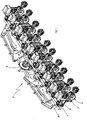
- the reference 1 indicates as a whole a seed distribution element intended for equipping a sowing element 2 of a precision pneumatic seed drill 3.
- the distribution element 1 is the device intended to deposit one seed 4 at a time at a predetermined adjustable spacing in a sowing furrow opened by a coulter 5.
- the sowing element 2, besides the distribution element 1, comprises a frame 6 and a seed store or hopper 7, besides other devices which are known per se and not necessary for the understanding of the present invention.
- the seed drill 3 itself comprises a bearing structure 8 on which a plurality of sowing elements 2 are mounted, all connected to a pneumatic suction device 9.
- the sowing element 1 itself comprises a housing 10 with a fixed portion 11 fixed in a stable manner on the frame 6 and a movable portion 12 hinged in the region of a hinge 12a on the fixed portion 11 by means of a removable hinge pin 13.
- the fixed portion includes a throat 14 by means of which it is connected below an outflow mouth of the store or hopper 7 in such a way as to be fed directly by the latter.
- the seed flows through a gate 14a through which the seed flows into a seed collection chamber 15.
- a sowing disc 16 separates the seed collection chamber 15 from a suction chamber 17 provided in the movable portion 12.
- a suction device 18 mounted on the bearing structure 8 is connected to the suction chamber 17 by means of pipes 19 for producing a pressure differential between the opposed surfaces 16a, 16b of the selector disc 16.
- the sowing disc 16 is removably mounted on a motor-driven drive shaft 20, supported in the fixed portion 11 and driven in rotation at predetermined adjustable speeds by a transmission which is not shown.
- the presence of the transmission requires the shaft 20 to be mounted on the fixed portion 11 of the housing 10.
- the keying between the shaft 20 and the disc 16 is obtained by means of a polygonal profile 21 at the free end of the shaft 20 which protrudes beyond the disc 16 and preferably has chamfers 22 which serve to facilitate the functions explained hereinafter.
- At the periphery of the disc 16 is/are provided one (or several) ring(s) of holes 23 passing between the opposed faces of the sowing disc 16.
- a seal 24 is fitted in the suction chamber 17 and is placed in sliding contact with the facing surface of the disc 16, when the movable portion 11 is closed on the fixed portion 12, to delimit a circumferential segment in which the holes 23 are subjected to the aforesaid pressure differential.
- the circumferential segment extends between the seed collection chamber 15 and a seed fall pipe 25 in which the seeds are released one at a time into the furrow formed by the coulter 5.
- a thrust-bearing element indicated as a whole by 26 is mounted on the movable portion.
- the thrust-bearing element 26 comprises a shaft 27 rotatably mounted by means of bearings 28 in a seat 29 of the movable portion 12.
- the shaft 27 has flanging 30 by means of which it is fixed to a thrust-bearing plate 31 which can bear on that surface of the disc which faces the seal 24 in a zone radially inside the ring of holes 23 in order to withstand at least some of the axial load produced by the disc 16 on the seal 24.
- the bearing between the thrust-bearing plate 31 and the disc 16 takes place in the region of a ring 31a in relief on the surface of the plate which faces the disc 16.
- the thrust-bearing element 26 is driven in rotation with the sowing disc 16 when the fixed and movable portions 11, 12 are closed against one another by means of a drive element 32 which comprises a coupling device constrained for rotation with the thrust-bearing plate but with radial and/or circumferential clearance in such a way as to be self-centred in the rotational coupling with the drive shaft of the disc 16.
- the drive element 32 is coupled with limited radial and/or circumferential clearance to the element 26 by means of one (or more) appendage(s) 33 protruding radially towards the outside and fitted into corresponding seats 34 of the plate.
- the drive element 32 is coupled by means of an internal polygonal profile 35 (similar to that adopted for box-end wrenches) to the polygonal profile 21 of the free end of the shaft 20, the chamfers 22 of which serve to facilitate the centring of the two profiles and the respective engagement.
- the drive element 32 is thus self-centring relative to the drive shaft 20 by which it is driven.
- the positioning between seal 24 and plate 31 is such that the rotation of the latter will not be hindered by the presence of the seal 24 and, at the same time, both will be kept bearing against the disc 16.
- the whole of the movable portion 12 complete with thrust-bearing element 26 and seal 24 lends itself advantageously to the production of a kit for the retrofitting of existing seed drills. It is sufficient in this case to separate the old type of movable portion by removing the hinge pin 13 and replacing the old movable portion with the aforesaid kit. By reconnecting the pneumatic pipes previously disconnected, the seed drill becomes ready for use.
- the distribution element according to the invention is the fact that the wear on the seal resulting from the sliding contact with the seed selector disc is substantially reduced, if not eliminated; the thrust-bearing element is self-centring, thereby allowing easy opening and closing of the movable portion on the fixed portion of the housing; the system additionally lends itself to easy retrofitting, all without removing movable parts and/or operations of disconnecting the sowing disc.
Landscapes
- Life Sciences & Earth Sciences (AREA)
- Soil Sciences (AREA)
- Environmental Sciences (AREA)
- Sowing (AREA)
- Perforating, Stamping-Out Or Severing By Means Other Than Cutting (AREA)
- Drilling Tools (AREA)
- Drilling And Boring (AREA)
Claims (10)
- Saatausbringungselement (1) für Präzisions-Pneumatik-Drillmaschinen (3), des Typs, enthaltend:- eine Säscheibe (16), welche von einer Motor-angetriebenen Übertragungswelle (20) mit kontrollierter Geschwindigkeit gedreht wird,- ein Gehäuse (10) mit einem festen Teil (11) in dem die Welle (20) gelagert ist und einem Teil (12), welcher relativ zu dem festen Teil (11) beweglich ist und gegen ihn geschlossen werden kann,- eine Saatsammelkammer (15), die in dem festen Teil (11) definiert ist,- eine Pneumatik-Saugkammer (17), die in dem beweglichen Teil (12) definiert ist,- wobei die Säscheibe (16) zwischen den Teilen (11, 12) angeordnet ist und entgegengesetzte Oberflächen aufweist, die die Kammern (15, 17) begrenzen,- wobei die Säscheibe (16) zumindest einen Ring von Auswahllöchern (23) aufweist, die sich zwischen den entgegengesetzten Oberflächen erstrecken, und- eine Dichtung (24), welche auf dem beweglichen Teil (12) angeordnet ist und fähig ist zum gleitenden Kontakt mit der zugewandten Oberfläche der Scheibe (16), wenn die Teile (11, 12) gegeneinander geschlossen sind,wobei das Saatausbringungselement (1) des Weiteren eine Saugvorrichtung zum Erzeugen eines Druckdifferenzials zwischen den entgegengesetzten Oberflächen im Bereich eines Umfangssegments des Rings von Löchern (23) umfasst, dadurch gekennzeichnet, dass das Saatausbringungselement (1) des Weiteren ein Drucklagerelement (26) der Säscheibe (16) umfasst, wobei das Drucklagerelement (26) in dem beweglichen Teil (12) drehbar gelagert ist, um zumindest etwas der durch die Scheibe (16) auf die Dichtung (24) erzeugten axialen Last zu widerstehen, wobei das Drucklagerelement (26) an dem bewegliche Teil angebracht ist, um den Verschleiß der Dichtung (24) zu begrenzen, der aus dem durch Gleiten gegen die Oberfläche der Scheibe (16) resultiert und wobei das Drucklagerelement (26) eine Welle (27) umfasst, die mit Hilfe von Lagern (28) in einem Sitz (29) des beweglichen Teils (12) drehbar gelagert ist, wobei die Welle (27) eine Flansch (30) aufweist, mit der sie an einer Drucklagerplatte (31) befestigt ist, die auf der der Dichtung (24) zugewandten Seite der Scheibe in einer Zone radial innerhalb des Lochrings (23) aufliegen kann, um zumindest einem Teil der von der Scheibe (16) auf die Dichtung (24) ausgeübten axialen Last zu widerstehen.
- Saatausbringungselement (1) nach Anspruch 1, wobei das Drucklagerelement (26) mit der Scheibe (16) gedreht wird, wenn die Teile (11, 12) gegeneinander geschlossen sind.
- Saatausbringungselement (1) nach Anspruch 1, wobei das Drucklagerelement (26) ein Antriebselement (32) umfasst, welches zur Drehung mit der Platte (31) fixiert ist und mit der Antriebswelle (20) der Scheibe (16) gekoppelt werden kann, wenn die Teile (11, 12) gegeneinander geschlossen sind.
- Saatausbringungselement (1) nach Anspruch 3, wobei das Antriebselement (32) selbst-zentrierend relativ zur Antriebswelle (20) ist.
- Saatausbringungselement (1) nach Anspruch 3 oder Anspruch 4, wobei das Antriebselement (32) ein Kupplungsbauteil (33) umfasst, welches sich gemeinsam mit der Drucklagerplatte (31) dreht, aber einen radialen und/oder umlaufenden Freiraum aufweist, um selbst-zentrierend während drehender Kupplung mit der Antriebswelle (20) der Scheibe (16) zu sein.
- Saatausbringungselement (1) nach einem oder mehreren der vorhergehenden Ansprüche, wobei der bewegliche Teil (12) an dem festen Teil (11) gelenkig angebracht ist.
- Säelement für Präzisionsdrillmaschinen (3), enthaltend einen Rahmen (6), auf welchem ein Saatausbringungselement (1) nach einem oder mehreren der vorhergehenden Ansprüche montiert ist.
- Drillmaschine (3), umfassend eine Stützstruktur, auf welcher eine Mehrzahl von Säelementen nach Anspruch 8 montiert ist.
- Set zum Umrüsten von Saatausbringungselementen (1) von Präzisions-Pneumatik-Drillmaschinen (3), wobei die Ausbringungselemente (1) vom Typ sind, der enthält:- eine Säscheibe (16), welche von einer Motor-angetriebenen Übertragungswelle (20) mit kontrollierter Geschwindigkeit gedreht wird,- ein Gehäuse (10) mit einem festen Teil (11), in welchem die Welle gelagert ist, und einem Teil (12), welcher relativ zu dem festen Teil (11) beweglich ist und gegen ihn geschlossen werden kann,- eine Saatsammelkammer (15), die in dem festen Teil (11) definiert ist,- eine Pneumatik-Saugkammer (17), die in dem beweglichen Teil (12) definiert ist,- wobei die Säscheibe (16) zwischen den Teilen (11, 12) angeordnet ist und entgegengesetzte Oberflächen aufweist, die die Kammern (15, 17) begrenzen,- wobei die Säscheibe (16) zumindest einen Ring von Auswahllöchern (23) aufweist, die sich zwischen den entgegengesetzten Oberflächen erstrecken, und- eine Dichtung (24), welche auf dem beweglichen Teil (12) angeordnet ist und fähig ist zum gleitenden Kontakt mit der zugewandten Oberfläche der Scheibe (16), wenn die Teile (11, 12) gegeneinander geschlossen sind,wobei ein Druckdifferenzial zwischen den entgegengesetzten Oberflächen im Bereich eines Umfangselements des Rings von Löchern (23) bereitgestellt wird, dadurch gekennzeichnet, dass das Set umfasst:- den beweglichen Teil (12) vormontiert mit:- einem Drucklagerelement (26) der Säscheibe (16), wobei das Drucklagerelement (26) in den beweglichen Teil (12) drehbar gelagert ist, um zumindest etwas der durch die Scheibe (16) auf die Dichtung (24) erzeugten axialen Last zu widerstehen, wobei das Drucklagerelement (26) an dem bewegliche Teil angebracht ist, um den Verschleiß der Dichtung (24) zu begrenzen, der aus dem durch Gleiten gegen die Oberfläche der Scheibe (16) resultiert und wobei das Drucklagerelement (26) eine Welle (27) umfasst, die mit Hilfe von Lagern (28) in einem Sitz (29) des beweglichen Teils (12) drehbar gelagert ist, wobei die Welle (27) eine Flansch (30) aufweist, mit der sie an einer Drucklagerplatte (31) befestigt ist, die auf der der Dichtung (24) zugewandten Seite der Scheibe in einer Zone radial innerhalb des Lochrings (23) aufliegen kann, um zumindest einem Teil der von der Scheibe (16) auf die Dichtung (24) ausgeübten axialen Last zu widerstehen.
- Set nach Anspruch 9, wobei der bewegliche Teil (12) und das Drucklagerelement (26) eines oder mehrere der Merkmale der Ansprüche 2 bis 6 umfassen.
Applications Claiming Priority (3)
| Application Number | Priority Date | Filing Date | Title |
|---|---|---|---|
| ITPD2010A000338A IT1402950B1 (it) | 2010-11-12 | 2010-11-12 | Elemento distributore del seme per seminatrici di precisione, seminatrice includente detto elemento |
| PCT/EP2011/069875 WO2012062876A1 (en) | 2010-11-12 | 2011-11-10 | Seed distribution element for precision seed drills, seed drill including said element |
| EP11779702.7A EP2637492B2 (de) | 2010-11-12 | 2011-11-10 | Samenverteilungselement für präzionssämaschine und sämaschine mit diesem element |
Related Parent Applications (2)
| Application Number | Title | Priority Date | Filing Date |
|---|---|---|---|
| EP11779702.7A Division-Into EP2637492B2 (de) | 2010-11-12 | 2011-11-10 | Samenverteilungselement für präzionssämaschine und sämaschine mit diesem element |
| EP11779702.7A Division EP2637492B2 (de) | 2010-11-12 | 2011-11-10 | Samenverteilungselement für präzionssämaschine und sämaschine mit diesem element |
Publications (3)
| Publication Number | Publication Date |
|---|---|
| EP2848109A1 EP2848109A1 (de) | 2015-03-18 |
| EP2848109B1 EP2848109B1 (de) | 2016-11-09 |
| EP2848109B2 true EP2848109B2 (de) | 2022-08-10 |
Family
ID=43742897
Family Applications (2)
| Application Number | Title | Priority Date | Filing Date |
|---|---|---|---|
| EP14187190.5A Active EP2848109B2 (de) | 2010-11-12 | 2011-11-10 | Samenverteilungselement für Präzisionsdrillmaschinen, Drillmaschine mit besagtem Element |
| EP11779702.7A Active EP2637492B2 (de) | 2010-11-12 | 2011-11-10 | Samenverteilungselement für präzionssämaschine und sämaschine mit diesem element |
Family Applications After (1)
| Application Number | Title | Priority Date | Filing Date |
|---|---|---|---|
| EP11779702.7A Active EP2637492B2 (de) | 2010-11-12 | 2011-11-10 | Samenverteilungselement für präzionssämaschine und sämaschine mit diesem element |
Country Status (5)
| Country | Link |
|---|---|
| US (1) | US8770121B2 (de) |
| EP (2) | EP2848109B2 (de) |
| CN (1) | CN102740678B (de) |
| IT (1) | IT1402950B1 (de) |
| WO (1) | WO2012062876A1 (de) |
Families Citing this family (28)
| Publication number | Priority date | Publication date | Assignee | Title |
|---|---|---|---|---|
| IT1402950B1 (it) | 2010-11-12 | 2013-09-27 | Maschio Gaspardo Spa | Elemento distributore del seme per seminatrici di precisione, seminatrice includente detto elemento |
| ES2632418T3 (es) * | 2011-03-22 | 2017-09-13 | Precision Planting Llc | Medidor de semillas |
| CN103843499B (zh) * | 2012-12-03 | 2016-03-16 | 河北农业大学 | 一种圆盘气吸式排种装置 |
| AR099073A1 (es) * | 2014-01-09 | 2016-06-29 | Kinze Mfg Inc | Disco de semillas con transmisión integrada |
| MX391150B (es) * | 2014-04-17 | 2025-03-21 | Maschio Gaspardo Spa | Elemento de siembra para sembradoras neumaticas de precision. |
| AR098148A1 (es) * | 2014-05-22 | 2016-05-04 | Alberto Gentili Jorge | Dispositivo distribuidor de semillas por accionamiento directo |
| CN104115595B (zh) * | 2014-06-11 | 2016-07-06 | 史丹希中国有限公司 | 真空吸附式精量播种器 |
| CN105165188B (zh) * | 2015-10-09 | 2017-04-05 | 甘肃武威兴旺农机制造有限公司 | 一种手推气吸式精量点播机 |
| ITUB20155280A1 (it) * | 2015-10-19 | 2017-04-19 | Matermacc S P A | Dispositivo distributore di materiale per macchine agricole. |
| CN105165189B (zh) * | 2015-10-29 | 2017-03-08 | 东北农业大学 | 气吸式电动排种盘 |
| US10555455B2 (en) * | 2017-08-07 | 2020-02-11 | Deere & Company | Work vehicle with commodity metering system and airflow system |
| WO2019092538A1 (en) | 2017-11-10 | 2019-05-16 | Maschio Gaspardo S.P.A. | Sowing element for precision agricultural seeders and seeder including element of this kind |
| EP3706536B1 (de) * | 2017-11-10 | 2022-08-17 | Maschio Gaspardo S.p.A. | Säeinheit für landwirtschaftliche präzisionssämaschine und sämaschine mit einer säeinheit dieser art |
| ES2906214T3 (es) * | 2017-11-10 | 2022-04-13 | Maschio Gaspardo Spa | Elemento sembrador para sembradoras agrícolas de precisión y sembradora que comprende el elemento sembrador |
| CN109566016A (zh) * | 2019-02-01 | 2019-04-05 | 东北林业大学 | 一种气吸式平贝母播种机的卸种包胶轮装置 |
| US11582899B2 (en) | 2019-12-24 | 2023-02-21 | Cnh Industrial America Llc | Particle delivery system of an agricultural row unit |
| US11523555B2 (en) | 2019-12-24 | 2022-12-13 | Cnh Industrial America Llc | Particle delivery system of an agricultural row unit |
| US11483963B2 (en) | 2019-12-24 | 2022-11-01 | Cnh Industrial America Llc | Particle delivery system of an agricultural row unit |
| US11564344B2 (en) | 2019-12-24 | 2023-01-31 | Cnh Industrial America Llc | Particle delivery system of an agricultural row unit |
| US11523556B2 (en) | 2019-12-24 | 2022-12-13 | Cnh Industrial America Llc | Particle delivery system of an agricultural row unit |
| US11490558B2 (en) | 2019-12-24 | 2022-11-08 | Cnh Industrial America Llc | Particle delivery system of an agricultural row unit |
| US11589500B2 (en) | 2019-12-24 | 2023-02-28 | Cnh Industrial America Llc | Particle delivery system of an agricultural row unit |
| US11553639B2 (en) | 2019-12-24 | 2023-01-17 | Cnh Industrial America Llc | Particle delivery system of an agricultural row unit |
| US11516958B2 (en) | 2019-12-24 | 2022-12-06 | Cnh Industrial America Llc | Particle delivery system of an agricultural row unit |
| US11596095B2 (en) | 2019-12-24 | 2023-03-07 | Cnh Industrial America Llc | Particle delivery system of an agricultural row unit |
| US11553638B2 (en) | 2019-12-24 | 2023-01-17 | Cnh Industrial America Llc | Particle delivery system of an agricultural row unit |
| US11564346B2 (en) | 2019-12-24 | 2023-01-31 | Cnh Industrial America Llc | Particle delivery system of an agricultural row unit |
| CN119183742B (zh) * | 2024-11-13 | 2025-02-21 | 扬州大学 | 一种播种间距可调的播种机 |
Citations (6)
| Publication number | Priority date | Publication date | Assignee | Title |
|---|---|---|---|---|
| EP0140699A2 (de) † | 1983-10-31 | 1985-05-08 | Deere & Company | Montagevorrichtung für eine Säscheibe |
| US4664290A (en) † | 1985-02-25 | 1987-05-12 | Deere & Company | Method and apparatus for precise positioning of a seed disk in a seed meter |
| EP0636305A1 (de) † | 1993-07-29 | 1995-02-01 | MATERMACC s.r.l. | Einzelkornsämaschine |
| DE68916976T2 (de) † | 1988-04-22 | 1995-03-16 | Ribouleau Ateliers | Verteiler für eine Einzelkörnersämaschine. |
| WO1996002123A1 (en) † | 1994-07-14 | 1996-02-01 | Stanhay Webb Limited | Seed dispensing mechanisms |
| WO2012062879A1 (en) † | 2010-11-10 | 2012-05-18 | Zimmer Spine | Bone anchor |
Family Cites Families (8)
| Publication number | Priority date | Publication date | Assignee | Title |
|---|---|---|---|---|
| ES2013539A6 (es) | 1989-06-09 | 1990-05-01 | Concejo Sainz Pedro Antonio | Dosificador de semillas para maquinas sembradoras. |
| IT1253373B (it) * | 1991-10-07 | 1995-08-08 | Matermacc | Seminatrice pneumatica di precisione perfezionata. |
| US6247418B1 (en) | 1998-04-15 | 2001-06-19 | Case Corporation | Seed metering system with improved wear enhancement |
| BR9903060A (pt) * | 1999-04-23 | 2001-03-20 | Justino De Moraes Irmaos S A | Distribuidor de sementes de hortaliças e legumes para um implemento agrìcola semeador |
| US6932236B2 (en) | 2002-03-28 | 2005-08-23 | Dale A. Ven Huizen | Method and apparatus for improving the efficiency of a John Deere vacuum planter |
| US7228807B1 (en) * | 2006-03-29 | 2007-06-12 | Venhuizen Dale | Device for improving the spacing between seeds planted by a John Deere vacuum planter |
| CN200956724Y (zh) * | 2006-10-13 | 2007-10-10 | 华中农业大学 | 光电检测的气流式油菜精量排种器 |
| IT1402950B1 (it) | 2010-11-12 | 2013-09-27 | Maschio Gaspardo Spa | Elemento distributore del seme per seminatrici di precisione, seminatrice includente detto elemento |
-
2010
- 2010-11-12 IT ITPD2010A000338A patent/IT1402950B1/it active
-
2011
- 2011-11-10 US US13/521,896 patent/US8770121B2/en active Active
- 2011-11-10 EP EP14187190.5A patent/EP2848109B2/de active Active
- 2011-11-10 EP EP11779702.7A patent/EP2637492B2/de active Active
- 2011-11-10 WO PCT/EP2011/069875 patent/WO2012062876A1/en not_active Ceased
- 2011-11-10 CN CN201180007000.9A patent/CN102740678B/zh active Active
Patent Citations (6)
| Publication number | Priority date | Publication date | Assignee | Title |
|---|---|---|---|---|
| EP0140699A2 (de) † | 1983-10-31 | 1985-05-08 | Deere & Company | Montagevorrichtung für eine Säscheibe |
| US4664290A (en) † | 1985-02-25 | 1987-05-12 | Deere & Company | Method and apparatus for precise positioning of a seed disk in a seed meter |
| DE68916976T2 (de) † | 1988-04-22 | 1995-03-16 | Ribouleau Ateliers | Verteiler für eine Einzelkörnersämaschine. |
| EP0636305A1 (de) † | 1993-07-29 | 1995-02-01 | MATERMACC s.r.l. | Einzelkornsämaschine |
| WO1996002123A1 (en) † | 1994-07-14 | 1996-02-01 | Stanhay Webb Limited | Seed dispensing mechanisms |
| WO2012062879A1 (en) † | 2010-11-10 | 2012-05-18 | Zimmer Spine | Bone anchor |
Non-Patent Citations (1)
| Title |
|---|
| AMAZONEN-WERKE H. DREYER GMBH & CO.KG: "Einzelkorn-Sämaschine ED 302, ED 452, ED 452-K, ED 602-K, ED 902-K", BETRIEBSANLEITUNG, October 2005 (2005-10-01), pages 1 - 170 † |
Also Published As
| Publication number | Publication date |
|---|---|
| EP2637492B1 (de) | 2014-12-03 |
| RU2012136948A (ru) | 2014-03-10 |
| EP2848109B1 (de) | 2016-11-09 |
| CN102740678A (zh) | 2012-10-17 |
| US8770121B2 (en) | 2014-07-08 |
| ITPD20100338A1 (it) | 2012-05-13 |
| EP2637492A1 (de) | 2013-09-18 |
| US20130019788A1 (en) | 2013-01-24 |
| WO2012062876A8 (en) | 2012-08-23 |
| CN102740678B (zh) | 2016-02-24 |
| EP2637492B2 (de) | 2025-03-26 |
| WO2012062876A1 (en) | 2012-05-18 |
| EP2848109A1 (de) | 2015-03-18 |
| IT1402950B1 (it) | 2013-09-27 |
Similar Documents
| Publication | Publication Date | Title |
|---|---|---|
| EP2848109B1 (de) | Samenverteilungselement für Präzisionsdrillmaschinen, Drillmaschine mit besagtem Element | |
| EP2225928B1 (de) | Säscheibe, Staatgutmessgerät und Sämaschine | |
| US4469230A (en) | Sorting cylinder for seeds and other grains | |
| JP6353067B2 (ja) | タレットを備える回転式タブレットプレス機及び回転式タブレットプレス機の部品の改良された調整を提供する方法 | |
| CA2272504C (en) | Segmented meter roller assembly | |
| CN105052319A (zh) | 油麦兼用型集排式种子定量器 | |
| US6361302B1 (en) | Rotary tabletting machine | |
| CN113196916A (zh) | 指夹式取种器、可调式取种装置和可调式穴播器 | |
| CN101161888B (zh) | 用于织机的轴传动装置 | |
| EP1777003B1 (de) | Rillenprofil für das Mahlgehäuse einer Zerkleinerungsmaschine | |
| RU2575027C2 (ru) | Распределитель семян прецизионной рядовой сеялки и рядовая сеялка, содержащая такой распределитель семян | |
| CN111642196B (zh) | 一种滚筒式气力排种装置 | |
| CN116267122B (zh) | 一种便于安装更换滚筒的播种装置 | |
| TW200918802A (en) | Roll stand for rolling metallic strips and roll or cylinder for a roll stand of this type | |
| EP1777004B1 (de) | Selbstkorrigierende Lochplatteneinbaueinrichtung für eine Lochplattte einer Zerkleinerungsmaschine | |
| CN106837883B (zh) | 多级离心泵 | |
| CN212650070U (zh) | 一种气吸式精量排种器 | |
| CN114586509A (zh) | 指夹式取种器、指夹式播种盘和指夹式播种装置 | |
| CN2919821Y (zh) | 可拆卸式播种轮轮轴装置 | |
| CN119769255B (zh) | 一种复合排种器 | |
| CN220258112U (zh) | 用于砂辊米机的无轴砂轮组传动机构及砂辊米机 | |
| CN101015780A (zh) | 滴丸去油机 | |
| US20240410237A1 (en) | Wrench assembly bumper plate systems | |
| CN207913895U (zh) | 带传动式行星多筒研磨机 | |
| US729953A (en) | Refining-engine for paper-pulp. |
Legal Events
| Date | Code | Title | Description |
|---|---|---|---|
| PUAI | Public reference made under article 153(3) epc to a published international application that has entered the european phase |
Free format text: ORIGINAL CODE: 0009012 |
|
| 17P | Request for examination filed |
Effective date: 20140930 |
|
| AC | Divisional application: reference to earlier application |
Ref document number: 2637492 Country of ref document: EP Kind code of ref document: P |
|
| AK | Designated contracting states |
Kind code of ref document: A1 Designated state(s): AL AT BE BG CH CY CZ DE DK EE ES FI FR GB GR HR HU IE IS IT LI LT LU LV MC MK MT NL NO PL PT RO RS SE SI SK SM TR |
|
| R17P | Request for examination filed (corrected) |
Effective date: 20150918 |
|
| RBV | Designated contracting states (corrected) |
Designated state(s): AL AT BE BG CH CY CZ DE DK EE ES FI FR GB GR HR HU IE IS IT LI LT LU LV MC MK MT NL NO PL PT RO RS SE SI SK SM TR |
|
| GRAP | Despatch of communication of intention to grant a patent |
Free format text: ORIGINAL CODE: EPIDOSNIGR1 |
|
| INTG | Intention to grant announced |
Effective date: 20160601 |
|
| GRAS | Grant fee paid |
Free format text: ORIGINAL CODE: EPIDOSNIGR3 |
|
| GRAA | (expected) grant |
Free format text: ORIGINAL CODE: 0009210 |
|
| AC | Divisional application: reference to earlier application |
Ref document number: 2637492 Country of ref document: EP Kind code of ref document: P |
|
| AK | Designated contracting states |
Kind code of ref document: B1 Designated state(s): AL AT BE BG CH CY CZ DE DK EE ES FI FR GB GR HR HU IE IS IT LI LT LU LV MC MK MT NL NO PL PT RO RS SE SI SK SM TR |
|
| REG | Reference to a national code |
Ref country code: GB Ref legal event code: FG4D |
|
| REG | Reference to a national code |
Ref country code: AT Ref legal event code: REF Ref document number: 842999 Country of ref document: AT Kind code of ref document: T Effective date: 20161115 Ref country code: CH Ref legal event code: EP |
|
| REG | Reference to a national code |
Ref country code: IE Ref legal event code: FG4D |
|
| REG | Reference to a national code |
Ref country code: FR Ref legal event code: PLFP Year of fee payment: 6 |
|
| REG | Reference to a national code |
Ref country code: DE Ref legal event code: R096 Ref document number: 602011032345 Country of ref document: DE |
|
| PG25 | Lapsed in a contracting state [announced via postgrant information from national office to epo] |
Ref country code: LV Free format text: LAPSE BECAUSE OF FAILURE TO SUBMIT A TRANSLATION OF THE DESCRIPTION OR TO PAY THE FEE WITHIN THE PRESCRIBED TIME-LIMIT Effective date: 20161109 |
|
| REG | Reference to a national code |
Ref country code: LT Ref legal event code: MG4D |
|
| REG | Reference to a national code |
Ref country code: NL Ref legal event code: MP Effective date: 20161109 |
|
| REG | Reference to a national code |
Ref country code: AT Ref legal event code: MK05 Ref document number: 842999 Country of ref document: AT Kind code of ref document: T Effective date: 20161109 |
|
| PG25 | Lapsed in a contracting state [announced via postgrant information from national office to epo] |
Ref country code: GR Free format text: LAPSE BECAUSE OF FAILURE TO SUBMIT A TRANSLATION OF THE DESCRIPTION OR TO PAY THE FEE WITHIN THE PRESCRIBED TIME-LIMIT Effective date: 20170210 Ref country code: NO Free format text: LAPSE BECAUSE OF FAILURE TO SUBMIT A TRANSLATION OF THE DESCRIPTION OR TO PAY THE FEE WITHIN THE PRESCRIBED TIME-LIMIT Effective date: 20170209 Ref country code: LT Free format text: LAPSE BECAUSE OF FAILURE TO SUBMIT A TRANSLATION OF THE DESCRIPTION OR TO PAY THE FEE WITHIN THE PRESCRIBED TIME-LIMIT Effective date: 20161109 Ref country code: NL Free format text: LAPSE BECAUSE OF FAILURE TO SUBMIT A TRANSLATION OF THE DESCRIPTION OR TO PAY THE FEE WITHIN THE PRESCRIBED TIME-LIMIT Effective date: 20161109 Ref country code: SE Free format text: LAPSE BECAUSE OF FAILURE TO SUBMIT A TRANSLATION OF THE DESCRIPTION OR TO PAY THE FEE WITHIN THE PRESCRIBED TIME-LIMIT Effective date: 20161109 |
|
| PG25 | Lapsed in a contracting state [announced via postgrant information from national office to epo] |
Ref country code: ES Free format text: LAPSE BECAUSE OF FAILURE TO SUBMIT A TRANSLATION OF THE DESCRIPTION OR TO PAY THE FEE WITHIN THE PRESCRIBED TIME-LIMIT Effective date: 20161109 Ref country code: BE Free format text: LAPSE BECAUSE OF NON-PAYMENT OF DUE FEES Effective date: 20161130 Ref country code: FI Free format text: LAPSE BECAUSE OF FAILURE TO SUBMIT A TRANSLATION OF THE DESCRIPTION OR TO PAY THE FEE WITHIN THE PRESCRIBED TIME-LIMIT Effective date: 20161109 Ref country code: IS Free format text: LAPSE BECAUSE OF FAILURE TO SUBMIT A TRANSLATION OF THE DESCRIPTION OR TO PAY THE FEE WITHIN THE PRESCRIBED TIME-LIMIT Effective date: 20170309 Ref country code: RS Free format text: LAPSE BECAUSE OF FAILURE TO SUBMIT A TRANSLATION OF THE DESCRIPTION OR TO PAY THE FEE WITHIN THE PRESCRIBED TIME-LIMIT Effective date: 20161109 Ref country code: HR Free format text: LAPSE BECAUSE OF FAILURE TO SUBMIT A TRANSLATION OF THE DESCRIPTION OR TO PAY THE FEE WITHIN THE PRESCRIBED TIME-LIMIT Effective date: 20161109 Ref country code: PT Free format text: LAPSE BECAUSE OF FAILURE TO SUBMIT A TRANSLATION OF THE DESCRIPTION OR TO PAY THE FEE WITHIN THE PRESCRIBED TIME-LIMIT Effective date: 20170309 Ref country code: PL Free format text: LAPSE BECAUSE OF FAILURE TO SUBMIT A TRANSLATION OF THE DESCRIPTION OR TO PAY THE FEE WITHIN THE PRESCRIBED TIME-LIMIT Effective date: 20161109 Ref country code: AT Free format text: LAPSE BECAUSE OF FAILURE TO SUBMIT A TRANSLATION OF THE DESCRIPTION OR TO PAY THE FEE WITHIN THE PRESCRIBED TIME-LIMIT Effective date: 20161109 |
|
| REG | Reference to a national code |
Ref country code: CH Ref legal event code: PL |
|
| PG25 | Lapsed in a contracting state [announced via postgrant information from national office to epo] |
Ref country code: RO Free format text: LAPSE BECAUSE OF FAILURE TO SUBMIT A TRANSLATION OF THE DESCRIPTION OR TO PAY THE FEE WITHIN THE PRESCRIBED TIME-LIMIT Effective date: 20161109 Ref country code: CZ Free format text: LAPSE BECAUSE OF FAILURE TO SUBMIT A TRANSLATION OF THE DESCRIPTION OR TO PAY THE FEE WITHIN THE PRESCRIBED TIME-LIMIT Effective date: 20161109 Ref country code: LI Free format text: LAPSE BECAUSE OF NON-PAYMENT OF DUE FEES Effective date: 20161130 Ref country code: SK Free format text: LAPSE BECAUSE OF FAILURE TO SUBMIT A TRANSLATION OF THE DESCRIPTION OR TO PAY THE FEE WITHIN THE PRESCRIBED TIME-LIMIT Effective date: 20161109 Ref country code: EE Free format text: LAPSE BECAUSE OF FAILURE TO SUBMIT A TRANSLATION OF THE DESCRIPTION OR TO PAY THE FEE WITHIN THE PRESCRIBED TIME-LIMIT Effective date: 20161109 Ref country code: CH Free format text: LAPSE BECAUSE OF NON-PAYMENT OF DUE FEES Effective date: 20161130 Ref country code: DK Free format text: LAPSE BECAUSE OF FAILURE TO SUBMIT A TRANSLATION OF THE DESCRIPTION OR TO PAY THE FEE WITHIN THE PRESCRIBED TIME-LIMIT Effective date: 20161109 |
|
| REG | Reference to a national code |
Ref country code: DE Ref legal event code: R026 Ref document number: 602011032345 Country of ref document: DE |
|
| PLBI | Opposition filed |
Free format text: ORIGINAL CODE: 0009260 |
|
| REG | Reference to a national code |
Ref country code: IE Ref legal event code: MM4A |
|
| PG25 | Lapsed in a contracting state [announced via postgrant information from national office to epo] |
Ref country code: BG Free format text: LAPSE BECAUSE OF FAILURE TO SUBMIT A TRANSLATION OF THE DESCRIPTION OR TO PAY THE FEE WITHIN THE PRESCRIBED TIME-LIMIT Effective date: 20170209 Ref country code: SM Free format text: LAPSE BECAUSE OF FAILURE TO SUBMIT A TRANSLATION OF THE DESCRIPTION OR TO PAY THE FEE WITHIN THE PRESCRIBED TIME-LIMIT Effective date: 20161109 Ref country code: BE Free format text: LAPSE BECAUSE OF FAILURE TO SUBMIT A TRANSLATION OF THE DESCRIPTION OR TO PAY THE FEE WITHIN THE PRESCRIBED TIME-LIMIT Effective date: 20161109 |
|
| 26 | Opposition filed |
Opponent name: PRECISION PLANTING LLC Effective date: 20170808 |
|
| PLAX | Notice of opposition and request to file observation + time limit sent |
Free format text: ORIGINAL CODE: EPIDOSNOBS2 |
|
| PG25 | Lapsed in a contracting state [announced via postgrant information from national office to epo] |
Ref country code: LU Free format text: LAPSE BECAUSE OF NON-PAYMENT OF DUE FEES Effective date: 20161130 Ref country code: MC Free format text: LAPSE BECAUSE OF FAILURE TO SUBMIT A TRANSLATION OF THE DESCRIPTION OR TO PAY THE FEE WITHIN THE PRESCRIBED TIME-LIMIT Effective date: 20161109 |
|
| GBPC | Gb: european patent ceased through non-payment of renewal fee |
Effective date: 20170209 |
|
| REG | Reference to a national code |
Ref country code: FR Ref legal event code: PLFP Year of fee payment: 7 |
|
| PG25 | Lapsed in a contracting state [announced via postgrant information from national office to epo] |
Ref country code: IE Free format text: LAPSE BECAUSE OF NON-PAYMENT OF DUE FEES Effective date: 20161110 Ref country code: SI Free format text: LAPSE BECAUSE OF FAILURE TO SUBMIT A TRANSLATION OF THE DESCRIPTION OR TO PAY THE FEE WITHIN THE PRESCRIBED TIME-LIMIT Effective date: 20161109 |
|
| PLBB | Reply of patent proprietor to notice(s) of opposition received |
Free format text: ORIGINAL CODE: EPIDOSNOBS3 |
|
| PG25 | Lapsed in a contracting state [announced via postgrant information from national office to epo] |
Ref country code: GB Free format text: LAPSE BECAUSE OF NON-PAYMENT OF DUE FEES Effective date: 20170209 |
|
| PG25 | Lapsed in a contracting state [announced via postgrant information from national office to epo] |
Ref country code: HU Free format text: LAPSE BECAUSE OF FAILURE TO SUBMIT A TRANSLATION OF THE DESCRIPTION OR TO PAY THE FEE WITHIN THE PRESCRIBED TIME-LIMIT; INVALID AB INITIO Effective date: 20111110 |
|
| PG25 | Lapsed in a contracting state [announced via postgrant information from national office to epo] |
Ref country code: MK Free format text: LAPSE BECAUSE OF FAILURE TO SUBMIT A TRANSLATION OF THE DESCRIPTION OR TO PAY THE FEE WITHIN THE PRESCRIBED TIME-LIMIT Effective date: 20161109 Ref country code: CY Free format text: LAPSE BECAUSE OF FAILURE TO SUBMIT A TRANSLATION OF THE DESCRIPTION OR TO PAY THE FEE WITHIN THE PRESCRIBED TIME-LIMIT Effective date: 20161109 |
|
| PG25 | Lapsed in a contracting state [announced via postgrant information from national office to epo] |
Ref country code: MT Free format text: LAPSE BECAUSE OF NON-PAYMENT OF DUE FEES Effective date: 20161110 |
|
| APBM | Appeal reference recorded |
Free format text: ORIGINAL CODE: EPIDOSNREFNO |
|
| APBP | Date of receipt of notice of appeal recorded |
Free format text: ORIGINAL CODE: EPIDOSNNOA2O |
|
| APAH | Appeal reference modified |
Free format text: ORIGINAL CODE: EPIDOSCREFNO |
|
| APBQ | Date of receipt of statement of grounds of appeal recorded |
Free format text: ORIGINAL CODE: EPIDOSNNOA3O |
|
| PG25 | Lapsed in a contracting state [announced via postgrant information from national office to epo] |
Ref country code: AL Free format text: LAPSE BECAUSE OF FAILURE TO SUBMIT A TRANSLATION OF THE DESCRIPTION OR TO PAY THE FEE WITHIN THE PRESCRIBED TIME-LIMIT Effective date: 20161109 |
|
| APBU | Appeal procedure closed |
Free format text: ORIGINAL CODE: EPIDOSNNOA9O |
|
| PUAH | Patent maintained in amended form |
Free format text: ORIGINAL CODE: 0009272 |
|
| STAA | Information on the status of an ep patent application or granted ep patent |
Free format text: STATUS: PATENT MAINTAINED AS AMENDED |
|
| 27A | Patent maintained in amended form |
Effective date: 20220810 |
|
| AK | Designated contracting states |
Kind code of ref document: B2 Designated state(s): AL AT BE BG CH CY CZ DE DK EE ES FI FR GB GR HR HU IE IS IT LI LT LU LV MC MK MT NL NO PL PT RO RS SE SI SK SM TR |
|
| REG | Reference to a national code |
Ref country code: DE Ref legal event code: R102 Ref document number: 602011032345 Country of ref document: DE |
|
| P01 | Opt-out of the competence of the unified patent court (upc) registered |
Effective date: 20230530 |
|
| PGFP | Annual fee paid to national office [announced via postgrant information from national office to epo] |
Ref country code: DE Payment date: 20251119 Year of fee payment: 15 |
|
| PGFP | Annual fee paid to national office [announced via postgrant information from national office to epo] |
Ref country code: IT Payment date: 20251016 Year of fee payment: 15 |
|
| PGFP | Annual fee paid to national office [announced via postgrant information from national office to epo] |
Ref country code: FR Payment date: 20251125 Year of fee payment: 15 |
|
| PGFP | Annual fee paid to national office [announced via postgrant information from national office to epo] |
Ref country code: TR Payment date: 20251104 Year of fee payment: 15 |