EP2848237A2 - Drehmomentabstützvorrichtung zur Montage eines mit einem Nabenmotor versehenen Antriebsrades an einem Rollstuhl - Google Patents
Drehmomentabstützvorrichtung zur Montage eines mit einem Nabenmotor versehenen Antriebsrades an einem Rollstuhl Download PDFInfo
- Publication number
- EP2848237A2 EP2848237A2 EP14183092.7A EP14183092A EP2848237A2 EP 2848237 A2 EP2848237 A2 EP 2848237A2 EP 14183092 A EP14183092 A EP 14183092A EP 2848237 A2 EP2848237 A2 EP 2848237A2
- Authority
- EP
- European Patent Office
- Prior art keywords
- wheelchair
- hub motor
- drive wheel
- mounting
- drehmomentabstützvorrichtung
- Prior art date
- Legal status (The legal status is an assumption and is not a legal conclusion. Google has not performed a legal analysis and makes no representation as to the accuracy of the status listed.)
- Granted
Links
- 235000004443 Ricinus communis Nutrition 0.000 description 1
- 240000000528 Ricinus communis Species 0.000 description 1
- 238000006243 chemical reaction Methods 0.000 description 1
- 230000003247 decreasing effect Effects 0.000 description 1
- 238000000034 method Methods 0.000 description 1
- 239000000047 product Substances 0.000 description 1
- 239000013589 supplement Substances 0.000 description 1
Images



Classifications
-
- A—HUMAN NECESSITIES
- A61—MEDICAL OR VETERINARY SCIENCE; HYGIENE
- A61G—TRANSPORT, PERSONAL CONVEYANCES, OR ACCOMMODATION SPECIALLY ADAPTED FOR PATIENTS OR DISABLED PERSONS; OPERATING TABLES OR CHAIRS; CHAIRS FOR DENTISTRY; FUNERAL DEVICES
- A61G5/00—Chairs or personal conveyances specially adapted for patients or disabled persons, e.g. wheelchairs
- A61G5/02—Chairs or personal conveyances specially adapted for patients or disabled persons, e.g. wheelchairs propelled by the patient or disabled person
- A61G5/021—Chairs or personal conveyances specially adapted for patients or disabled persons, e.g. wheelchairs propelled by the patient or disabled person having particular propulsion mechanisms
-
- A—HUMAN NECESSITIES
- A61—MEDICAL OR VETERINARY SCIENCE; HYGIENE
- A61G—TRANSPORT, PERSONAL CONVEYANCES, OR ACCOMMODATION SPECIALLY ADAPTED FOR PATIENTS OR DISABLED PERSONS; OPERATING TABLES OR CHAIRS; CHAIRS FOR DENTISTRY; FUNERAL DEVICES
- A61G5/00—Chairs or personal conveyances specially adapted for patients or disabled persons, e.g. wheelchairs
- A61G5/04—Chairs or personal conveyances specially adapted for patients or disabled persons, e.g. wheelchairs motor-driven
- A61G5/048—Power-assistance activated by pushing on hand rim or on handlebar
-
- A—HUMAN NECESSITIES
- A61—MEDICAL OR VETERINARY SCIENCE; HYGIENE
- A61G—TRANSPORT, PERSONAL CONVEYANCES, OR ACCOMMODATION SPECIALLY ADAPTED FOR PATIENTS OR DISABLED PERSONS; OPERATING TABLES OR CHAIRS; CHAIRS FOR DENTISTRY; FUNERAL DEVICES
- A61G5/00—Chairs or personal conveyances specially adapted for patients or disabled persons, e.g. wheelchairs
- A61G5/10—Parts, details or accessories
- A61G5/1054—Large wheels, e.g. higher than the seat portion
-
- A—HUMAN NECESSITIES
- A61—MEDICAL OR VETERINARY SCIENCE; HYGIENE
- A61G—TRANSPORT, PERSONAL CONVEYANCES, OR ACCOMMODATION SPECIALLY ADAPTED FOR PATIENTS OR DISABLED PERSONS; OPERATING TABLES OR CHAIRS; CHAIRS FOR DENTISTRY; FUNERAL DEVICES
- A61G2203/00—General characteristics of devices
- A61G2203/30—General characteristics of devices characterised by sensor means
- A61G2203/32—General characteristics of devices characterised by sensor means for force
-
- A—HUMAN NECESSITIES
- A61—MEDICAL OR VETERINARY SCIENCE; HYGIENE
- A61G—TRANSPORT, PERSONAL CONVEYANCES, OR ACCOMMODATION SPECIALLY ADAPTED FOR PATIENTS OR DISABLED PERSONS; OPERATING TABLES OR CHAIRS; CHAIRS FOR DENTISTRY; FUNERAL DEVICES
- A61G2203/00—General characteristics of devices
- A61G2203/30—General characteristics of devices characterised by sensor means
- A61G2203/38—General characteristics of devices characterised by sensor means for torque
-
- A—HUMAN NECESSITIES
- A61—MEDICAL OR VETERINARY SCIENCE; HYGIENE
- A61G—TRANSPORT, PERSONAL CONVEYANCES, OR ACCOMMODATION SPECIALLY ADAPTED FOR PATIENTS OR DISABLED PERSONS; OPERATING TABLES OR CHAIRS; CHAIRS FOR DENTISTRY; FUNERAL DEVICES
- A61G5/00—Chairs or personal conveyances specially adapted for patients or disabled persons, e.g. wheelchairs
- A61G5/04—Chairs or personal conveyances specially adapted for patients or disabled persons, e.g. wheelchairs motor-driven
- A61G5/041—Chairs or personal conveyances specially adapted for patients or disabled persons, e.g. wheelchairs motor-driven having a specific drive-type
- A61G5/045—Rear wheel drive
-
- A—HUMAN NECESSITIES
- A61—MEDICAL OR VETERINARY SCIENCE; HYGIENE
- A61G—TRANSPORT, PERSONAL CONVEYANCES, OR ACCOMMODATION SPECIALLY ADAPTED FOR PATIENTS OR DISABLED PERSONS; OPERATING TABLES OR CHAIRS; CHAIRS FOR DENTISTRY; FUNERAL DEVICES
- A61G5/00—Chairs or personal conveyances specially adapted for patients or disabled persons, e.g. wheelchairs
- A61G5/04—Chairs or personal conveyances specially adapted for patients or disabled persons, e.g. wheelchairs motor-driven
- A61G5/047—Chairs or personal conveyances specially adapted for patients or disabled persons, e.g. wheelchairs motor-driven by a modular detachable drive system
-
- A—HUMAN NECESSITIES
- A61—MEDICAL OR VETERINARY SCIENCE; HYGIENE
- A61G—TRANSPORT, PERSONAL CONVEYANCES, OR ACCOMMODATION SPECIALLY ADAPTED FOR PATIENTS OR DISABLED PERSONS; OPERATING TABLES OR CHAIRS; CHAIRS FOR DENTISTRY; FUNERAL DEVICES
- A61G5/00—Chairs or personal conveyances specially adapted for patients or disabled persons, e.g. wheelchairs
- A61G5/10—Parts, details or accessories
- A61G5/1005—Wheelchairs having brakes
- A61G5/1013—Wheelchairs having brakes engaging the wheel
Definitions
- the invention relates to a Drehmomentabstützvorraum for mounting a provided with a hub motor drive wheel on a wheelchair.
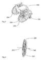
- FIG. 5 A typical example of a wheelchair for a sick or handicapped person is in Fig. 5 shown.
- a known wheelchair 400 has two large wheels 200, each having a gripping ring 220, by means of which the wheels can be driven by hand, that are manually driven.
- two significantly smaller wheels 230 are mounted on freely pivoting castors.
- the large wheels 200 are often designed to be easily removable.
- axles 240 and corresponding attachment means 250 are provided, by means of which the wheels 200 can be easily attached to the wheelchair frame 410 and removed again.
- auxiliary drive devices Such an auxiliary drive device, as in the FIGS. 7 to 10 is shown, for example, from the DE 198 57 786 C1 known.
- auxiliary drive devices As wheels 300 formed with a hub motor 330, also generally have a gripping ring 320, over which the person sitting in the wheelchair person can put the wheel in rotation with their hands.
- the electric hub motor 330 of the auxiliary drive device is driven in response to the torque, which is manually introduced into the gripping ring 320, for delivering a supplementary electrically generated torque, that is, an assist torque.
- the torque introduced manually into the gripping ring 320 is detected and supplied to an electronic controller, which then controls the electric motor designed as a hub motor 330 so that it emits an electrically generated torque.
- the from the DE 198 57 786 C1 known auxiliary drive device is designed as a self-contained unit in which the drive unit including a corresponding stator and a rotor of the electric motor, the power supply in the form of corresponding rechargeable batteries and the electronic control are provided in the wheel hub.
- torque support of a hub motor in an electrically driven wheel of a wheelchair is from the DE 199 49 405 C1 known.
- a torque arm is arranged on the wheelchair, are formed on the three webs.
- the Rear side of the stator of the electric motor of the electric drive device is provided with a plurality of grooves.
- the webs of the torque arm provided on the wheelchair engage in the grooves on the rear side of the stator and in this way constitute a torque support.
- Auxiliary drive devices and electrically driven wheels for wheelchairs of the type described above are products that are designed for economic use for use on a variety of different wheelchair frame. This has heretofore required that, for a given such auxiliary drive device in the form of an electric hub motor impeller, separate and specific torque support be developed for each wheelchair frame. This requires a considerable amount of time and costs.
- the market of manually driven wheelchairs in Germany alone includes several hundred different models.
- an electric auxiliary drive device for a wheelchair user is often only necessary or therapeutically useful if the wheelchair user has long used a first only manually driven wheelchair.
- a typical example of this is the decreasing physical strength of elderly wheelchair users, which makes it at some point necessary or at least desirable, the purely manual force by a supplement electric assistive power.
- a wheelchair user who is faced with the decision, if necessary, to use such an electric auxiliary drive device, this could try first.
- this due to the virtually unmanageable variety and number of different wheelchairs, this is usually not possible because an available on the market auxiliary drive device can not be mounted without a specially designed for this purpose axle on any wheelchair frame. The wheelchair user involved in such a decision must therefore test the auxiliary drive device in a trial wheelchair unfamiliar to him, which is generally perceived as unpleasant.
- the invention is therefore based on the object to improve the situation set out above and to provide a technical possibility that allows a wheelchair user to test provided with a hub motor drive wheels on his own wheelchair.
- the inventive solution is based in the concept of providing a Drehmomentabstützvorraum for mounting a provided with a hub motor drive wheel to a wheelchair, which allows an at least temporary fixation of an electric auxiliary drive device of the type in question on a wheelchair, to the previously only manually driven wheels mounted in a simple and fast way.
- the torque support device according to the invention is designed for this purpose so that in virtually all on the market wheelchairs a fixation with appropriate torque support is possible and yet can be fixed quickly and safely.
- the mounting element is preferably designed as a circular flange, which preferably has a plurality of slots.
- Fig. 1 shows a radial side view of an embodiment of a torque support device 1 according to the invention with a circular flange 10, a first circular cylindrical bolt 20 and a second circular cylindrical bolt 30.
- the flange 10 is a mounting member according to the present invention.
- the flange 10 preferably has a plurality of slots 11 which have a curved course in the illustrated embodiment. It is understood that the elongated holes 11 may have a variety of shapes including a straight course. It is also understood that depending on the shape and course and a single slot 11 may be sufficient.
- the elongated holes 11 are used for the variable attachment of the two bolts 20 and 30 to the flange 10, wherein both bolts 20, 30 on its in the assembled state of the flange 10 facing end side threaded pins 5 have.
- the bolts 20, 30 are freely slidable in the oblong holes 11.
- the flange 10 is rotatably connected to a stator (not shown) of a hub motor, which serves as an electric drive of an electrically driven drive wheel 300 of a wheelchair 400 according to the present invention, for example via cylindrical pins 15.
- the attachment of the flange 10 to an electrically driven Drive wheel 300, as exemplified in the FIGS. 8 to 10 is shown, can be done via screws 16.
- the flange plate 10 can also be fastened via one or more magnets to a stator or stator part of the hub motor of an electrically drivable drive wheel 300. This has the advantage that the flange can be mounted without tools if necessary.
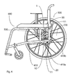
- Fig. 4 shows in a sectional side view of a wheelchair 400 to which an electrically driven drive wheel 300 by means of the Drehmomentabstützvorraum according to Fig. 1 is ready for use.
- the bolts 20, 30 are in the slots 11 of the flange 10 so shifted and fixed at the desired locations on the screws 5 and nuts 40 so that they abut Points or points 410a and 410b of the wheelchair frame to ensure rotation against both rotation of the stator of the hub motor 330 of the drive wheel 300 in the forward direction of the wheelchair 400 and in the reverse direction. It can thus be made in a simple and fast way, a fixation by positive engagement between the bolts 20, 30 and the wheelchair frame 410. By appropriate arrangement of the nuts 40 in guides along the slots 11, the fixation by simply rotating the bolts 20, 30 can be effected.
- a conversion of the type described above takes place in particular when a wheelchair, which was previously provided with wheels 200, which can be driven only manually via a gripping ring 220, is now to be provided with electric auxiliary drive devices in the form of electrically driven wheels 300.
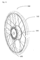
- Such electrically driven impeller 300 is in the Fig. 8 to 10 shown. It also has a gripping ring 320, via which manual driving force can be introduced, and additionally an electric hub motor 330.
Landscapes
- Health & Medical Sciences (AREA)
- Life Sciences & Earth Sciences (AREA)
- Animal Behavior & Ethology (AREA)
- General Health & Medical Sciences (AREA)
- Public Health (AREA)
- Veterinary Medicine (AREA)
- Arrangement Or Mounting Of Propulsion Units For Vehicles (AREA)
Abstract
Description
- Die Erfindung betrifft eine Drehmomentabstützvorrichtung zur Montage eines mit einem Nabenmotor versehenen Antriebsrades an einem Rollstuhl.
- Ein typisches Beispiel eines Rollstuhls für eine kranke oder gehbehinderte Person ist in
Fig. 5 dargestellt. Ein derartiger bekannter Rollstuhl 400 verfügt über zwei große Laufräder 200, die jeweils über einen Greifring 220 verfügen, mittels dessen die Laufräder von Hand angetrieben werden können, das heißt manuell antreibbar sind. Üblicherweise auf der in Fahrtrichtung vorderen Seite des Rollstuhls 400 sind zudem zwei deutlich kleinere Laufräder 230 an frei schwenkbaren Kastoren angebracht. - Zum leichteren Transport eines derartigen Rollstuhls 400 sind insbesondere die großen Laufräder 200 oftmals so ausgeführt, dass sie leicht abnehmbar sind. Zum leicht abnehmbaren Anbau eines derartigen Laufrades sind, wie in
Fig. 6 dargestellt, Steckachsen 240 und entsprechende Anbaumittel 250 vorgesehen, mittels derer die Laufräder 200 leicht an dem Rollstuhlrahmen 410 befestigt und wieder abgenommen werden können. - Es ist zudem bekannt, auch elektrisch antreibbare Laufräder eines Rollstuhls als abnehmbare Steckräder auszuführen. Ein derartiges elektrisch antreibbares Antriebsrad für einen Rollstuhl ist beispielsweise aus der
DE 41 27 257 A1 bekannt. - Es ist des Weiteren bekannt, derartige elektrische Antriebsräder für einen Rollstuhl als sogenannte Hilfsantriebsvorrichtungen auszuführen. Eine derartige Hilfsantriebsvorrichtung, wie sie in den
Figuren 7 bis 10 gezeigt ist, ist beispielsweise aus derDE 198 57 786 C1 bekannt. Derartige Hilfsantriebsvorrichtungen, als Laufräder 300 mit einem Nabenmotor 330 ausgebildet, weisen in der Regel ebenfalls einen Greifring 320 auf, über den die in dem Rollstuhl sitzende Person mit ihren Händen das Rad in Drehung versetzen kann. Der elektrische Nabenmotor 330 der Hilfsantriebsvorrichtung wird als Reaktion auf das Drehmoment, das von Hand in den Greifring 320 eingeleitet wird, zur Abgabe eines ergänzenden elektrisch erzeugten Drehmoments, das heißt eines Unterstützungsdrehmoments, angesteuert. Hierzu wird über Sensoren, beispielsweise solchen, wie sie in derDE 198 57 786 C1 offenbart, in denFiguren 7 bis 10 jedoch nicht gezeigt sind, das von Hand in den Greifring 320 eingeleitete Drehmoment erfasst und einer elektronischen Steuerung zugeführt, die den als Elektromotor ausgeführten Nabenmotor 330 daraufhin so ansteuert, dass dieser ein elektrisch erzeugtes Drehmoment abgibt. - Die aus der
DE 198 57 786 C1 bekannte Hilfsantriebsvorrichtung ist als selbstständige Einheit ausgeführt, bei der die Antriebseinheit einschließlich eines entsprechenden Stators und eines Rotors des Elektromotors, die Stromversorgung in Form entsprechender aufladbarer Batterien und die elektronische Steuerung in der Radnabe vorgesehen sind. - Wenn ein derartiges elektrisch antreibbares Laufrad mit einem Nabenmotor an einem Rollstuhl befestigt wird, so ist es erforderlich, eine sogenannte Drehmomentstütze oder Drehmomentabstützvorrichtung bereit zu stellen, die dafür Sorge trägt, dass der Stator des Elektromotors drehfest mit dem Rollstuhlgestell verbunden ist. Auf diese Weise kann durch Drehung des Rotors des Elektromotors gegenüber dem Stator des Elektromotors ein Drehen des Antriebsrades bewirkt werden. Bei der aus der
DE 41 27 257 A1 bekannten elektrischen Antriebsvorrichtung ist hierzu ein Steckrohr vorgesehen, das in eine an einem Rollstuhlgestell befestigte Adapterhülse einsteckbar ist. - Eine andere Form einer Drehmomentabstützung eines Nabenmotors bei einem elektrisch antreibbaren Rad eines Rollstuhls ist aus der
DE 199 49 405 C1 bekannt. Bei dieser bekannten Form der Drehmomentabstützung ist am Rollstuhl eine Drehmomentstütze angeordnet, auf der drei Stege ausgebildet sind. Die Rückseite des Stators des Elektromotors der elektrischen Antriebsvorrichtung ist mit einer Vielzahl von Nuten versehen. Im betriebsbereit montierten Zustand des elektrisch antreibbaren Antriebsrades greifen die Stege der am Rollstuhl vorgesehenen Drehmomentstütze in die Nuten auf der Rückseite des Stators ein und stellen auf diese Weise eine Drehmomentabstützung dar. - Bei allen bekannten Arten der Drehmomentabstützung ist es naturgemäß erforderlich, dass die beiden ineinandergreifenden Elemente, nämlich das am Stator der Antriebsvorrichtung angeordnete Element und das am Rollstuhlrahmen angeordnete Element, in einer solchen Weise bereitgestellt werden, dass sie auch tatsächlich ineinandergreifen können. Erforderlich ist somit nicht nur, dass die Formen und Abmessungen exakt aufeinander abgestimmt sind, sondern darüber hinaus auch, dass eine exakte lagemäßige Anordnung gegeben ist, die es erlaubt, dass das am Stator der Antriebsvorrichtung angeordnete Element dann, wenn das Antriebsrad an dem Rollstuhl befestigt ist, auch in das am Rollstuhlrahmen angeordnete Element eingreifen kann.
- Hilfsantriebsvorrichtungen und elektrisch antreibbare Laufräder für Rollstühle der vorstehend erläuterten Art sind Produkte, die aus wirtschaftlicher Notwendigkeit zur Verwendung an einer Vielzahl von unterschiedlichen Rollstuhlrahmen ausgelegt sind. Dies hat es bislang erforderlich gemacht, dass bei einer gegebenen derartigen Hilfsantriebsvorrichtung in Form eines Laufrades mit elektrischem Nabenmotor für jeden Rollstuhlrahmen eine separate und spezielle Drehmomentabstützung entwickelt werden muss. Dies bedingt einen erheblichen Aufwand an Zeit und Kosten. Der Markt von manuell antreibbaren Rollstühlen alleine in Deutschland umfasst mehrere hundert verschiedene Modelle.
- Die Benutzung einer elektrischen Hilfsantriebsvorrichtung für einen Rollstuhlfahrer wird oftmals erst dann erforderlich oder therapeutisch sinnvoll, wenn der Rollstuhlfahrer schon seit langem einen zunächst nur manuell antreibbaren Rollstuhl benutzt hat. Ein typisches Beispiel hierfür ist die bei älter werdenden Rollstuhlfahrern nachlassende körperliche Kraft, die es irgendwann erforderlich oder zumindest wünschenswert macht, die rein manuelle Kraft durch eine elektrisch unterstützende Kraft zu ergänzen. Naturgemäß wäre es hierbei wünschenswert, dass ein Rollstuhlfahrer, der vor der Entscheidung steht, gegebenenfalls eine derartige elektrische Hilfsantriebsvorrichtung zu verwenden, diese zunächst ausprobieren könnte. Aufgrund der praktisch unüberschaubaren Vielfalt und Anzahl verschiedener Rollstühle ist dies jedoch in der Regel nicht möglich, da eine auf dem Markt verfügbare Hilfsantriebsvorrichtung nicht ohne eine speziell hierfür ausgelegte Steckachse an einem beliebigen Rollstuhlgestell montiert werden kann. Der mit einer derartigen Entscheidung befasste Rollstuhlfahrer muss daher die Hilfsantriebsvorrichtung in einem für ihn ungewohnten Versuchsrollstuhl testen, was allgemein als unangenehm empfunden wird.
- Der Erfindung liegt damit die Aufgabe zugrunde, die vorstehend dargelegte Situation zu verbessern und eine technische Möglichkeit zu schaffen, die es einem Rollstuhlfahrer ermöglicht, mit einem Nabenmotor versehene Antriebsräder an seinem eigenen Rollstuhl zu testen.
- Die Lösung dieser Aufgabe ist in Patentanspruch 1 definiert. Vorteilhafte Ausgestaltungen sind in den Unteransprüchen angegeben.
- Die erfinderische Lösung fußt in dem Konzept, eine Drehmomentabstützvorrichtung zur Montage eines mit einem Nabenmotor versehenen Antriebsrades an einem Rollstuhl bereitzustellen, die es ermöglicht, eine zumindest vorübergehende Fixierung einer elektrischen Hilfsantriebsvorrichtung der in Rede stehenden Art an einem Rollstuhl, an dem bislang nur manuell antreibbare Räder montiert waren, auf einfache und schnelle Art zu ermöglichen. Die erfindungsgemäße Drehmomentabstützvorrichtung ist hierzu so gestaltet, dass bei praktisch allen auf dem Markt befindlichen Rollstühlen eine Fixierung mit entsprechender Drehmomentabstützung möglich ist und dennoch schnell und sicher fixiert werden kann.
- Die erfindungsgemäße Drehmomentabstützvorrichtung zur Montage eines mit einem Nabenmotor versehenen Antriebsrades an einem einen Rahmen aufweisenden Rollstuhl weist ein Montageelement auf, das drehfest mit einem Statorteil des Nabenmotors verbunden ist und mindestens ein Langloch aufweist, und zwei Bolzen, die längs des mindestens einen Langlochs verschiebbar und an einer solchen Position in Bezug auf das Montageelement fixierbar sind, dass sie an dem Rahmen des Rollstuhls anliegen und durch Formschluss ein Verdrehen des Statorteils des Nabenmotors des Antriebsrades in Vorwärtsrichtung des Rollstuhls als auch in dessen Rückwärtsrichtung verhindern. Das Montageelement ist vorzugsweise als eine kreisförmige Flanschscheibe ausgeführt, welche vorzugsweise mehrere Langlöcher aufweist.
- Vorteilhafte Ausgestaltungen der Erfindung werden nachfolgend unter Bezug auf die beigefügten Zeichnungen erläutert. Es zeigen
-
Fig. 1 eine Seitenansicht einer Ausführungsform einer erfindungsgemäßen Drehmomentabstützvorrichtung in radialer Richtung, -
Fig. 2 eine Draufsicht der Drehmomentabstützvorrichtung gemäßFig. 1 in Richtung des Pfeiles A inFig. 1 , -
Fig. 3 eine Draufsicht der Drehmomentabstützvorrichtung gemäßFig. 1 entgegen der Richtung des Pfeiles A inFig. 1 , -
Fig. 4 eine Seitenansicht eines mittig geschnittenen Rollstuhls, an dem ein elektrisch antreibbares Antriebsrad mittels der Drehmomentabstützvorrichtung gemäßFig. 1 betriebsbereit montiert ist, -
Fig. 5 eine perspektivische Darstellung eines Rollstuhls mit manuell antreibbaren Laufrädern, -
Fig. 6 eine auseinandergezogene perspektivische Darstellung eines manuell antreibbaren Laufrads mit einer Steckachse und einer Adapterhülse, -
Fig. 7 eine perspektivische Darstellung eines Rollstuhls gemäßFig. 5 , an dem ein elektrisch antreibbares Antriebsrad befestigt ist und ein weiteres elektrisch antreibbares Antriebsrad zusammen mit entsprechenden Anbauteilen einschließlich einer Steckachse auseinandergezogen dargestellt ist, -
Fig. 8 eine perspektivische Darstellung eines elektrisch antreibbaren Antriebsrades von der in einem an einem Rollstuhl betriebsbereit montierten Zustand von dem Rollstuhl wegzeigenden Seite aus gesehen, -
Fig. 9 das elektrisch antreibbare Antriebsrad gemäßFig. 8 von der in einem an einem Rollstuhl betriebsbereit montieren Zustand dem Rollstuhl zugewandten Seite aus gesehen zusammen mit der durch das elektrisch antreibbare Antriebsrad durchgesteckten Steckachse und -
Fig. 10 eine vergrößerte Darstellung des elektrisch antreibbaren Antriebsrades gemäßFig. 9 . -
Fig. 1 zeigt in einer radialen Seitenansicht eine Ausführungsform einer erfindungsgemäßen Drehmomentabstützvorrichtung 1 mit einer kreisförmigen Flanschscheibe 10, einem ersten kreiszylindrischen Bolzen 20 und einem zweiten kreiszylindrischen Bolzen 30. Die Flanschscheibe 10 ist ein Montageelement im Sinne der vorliegenden Erfindung. - Wie in den
Figuren 2 und 3 gezeigt, weist die Flanschscheibe 10 vorzugsweise mehrere Langlöcher 11 auf, die in der dargestellten Ausführungsform einen geschwungenen Verlauf aufweisen. Es versteht sich, dass die Langlöcher 11 eine Vielzahl von Formen einschließlich eines geraden Verlaufes aufweisen können. Es versteht sich zudem, dass je nach Form und Verlauf auch ein einziges Langloch 11 ausreichend sein kann. - Die Langlöcher 11 dienen der variablen Befestigung der beiden Bolzen 20 und 30 an der Flanschscheibe 10, wobei beide Bolzen 20, 30 auf ihrer im montierten Zustand der Flanschscheibe 10 zugewandten Stirnseite Gewindestifte 5 aufweisen. Die Bolzen 20, 30 sind in den Langlöchern 11 frei verschiebbar.
- Die Befestigung der Bolzen 20, 30 an einer gewünschten Stelle längs der Langlöcher 11 erfolgt über die Gewindestifte 5, die jeweils durch ein Langloch 11 hindurchgesteckt sind, und Muttern 40, die von der den Bolzen 20, 30 abgewandten Seite der Flanschscheibe 10 her auf die Gewindestifte 5 aufgeschraubt sind.
- Die Flanschscheibe 10 ist mit einem Statorteil (nicht gezeigt) eines Nabenmotors, der als elektrischer Antrieb eines elektrisch antreibbaren Antriebsrades 300 eines Rollstuhls 400 im Sinne der vorliegenden Erfindung dient, drehfest verbunden, beispielsweise über Zylinderstifte 15. Die Befestigung der Flanschscheibe 10 an einem elektrisch antreibbaren Antriebsrad 300, wie es beispielhaft in den
Figuren 8 bis 10 gezeigt ist, kann über Schrauben 16 erfolgen. Es versteht sich für den Fachmann, dass alternativ hierzu auch andere Befestigungsmöglichkeiten bestehen. So kann die Flanschscheibe 10 beispielsweise auch über einen oder mehrere Magnete an einem Stator beziehungsweise Statorteil des Nabenmotors eines elektrisch antreibbaren Antriebsrades 300 befestigt werden. Dies hat den Vorteil, dass die Flanschscheibe bei Bedarf werkzeuglos montiert werden kann. -
Fig. 4 zeigt in einer seitlichen Schnittansicht einen Rollstuhl 400, an dem ein elektrisch antreibbares Antriebsrad 300 mittels der Drehmomentabstützvorrichtung gemäßFig. 1 betriebsbereit montiert ist. Die Lagerung und axiale Fixierung des elektrisch antreibbaren Antriebsrades 300 an dem Rahmen 410 des Rollstuhls 400 erfolgt über eine Steckachse 500. Die Verdrehsicherung des Statorteils (nicht gezeigt) und damit die Drehmomentabstützung des Nabenmotors 330 gegenüber dem Rollstuhlrahmen 410 erfolgt über die zuvor beschriebene Drehmomentabstützvorrichtung 1 mit der Flanschscheibe 10, dem ersten Bolzen 20 und dem zweiten Bolzen 30. Die Bolzen 20, 30 sind in den Langlöchern 11 der Flanschscheibe 10 so verschoben und an den gewünschten Stellen über die Gewindestifte 5 und die Muttern 40 so fixiert, dass sie in Anlage an Punkten beziehungsweise Stellen 410a und 410b des Rollstuhlrahmens eine Drehsicherung sowohl gegen ein Drehen des Statorteils des Nabenmotors 330 des Antriebsrades 300 in Vorwärtsrichtung des Rollstuhls 400 als auch in dessen Rückwärtsrichtung gewährleisten. Es kann somit auf einfache und schnelle Art und Weise eine Fixierung durch Formschluss zwischen den Bolzen 20, 30 und dem Rollstuhlrahmen 410 hergestellt werden. Durch entsprechende Anordnung der Muttern 40 in Führungen längs der Langlöcher 11 kann die Fixierung durch einfaches Verdrehen der Bolzen 20, 30 bewirkt werden. - Ein Umbau der vorstehend erläuterten Art erfolgt insbesondere dann, wenn ein Rollstuhl, der bislang mit Laufrädern 200 versehen war, welche sich über einen Greifring 220 lediglich manuell antreiben lassen, nunmehr mit elektrischen Hilfsantriebsvorrichtungen in Form elektrisch antreibbarer Laufräder 300 versehen werden soll. Ein derartiges elektrisch antreibbares Laufrad 300 ist in den
Fig. 8 bis 10 dargestellt. Es verfügt ebenfalls über einen Greifring 320, über den von Hand Antriebskraft eingeleitet werden kann, und zusätzlich über einen elektrischen Nabenmotor 330. In den Figuren nicht dargestellt ist eine aus dem Stand der Technik bekannte Sensoreinrichtung, mittels derer die Größe und Richtung der manuell in den Greifring 320 eingeleiteten Kraft gemessen werden kann, sowie eine ebenfalls aus dem Stand der Technik bekannte Steuereinrichtung, die das Signal der Sensoreinrichtung verarbeitet und den elektrischen Nabenmotor 330 so ansteuert, dass er gemäß einem entsprechenden Unterstützungsgrad ein elektrisch erzeugtes Drehmoment abgibt, welches die manuell eingeleitete Kraft unterstützt.
Claims (8)
- Drehmomentabstützvorrichtung zur Montage eines mit einem Nabenmotor (330) versehenen Antriebsrades (300) an einem einen Rahmen (410) aufweisenden Rollstuhl (400),
gekennzeichnet durch
ein Montageelement (10), das drehfest mit einem Statorteil des Nabenmotors (330) verbunden ist und mindestens ein Langloch (11) aufweist, und
zwei Bolzen (20, 30), die längs des mindestens einen Langlochs (11) an einer solchen Position in Bezug auf das Montageelement (10) fixierbar sind, dass sie an dem Rahmen (410) des Rollstuhls (400) anliegen und durch Formschluss ein Verdrehen des Statorteils des Nabenmotors (330) des Antriebsrades (300) in Vorwärtsrichtung des Rollstuhls (400) als auch in dessen Rückwärtsrichtung verhindern. - Drehmomentabstützvorrichtung nach Anspruch 1, dadurch gekennzeichnet, dass das Montageelement (10) eine kreisförmige Flanschscheibe ist.
- Drehmomentabstützvorrichtung nach Anspruch 1 oder 2, dadurch gekennzeichnet, dass eine Mehrzahl an Langlöchern (11) vorgesehen ist.
- Drehmomentabstützvorrichtung nach Anspruch 1, 2 oder 3, dadurch gekennzeichnet, dass das Langloch (11) beziehungsweise die Langlöcher (11) geschwungen ausgeführt sind.
- Drehmomentabstützvorrichtung nach einem der vorstehenden Ansprüche, dadurch gekennzeichnet, dass die Bolzen (20, 30) kreiszylindrisch ausgeführt sind.
- Drehmomentabstützvorrichtung nach einem der vorstehenden Ansprüche, dadurch gekennzeichnet, dass die Bolzen (20, 30) Gewindestifte (5) aufweisen, mittels derer diese an Positionen längs eines Langlochs (11) fixierbar sind.
- Drehmomentabstützvorrichtung nach Anspruch 6, dadurch gekennzeichnet, dass die Bolzen (20, 30) über mit den Gewindestiften (5) verschraubte Muttern (40) fixierbar sind.
- Drehmomentabstützvorrichtung nach Anspruch 7, dadurch gekennzeichnet, dass die Muttern (40) in Führungen längs der Langlöcher (11) geführt sind.
Applications Claiming Priority (1)
| Application Number | Priority Date | Filing Date | Title |
|---|---|---|---|
| DE102013109863.0A DE102013109863B4 (de) | 2013-09-10 | 2013-09-10 | 2Drehmomentabstützvorrichtung zur Montage eines mit einem Nabenmotor versehenen Antriebsrades an einem Rollstuhl |
Publications (3)
| Publication Number | Publication Date |
|---|---|
| EP2848237A2 true EP2848237A2 (de) | 2015-03-18 |
| EP2848237A3 EP2848237A3 (de) | 2015-04-29 |
| EP2848237B1 EP2848237B1 (de) | 2016-05-18 |
Family
ID=51483237
Family Applications (1)
| Application Number | Title | Priority Date | Filing Date |
|---|---|---|---|
| EP14183092.7A Not-in-force EP2848237B1 (de) | 2013-09-10 | 2014-09-01 | Drehmomentabstützvorrichtung zur montage eines mit einem nabenmotor versehenen antriebsrades an einem rollstuhl |
Country Status (3)
| Country | Link |
|---|---|
| EP (1) | EP2848237B1 (de) |
| DE (1) | DE102013109863B4 (de) |
| DK (1) | DK2848237T3 (de) |
Cited By (1)
| Publication number | Priority date | Publication date | Assignee | Title |
|---|---|---|---|---|
| CN110638583A (zh) * | 2019-09-24 | 2020-01-03 | 刘玉辉 | 一种儿科复健自动轮椅 |
Families Citing this family (1)
| Publication number | Priority date | Publication date | Assignee | Title |
|---|---|---|---|---|
| DE102023213239A1 (de) * | 2023-12-21 | 2025-06-26 | Otto Bock Mobility Solutions Gmbh | Rollstuhl |
Citations (3)
| Publication number | Priority date | Publication date | Assignee | Title |
|---|---|---|---|---|
| DE4127257A1 (de) | 1991-08-17 | 1993-02-18 | Haas & Alber Haustechnik Und A | Kleinfahrzeug, insbesondere rollstuhl mit faltbarem stuhlgestell |
| DE19857786C2 (de) | 1998-03-21 | 2000-05-31 | Alber Ulrich Gmbh & Co Kg | Hilfsantriebsvorrichtung für Selbstfahrer-Rollstühle |
| DE19949405C1 (de) | 1999-10-13 | 2000-10-26 | Alber Ulrich Gmbh | Fahrzeug, insbesondere Rollstuhl |
Family Cites Families (5)
| Publication number | Priority date | Publication date | Assignee | Title |
|---|---|---|---|---|
| DE19708058A1 (de) * | 1997-02-28 | 1998-09-03 | Bock Orthopaed Ind | Muskelbetriebenes Radfahrzeug |
| AU6130899A (en) * | 1998-10-30 | 2000-05-22 | Invacare Corporation | Power wheelchair having a brushless, gearless motor and utilizing a trapezoidal wave function drive controller |
| JP3569214B2 (ja) * | 2000-09-18 | 2004-09-22 | 株式会社上田トーコー | 座幅可変車椅子 |
| DE102004039519B3 (de) * | 2004-08-14 | 2005-06-30 | Otto Bock Healthcare Gmbh | Laufradanordnung für einen Rollstuhl |
| JP4712465B2 (ja) * | 2005-07-20 | 2011-06-29 | ヤマハ発動機株式会社 | 回転電機及び電動車椅子 |
-
2013
- 2013-09-10 DE DE102013109863.0A patent/DE102013109863B4/de not_active Expired - Fee Related
-
2014
- 2014-09-01 DK DK14183092.7T patent/DK2848237T3/en active
- 2014-09-01 EP EP14183092.7A patent/EP2848237B1/de not_active Not-in-force
Patent Citations (3)
| Publication number | Priority date | Publication date | Assignee | Title |
|---|---|---|---|---|
| DE4127257A1 (de) | 1991-08-17 | 1993-02-18 | Haas & Alber Haustechnik Und A | Kleinfahrzeug, insbesondere rollstuhl mit faltbarem stuhlgestell |
| DE19857786C2 (de) | 1998-03-21 | 2000-05-31 | Alber Ulrich Gmbh & Co Kg | Hilfsantriebsvorrichtung für Selbstfahrer-Rollstühle |
| DE19949405C1 (de) | 1999-10-13 | 2000-10-26 | Alber Ulrich Gmbh | Fahrzeug, insbesondere Rollstuhl |
Cited By (1)
| Publication number | Priority date | Publication date | Assignee | Title |
|---|---|---|---|---|
| CN110638583A (zh) * | 2019-09-24 | 2020-01-03 | 刘玉辉 | 一种儿科复健自动轮椅 |
Also Published As
| Publication number | Publication date |
|---|---|
| DE102013109863B4 (de) | 2016-11-03 |
| DE102013109863A1 (de) | 2015-03-12 |
| EP2848237A3 (de) | 2015-04-29 |
| EP2848237B1 (de) | 2016-05-18 |
| DK2848237T3 (en) | 2016-08-29 |
Similar Documents
| Publication | Publication Date | Title |
|---|---|---|
| DE102012016312B4 (de) | Elektrische Servolenkungsvorrichtung | |
| DE102019106042A1 (de) | Lenkradsysteme und drehmomentrückkopplungsaktoranordnungen zur verwendung in steer-by-wire-fahrzeugen | |
| EP3242802B1 (de) | Mobiles medizinisches gerät mit mindestens einem motorisch angetriebenen rad | |
| DE102016118032A1 (de) | Antriebseinheit und Rollstuhl mit Antriebseinheit | |
| EP0428895A2 (de) | Stellantrieb | |
| EP2733262B1 (de) | Kehrgerät für ein Kinderfahrzeug, insbesondere für ein Tretfahrzeug | |
| EP2848237B1 (de) | Drehmomentabstützvorrichtung zur montage eines mit einem nabenmotor versehenen antriebsrades an einem rollstuhl | |
| DE102015003107B4 (de) | Fahrzeug und Verfahren zum Herstellen verschiedener Varianten eines Fahrzeugs | |
| DE2914844C2 (de) | Schnellspannvorrichtung, insbesondere für Auswuchtmaschinen zum Auswuchten von Fahrzeugrädern | |
| DE69104064T2 (de) | Antriebseinheit für fortbewegungshilfe eines handgetriebenen rollstuhls. | |
| EP2431016B1 (de) | Vorrichtung zum Anheben und Wenden eines Patienten | |
| EP2511152A1 (de) | Lenkradbetätigungsvorrichtung | |
| EP3252259B1 (de) | Antriebsvorrichtung eines rollladens und rollladen | |
| DE102013109865A1 (de) | Steckachse zur Montage eines Rades an einem Rollstuhl | |
| DE102018129157A1 (de) | Bremsanordnung für ein Laufrad eines Rollstuhls, Laufrad und Rollstuhl | |
| EP1092407B2 (de) | Fahrzeug, insbesondere Rollstuhl | |
| DE102013109868A1 (de) | Bausatz zur Montage einer Hilfsantriebsvorrichtung an einem Rollstuhl | |
| DE102010037705A1 (de) | Hilfsantriebsvorrichtung, Rollstuhl und Verfahren zur Ermittlung der manuellen Antriebskraft eines Rollstuhlfahrers | |
| DE112015005837T5 (de) | Antrieb eines Räderfahrzeugs, insbesondere eines Fahrrads | |
| DE4229556A1 (de) | Vorrichtung zum Anheben eines Fahrzeuges | |
| DE3403092A1 (de) | Hobelmaschine | |
| EP2894089A1 (de) | Set mit Elektromotor für Fahrräder | |
| DE102016226144B4 (de) | Antriebsanordnung und Verfahren zu deren Herstellung sowie Fahrzeugsitz | |
| DE20203791U1 (de) | Kniehebelspannvorrichtung | |
| EP3770098A1 (de) | Treppenlift und verfahren zum betreiben eines treppenlifts |
Legal Events
| Date | Code | Title | Description |
|---|---|---|---|
| PUAI | Public reference made under article 153(3) epc to a published international application that has entered the european phase |
Free format text: ORIGINAL CODE: 0009012 |
|
| 17P | Request for examination filed |
Effective date: 20140901 |
|
| AK | Designated contracting states |
Kind code of ref document: A2 Designated state(s): AL AT BE BG CH CY CZ DE DK EE ES FI FR GB GR HR HU IE IS IT LI LT LU LV MC MK MT NL NO PL PT RO RS SE SI SK SM TR |
|
| AX | Request for extension of the european patent |
Extension state: BA ME |
|
| PUAL | Search report despatched |
Free format text: ORIGINAL CODE: 0009013 |
|
| AK | Designated contracting states |
Kind code of ref document: A3 Designated state(s): AL AT BE BG CH CY CZ DE DK EE ES FI FR GB GR HR HU IE IS IT LI LT LU LV MC MK MT NL NO PL PT RO RS SE SI SK SM TR |
|
| AX | Request for extension of the european patent |
Extension state: BA ME |
|
| RIC1 | Information provided on ipc code assigned before grant |
Ipc: A61G 5/10 20060101ALN20150324BHEP Ipc: A61G 5/04 20130101ALI20150324BHEP Ipc: A61G 5/02 20060101AFI20150324BHEP |
|
| R17P | Request for examination filed (corrected) |
Effective date: 20150805 |
|
| RBV | Designated contracting states (corrected) |
Designated state(s): AL AT BE BG CH CY CZ DE DK EE ES FI FR GB GR HR HU IE IS IT LI LT LU LV MC MK MT NL NO PL PT RO RS SE SI SK SM TR |
|
| RIC1 | Information provided on ipc code assigned before grant |
Ipc: A61G 5/02 20060101AFI20151215BHEP Ipc: A61G 5/04 20130101ALI20151215BHEP Ipc: A61G 5/10 20060101ALN20151215BHEP |
|
| GRAP | Despatch of communication of intention to grant a patent |
Free format text: ORIGINAL CODE: EPIDOSNIGR1 |
|
| INTG | Intention to grant announced |
Effective date: 20160127 |
|
| GRAS | Grant fee paid |
Free format text: ORIGINAL CODE: EPIDOSNIGR3 |
|
| GRAA | (expected) grant |
Free format text: ORIGINAL CODE: 0009210 |
|
| AK | Designated contracting states |
Kind code of ref document: B1 Designated state(s): AL AT BE BG CH CY CZ DE DK EE ES FI FR GB GR HR HU IE IS IT LI LT LU LV MC MK MT NL NO PL PT RO RS SE SI SK SM TR |
|
| REG | Reference to a national code |
Ref country code: GB Ref legal event code: FG4D Free format text: NOT ENGLISH |
|
| REG | Reference to a national code |
Ref country code: CH Ref legal event code: EP |
|
| REG | Reference to a national code |
Ref country code: IE Ref legal event code: FG4D Free format text: LANGUAGE OF EP DOCUMENT: GERMAN Ref country code: AT Ref legal event code: REF Ref document number: 799763 Country of ref document: AT Kind code of ref document: T Effective date: 20160615 |
|
| REG | Reference to a national code |
Ref country code: DE Ref legal event code: R096 Ref document number: 502014000793 Country of ref document: DE |
|
| REG | Reference to a national code |
Ref country code: CH Ref legal event code: NV Representative=s name: LATSCHA SCHOELLHORN PARTNER AG, CH |
|
| REG | Reference to a national code |
Ref country code: SE Ref legal event code: TRGR |
|
| REG | Reference to a national code |
Ref country code: NL Ref legal event code: FP |
|
| REG | Reference to a national code |
Ref country code: DK Ref legal event code: T3 Effective date: 20160823 |
|
| REG | Reference to a national code |
Ref country code: NO Ref legal event code: T2 Effective date: 20160518 |
|
| REG | Reference to a national code |
Ref country code: FR Ref legal event code: PLFP Year of fee payment: 3 |
|
| REG | Reference to a national code |
Ref country code: LT Ref legal event code: MG4D |
|
| PG25 | Lapsed in a contracting state [announced via postgrant information from national office to epo] |
Ref country code: LT Free format text: LAPSE BECAUSE OF FAILURE TO SUBMIT A TRANSLATION OF THE DESCRIPTION OR TO PAY THE FEE WITHIN THE PRESCRIBED TIME-LIMIT Effective date: 20160518 Ref country code: FI Free format text: LAPSE BECAUSE OF FAILURE TO SUBMIT A TRANSLATION OF THE DESCRIPTION OR TO PAY THE FEE WITHIN THE PRESCRIBED TIME-LIMIT Effective date: 20160518 |
|
| PG25 | Lapsed in a contracting state [announced via postgrant information from national office to epo] |
Ref country code: GR Free format text: LAPSE BECAUSE OF FAILURE TO SUBMIT A TRANSLATION OF THE DESCRIPTION OR TO PAY THE FEE WITHIN THE PRESCRIBED TIME-LIMIT Effective date: 20160819 Ref country code: RS Free format text: LAPSE BECAUSE OF FAILURE TO SUBMIT A TRANSLATION OF THE DESCRIPTION OR TO PAY THE FEE WITHIN THE PRESCRIBED TIME-LIMIT Effective date: 20160518 Ref country code: LV Free format text: LAPSE BECAUSE OF FAILURE TO SUBMIT A TRANSLATION OF THE DESCRIPTION OR TO PAY THE FEE WITHIN THE PRESCRIBED TIME-LIMIT Effective date: 20160518 Ref country code: ES Free format text: LAPSE BECAUSE OF FAILURE TO SUBMIT A TRANSLATION OF THE DESCRIPTION OR TO PAY THE FEE WITHIN THE PRESCRIBED TIME-LIMIT Effective date: 20160518 Ref country code: HR Free format text: LAPSE BECAUSE OF FAILURE TO SUBMIT A TRANSLATION OF THE DESCRIPTION OR TO PAY THE FEE WITHIN THE PRESCRIBED TIME-LIMIT Effective date: 20160518 Ref country code: PT Free format text: LAPSE BECAUSE OF FAILURE TO SUBMIT A TRANSLATION OF THE DESCRIPTION OR TO PAY THE FEE WITHIN THE PRESCRIBED TIME-LIMIT Effective date: 20160919 |
|
| PG25 | Lapsed in a contracting state [announced via postgrant information from national office to epo] |
Ref country code: IT Free format text: LAPSE BECAUSE OF FAILURE TO SUBMIT A TRANSLATION OF THE DESCRIPTION OR TO PAY THE FEE WITHIN THE PRESCRIBED TIME-LIMIT Effective date: 20160518 |
|
| PG25 | Lapsed in a contracting state [announced via postgrant information from national office to epo] |
Ref country code: SK Free format text: LAPSE BECAUSE OF FAILURE TO SUBMIT A TRANSLATION OF THE DESCRIPTION OR TO PAY THE FEE WITHIN THE PRESCRIBED TIME-LIMIT Effective date: 20160518 Ref country code: CZ Free format text: LAPSE BECAUSE OF FAILURE TO SUBMIT A TRANSLATION OF THE DESCRIPTION OR TO PAY THE FEE WITHIN THE PRESCRIBED TIME-LIMIT Effective date: 20160518 Ref country code: RO Free format text: LAPSE BECAUSE OF FAILURE TO SUBMIT A TRANSLATION OF THE DESCRIPTION OR TO PAY THE FEE WITHIN THE PRESCRIBED TIME-LIMIT Effective date: 20160518 Ref country code: EE Free format text: LAPSE BECAUSE OF FAILURE TO SUBMIT A TRANSLATION OF THE DESCRIPTION OR TO PAY THE FEE WITHIN THE PRESCRIBED TIME-LIMIT Effective date: 20160518 |
|
| REG | Reference to a national code |
Ref country code: DE Ref legal event code: R097 Ref document number: 502014000793 Country of ref document: DE |
|
| PG25 | Lapsed in a contracting state [announced via postgrant information from national office to epo] |
Ref country code: BE Free format text: LAPSE BECAUSE OF NON-PAYMENT OF DUE FEES Effective date: 20160930 Ref country code: PL Free format text: LAPSE BECAUSE OF FAILURE TO SUBMIT A TRANSLATION OF THE DESCRIPTION OR TO PAY THE FEE WITHIN THE PRESCRIBED TIME-LIMIT Effective date: 20160518 Ref country code: SM Free format text: LAPSE BECAUSE OF FAILURE TO SUBMIT A TRANSLATION OF THE DESCRIPTION OR TO PAY THE FEE WITHIN THE PRESCRIBED TIME-LIMIT Effective date: 20160518 |
|
| PLBE | No opposition filed within time limit |
Free format text: ORIGINAL CODE: 0009261 |
|
| STAA | Information on the status of an ep patent application or granted ep patent |
Free format text: STATUS: NO OPPOSITION FILED WITHIN TIME LIMIT |
|
| 26N | No opposition filed |
Effective date: 20170221 |
|
| PG25 | Lapsed in a contracting state [announced via postgrant information from national office to epo] |
Ref country code: MC Free format text: LAPSE BECAUSE OF FAILURE TO SUBMIT A TRANSLATION OF THE DESCRIPTION OR TO PAY THE FEE WITHIN THE PRESCRIBED TIME-LIMIT Effective date: 20160518 |
|
| PG25 | Lapsed in a contracting state [announced via postgrant information from national office to epo] |
Ref country code: SI Free format text: LAPSE BECAUSE OF FAILURE TO SUBMIT A TRANSLATION OF THE DESCRIPTION OR TO PAY THE FEE WITHIN THE PRESCRIBED TIME-LIMIT Effective date: 20160518 |
|
| REG | Reference to a national code |
Ref country code: IE Ref legal event code: MM4A |
|
| PG25 | Lapsed in a contracting state [announced via postgrant information from national office to epo] |
Ref country code: IE Free format text: LAPSE BECAUSE OF NON-PAYMENT OF DUE FEES Effective date: 20160901 |
|
| PG25 | Lapsed in a contracting state [announced via postgrant information from national office to epo] |
Ref country code: LU Free format text: LAPSE BECAUSE OF NON-PAYMENT OF DUE FEES Effective date: 20160901 |
|
| REG | Reference to a national code |
Ref country code: FR Ref legal event code: PLFP Year of fee payment: 4 |
|
| REG | Reference to a national code |
Ref country code: BE Ref legal event code: MM Effective date: 20160930 |
|
| PG25 | Lapsed in a contracting state [announced via postgrant information from national office to epo] |
Ref country code: HU Free format text: LAPSE BECAUSE OF FAILURE TO SUBMIT A TRANSLATION OF THE DESCRIPTION OR TO PAY THE FEE WITHIN THE PRESCRIBED TIME-LIMIT; INVALID AB INITIO Effective date: 20140901 |
|
| PG25 | Lapsed in a contracting state [announced via postgrant information from national office to epo] |
Ref country code: MT Free format text: LAPSE BECAUSE OF FAILURE TO SUBMIT A TRANSLATION OF THE DESCRIPTION OR TO PAY THE FEE WITHIN THE PRESCRIBED TIME-LIMIT Effective date: 20160518 Ref country code: CY Free format text: LAPSE BECAUSE OF FAILURE TO SUBMIT A TRANSLATION OF THE DESCRIPTION OR TO PAY THE FEE WITHIN THE PRESCRIBED TIME-LIMIT Effective date: 20160518 Ref country code: MK Free format text: LAPSE BECAUSE OF FAILURE TO SUBMIT A TRANSLATION OF THE DESCRIPTION OR TO PAY THE FEE WITHIN THE PRESCRIBED TIME-LIMIT Effective date: 20160518 Ref country code: IS Free format text: LAPSE BECAUSE OF FAILURE TO SUBMIT A TRANSLATION OF THE DESCRIPTION OR TO PAY THE FEE WITHIN THE PRESCRIBED TIME-LIMIT Effective date: 20160518 |
|
| PG25 | Lapsed in a contracting state [announced via postgrant information from national office to epo] |
Ref country code: BG Free format text: LAPSE BECAUSE OF FAILURE TO SUBMIT A TRANSLATION OF THE DESCRIPTION OR TO PAY THE FEE WITHIN THE PRESCRIBED TIME-LIMIT Effective date: 20160518 |
|
| REG | Reference to a national code |
Ref country code: FR Ref legal event code: PLFP Year of fee payment: 5 |
|
| PG25 | Lapsed in a contracting state [announced via postgrant information from national office to epo] |
Ref country code: TR Free format text: LAPSE BECAUSE OF FAILURE TO SUBMIT A TRANSLATION OF THE DESCRIPTION OR TO PAY THE FEE WITHIN THE PRESCRIBED TIME-LIMIT Effective date: 20160518 Ref country code: AL Free format text: LAPSE BECAUSE OF FAILURE TO SUBMIT A TRANSLATION OF THE DESCRIPTION OR TO PAY THE FEE WITHIN THE PRESCRIBED TIME-LIMIT Effective date: 20160518 |
|
| PGFP | Annual fee paid to national office [announced via postgrant information from national office to epo] |
Ref country code: FR Payment date: 20180621 Year of fee payment: 15 |
|
| REG | Reference to a national code |
Ref country code: CH Ref legal event code: PCAR Free format text: NEW ADDRESS: GRELLINGERSTRASSE 60, 4052 BASEL (CH) |
|
| PGFP | Annual fee paid to national office [announced via postgrant information from national office to epo] |
Ref country code: SE Payment date: 20180924 Year of fee payment: 5 Ref country code: DK Payment date: 20180924 Year of fee payment: 5 Ref country code: GB Payment date: 20180924 Year of fee payment: 5 |
|
| PGFP | Annual fee paid to national office [announced via postgrant information from national office to epo] |
Ref country code: NL Payment date: 20190923 Year of fee payment: 6 Ref country code: DE Payment date: 20190927 Year of fee payment: 6 Ref country code: NO Payment date: 20190920 Year of fee payment: 6 |
|
| REG | Reference to a national code |
Ref country code: DK Ref legal event code: EBP Effective date: 20190930 |
|
| PG25 | Lapsed in a contracting state [announced via postgrant information from national office to epo] |
Ref country code: SE Free format text: LAPSE BECAUSE OF NON-PAYMENT OF DUE FEES Effective date: 20190902 |
|
| REG | Reference to a national code |
Ref country code: SE Ref legal event code: EUG |
|
| REG | Reference to a national code |
Ref country code: CH Ref legal event code: PL |
|
| PG25 | Lapsed in a contracting state [announced via postgrant information from national office to epo] |
Ref country code: LI Free format text: LAPSE BECAUSE OF NON-PAYMENT OF DUE FEES Effective date: 20190930 Ref country code: CH Free format text: LAPSE BECAUSE OF NON-PAYMENT OF DUE FEES Effective date: 20190930 |
|
| GBPC | Gb: european patent ceased through non-payment of renewal fee |
Effective date: 20190901 |
|
| PG25 | Lapsed in a contracting state [announced via postgrant information from national office to epo] |
Ref country code: GB Free format text: LAPSE BECAUSE OF NON-PAYMENT OF DUE FEES Effective date: 20190901 Ref country code: DK Free format text: LAPSE BECAUSE OF NON-PAYMENT OF DUE FEES Effective date: 20190930 Ref country code: FR Free format text: LAPSE BECAUSE OF NON-PAYMENT OF DUE FEES Effective date: 20190930 |
|
| REG | Reference to a national code |
Ref country code: AT Ref legal event code: MM01 Ref document number: 799763 Country of ref document: AT Kind code of ref document: T Effective date: 20190901 |
|
| PG25 | Lapsed in a contracting state [announced via postgrant information from national office to epo] |
Ref country code: AT Free format text: LAPSE BECAUSE OF NON-PAYMENT OF DUE FEES Effective date: 20190901 |
|
| REG | Reference to a national code |
Ref country code: DE Ref legal event code: R119 Ref document number: 502014000793 Country of ref document: DE |
|
| REG | Reference to a national code |
Ref country code: NO Ref legal event code: MMEP |
|
| REG | Reference to a national code |
Ref country code: NL Ref legal event code: MM Effective date: 20201001 |
|
| PG25 | Lapsed in a contracting state [announced via postgrant information from national office to epo] |
Ref country code: NL Free format text: LAPSE BECAUSE OF NON-PAYMENT OF DUE FEES Effective date: 20201001 |
|
| PG25 | Lapsed in a contracting state [announced via postgrant information from national office to epo] |
Ref country code: NO Free format text: LAPSE BECAUSE OF NON-PAYMENT OF DUE FEES Effective date: 20200930 Ref country code: DE Free format text: LAPSE BECAUSE OF NON-PAYMENT OF DUE FEES Effective date: 20210401 |