EP2848453B1 - Véhicule comprenant bobine de réception d'énergie - Google Patents
Véhicule comprenant bobine de réception d'énergie Download PDFInfo
- Publication number
- EP2848453B1 EP2848453B1 EP12876151.7A EP12876151A EP2848453B1 EP 2848453 B1 EP2848453 B1 EP 2848453B1 EP 12876151 A EP12876151 A EP 12876151A EP 2848453 B1 EP2848453 B1 EP 2848453B1
- Authority
- EP
- European Patent Office
- Prior art keywords
- coil
- power
- winding axis
- reception unit
- power reception
- Prior art date
- Legal status (The legal status is an assumption and is not a legal conclusion. Google has not performed a legal analysis and makes no representation as to the accuracy of the status listed.)
- Active
Links
Images


Classifications
-
- B—PERFORMING OPERATIONS; TRANSPORTING
- B60—VEHICLES IN GENERAL
- B60K—ARRANGEMENT OR MOUNTING OF PROPULSION UNITS OR OF TRANSMISSIONS IN VEHICLES; ARRANGEMENT OR MOUNTING OF PLURAL DIVERSE PRIME-MOVERS IN VEHICLES; AUXILIARY DRIVES FOR VEHICLES; INSTRUMENTATION OR DASHBOARDS FOR VEHICLES; ARRANGEMENTS IN CONNECTION WITH COOLING, AIR INTAKE, GAS EXHAUST OR FUEL SUPPLY OF PROPULSION UNITS IN VEHICLES
- B60K1/00—Arrangement or mounting of electrical propulsion units
- B60K1/04—Arrangement or mounting of electrical propulsion units of the electric storage means for propulsion
-
- B—PERFORMING OPERATIONS; TRANSPORTING
- B60—VEHICLES IN GENERAL
- B60L—PROPULSION OF ELECTRICALLY-PROPELLED VEHICLES; SUPPLYING ELECTRIC POWER FOR AUXILIARY EQUIPMENT OF ELECTRICALLY-PROPELLED VEHICLES; ELECTRODYNAMIC BRAKE SYSTEMS FOR VEHICLES IN GENERAL; MAGNETIC SUSPENSION OR LEVITATION FOR VEHICLES; MONITORING OPERATING VARIABLES OF ELECTRICALLY-PROPELLED VEHICLES; ELECTRIC SAFETY DEVICES FOR ELECTRICALLY-PROPELLED VEHICLES
- B60L50/00—Electric propulsion with power supplied within the vehicle
- B60L50/10—Electric propulsion with power supplied within the vehicle using propulsion power supplied by engine-driven generators, e.g. generators driven by combustion engines
- B60L50/16—Electric propulsion with power supplied within the vehicle using propulsion power supplied by engine-driven generators, e.g. generators driven by combustion engines with provision for separate direct mechanical propulsion
-
- B—PERFORMING OPERATIONS; TRANSPORTING
- B60—VEHICLES IN GENERAL
- B60L—PROPULSION OF ELECTRICALLY-PROPELLED VEHICLES; SUPPLYING ELECTRIC POWER FOR AUXILIARY EQUIPMENT OF ELECTRICALLY-PROPELLED VEHICLES; ELECTRODYNAMIC BRAKE SYSTEMS FOR VEHICLES IN GENERAL; MAGNETIC SUSPENSION OR LEVITATION FOR VEHICLES; MONITORING OPERATING VARIABLES OF ELECTRICALLY-PROPELLED VEHICLES; ELECTRIC SAFETY DEVICES FOR ELECTRICALLY-PROPELLED VEHICLES
- B60L50/00—Electric propulsion with power supplied within the vehicle
- B60L50/50—Electric propulsion with power supplied within the vehicle using propulsion power supplied by batteries or fuel cells
- B60L50/60—Electric propulsion with power supplied within the vehicle using propulsion power supplied by batteries or fuel cells using power supplied by batteries
- B60L50/66—Arrangements of batteries
-
- B—PERFORMING OPERATIONS; TRANSPORTING
- B60—VEHICLES IN GENERAL
- B60L—PROPULSION OF ELECTRICALLY-PROPELLED VEHICLES; SUPPLYING ELECTRIC POWER FOR AUXILIARY EQUIPMENT OF ELECTRICALLY-PROPELLED VEHICLES; ELECTRODYNAMIC BRAKE SYSTEMS FOR VEHICLES IN GENERAL; MAGNETIC SUSPENSION OR LEVITATION FOR VEHICLES; MONITORING OPERATING VARIABLES OF ELECTRICALLY-PROPELLED VEHICLES; ELECTRIC SAFETY DEVICES FOR ELECTRICALLY-PROPELLED VEHICLES
- B60L53/00—Methods of charging batteries, specially adapted for electric vehicles; Charging stations or on-board charging equipment therefor; Exchange of energy storage elements in electric vehicles
- B60L53/10—Methods of charging batteries, specially adapted for electric vehicles; Charging stations or on-board charging equipment therefor; Exchange of energy storage elements in electric vehicles characterised by the energy transfer between the charging station and the vehicle
- B60L53/12—Inductive energy transfer
- B60L53/122—Circuits or methods for driving the primary coil, e.g. supplying electric power to the coil
-
- B—PERFORMING OPERATIONS; TRANSPORTING
- B60—VEHICLES IN GENERAL
- B60L—PROPULSION OF ELECTRICALLY-PROPELLED VEHICLES; SUPPLYING ELECTRIC POWER FOR AUXILIARY EQUIPMENT OF ELECTRICALLY-PROPELLED VEHICLES; ELECTRODYNAMIC BRAKE SYSTEMS FOR VEHICLES IN GENERAL; MAGNETIC SUSPENSION OR LEVITATION FOR VEHICLES; MONITORING OPERATING VARIABLES OF ELECTRICALLY-PROPELLED VEHICLES; ELECTRIC SAFETY DEVICES FOR ELECTRICALLY-PROPELLED VEHICLES
- B60L53/00—Methods of charging batteries, specially adapted for electric vehicles; Charging stations or on-board charging equipment therefor; Exchange of energy storage elements in electric vehicles
- B60L53/10—Methods of charging batteries, specially adapted for electric vehicles; Charging stations or on-board charging equipment therefor; Exchange of energy storage elements in electric vehicles characterised by the energy transfer between the charging station and the vehicle
- B60L53/12—Inductive energy transfer
- B60L53/126—Methods for pairing a vehicle and a charging station, e.g. establishing a one-to-one relation between a wireless power transmitter and a wireless power receiver
-
- B—PERFORMING OPERATIONS; TRANSPORTING
- B60—VEHICLES IN GENERAL
- B60L—PROPULSION OF ELECTRICALLY-PROPELLED VEHICLES; SUPPLYING ELECTRIC POWER FOR AUXILIARY EQUIPMENT OF ELECTRICALLY-PROPELLED VEHICLES; ELECTRODYNAMIC BRAKE SYSTEMS FOR VEHICLES IN GENERAL; MAGNETIC SUSPENSION OR LEVITATION FOR VEHICLES; MONITORING OPERATING VARIABLES OF ELECTRICALLY-PROPELLED VEHICLES; ELECTRIC SAFETY DEVICES FOR ELECTRICALLY-PROPELLED VEHICLES
- B60L53/00—Methods of charging batteries, specially adapted for electric vehicles; Charging stations or on-board charging equipment therefor; Exchange of energy storage elements in electric vehicles
- B60L53/30—Constructional details of charging stations
- B60L53/35—Means for automatic or assisted adjustment of the relative position of charging devices and vehicles
- B60L53/36—Means for automatic or assisted adjustment of the relative position of charging devices and vehicles by positioning the vehicle
-
- B—PERFORMING OPERATIONS; TRANSPORTING
- B60—VEHICLES IN GENERAL
- B60L—PROPULSION OF ELECTRICALLY-PROPELLED VEHICLES; SUPPLYING ELECTRIC POWER FOR AUXILIARY EQUIPMENT OF ELECTRICALLY-PROPELLED VEHICLES; ELECTRODYNAMIC BRAKE SYSTEMS FOR VEHICLES IN GENERAL; MAGNETIC SUSPENSION OR LEVITATION FOR VEHICLES; MONITORING OPERATING VARIABLES OF ELECTRICALLY-PROPELLED VEHICLES; ELECTRIC SAFETY DEVICES FOR ELECTRICALLY-PROPELLED VEHICLES
- B60L58/00—Methods or circuit arrangements for monitoring or controlling batteries or fuel cells, specially adapted for electric vehicles
- B60L58/10—Methods or circuit arrangements for monitoring or controlling batteries or fuel cells, specially adapted for electric vehicles for monitoring or controlling batteries
-
- B—PERFORMING OPERATIONS; TRANSPORTING
- B60—VEHICLES IN GENERAL
- B60L—PROPULSION OF ELECTRICALLY-PROPELLED VEHICLES; SUPPLYING ELECTRIC POWER FOR AUXILIARY EQUIPMENT OF ELECTRICALLY-PROPELLED VEHICLES; ELECTRODYNAMIC BRAKE SYSTEMS FOR VEHICLES IN GENERAL; MAGNETIC SUSPENSION OR LEVITATION FOR VEHICLES; MONITORING OPERATING VARIABLES OF ELECTRICALLY-PROPELLED VEHICLES; ELECTRIC SAFETY DEVICES FOR ELECTRICALLY-PROPELLED VEHICLES
- B60L58/00—Methods or circuit arrangements for monitoring or controlling batteries or fuel cells, specially adapted for electric vehicles
- B60L58/40—Methods or circuit arrangements for monitoring or controlling batteries or fuel cells, specially adapted for electric vehicles for controlling a combination of batteries and fuel cells
-
- H—ELECTRICITY
- H01—ELECTRIC ELEMENTS
- H01F—MAGNETS; INDUCTANCES; TRANSFORMERS; SELECTION OF MATERIALS FOR THEIR MAGNETIC PROPERTIES
- H01F38/00—Adaptations of transformers or inductances for specific applications or functions
- H01F38/14—Inductive couplings
-
- H—ELECTRICITY
- H02—GENERATION; CONVERSION OR DISTRIBUTION OF ELECTRIC POWER
- H02J—ELECTRIC POWER NETWORKS; CIRCUIT ARRANGEMENTS OR SYSTEMS FOR SUPPLYING OR DISTRIBUTING ELECTRIC POWER; SYSTEMS FOR STORING ELECTRIC ENERGY
- H02J50/00—Circuit arrangements or systems for wireless supply or distribution of electric power
- H02J50/10—Circuit arrangements or systems for wireless supply or distribution of electric power using inductive coupling
- H02J50/12—Circuit arrangements or systems for wireless supply or distribution of electric power using inductive coupling of the resonant type
-
- H—ELECTRICITY
- H02—GENERATION; CONVERSION OR DISTRIBUTION OF ELECTRIC POWER
- H02J—ELECTRIC POWER NETWORKS; CIRCUIT ARRANGEMENTS OR SYSTEMS FOR SUPPLYING OR DISTRIBUTING ELECTRIC POWER; SYSTEMS FOR STORING ELECTRIC ENERGY
- H02J50/00—Circuit arrangements or systems for wireless supply or distribution of electric power
- H02J50/40—Circuit arrangements or systems for wireless supply or distribution of electric power using two or more transmitting or receiving devices
-
- H—ELECTRICITY
- H02—GENERATION; CONVERSION OR DISTRIBUTION OF ELECTRIC POWER
- H02J—ELECTRIC POWER NETWORKS; CIRCUIT ARRANGEMENTS OR SYSTEMS FOR SUPPLYING OR DISTRIBUTING ELECTRIC POWER; SYSTEMS FOR STORING ELECTRIC ENERGY
- H02J50/00—Circuit arrangements or systems for wireless supply or distribution of electric power
- H02J50/90—Circuit arrangements or systems for wireless supply or distribution of electric power involving detection or optimisation of position, e.g. alignment
-
- H—ELECTRICITY
- H02—GENERATION; CONVERSION OR DISTRIBUTION OF ELECTRIC POWER
- H02J—ELECTRIC POWER NETWORKS; CIRCUIT ARRANGEMENTS OR SYSTEMS FOR SUPPLYING OR DISTRIBUTING ELECTRIC POWER; SYSTEMS FOR STORING ELECTRIC ENERGY
- H02J7/00—Circuit arrangements for charging or discharging batteries or for supplying loads from batteries
- H02J7/70—Circuit arrangements for charging or discharging batteries or for supplying loads from batteries characterised by the mechanical construction
-
- H—ELECTRICITY
- H04—ELECTRIC COMMUNICATION TECHNIQUE
- H04B—TRANSMISSION
- H04B5/00—Near-field transmission systems, e.g. inductive or capacitive transmission systems
- H04B5/20—Near-field transmission systems, e.g. inductive or capacitive transmission systems characterised by the transmission technique; characterised by the transmission medium
- H04B5/24—Inductive coupling
-
- H—ELECTRICITY
- H04—ELECTRIC COMMUNICATION TECHNIQUE
- H04B—TRANSMISSION
- H04B5/00—Near-field transmission systems, e.g. inductive or capacitive transmission systems
- H04B5/70—Near-field transmission systems, e.g. inductive or capacitive transmission systems specially adapted for specific purposes
- H04B5/79—Near-field transmission systems, e.g. inductive or capacitive transmission systems specially adapted for specific purposes for data transfer in combination with power transfer
-
- B—PERFORMING OPERATIONS; TRANSPORTING
- B60—VEHICLES IN GENERAL
- B60K—ARRANGEMENT OR MOUNTING OF PROPULSION UNITS OR OF TRANSMISSIONS IN VEHICLES; ARRANGEMENT OR MOUNTING OF PLURAL DIVERSE PRIME-MOVERS IN VEHICLES; AUXILIARY DRIVES FOR VEHICLES; INSTRUMENTATION OR DASHBOARDS FOR VEHICLES; ARRANGEMENTS IN CONNECTION WITH COOLING, AIR INTAKE, GAS EXHAUST OR FUEL SUPPLY OF PROPULSION UNITS IN VEHICLES
- B60K1/00—Arrangement or mounting of electrical propulsion units
- B60K1/04—Arrangement or mounting of electrical propulsion units of the electric storage means for propulsion
- B60K2001/0405—Arrangement or mounting of electrical propulsion units of the electric storage means for propulsion characterised by their position
- B60K2001/0422—Arrangement under the front seats
-
- B—PERFORMING OPERATIONS; TRANSPORTING
- B60—VEHICLES IN GENERAL
- B60L—PROPULSION OF ELECTRICALLY-PROPELLED VEHICLES; SUPPLYING ELECTRIC POWER FOR AUXILIARY EQUIPMENT OF ELECTRICALLY-PROPELLED VEHICLES; ELECTRODYNAMIC BRAKE SYSTEMS FOR VEHICLES IN GENERAL; MAGNETIC SUSPENSION OR LEVITATION FOR VEHICLES; MONITORING OPERATING VARIABLES OF ELECTRICALLY-PROPELLED VEHICLES; ELECTRIC SAFETY DEVICES FOR ELECTRICALLY-PROPELLED VEHICLES
- B60L2210/00—Converter types
- B60L2210/10—DC to DC converters
-
- B—PERFORMING OPERATIONS; TRANSPORTING
- B60—VEHICLES IN GENERAL
- B60L—PROPULSION OF ELECTRICALLY-PROPELLED VEHICLES; SUPPLYING ELECTRIC POWER FOR AUXILIARY EQUIPMENT OF ELECTRICALLY-PROPELLED VEHICLES; ELECTRODYNAMIC BRAKE SYSTEMS FOR VEHICLES IN GENERAL; MAGNETIC SUSPENSION OR LEVITATION FOR VEHICLES; MONITORING OPERATING VARIABLES OF ELECTRICALLY-PROPELLED VEHICLES; ELECTRIC SAFETY DEVICES FOR ELECTRICALLY-PROPELLED VEHICLES
- B60L2210/00—Converter types
- B60L2210/30—AC to DC converters
-
- B—PERFORMING OPERATIONS; TRANSPORTING
- B60—VEHICLES IN GENERAL
- B60L—PROPULSION OF ELECTRICALLY-PROPELLED VEHICLES; SUPPLYING ELECTRIC POWER FOR AUXILIARY EQUIPMENT OF ELECTRICALLY-PROPELLED VEHICLES; ELECTRODYNAMIC BRAKE SYSTEMS FOR VEHICLES IN GENERAL; MAGNETIC SUSPENSION OR LEVITATION FOR VEHICLES; MONITORING OPERATING VARIABLES OF ELECTRICALLY-PROPELLED VEHICLES; ELECTRIC SAFETY DEVICES FOR ELECTRICALLY-PROPELLED VEHICLES
- B60L2210/00—Converter types
- B60L2210/40—DC to AC converters
-
- B—PERFORMING OPERATIONS; TRANSPORTING
- B60—VEHICLES IN GENERAL
- B60L—PROPULSION OF ELECTRICALLY-PROPELLED VEHICLES; SUPPLYING ELECTRIC POWER FOR AUXILIARY EQUIPMENT OF ELECTRICALLY-PROPELLED VEHICLES; ELECTRODYNAMIC BRAKE SYSTEMS FOR VEHICLES IN GENERAL; MAGNETIC SUSPENSION OR LEVITATION FOR VEHICLES; MONITORING OPERATING VARIABLES OF ELECTRICALLY-PROPELLED VEHICLES; ELECTRIC SAFETY DEVICES FOR ELECTRICALLY-PROPELLED VEHICLES
- B60L2250/00—Driver interactions
- B60L2250/16—Driver interactions by display
-
- B—PERFORMING OPERATIONS; TRANSPORTING
- B60—VEHICLES IN GENERAL
- B60Y—INDEXING SCHEME RELATING TO ASPECTS CROSS-CUTTING VEHICLE TECHNOLOGY
- B60Y2200/00—Type of vehicle
- B60Y2200/90—Vehicles comprising electric prime movers
- B60Y2200/91—Electric vehicles
-
- B—PERFORMING OPERATIONS; TRANSPORTING
- B60—VEHICLES IN GENERAL
- B60Y—INDEXING SCHEME RELATING TO ASPECTS CROSS-CUTTING VEHICLE TECHNOLOGY
- B60Y2200/00—Type of vehicle
- B60Y2200/90—Vehicles comprising electric prime movers
- B60Y2200/92—Hybrid vehicles
-
- H—ELECTRICITY
- H02—GENERATION; CONVERSION OR DISTRIBUTION OF ELECTRIC POWER
- H02J—ELECTRIC POWER NETWORKS; CIRCUIT ARRANGEMENTS OR SYSTEMS FOR SUPPLYING OR DISTRIBUTING ELECTRIC POWER; SYSTEMS FOR STORING ELECTRIC ENERGY
- H02J2105/00—Networks for supplying or distributing electric power characterised by their spatial reach or by the load
- H02J2105/30—Networks for supplying or distributing electric power characterised by their spatial reach or by the load the load networks being external to vehicles, i.e. exchanging power with vehicles
- H02J2105/33—Networks for supplying or distributing electric power characterised by their spatial reach or by the load the load networks being external to vehicles, i.e. exchanging power with vehicles exchanging power with road vehicles
- H02J2105/37—Networks for supplying or distributing electric power characterised by their spatial reach or by the load the load networks being external to vehicles, i.e. exchanging power with vehicles exchanging power with road vehicles exchanging power with electric vehicles [EV] or with hybrid electric vehicles [HEV]
-
- H—ELECTRICITY
- H04—ELECTRIC COMMUNICATION TECHNIQUE
- H04W—WIRELESS COMMUNICATION NETWORKS
- H04W4/00—Services specially adapted for wireless communication networks; Facilities therefor
- H04W4/30—Services specially adapted for particular environments, situations or purposes
- H04W4/40—Services specially adapted for particular environments, situations or purposes for vehicles, e.g. vehicle-to-pedestrians [V2P]
-
- Y—GENERAL TAGGING OF NEW TECHNOLOGICAL DEVELOPMENTS; GENERAL TAGGING OF CROSS-SECTIONAL TECHNOLOGIES SPANNING OVER SEVERAL SECTIONS OF THE IPC; TECHNICAL SUBJECTS COVERED BY FORMER USPC CROSS-REFERENCE ART COLLECTIONS [XRACs] AND DIGESTS
- Y02—TECHNOLOGIES OR APPLICATIONS FOR MITIGATION OR ADAPTATION AGAINST CLIMATE CHANGE
- Y02T—CLIMATE CHANGE MITIGATION TECHNOLOGIES RELATED TO TRANSPORTATION
- Y02T10/00—Road transport of goods or passengers
- Y02T10/60—Other road transportation technologies with climate change mitigation effect
- Y02T10/70—Energy storage systems for electromobility, e.g. batteries
-
- Y—GENERAL TAGGING OF NEW TECHNOLOGICAL DEVELOPMENTS; GENERAL TAGGING OF CROSS-SECTIONAL TECHNOLOGIES SPANNING OVER SEVERAL SECTIONS OF THE IPC; TECHNICAL SUBJECTS COVERED BY FORMER USPC CROSS-REFERENCE ART COLLECTIONS [XRACs] AND DIGESTS
- Y02—TECHNOLOGIES OR APPLICATIONS FOR MITIGATION OR ADAPTATION AGAINST CLIMATE CHANGE
- Y02T—CLIMATE CHANGE MITIGATION TECHNOLOGIES RELATED TO TRANSPORTATION
- Y02T10/00—Road transport of goods or passengers
- Y02T10/60—Other road transportation technologies with climate change mitigation effect
- Y02T10/7072—Electromobility specific charging systems or methods for batteries, ultracapacitors, supercapacitors or double-layer capacitors
-
- Y—GENERAL TAGGING OF NEW TECHNOLOGICAL DEVELOPMENTS; GENERAL TAGGING OF CROSS-SECTIONAL TECHNOLOGIES SPANNING OVER SEVERAL SECTIONS OF THE IPC; TECHNICAL SUBJECTS COVERED BY FORMER USPC CROSS-REFERENCE ART COLLECTIONS [XRACs] AND DIGESTS
- Y02—TECHNOLOGIES OR APPLICATIONS FOR MITIGATION OR ADAPTATION AGAINST CLIMATE CHANGE
- Y02T—CLIMATE CHANGE MITIGATION TECHNOLOGIES RELATED TO TRANSPORTATION
- Y02T10/00—Road transport of goods or passengers
- Y02T10/60—Other road transportation technologies with climate change mitigation effect
- Y02T10/72—Electric energy management in electromobility
-
- Y—GENERAL TAGGING OF NEW TECHNOLOGICAL DEVELOPMENTS; GENERAL TAGGING OF CROSS-SECTIONAL TECHNOLOGIES SPANNING OVER SEVERAL SECTIONS OF THE IPC; TECHNICAL SUBJECTS COVERED BY FORMER USPC CROSS-REFERENCE ART COLLECTIONS [XRACs] AND DIGESTS
- Y02—TECHNOLOGIES OR APPLICATIONS FOR MITIGATION OR ADAPTATION AGAINST CLIMATE CHANGE
- Y02T—CLIMATE CHANGE MITIGATION TECHNOLOGIES RELATED TO TRANSPORTATION
- Y02T90/00—Enabling technologies or technologies with a potential or indirect contribution to GHG emissions mitigation
- Y02T90/10—Technologies relating to charging of electric vehicles
- Y02T90/12—Electric charging stations
-
- Y—GENERAL TAGGING OF NEW TECHNOLOGICAL DEVELOPMENTS; GENERAL TAGGING OF CROSS-SECTIONAL TECHNOLOGIES SPANNING OVER SEVERAL SECTIONS OF THE IPC; TECHNICAL SUBJECTS COVERED BY FORMER USPC CROSS-REFERENCE ART COLLECTIONS [XRACs] AND DIGESTS
- Y02—TECHNOLOGIES OR APPLICATIONS FOR MITIGATION OR ADAPTATION AGAINST CLIMATE CHANGE
- Y02T—CLIMATE CHANGE MITIGATION TECHNOLOGIES RELATED TO TRANSPORTATION
- Y02T90/00—Enabling technologies or technologies with a potential or indirect contribution to GHG emissions mitigation
- Y02T90/10—Technologies relating to charging of electric vehicles
- Y02T90/14—Plug-in electric vehicles
-
- Y—GENERAL TAGGING OF NEW TECHNOLOGICAL DEVELOPMENTS; GENERAL TAGGING OF CROSS-SECTIONAL TECHNOLOGIES SPANNING OVER SEVERAL SECTIONS OF THE IPC; TECHNICAL SUBJECTS COVERED BY FORMER USPC CROSS-REFERENCE ART COLLECTIONS [XRACs] AND DIGESTS
- Y02—TECHNOLOGIES OR APPLICATIONS FOR MITIGATION OR ADAPTATION AGAINST CLIMATE CHANGE
- Y02T—CLIMATE CHANGE MITIGATION TECHNOLOGIES RELATED TO TRANSPORTATION
- Y02T90/00—Enabling technologies or technologies with a potential or indirect contribution to GHG emissions mitigation
- Y02T90/40—Application of hydrogen technology to transportation, e.g. using fuel cells
Definitions
- Motor unit 17 a three-phase alternating current motor or the like is employed, for example. Motor unit 17 is driven using the alternating current supplied from the inverter of power control unit 16.
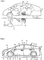
- Vehicle main body 70 includes: a rear fender 85L disposed at a rear side relative to boarding opening 82L in the traveling direction; and a rear bumper 87 disposed at a rear side relative to rear fender 85L in the travelling direction.
- rear surface 74 of electrically powered vehicle 10 is a surface that can be seen when electrically powered vehicle 10 is viewed from a position away from electrically powered vehicle 10 backwardly in the traveling direction.
- upper surface 75 of electrically powered vehicle 10 is mainly defined by engine roof 88, roof 66, and upper surface portion 67a of hatch 67.
- bottom surface 76 of electrically powered vehicle 10 is a surface that can be seen when electrically powered vehicle 10 is viewed from a position away downwardly in the direction perpendicular to the ground in a state such that the tires of electrically powered vehicle 10 are in contact with the ground.
- Power reception device 11 is provided at the bottom surface 76 side of electrically powered vehicle 10.
- electrically powered vehicle 10 may include: side members 47 arranged in the width direction of the vehicle; and a plurality of cross members provided to connect side members 47 to each other, power reception device 11 being suspended from side members 47 and the cross members.
- electrically powered vehicle 10 includes a floor panel 49, and power reception device 11 may be fixed to this floor panel 49.
- power reception device 11 is disposed at the bottom surface 76 side
- power reception device 11 does not need to be necessarily provided at a position that can be visually seen when electrically powered vehicle 10 is viewed from below electrically powered vehicle 10.
- refueling portion 77 is provided at rear fender 85L and charging portion 78 is provided at rear fender 85R.
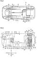
- Power reception unit 20 is provided in bottom surface 76 at a portion below luggage compartment 68.
- Fuel tank 79 includes: a main body portion 79a provided at the front side of electrically powered vehicle 10 relative to power reception unit 20; and an auxiliary tank portion 79b extending from main body portion 79a into between rear wheel 19R and power reception unit 20.
- Rectifier 13 is disposed at the front side of electrically powered vehicle 10 relative to power reception unit 20.
- Converter 14 is disposed at the front side of electrically powered vehicle 10 relative to power reception unit 20.
- Battery 15 is provided at the front side of electrically powered vehicle 10 relative to power reception unit 20.
- Power control unit 16 and motor unit 17 are also disposed at the front side relative to power reception unit 20.
- Power reception unit 20 and rectifier 13 are connected to each other by an interconnection 19a.
- Rectifier 13 and converter 14 are connected to each other by an interconnection 19b.
- Converter 14 and battery 15 are connected to each other by an interconnection 19c.
- battery 15 and power control unit 16 are connected to each other by an interconnection 19d, and power control unit 16 and motor unit 17 are connected to each other by an interconnection 19e.
- Camera 33 is provided in rear surface 74 at the rear portion of electrically powered vehicle 10 relative to power reception unit 20.
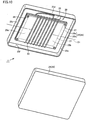
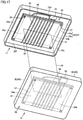
- Fig. 9 is a cross sectional view showing power reception device 11, and Fig. 10 is an exploded perspective view of power reception device 11.
- power reception device 11 includes power reception unit 20 and a case 24 having power reception unit 20 accommodated therein.
- Shield 25 includes: a top plate portion 25a; and a circumferential wall portion 25b formed to extend downwardly from the circumferential edge portion of top plate portion 25a.
- Circumferential wall portion 25b includes a plurality of wall portions 25c to 25f, and the plurality of wall portions 25c to 25f are connected to one another to form annular circumferential wall portion 25b.
- Wall portion 25c and wall portion 25e are arranged in a direction in which winding axis O1 of secondary coil 22 extends, whereas wall portion 25d and wall portion 25f are arranged in a direction perpendicular to winding axis O1 of secondary coil 22.
- the shape of shield 25 is not limited to such a shape and various types of shapes can be employed such as a polygonal shape, a circular shape, and an oval shape.
- Power reception unit 20 includes: a ferrite core 21 formed to have a plate-like shape; a fixation member 27 that sandwiches ferrite core 21 from the upper and lower sides; a secondary coil 22 wound around fixation member 27; and a capacitor 23 connected to secondary coil 22.
- Ferrite core 21 includes a protrusion portion 29a and a protrusion portion 29b, each of which protrudes from the inside of secondary coil 22 in the direction in which winding axis O1 extends.
- Protrusion portion 29a protrudes from one end side of secondary coil 22, whereas protrusion portion 29b protrudes from the other end side of secondary coil 22.
- ferrite core 21 is formed to be longer than the length of secondary coil 22 in the direction in which winding axis O1 extends.
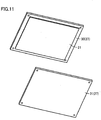
- Fig. 11 is an exploded perspective view showing fixation member 27 and ferrite core 21.
- fixation member 27 includes: an insulation piece 30 disposed at the upper surface side of ferrite core 21; and an insulation piece 31 disposed at the lower surface side of ferrite core 21.
- ferrite core 21 is formed to have a substantially rectangular solid shape, and ferrite core 21 includes: an upper surface 37; a bottom surface 38 opposite to upper surface 37 in the thickness direction; side surfaces 39 and 40 arranged in the short direction; and end surfaces 41 and 42 arranged in the longitudinal direction. It is to be noted that ferrite core 21 may be constructed of a plurality of divided ferrite pieces.
- Secondary coil 22 includes: long side portions 43 disposed on upper surface 37; short side portions 44 extending downwardly from the end portions of long side portions 43 and disposed on side surface 39; long side portions 45 connected to short side portions 44 and disposed on bottom surface 38; and short side portions 46 connected to the end portions of long side portions 45 and disposed on side surface 40.
- One turn of the coil wire around the circumferential surfaces of ferrite core 21 is provided by one long side portion 43, one short side portion 44, one long side portion 45, and one short side portion 46.
- One opening edge portion 69a of secondary coil 22 is formed by first end portion 35, long side portion 43 having first end portion 35, short side portion 44 connected to this long side portion 43, long side portion 45 connected to this short side portion 44, and short side portion 46 connected to this long side portion 45.
- Fig. 13 is a plan view of secondary coil 22 when viewed in plan. As shown in Fig. 13 , the plurality of short side portions 46 are arranged in the direction in which winding axis O1 extends, and the plurality of short side portions 44 are arranged in a similar manner in the direction in which winding axis O1 extends.
- Short side portion 44 and short side portion 46 are disposed on the same imaginary horizontal plane, and short side portion 44 and short side portion 46 face each other with winding axis O1 therebetween.
- secondary coil 22 is formed to have a quadrangular shape when viewed from the front surface, but various types of shapes can be employed for the shape of the coil, such as an elliptical shape, an oval shape, and a polygon shape.
- Fig. 14 is a perspective view showing coil 200 as a model.
- Coil 200 is formed by curving coil wire 201 to surround winding axis O.
- Coil 200 is formed by winding coil wire 201 for a plurality of times. From end portion 202 to end portion 203 of coil 200, coil 200 is divided into minute portions dp each having a minute length dL.
- Fig. 15 is a side view showing coil 200 divided into the plurality of minute portions dp
- Fig. 16 is a front view showing coil 200 divided into the plurality of minute portions dp.
- winding axis O is derived by approximation such that it passes through curvature center point OP of each minute portion dp and a vicinity of curvature center point OP.
- various types of approximation methods such as linear approximation, logarithm approximation, and polynomial approximation can be used to derive winding axis O, which is an imaginary line, from each curvature center point OP.
- coil 200 shown in Fig. 14 has an equal pitch, and coil 200 has a winding diameter constant from end portion 202 to end portion 203. Accordingly, curvature center points OP of minute portions dp are arranged in one straight line, so that winding axis O is a straight line. Likewise, also in secondary coil 22 according to the present embodiment shown in Fig. 12 and Fig. 13 , the winding axis is a straight line.
- winding axis O1 is an imaginary straight line passing through center points P1, P2 of the openings surrounded by opening edge portions 69a, 69b.
- the "region disposed in the direction different from the direction in which the winding axis extends from the coil” is a region disposed in a direction different from the direction in which winding axis O1 extends from center points P1, P2.
- the direction extending from center point P1 to region R0 is the direction different from the direction in which winding axis O1 extends from center point P1.
- region R0 is included in the "region disposed in the direction different from the direction in which the winding axis extends from the coil". It is to be noted that region R0 shown in Fig.
- the region disposed in the direction different from the direction in which the winding axis extends from the coil may be a region satisfying the above-described condition.
- Fig. 17 is a perspective view showing a state in which power reception unit 20 and power transmission unit 56 are disposed to face each other. It is to be noted that in Fig. 17 , cover portion 26 provided in power reception device 11 is not shown in the figure.
- Case 60 includes: a shield 62 made of a metal material such as copper; and a cover member 63 made of a resin and provided on shield 62.
- Shield 62 includes a bottom surface portion, and a circumferential wall portion formed to have an annular shape rising upwardly from the outer circumferential edge of the bottom surface portion, and the circumferential wall portion has an upper end portion extending in an annular manner to provide an opening that opens upwardly.
- Cover member 63 is formed to close the opening formed by the upper end portion of the circumferential wall portion of shield 62.
- Ferrite core 57 includes an protrusion portion 64a and an protrusion portion 64b, each of which protrudes in the direction in which the winding axis of primary coil 58 extends.
- Protrusion portion 64a is formed to protrude from one end side of primary coil 58, whereas protrusion portion 64b protrudes from the other end side of primary coil 58.
- Fixation member 61 includes: an insulation piece disposed at the upper surface side of ferrite core 57; and an insulation piece disposed at the lower surface side of ferrite core 57. Ferrite core 57 is sandwiched between these two insulation pieces. The two insulation pieces are fixed to each other by a fastening member such as a bolt and a nut, thereby sandwiching ferrite core 57 between the two insulation pieces.
- Primary coil 58 is wound around the outer circumferential surface of fixation member 61.
- a difference between the natural frequency of power transmission unit 56 and the natural frequency of power reception unit 20 is 10% or less of the natural frequency of power reception unit 20 or power transmission unit 56.
- the expression “natural frequency of power transmission unit 56" is intended to mean an oscillation frequency at which the electric circuit formed by the inductance of primary coil 58 and the capacitance of primary coil 58 freely oscillates.
- the expression “natural frequency of power transmission unit 56” is intended to mean an oscillation frequency at which the electric circuit formed by the capacitances of primary coil 58 and capacitor 59 and the inductance of primary coil 58 freely oscillates.
- the natural frequency when the damping force and the electric resistance are set at zero or substantially zero is also called “resonance frequency of power transmission unit 56".
- Fig. 18 shows a simulation model of the power transfer system.
- the power transfer system includes a power transmission device 90 and a power reception device 91.
- Power transmission device 90 includes a coil 92 (electromagnetic induction coil) and a power transmission unit 93.
- Power transmission unit 93 includes a coil 94 (resonance coil) and a capacitor 95 provided in coil 94.
- Power reception device 91 includes a power reception unit 96 and a coil 97 (electromagnetic induction coil).
- Power reception unit 96 includes a coil 99 and a capacitor 98 connected to coil 99 (resonance coil).
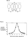
- Fig. 19 shows a relation between the power transfer efficiency and the deviation in natural frequency between power transmission unit 93 and power reception unit 96 when only inductance Lt is changed with inductance Lr and capacitances C1, C2 being fixed.
- a relative positional relation between coil 94 and coil 99 is fixed, and the frequency of current supplied to power transmission unit 93 is constant.
- Deviation in Natural Frequency f 1 ⁇ f 2 / f 2 ⁇ 100 %
- the power transfer efficiency can be improved by setting the natural frequency of each of the power transmission unit and the power reception unit such that the absolute value (difference in natural frequency) of the deviation (%) in natural frequency falls within a range of 10% or less of the natural frequency of power reception unit 96.
- the power transfer efficiency can be more improved by setting the natural frequency of each of the power transmission unit and the power reception unit such that the absolute value of the deviation (%) in natural frequency falls within a range of 5% or less of the natural frequency of power reception unit 96.
- electromagnetic field analysis software JMAG® provided by JSOL Corporation is employed as simulation software.
- primary coil 58 is supplied with AC power from high-frequency power driver 54. On this occasion, the electric power is supplied such that the alternating current flowing in primary coil 58 has a specific frequency.
- Secondary coil 22 is disposed in a predetermined range from primary coil 58 and receives electric power from the electromagnetic field formed around primary coil 58.
- helical coils are employed for secondary coil 22 and primary coil 58. Accordingly, magnetic field and electric field, which oscillate at the specific frequency, are formed around primary coil 58 and secondary coil 22 receives electric power mainly from the magnetic field.
- the magnetic field formed around primary coil 58 and having the specific frequency is typically relevant to the power transfer efficiency and the frequency of current supplied to primary coil 58.
- the power transfer efficiency when transferring electric power from primary coil 58 to secondary coil 22 is changed depending on various factors such as a distance between primary coil 58 and secondary coil 22.
- the natural frequencies (resonance frequencies) of power transmission unit 56 and power reception unit 20 are assumed as natural frequency f0
- the frequency of current supplied to primary coil 58 is assumed as frequency f3
- the air gap between secondary coil 22 and primary coil 58 is assumed as air gap AG.
- Fig. 20 is a graph indicating a relation between the power transfer efficiency and frequency f3 of current supplied to primary coil 58 when air gap AG is changed with natural frequency f0 being fixed.
- An efficiency curve L1 schematically represents a relation between the power transfer efficiency when air gap AG is small and frequency f3 of the current supplied to primary coil 58.
- efficiency curve L1 when air gap AG is small, peaks of the power transfer efficiency appear at frequencies f4, f5 (f4 ⁇ f5).
- efficiency curve L2 when air gap AG is made larger, the two peaks at which the power transfer efficiency becomes high are changed to come closer to each other.
- an efficiency curve L2 when air gap AG is made larger than a predetermined distance, one peak of the power transfer efficiency appears.
- the peak of the power transfer efficiency appears when the current supplied to primary coil 58 has a frequency f6.
- efficiency curve L3 When air gap AG is made further larger from the state of efficiency curve L2, the peak of the power transfer efficiency becomes smaller as indicated by an efficiency curve L3.
- the first technique is to change a characteristic of the power transfer efficiency between power transmission unit 56 and power reception unit 20 by changing the capacitances of capacitor 59 and capacitor 23 in accordance with air gap AG with the frequency of the current supplied to primary coil 58 shown in Fig. 1 being constant. Specifically, with the frequency of the current supplied to primary coil 58 being constant, the capacitances of capacitor 59 and capacitor 23 are adjusted to attain a peak of the power transfer efficiency. In this technique, irrespective of the size of air gap AG, the frequency of the current flowing in primary coil 58 and secondary coil 22 is constant. It is to be noted that as the technique of changing the characteristic of the power transfer efficiency, the following techniques can be also employed: a technique of using a matching device provided between power transmission device 50 and high-frequency power driver 54; and a technique of using converter 14.
- a second technique is a technique of adjusting, based on the size of air gap AG, the frequency of the current supplied to primary coil 58.
- the frequency characteristic corresponds to efficiency curve L1 or L3.
- the frequency characteristic corresponds to efficiency curve L2 or L3
- primary coil 58 is supplied with current having frequency f6. In this case, the frequency of the current flowing in each of primary coil 58 and secondary coil 22 is changed in accordance with the size of air gap AG.
- the frequency of the current flowing in primary coil 58 becomes a fixed, constant frequency.
- the frequency thereof flowing in primary coil 58 becomes a frequency appropriately changed according to air gap AG.
- primary coil 58 is supplied with current having a specific frequency set to attain high power transfer efficiency. Because the current having the specific frequency flows in primary coil 58, a magnetic field (electromagnetic field), which oscillates at the specific frequency, is formed around primary coil 58.
- Power reception unit 20 receives electric power from power transmission unit 56 via the magnetic field formed between power reception unit 20 and power transmission unit 56 and oscillating at the specific frequency. Therefore, "the magnetic field oscillating at the specific frequency” is not necessarily a magnetic field having a fixed frequency.
- the frequency of the current supplied to primary coil 58 is set based on air gap AG, but the power transfer efficiency is also changed according to other factors such as a deviation in the horizontal direction between primary coil 58 and secondary coil 22, so that the frequency of the current supplied to primary coil 58 may be adjusted based on the other factors.
- Fig. 21 shows a relation between a distance from the electric current source or magnetic current source and the strength of the electromagnetic field.
- the electromagnetic field is constituted of three components.
- a curve k1 represents a component in inverse proportion to the distance from the wave source, and is referred to as "radiation electromagnetic field”.
- a curve k2 represents a component in inverse proportion to the square of the distance from the wave source, and is referred to as "induction electromagnetic field".
- a curve k3 represents a component in inverse proportion to the cube of the distance from the wave source, and is referred to as "electrostatic magnetic field". Assuming that the wavelength of the electromagnetic field is represented by " ⁇ ”, ⁇ /2 ⁇ represents a distance in which the strengths of the "radiation electromagnetic field”, the “induction electromagnetic field”, and the “electrostatic magnetic field” are substantially the same.
- the “electrostatic magnetic field” is a region in which the strength of the electromagnetic wave is abruptly decreased as the distance is farther away from the wave source.
- the near field evanescent field
- this "electrostatic magnetic field” is dominant, is utilized for transfer of energy (electric power).
- the energy (electric power) is transferred from power transmission unit 56 to the other side, i.e., power reception unit 20.
- This "electrostatic magnetic field” does not propagate energy to a distant place.
- the resonance method allows for electric power transmission with less energy loss as compared with the electromagnetic wave in which the "radiation electromagnetic field” propagating energy to a distance place is utilized to transfer energy (electric power).
- a coupling coefficient ⁇ between the power transmission unit and the power reception unit is about 0.3 or less, preferably, 0.1 or less, for example. Coupling coefficient ⁇ may also fall within a range of about 0.1 to about 0.3. Coupling coefficient ⁇ is not limited to such a value, and various values to attain excellent electric power transfer can be employed.
- electromagnetic field resonance coupling is intended to indicate coupling including any of the “magnetic resonance coupling”, the “magnetic field resonance coupling”, and the “electric field resonance coupling”.
- Each of primary coil 58 of power transmission unit 56 and secondary coil 22 of power reception unit 20 as described in the present specification employs an antenna having a coil shape, so that power transmission unit 56 and power reception unit 20 are coupled to each other mainly by a magnetic field.
- power transmission unit 56 and power reception unit 20 are coupled to each other by means of the "magnetic resonance coupling” or the “magnetic field resonance coupling”.
- an antenna such as a meander line antenna can be employed as each of primary coil 58 and secondary coil 22, for example.
- power transmission unit 56 and power reception unit 20 are coupled to each other mainly through electric field.
- power transmission unit 56 and power reception unit 20 are coupled to each other by means of the "electric field resonance coupling".
- region R1 schematically represents a region in which magnetic field (electromagnetic field) takes place during transfer of electric power.
- the magnetic field (electromagnetic field) during the transfer of electric power is distributed to have strength higher in the direction in which winding axis O1 extends from center points P1, P2 of secondary coil 22, than in the direction different from the direction in which winding axis O1 extends from center points P1, P2.
- Imaginary line L6 is an imaginary line extending from a connection portion of short side portion 44 and long side portion 45 in the direction in which winding axis O1 extends.
- Imaginary line L7 is an imaginary line L7 extending from a connection portion of long side portion 45 and short side portion 46 in the direction in which winding axis O1 extends.
- an adjacent region R3 is also a region surrounded by: an imaginary line extending from second end portion 36 in the direction in which winding axis O1 extends; an imaginary line extending from the connection portion of long side portion 43 and short side portion 44 in the direction in which winding axis O1 extends; and an imaginary line extending from the connection portion of short side portion 44 and long side portion 45 in the direction in which winding axis O1 extends.
- secondary coil 22 is disposed such that winding axis O1 extends in width direction D2 of electrically powered vehicle 10. It is to be noted that in the present embodiment, secondary coil 22 is disposed such that winding axis O1 is directed in the horizontal direction.
- the expression “winding axis O1 is directed in the horizontal direction” includes both a case where winding axis O1 extends completely in the horizontal direction and a case where winding axis O1 is directed substantially in the horizontal direction.
- the expression “winding axis O1 is directed substantially in the horizontal direction” is intended to mean that a crossing angle between the imaginary horizontal plane and winding axis O1 is 10° or less, for example.
- winding axis O1 is directed in the horizontal direction
- winding axis O1 is directed in width direction D2 as in the example in Fig. 8 and includes a case where winding axis O1 is directed in front-rear direction D1 of electrically powered vehicle 10.
- Rectifier 13, converter 14, battery 15, power control unit 16, and motor unit 17 are disposed in a region in the direction different from the direction in which winding axis O1 extends from secondary coil 22. Accordingly, during transfer of electric power, an electromagnetic field having high strength can be suppressed from reaching rectifier 13, converter 14, battery 15, power control unit 16, and motor unit 17.
- Secondary coil 22 is disposed such that winding axis O1 extends in width direction D2 of electrically powered vehicle 10, so that adjacent region R2 and adjacent region R3 also extend in width direction D2.
- Adjacent region R2 extends from secondary coil 22 toward left side surface 71.
- Adjacent region R3 extends from secondary coil 22 toward right side surface 72.
- adjacent region R2 and adjacent region R3 are regions in which an electromagnetic field having high strength is likely to be formed during transfer of electric power.
- rectifier 13, converter 14, battery 15, and power control unit 16 and motor unit 17 are disposed in the regions different from adjacent region R2 and adjacent region R3.
- rectifier 13, converter 14, battery 15, power control unit 16, and motor unit 17 are provided in the regions not only disposed in the direction different from the direction in which winding axis O1 extends from secondary coil 22 but also away from adjacent region R2 and adjacent region R3.
- rectifier 13 in the region different from adjacent regions R2, R3, electric elements can be suppressed from being affected.
- converter 14 which includes a plurality of electronic components such as a transistor and a diode, in the region different from adjacent regions R2, R3, converter 14 can be suppressed from being affected by the electromagnetic field.
- the electronic components includes: a passive element such as a diode, a transistor, a capacitor, a resistor, a coil, or a relay; and an active element including a plurality of passive elements.
- Battery 15 includes: a plurality of battery cells 15a; and an electronic component, such as a thermistor 15b, for measuring a temperature of battery cell 15a.
- an electronic component such as a thermistor 15b, for measuring a temperature of battery cell 15a.
- Each of the inverter and converter provided in power control unit 16 includes a plurality of diodes and a plurality of transistors, and is constructed of a plurality of electronic components. Because power control unit 16 is disposed in the region different from adjacent regions R2, R3, the above-described electronic components can be suppressed from being affected by the electromagnetic field.
- Motor unit 17 includes a rotating electrical machine and a photosensor 17a, for example.
- the rotating electrical machine includes a rotor rotatably provided and a stator disposed around the rotor.
- the stator includes a stator coil, and many magnetic fluxes flow between the rotor and the stator.
- Photosensor 17a is an electronic device that measures the rotation speed of the rotor, and photosensor 17a is constructed of a plurality of electronic components.
- motor unit 17 is disposed in the region different from adjacent regions R2, R3, the magnetic flux formed between the rotor and the stator can be suppressed from being greatly affected by the electromagnetic field formed around power reception unit 20, and photosensor 17a can be also suppressed from being affected by the electromagnetic field.
- Interconnections 19a to 19e connecting the electronic devices are disposed in regions different from adjacent regions R2, R3. Accordingly, disturbance can be suppressed from being added to current flowing in each of interconnections 19a to 19e.
- Camera 33 is disposed at the rear side of electrically powered vehicle 10 relative to secondary coil 22, adjacent region R2, and adjacent region R3. Accordingly, camera 33 can be suppressed from being affected by the electromagnetic field formed around secondary coil 22.
- electrically powered vehicle 10 includes an adjacent device at least having a portion disposed in adjacent region R2 or adjacent region R3.
- fuel tank 79 As the adjacent device, fuel tank 79, refueling portion 77, charging portion 78, and tool containing portion 101 are included. It is to be noted that tool containing portion 101 is a space for containing a jack, a repairing tool, and the like therein.
- the number of electronic components included in fuel tank 79 is less than the number of electronic components included in the electronic devices included in electric device module 100.
- the number of electronic components included in each of refueling portion 77, charging portion 78, and tool containing portion 101 is less than the number of electronic components included in each of the above-described electronic devices.
- Fig. 26 is a plan view schematically showing electrically powered vehicle 10 according to the second embodiment. As shown in Fig. 26 , power reception unit 20 is disposed between rear wheel 19R and rear wheel 19L.
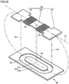
- Fig. 27 is a plan view showing power reception unit 20.
- Fig. 28 is a cross sectional view taken along a XXVIII-XXVIII line shown in Fig. 27 .
- power reception unit 20 includes a ferrite core 21, and a coil unit 120 provided on the lower surface of ferrite core 21.
- Ferrite core 21 is formed to have a rectangular shape and is disposed to be long in width direction D2 as shown in Fig. 26 .
- coil unit 120 includes a coil 121 and a coil 122 arranged side by side in the longitudinal direction of ferrite core 21.
- Coil 121 is formed by winding a litz wire (coil wire) around a winding axis 04 extending in the vertical direction, and the litz wire is wound in a plane extending along the lower surface of ferrite core 21.
- Coil 122 is formed by winding a litz wire (coil wire) around a winding axis 05 extending in the vertical direction, and the litz wire is wound in an imaginary plane passing through the lower surface of ferrite core 21.
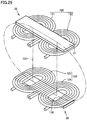
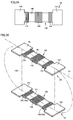
- Fig. 29 is a perspective view showing power reception unit 20 and power transmission unit 56. As shown in this Fig. 29 , power transmission unit 56 is formed in a manner similar to power reception unit 20.
- Power transmission unit 56 includes: a core ferrite core 126 formed to have a plate-like shape; and a coil unit 125 disposed on the upper surface of this core ferrite core 126.
- Core ferrite core 126 is also formed to have a rectangular shape.
- Coil unit 125 includes a coil 123 and a coil 124 arranged side by side in the longitudinal direction of core ferrite core 126.
- Coil 123 is formed by winding a litz wire (coil wire) to surround the winding axis, and the litz wire is wound in a plane passing through the upper surface of core ferrite core 126.
- Coil 124 is formed by winding a litz wire to surround the winding axis, and this litz wire is also wound in the plane passing through the upper surface of core ferrite core 126.
- Each of coil 123 and coil 124 is formed by winding a coil wire to form a hollow portion, and core ferrite core 126 is exposed through the hollow portions of coil 123 and coil 124.
- Magnetic path 130 passes through the hollow portion of coil 123, the air gap, the hollow portion of coil 121, the portion of ferrite core 21 exposed through the hollow portion of coil 121, and the portion of ferrite core 21 between coil 121 and coil 122. Further, magnetic path 130 passes through the portion of ferrite core 21 exposed through the hollow portion of coil 122, the hollow portion of coil 122, the air gap, and the hollow portion of coil 124. Further, magnetic path 130 passes through the portion of ferrite core 126 exposed through the hollow portion of coil 124, the portion of ferrite core 126 between coil 123 and coil 124, and the portion of ferrite core 126 exposed through the hollow portion of coil 123.
- a part of the magnetic flux may be emitted from the end portion of ferrite core 21 to outside, and then may reach the end portion of ferrite core 126 through the air gap.
- the electromagnetic field having high strength is distributed more widely in the direction in which coil 121 and coil 122 are arranged side by side than in a direction perpendicular to the direction in which coil 121 and coil 122 are arranged side by side.
- the electromagnetic field having high strength is less likely to be distributed in the direction crossing (orthogonal to) the direction in which coil 121 and coil 122 are arranged side by side.
- an aluminum plate may be employed instead of ferrite core 150.
- power reception unit 20 receives electric power from power transmission unit 56 of a type different from power reception unit 20.
- power transmission unit 56 includes a ferrite core 160 and a coil 163 provided in ferrite core 160.
- Ferrite core 160 includes: a base portion 162 having a plate-like shape and having a groove portion 164 formed at its central portion; and a stem portion 161 formed in groove portion 164.
- Coil 163 is disposed in groove portion 164 to surround stem portion 161.
- Magnetic path 165 passes through, for example, stem portion 161, the air gap, stem portion 146, the inside of coil 142, wide portion 145, the air gap, and base portion 162.
- the electromagnetic field having high strength is widely distributed in the direction in which winding axis O1 extends, in both the case where electric power is transferred between power reception unit 20 and power transmission unit 56 of the same type as power reception unit 20 and the case where electric power is transferred between power reception unit 20 and power transmission unit 56 of a type different from power reception unit 20.
- coil unit 141 is disposed such that winding axis O1 extends in width direction D2.
- the electromagnetic field having high strength is widely distributed in the direction in which winding axis O1 extends from secondary coil 22.
- the electromagnetic field having high strength is not widely distributed in the direction orthogonal to winding axis 01.
- the "first direction” corresponds to the "direction orthogonal to winding axis O1”
- the "second direction” corresponds to the "direction in which winding axis O1 extends”.
- Adjacent region R2 is a region extending in the direction in which winding axis O1 extends from coil 143.
- Adjacent region R3 is a region extending in the direction in which winding axis O1 extends from coil 142.
- the electromagnetic field having high strength is distributed in adjacent region R2 and adjacent region R3.
- rectifier 13, converter 14, battery 15, power control unit 16 and motor unit 17 are disposed at the front side of electrically powered vehicle 10 relative to adjacent region R2 and adjacent region R3.
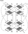
- Fig. 37 is a plan view schematically showing electrically powered vehicle 10 according to the fourth embodiment. As shown in Fig. 37 , power reception unit 20 is disposed between rear wheel 19L and rear wheel 19R.
- power reception unit 20 includes a ferrite core 170 and a coil unit 171 provided in ferrite core 170.
- Coil 184 and coil 182 are formed to surround a winding axis O1a, and coil 184 and coil 182 are disposed with a space therebetween in a direction in which winding axis O1a extends.
- Coil 181 and coil 183 are formed to surround a winding axis O1b, and coil 181 and coil 183 are disposed with a space therebetween in a direction in which winding axis O1b extends.
- winding axis O1a and winding axis O1b are orthogonal to each other in the example shown in Fig. 38 , but the intersecting angle between winding axis O1a and winding axis O1b may be an acute angle or an obtuse angle.
- a magnetic path 195 is formed between coil 184 and coil 187.
- Magnetic path 196 is formed between coil 181 and coil 188.
- Magnetic path 197 is formed between coil 182 and coil 189.
- Magnetic path 198 is formed between coil 183 and coil 190.
- the electromagnetic field having high strength is less likely to be distributed in the direction in which each of imaginary straight line 03 and imaginary straight line 04 extends.
- adjacent region R4 is a region extending in the direction in which winding axis O1a extends from coil 184.
- Adjacent region R5 is a region extending in the direction in which winding axis O1b extends from coil 181.
- Adjacent region R6 is a region extending in the direction in which winding axis O1a extends from coil 182.
- Adjacent region R7 is a region extending in the direction in which winding axis O1b extends from coil 183.
- rectifier 13, converter 14, battery 15, power control unit 16 and motor unit 17 are disposed at the front side of electrically powered vehicle 10 relative to adjacent regions R4, R5, R6, R7.
- Camera 33 is disposed at the rear side of electrically powered vehicle 10 to be separated away from each of adjacent regions R4, R5, R6, R7.
- the electronic device can be less affected by the electromagnetic field and a dead space can be effectively utilized.
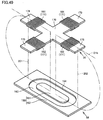
- Fig. 40 is a perspective view showing the transfer of electric power between power reception unit 20 and power transmission unit 56.
- power transmission unit 56 includes a ferrite core 160 and a coil 163.
- Base portion 162 is formed to have a plate-like shape and includes: a groove portion 164; and a stem portion 161 formed to project upwardly from the central portion of groove portion 164.
- Coil 163 is wound around stem portion 161.
- magnetic paths 201, 202 are formed between power reception unit 20 and power transmission unit 56.
- magnetic path 202 passes through stem portion 161, the air gap, the central portion of ferrite core 170, the inside of coil 181, the end portion of core piece 174, the air gap, and ferrite core 160.
- Magnetic path 202 passes through stem portion 161, the air gap, the central portion of ferrite core 170, the inside of coil 183, core piece 176, the air gap, and ferrite core 160.
- power reception unit 20 With the magnetic paths thus formed between power reception unit 20 and power transmission unit 56, large currents flow in coil 181 and coil 183. Accordingly, power reception unit 20 receives electric power from power transmission unit 56.
- the magnetic flux is widely distributed in the direction in which winding axis O1b extends.
- the electromagnetic field is widely distributed in the direction in which winding axis O1b extends.
- the electronic devices such as battery 15 are provided at positions away from adjacent region R4 and adjacent region R6, and a portion of tool containing portion 101 is disposed in adjacent region R4.
- rectifier 13, converter 14, battery 15, power control unit 16 and motor unit 17 are disposed in the regions disposed in the direction different from the direction in which winding axis O1 extends from secondary coil 22. Further, power reception unit 20 is disposed to be offset to the right side surface 72 side relative to the central portion of electrically powered vehicle 10 in width direction D2.
- rectifier 13, converter 14, battery 15, power control unit 16, and motor unit 17 are disposed to be offset to the left side surface 71 side relative to the central portion of electrically powered vehicle 10 in width direction D2. Accordingly, rectifier 13, converter 14, battery 15, power control unit 16, and motor unit 17 are disposed in regions different from adjacent regions R2, R3. Accordingly, also in electrically powered vehicle 10 according to the fifth embodiment, the electromagnetic field having high strength can be suppressed from reaching the electronic device.
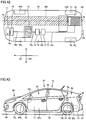
- Fig. 43 is a left side view showing electrically powered vehicle 10
- Fig. 44 is a perspective view schematically showing a layout of fuel tank 79, power reception unit 20, and battery 15.
- fuel tank 79 is provided at the front side relative to power reception unit 20, and battery 15 is disposed above power reception unit 20.
- battery 15 is disposed above power reception unit 20, the region in which battery 15 is positioned is disposed in the direction different from the direction in which winding axis O1 extends from secondary coil 22. Accordingly, an electromagnetic field having high strength can be suppressed from reaching battery 15.
- the region in which battery 15 is provided is different from adjacent regions R2, R3, so that the electromagnetic field having high strength can be suppressed from reaching battery 15.
- the present invention is not limited to the case where the electronic devices such as battery 15 and adjacent regions R2, R3 are separated from each other in the horizontal direction, and they may be separated in the height direction.
- battery 15 is disposed on floor panel 49, and power reception unit 20 is disposed at the lower surface side of floor panel 49. Accordingly, the electromagnetic field having high strength can be suppressed from reaching battery 15.
- an electromagnetic induction coil may be provided to transmit electric power, supplied from high-frequency power driver 54, to primary coil 58 through electromagnetic induction. Further, an electromagnetic induction coil may be disposed to receive electric power from secondary coil 22 through electromagnetic induction and supplies it to rectifier 13.
Landscapes
- Engineering & Computer Science (AREA)
- Power Engineering (AREA)
- Transportation (AREA)
- Mechanical Engineering (AREA)
- Computer Networks & Wireless Communication (AREA)
- Signal Processing (AREA)
- Sustainable Development (AREA)
- Sustainable Energy (AREA)
- Life Sciences & Earth Sciences (AREA)
- Chemical & Material Sciences (AREA)
- Combustion & Propulsion (AREA)
- Electric Propulsion And Braking For Vehicles (AREA)
- Current-Collector Devices For Electrically Propelled Vehicles (AREA)
- Charge And Discharge Circuits For Batteries Or The Like (AREA)
Claims (10)
- Véhicule comprenant:une unité de réception d'énergie (20) qui reçoit une énergie électrique sans contact depuis une unité de transmission d'énergie fournie extérieurement;un dispositif électronique ; etune première roue et une seconde roue agencées dans le sens de la largeur du véhicule,ladite unité de réception d'énergie (20) incluant une bobine (22) formée pour entourer un axe d'enroulement (01),une région dans laquelle ledit dispositif électronique est disposé en étant positionné dans une direction différente d'une direction dans laquelle ledit axe d'enroulement s'étend depuis ladite bobine ;caractérisé en ce que la bobine (22) est enroulée autour d'un noyau présentant une forme de plaque et disposée de telle sorte que l'axe d'enroulement (01) s'étende dans un sens horizontal, etladite unité de réception d'énergie est disposée entre ladite première roue et ladite seconde roue.
- Véhicule selon la revendication 1, dans lequel
une ouverture est formée au niveau d'une partie d'extrémité de ladite bobine, et
en supposant qu'une région s'étendant dans la direction dans laquelle ledit axe d'enroulement (01) s'étend depuis l'ouverture de ladite bobine (22) est une région adjacente (R2, R3), ledit dispositif électronique est disposé dans une région différente de ladite région adjacente (R2, R3). - Véhicule selon la revendication 1, dans lequel ledit dispositif électronique est l'un parmi une batterie (15) en mesure de stocker une énergie électrique, une PCU (unité de commande de puissance) reliée à ladite batterie (15) et une machine électrique tournante reliée à ladite PCU.
- Véhicule selon la revendication 1, dans lequel
ladite bobine (22) est disposée de telle sorte que ledit axe d'enroulement (01) s'étende dans un sens de la largeur dudit véhicule, et
ledit dispositif électronique est disposé sur un côté avant ou un côté arrière dudit véhicule par rapport à ladite bobine (22). - Véhicule selon la revendication 2, comprenant en outre un dispositif adjacent au moins présentant une partie disposée dans ladite région adjacente (R2, R3) lorsque vu du dessus du véhicule.
- Véhicule selon la revendication 5, dans lequel
ledit dispositif électronique inclut une batterie (15) en mesure de stocker une énergie électrique, et
ledit dispositif adjacent présente l'un parmi une partie d'accumulation, une première partie de liaison et une seconde partie de liaison, ladite partie d'accumulation étant en mesure d'accumuler une énergie autre qu'une énergie électrique, ladite première partie de liaison étant reliée à ladite partie d'accumulation, une unité d'alimentation fournissant ladite énergie étant reliée à la première partie de liaison, ladite seconde partie de liaison étant reliée à ladite batterie (15), une unité d'approvisionnement en énergie fournissant une énergie électrique étant reliée à ladite seconde partie de liaison. - Véhicule selon la revendication 2, dans lequel
ledit axe d'enroulement (01) inclut un premier axe d'enroulement et un second axe d'enroulement différant dudit premier axe d'enroulement par la direction,
ladite bobine inclut une première bobine et une seconde bobine, ladite première bobine étant formée pour entourer le premier axe d'enroulement, ladite seconde bobine étant formée pour entourer le second axe d'enroulement, et
ladite région adjacente (R2, R3) inclut une première région adjacente et une seconde région adjacente, ladite première région adjacente s'étendant dans une direction dans laquelle ledit second axe d'enroulement s'étend depuis ladite première bobine, ladite seconde région adjacente s'étendant en même temps que ledit second axe d'enroulement s'étend depuis ladite seconde bobine. - Véhicule selon la revendication 1, dans lequel une différence de fréquence propre entre ladite unité de transmission d'énergie et ladite unité de réception d'énergie (20) est égale ou inférieure à 10 % de la fréquence propre de ladite unité de réception d'énergie (20).
- Véhicule selon la revendication 1, dans lequel un facteur de couplage entre ladite unité de réception d'énergie (20) et ladite unité de transmission d'énergie est égal ou inférieur à 0,1.
- Véhicule selon la revendication 1, dans lequel ladite unité de réception d'énergie (20) reçoit une énergie électrique depuis ladite unité de transmission d'énergie à travers au moins l'un parmi un champ magnétique et un champ électrique, ledit champ magnétique étant formé entre ladite unité de réception d'énergie (20) et ladite unité de transmission d'énergie et oscillant à une fréquence spécifique, ledit champ électrique étant formé entre ladite unité de réception d'énergie (20) et ladite unité de transmission d'énergie et oscillant à la fréquence spécifique.
Priority Applications (1)
| Application Number | Priority Date | Filing Date | Title |
|---|---|---|---|
| EP17185998.6A EP3269585B1 (fr) | 2012-05-09 | 2012-05-09 | Véhicule comprenant unité de réception d'énergie sans contact |
Applications Claiming Priority (1)
| Application Number | Priority Date | Filing Date | Title |
|---|---|---|---|
| PCT/JP2012/061831 WO2013168242A1 (fr) | 2012-05-09 | 2012-05-09 | Véhicule |
Related Child Applications (2)
| Application Number | Title | Priority Date | Filing Date |
|---|---|---|---|
| EP17185998.6A Division EP3269585B1 (fr) | 2012-05-09 | 2012-05-09 | Véhicule comprenant unité de réception d'énergie sans contact |
| EP17185998.6A Division-Into EP3269585B1 (fr) | 2012-05-09 | 2012-05-09 | Véhicule comprenant unité de réception d'énergie sans contact |
Publications (3)
| Publication Number | Publication Date |
|---|---|
| EP2848453A1 EP2848453A1 (fr) | 2015-03-18 |
| EP2848453A4 EP2848453A4 (fr) | 2015-11-18 |
| EP2848453B1 true EP2848453B1 (fr) | 2017-10-11 |
Family
ID=49550327
Family Applications (2)
| Application Number | Title | Priority Date | Filing Date |
|---|---|---|---|
| EP12876151.7A Active EP2848453B1 (fr) | 2012-05-09 | 2012-05-09 | Véhicule comprenant bobine de réception d'énergie |
| EP17185998.6A Active EP3269585B1 (fr) | 2012-05-09 | 2012-05-09 | Véhicule comprenant unité de réception d'énergie sans contact |
Family Applications After (1)
| Application Number | Title | Priority Date | Filing Date |
|---|---|---|---|
| EP17185998.6A Active EP3269585B1 (fr) | 2012-05-09 | 2012-05-09 | Véhicule comprenant unité de réception d'énergie sans contact |
Country Status (6)
| Country | Link |
|---|---|
| US (1) | US10286794B2 (fr) |
| EP (2) | EP2848453B1 (fr) |
| JP (1) | JP5846302B2 (fr) |
| KR (1) | KR101750149B1 (fr) |
| CN (1) | CN104884295B (fr) |
| WO (1) | WO2013168242A1 (fr) |
Families Citing this family (21)
| Publication number | Priority date | Publication date | Assignee | Title |
|---|---|---|---|---|
| CN104335450A (zh) * | 2012-05-09 | 2015-02-04 | 丰田自动车株式会社 | 能够以非接触的方式接受电力的车辆 |
| JP5979227B2 (ja) | 2012-05-09 | 2016-08-24 | トヨタ自動車株式会社 | 車両 |
| JP6043462B2 (ja) * | 2012-09-27 | 2016-12-14 | Ihi運搬機械株式会社 | 車両給電装置 |
| JP6063719B2 (ja) * | 2012-11-19 | 2017-01-18 | 株式会社東芝 | 無線電力伝送装置 |
| JP5286445B1 (ja) * | 2012-12-28 | 2013-09-11 | 株式会社日立パワーソリューションズ | 電動式移動体の無線給電装置 |
| JP6111139B2 (ja) * | 2013-05-21 | 2017-04-05 | 株式会社テクノバ | 双方向非接触給電装置 |
| DE102013225241A1 (de) | 2013-12-09 | 2015-06-11 | Bayerische Motoren Werke Aktiengesellschaft | Feldabschirmung bei induktivem Laden |
| JP6107715B2 (ja) * | 2014-03-19 | 2017-04-05 | 株式会社ダイフク | 給電パッドとその給電パッドを用いたフォークリフトの非接触充電システム、および、受電パッドとその受電パッドを用いた非接触給電設備の2次側受電回路 |
| EP3528267B1 (fr) * | 2014-03-24 | 2021-01-27 | Apple Inc. | Protection magnétique dans un transfert de puissance inductive |
| US9806555B2 (en) * | 2014-07-07 | 2017-10-31 | Verizon Patent And Licensing Inc. | Peer to peer self-optimizing resonant inductive charger |
| CN111976507B (zh) * | 2014-09-02 | 2021-12-24 | 葛炽昌 | 具有交换电池组的电动车 |
| EP3103674B1 (fr) * | 2015-06-12 | 2021-08-18 | Brusa Elektronik AG | Systeme de determination de position, procede de determination de position et systeme inductif de transfert d'energie a l'aide d'un systeme de determination de position |
| US10093195B2 (en) | 2015-11-13 | 2018-10-09 | Nio Usa, Inc. | Integrated vehicle charging panel system and method of use |
| US10124690B2 (en) | 2015-11-13 | 2018-11-13 | Nio Usa, Inc. | Electric vehicle charging device positioning and method of use |
| US10059213B2 (en) | 2015-11-13 | 2018-08-28 | Nio Usa, Inc. | Charging devices within wheel portions |
| US10336194B2 (en) | 2015-11-13 | 2019-07-02 | Nio Usa, Inc. | Electric vehicle charging device alignment and method of use |
| US9944192B2 (en) * | 2015-11-13 | 2018-04-17 | Nio Usa, Inc. | Electric vehicle charging station system and method of use |
| US10756572B2 (en) | 2016-05-20 | 2020-08-25 | Lear Corporation | Wireless charging pad having coolant assembly |
| JP6460068B2 (ja) | 2016-09-05 | 2019-01-30 | トヨタ自動車株式会社 | 車両 |
| US10245963B2 (en) * | 2016-12-05 | 2019-04-02 | Lear Corporation | Air cooled wireless charging pad |
| DE102020215074A1 (de) * | 2020-11-30 | 2022-06-02 | Mahle International Gmbh | Elektromagnetische Induktionsladeeinrichtung |
Family Cites Families (28)
| Publication number | Priority date | Publication date | Assignee | Title |
|---|---|---|---|---|
| JP4220946B2 (ja) * | 2004-08-11 | 2009-02-04 | 三菱重工業株式会社 | 電気車両、架線レス交通システム及び架線レス交通システムの制御方法 |
| US7825543B2 (en) | 2005-07-12 | 2010-11-02 | Massachusetts Institute Of Technology | Wireless energy transfer |
| CN102983639B (zh) | 2005-07-12 | 2016-01-27 | 麻省理工学院 | 无线非辐射能量传递 |
| EP2078330A2 (fr) * | 2006-10-25 | 2009-07-15 | Laszlo Farkas | Systeme de transfert d'energie resonant sans fil a haute puissance |
| EP2130287A1 (fr) | 2007-03-27 | 2009-12-09 | Massachusetts Institute of Technology | Transfert d'énergie sans fil |
| JP4772744B2 (ja) * | 2007-05-17 | 2011-09-14 | 昭和飛行機工業株式会社 | 非接触給電装置用の信号伝送コイル通信装置 |
| US8030888B2 (en) * | 2007-08-13 | 2011-10-04 | Pandya Ravi A | Wireless charging system for vehicles |
| JP5227323B2 (ja) * | 2007-08-24 | 2013-07-03 | トヨタ自動車株式会社 | 車両およびハイブリッド車両 |
| JP5381011B2 (ja) | 2008-10-20 | 2014-01-08 | トヨタ自動車株式会社 | 給電システム |
| EP2360049B1 (fr) * | 2008-11-21 | 2016-04-20 | Toyota Jidosha Kabushiki Kaisha | Véhicule électrique |
| JP5467569B2 (ja) | 2009-01-21 | 2014-04-09 | 国立大学法人埼玉大学 | 非接触給電装置 |
| JP2010183812A (ja) * | 2009-02-09 | 2010-08-19 | Toyota Industries Corp | 共鳴型非接触充電システム |
| JP2010246348A (ja) | 2009-04-09 | 2010-10-28 | Fujitsu Ten Ltd | 受電装置、及び送電装置 |
| JP5354539B2 (ja) | 2009-08-25 | 2013-11-27 | 国立大学法人埼玉大学 | 非接触給電装置 |
| EP2459410B1 (fr) | 2009-10-14 | 2015-03-04 | Panasonic Corporation | Machine électrique et système d'alimentation électrique comportant un bloc-batterie |
| JP5506327B2 (ja) | 2009-10-27 | 2014-05-28 | 株式会社ヘッズ | 非接触電力供給装置 |
| EP2543535A4 (fr) * | 2010-03-04 | 2014-05-14 | Honda Motor Co Ltd | Véhicule électrique |
| JP5051257B2 (ja) | 2010-03-16 | 2012-10-17 | トヨタ自動車株式会社 | 車両 |
| JP5139469B2 (ja) * | 2010-04-27 | 2013-02-06 | 株式会社日本自動車部品総合研究所 | コイルユニットおよび非接触給電システム |
| DE102010027640B4 (de) | 2010-07-19 | 2023-10-05 | Sew-Eurodrive Gmbh & Co Kg | Elektrobeladungssystem und Verfahren zum berührungslosen Beladen einer Batterie in einer mobilen Einheit |
| JP5530848B2 (ja) | 2010-07-28 | 2014-06-25 | トヨタ自動車株式会社 | コイルユニット、非接触電力送電装置、非接触電力受電装置、車両および非接触電力給電システム |
| US9552920B2 (en) * | 2010-07-28 | 2017-01-24 | General Electric Company | Contactless power transfer system |
| DE102010044999A1 (de) * | 2010-09-10 | 2012-03-15 | Li-Tec Battery Gmbh | Anordnung und Verfahren zum Laden einer Fahrzeugbatterie |
| JP5730587B2 (ja) * | 2011-01-05 | 2015-06-10 | 昭和飛行機工業株式会社 | 磁界共鳴方式の非接触給電装置 |
| JP5658592B2 (ja) * | 2011-02-21 | 2015-01-28 | 国立大学法人埼玉大学 | 移動体用非接触給電装置 |
| WO2013168241A1 (fr) | 2012-05-09 | 2013-11-14 | トヨタ自動車株式会社 | Véhicule |
| JP5979227B2 (ja) | 2012-05-09 | 2016-08-24 | トヨタ自動車株式会社 | 車両 |
| CN104335450A (zh) | 2012-05-09 | 2015-02-04 | 丰田自动车株式会社 | 能够以非接触的方式接受电力的车辆 |
-
2012
- 2012-05-09 EP EP12876151.7A patent/EP2848453B1/fr active Active
- 2012-05-09 WO PCT/JP2012/061831 patent/WO2013168242A1/fr not_active Ceased
- 2012-05-09 US US14/397,574 patent/US10286794B2/en active Active
- 2012-05-09 KR KR1020147033904A patent/KR101750149B1/ko active Active
- 2012-05-09 JP JP2014514291A patent/JP5846302B2/ja active Active
- 2012-05-09 EP EP17185998.6A patent/EP3269585B1/fr active Active
- 2012-05-09 CN CN201280073072.8A patent/CN104884295B/zh active Active
Non-Patent Citations (1)
| Title |
|---|
| None * |
Also Published As
| Publication number | Publication date |
|---|---|
| EP3269585A1 (fr) | 2018-01-17 |
| JP5846302B2 (ja) | 2016-01-20 |
| EP3269585B1 (fr) | 2023-03-01 |
| CN104884295A (zh) | 2015-09-02 |
| US10286794B2 (en) | 2019-05-14 |
| EP2848453A1 (fr) | 2015-03-18 |
| CN104884295B (zh) | 2018-01-12 |
| WO2013168242A1 (fr) | 2013-11-14 |
| US20150123465A1 (en) | 2015-05-07 |
| EP2848453A4 (fr) | 2015-11-18 |
| KR101750149B1 (ko) | 2017-06-22 |
| KR20150015491A (ko) | 2015-02-10 |
| JPWO2013168242A1 (ja) | 2015-12-24 |
Similar Documents
| Publication | Publication Date | Title |
|---|---|---|
| EP2848453B1 (fr) | Véhicule comprenant bobine de réception d'énergie | |
| US10960770B2 (en) | Vehicle | |
| EP2849313A1 (fr) | Véhicule | |
| EP2849314A1 (fr) | Véhicule pouvant recevoir sans contact du courant | |
| US9787138B2 (en) | Power reception device and power transmission device | |
| EP2858078A1 (fr) | Dispositif de réception d'énergie, dispositif de transmission d'énergie, et véhicule | |
| EP2763149B1 (fr) | Dispositif de réception de courant, dispositif de transmission de courant et système de transmission de courant | |
| JP2013135491A (ja) | アンテナ | |
| JP6508272B2 (ja) | 車両 |
Legal Events
| Date | Code | Title | Description |
|---|---|---|---|
| PUAI | Public reference made under article 153(3) epc to a published international application that has entered the european phase |
Free format text: ORIGINAL CODE: 0009012 |
|
| 17P | Request for examination filed |
Effective date: 20141107 |
|
| AK | Designated contracting states |
Kind code of ref document: A1 Designated state(s): AL AT BE BG CH CY CZ DE DK EE ES FI FR GB GR HR HU IE IS IT LI LT LU LV MC MK MT NL NO PL PT RO RS SE SI SK SM TR |
|
| AX | Request for extension of the european patent |
Extension state: BA ME |
|
| DAX | Request for extension of the european patent (deleted) | ||
| RA4 | Supplementary search report drawn up and despatched (corrected) |
Effective date: 20151020 |
|
| RIC1 | Information provided on ipc code assigned before grant |
Ipc: H01F 38/14 20060101ALI20151014BHEP Ipc: H02J 17/00 20060101ALI20151014BHEP Ipc: H04W 4/04 20090101ALI20151014BHEP Ipc: H02J 7/02 20060101ALI20151014BHEP Ipc: B60L 11/18 20060101AFI20151014BHEP Ipc: B60K 1/04 20060101ALI20151014BHEP Ipc: H02J 7/00 20060101ALI20151014BHEP Ipc: H04B 5/00 20060101ALI20151014BHEP Ipc: H01F 27/36 20060101ALI20151014BHEP Ipc: B60L 11/14 20060101ALI20151014BHEP |
|
| STAA | Information on the status of an ep patent application or granted ep patent |
Free format text: STATUS: EXAMINATION IS IN PROGRESS |
|
| 17Q | First examination report despatched |
Effective date: 20161109 |
|
| RIC1 | Information provided on ipc code assigned before grant |
Ipc: H04W 4/04 20090101ALI20170330BHEP Ipc: H02J 7/00 20060101ALI20170330BHEP Ipc: B60K 1/04 20060101ALI20170330BHEP Ipc: H04B 5/00 20060101ALI20170330BHEP Ipc: H02J 7/02 20160101ALI20170330BHEP Ipc: B60L 11/18 20060101AFI20170330BHEP Ipc: B60L 11/14 20060101ALI20170330BHEP Ipc: H01F 27/36 20060101ALI20170330BHEP Ipc: H01F 38/14 20060101ALI20170330BHEP |
|
| GRAP | Despatch of communication of intention to grant a patent |
Free format text: ORIGINAL CODE: EPIDOSNIGR1 |
|
| STAA | Information on the status of an ep patent application or granted ep patent |
Free format text: STATUS: GRANT OF PATENT IS INTENDED |
|
| INTG | Intention to grant announced |
Effective date: 20170508 |
|
| GRAS | Grant fee paid |
Free format text: ORIGINAL CODE: EPIDOSNIGR3 |
|
| GRAA | (expected) grant |
Free format text: ORIGINAL CODE: 0009210 |
|
| STAA | Information on the status of an ep patent application or granted ep patent |
Free format text: STATUS: THE PATENT HAS BEEN GRANTED |
|
| AK | Designated contracting states |
Kind code of ref document: B1 Designated state(s): AL AT BE BG CH CY CZ DE DK EE ES FI FR GB GR HR HU IE IS IT LI LT LU LV MC MK MT NL NO PL PT RO RS SE SI SK SM TR |
|
| REG | Reference to a national code |
Ref country code: GB Ref legal event code: FG4D |
|
| REG | Reference to a national code |
Ref country code: CH Ref legal event code: EP |
|
| REG | Reference to a national code |
Ref country code: IE Ref legal event code: FG4D |
|
| REG | Reference to a national code |
Ref country code: AT Ref legal event code: REF Ref document number: 935696 Country of ref document: AT Kind code of ref document: T Effective date: 20171115 |
|
| REG | Reference to a national code |
Ref country code: DE Ref legal event code: R096 Ref document number: 602012038549 Country of ref document: DE |
|
| REG | Reference to a national code |
Ref country code: NL Ref legal event code: MP Effective date: 20171011 |
|
| REG | Reference to a national code |
Ref country code: DE Ref legal event code: R084 Ref document number: 602012038549 Country of ref document: DE |
|
| REG | Reference to a national code |
Ref country code: LT Ref legal event code: MG4D |
|
| REG | Reference to a national code |
Ref country code: AT Ref legal event code: MK05 Ref document number: 935696 Country of ref document: AT Kind code of ref document: T Effective date: 20171011 |
|
| PG25 | Lapsed in a contracting state [announced via postgrant information from national office to epo] |
Ref country code: NL Free format text: LAPSE BECAUSE OF FAILURE TO SUBMIT A TRANSLATION OF THE DESCRIPTION OR TO PAY THE FEE WITHIN THE PRESCRIBED TIME-LIMIT Effective date: 20171011 |
|
| PG25 | Lapsed in a contracting state [announced via postgrant information from national office to epo] |
Ref country code: LT Free format text: LAPSE BECAUSE OF FAILURE TO SUBMIT A TRANSLATION OF THE DESCRIPTION OR TO PAY THE FEE WITHIN THE PRESCRIBED TIME-LIMIT Effective date: 20171011 Ref country code: NO Free format text: LAPSE BECAUSE OF FAILURE TO SUBMIT A TRANSLATION OF THE DESCRIPTION OR TO PAY THE FEE WITHIN THE PRESCRIBED TIME-LIMIT Effective date: 20180111 Ref country code: ES Free format text: LAPSE BECAUSE OF FAILURE TO SUBMIT A TRANSLATION OF THE DESCRIPTION OR TO PAY THE FEE WITHIN THE PRESCRIBED TIME-LIMIT Effective date: 20171011 Ref country code: FI Free format text: LAPSE BECAUSE OF FAILURE TO SUBMIT A TRANSLATION OF THE DESCRIPTION OR TO PAY THE FEE WITHIN THE PRESCRIBED TIME-LIMIT Effective date: 20171011 Ref country code: SE Free format text: LAPSE BECAUSE OF FAILURE TO SUBMIT A TRANSLATION OF THE DESCRIPTION OR TO PAY THE FEE WITHIN THE PRESCRIBED TIME-LIMIT Effective date: 20171011 |
|
| PG25 | Lapsed in a contracting state [announced via postgrant information from national office to epo] |
Ref country code: GR Free format text: LAPSE BECAUSE OF FAILURE TO SUBMIT A TRANSLATION OF THE DESCRIPTION OR TO PAY THE FEE WITHIN THE PRESCRIBED TIME-LIMIT Effective date: 20180112 Ref country code: IS Free format text: LAPSE BECAUSE OF FAILURE TO SUBMIT A TRANSLATION OF THE DESCRIPTION OR TO PAY THE FEE WITHIN THE PRESCRIBED TIME-LIMIT Effective date: 20180211 Ref country code: AT Free format text: LAPSE BECAUSE OF FAILURE TO SUBMIT A TRANSLATION OF THE DESCRIPTION OR TO PAY THE FEE WITHIN THE PRESCRIBED TIME-LIMIT Effective date: 20171011 Ref country code: HR Free format text: LAPSE BECAUSE OF FAILURE TO SUBMIT A TRANSLATION OF THE DESCRIPTION OR TO PAY THE FEE WITHIN THE PRESCRIBED TIME-LIMIT Effective date: 20171011 Ref country code: RS Free format text: LAPSE BECAUSE OF FAILURE TO SUBMIT A TRANSLATION OF THE DESCRIPTION OR TO PAY THE FEE WITHIN THE PRESCRIBED TIME-LIMIT Effective date: 20171011 Ref country code: BG Free format text: LAPSE BECAUSE OF FAILURE TO SUBMIT A TRANSLATION OF THE DESCRIPTION OR TO PAY THE FEE WITHIN THE PRESCRIBED TIME-LIMIT Effective date: 20180111 Ref country code: LV Free format text: LAPSE BECAUSE OF FAILURE TO SUBMIT A TRANSLATION OF THE DESCRIPTION OR TO PAY THE FEE WITHIN THE PRESCRIBED TIME-LIMIT Effective date: 20171011 |
|
| REG | Reference to a national code |
Ref country code: DE Ref legal event code: R097 Ref document number: 602012038549 Country of ref document: DE |
|
| PG25 | Lapsed in a contracting state [announced via postgrant information from national office to epo] |
Ref country code: DK Free format text: LAPSE BECAUSE OF FAILURE TO SUBMIT A TRANSLATION OF THE DESCRIPTION OR TO PAY THE FEE WITHIN THE PRESCRIBED TIME-LIMIT Effective date: 20171011 Ref country code: EE Free format text: LAPSE BECAUSE OF FAILURE TO SUBMIT A TRANSLATION OF THE DESCRIPTION OR TO PAY THE FEE WITHIN THE PRESCRIBED TIME-LIMIT Effective date: 20171011 Ref country code: SK Free format text: LAPSE BECAUSE OF FAILURE TO SUBMIT A TRANSLATION OF THE DESCRIPTION OR TO PAY THE FEE WITHIN THE PRESCRIBED TIME-LIMIT Effective date: 20171011 Ref country code: CZ Free format text: LAPSE BECAUSE OF FAILURE TO SUBMIT A TRANSLATION OF THE DESCRIPTION OR TO PAY THE FEE WITHIN THE PRESCRIBED TIME-LIMIT Effective date: 20171011 |
|
| PLBE | No opposition filed within time limit |
Free format text: ORIGINAL CODE: 0009261 |
|
| STAA | Information on the status of an ep patent application or granted ep patent |
Free format text: STATUS: NO OPPOSITION FILED WITHIN TIME LIMIT |
|
| PG25 | Lapsed in a contracting state [announced via postgrant information from national office to epo] |
Ref country code: IT Free format text: LAPSE BECAUSE OF FAILURE TO SUBMIT A TRANSLATION OF THE DESCRIPTION OR TO PAY THE FEE WITHIN THE PRESCRIBED TIME-LIMIT Effective date: 20171011 Ref country code: SM Free format text: LAPSE BECAUSE OF FAILURE TO SUBMIT A TRANSLATION OF THE DESCRIPTION OR TO PAY THE FEE WITHIN THE PRESCRIBED TIME-LIMIT Effective date: 20171011 Ref country code: RO Free format text: LAPSE BECAUSE OF FAILURE TO SUBMIT A TRANSLATION OF THE DESCRIPTION OR TO PAY THE FEE WITHIN THE PRESCRIBED TIME-LIMIT Effective date: 20171011 Ref country code: PL Free format text: LAPSE BECAUSE OF FAILURE TO SUBMIT A TRANSLATION OF THE DESCRIPTION OR TO PAY THE FEE WITHIN THE PRESCRIBED TIME-LIMIT Effective date: 20171011 |
|
| 26N | No opposition filed |
Effective date: 20180712 |
|
| PG25 | Lapsed in a contracting state [announced via postgrant information from national office to epo] |
Ref country code: SI Free format text: LAPSE BECAUSE OF FAILURE TO SUBMIT A TRANSLATION OF THE DESCRIPTION OR TO PAY THE FEE WITHIN THE PRESCRIBED TIME-LIMIT Effective date: 20171011 |
|
| REG | Reference to a national code |
Ref country code: CH Ref legal event code: PL |
|
| REG | Reference to a national code |
Ref country code: DE Ref legal event code: R079 Ref document number: 602012038549 Country of ref document: DE Free format text: PREVIOUS MAIN CLASS: B60L0011180000 Ipc: B60L0050500000 |
|
| GBPC | Gb: european patent ceased through non-payment of renewal fee |
Effective date: 20180509 |
|
| REG | Reference to a national code |
Ref country code: BE Ref legal event code: MM Effective date: 20180531 |
|
| PG25 | Lapsed in a contracting state [announced via postgrant information from national office to epo] |
Ref country code: MC Free format text: LAPSE BECAUSE OF FAILURE TO SUBMIT A TRANSLATION OF THE DESCRIPTION OR TO PAY THE FEE WITHIN THE PRESCRIBED TIME-LIMIT Effective date: 20171011 |
|
| REG | Reference to a national code |
Ref country code: IE Ref legal event code: MM4A |
|
| PG25 | Lapsed in a contracting state [announced via postgrant information from national office to epo] |
Ref country code: CH Free format text: LAPSE BECAUSE OF NON-PAYMENT OF DUE FEES Effective date: 20180531 Ref country code: LI Free format text: LAPSE BECAUSE OF NON-PAYMENT OF DUE FEES Effective date: 20180531 |
|
| PG25 | Lapsed in a contracting state [announced via postgrant information from national office to epo] |
Ref country code: LU Free format text: LAPSE BECAUSE OF NON-PAYMENT OF DUE FEES Effective date: 20180509 |
|
| PG25 | Lapsed in a contracting state [announced via postgrant information from national office to epo] |
Ref country code: IE Free format text: LAPSE BECAUSE OF NON-PAYMENT OF DUE FEES Effective date: 20180509 Ref country code: FR Free format text: LAPSE BECAUSE OF NON-PAYMENT OF DUE FEES Effective date: 20180531 Ref country code: GB Free format text: LAPSE BECAUSE OF NON-PAYMENT OF DUE FEES Effective date: 20180509 |
|
| PG25 | Lapsed in a contracting state [announced via postgrant information from national office to epo] |
Ref country code: BE Free format text: LAPSE BECAUSE OF NON-PAYMENT OF DUE FEES Effective date: 20180531 |
|
| PG25 | Lapsed in a contracting state [announced via postgrant information from national office to epo] |
Ref country code: MT Free format text: LAPSE BECAUSE OF NON-PAYMENT OF DUE FEES Effective date: 20180509 |
|
| PG25 | Lapsed in a contracting state [announced via postgrant information from national office to epo] |
Ref country code: TR Free format text: LAPSE BECAUSE OF FAILURE TO SUBMIT A TRANSLATION OF THE DESCRIPTION OR TO PAY THE FEE WITHIN THE PRESCRIBED TIME-LIMIT Effective date: 20171011 |
|
| PG25 | Lapsed in a contracting state [announced via postgrant information from national office to epo] |
Ref country code: PT Free format text: LAPSE BECAUSE OF FAILURE TO SUBMIT A TRANSLATION OF THE DESCRIPTION OR TO PAY THE FEE WITHIN THE PRESCRIBED TIME-LIMIT Effective date: 20171011 Ref country code: HU Free format text: LAPSE BECAUSE OF FAILURE TO SUBMIT A TRANSLATION OF THE DESCRIPTION OR TO PAY THE FEE WITHIN THE PRESCRIBED TIME-LIMIT; INVALID AB INITIO Effective date: 20120509 |
|
| PG25 | Lapsed in a contracting state [announced via postgrant information from national office to epo] |
Ref country code: CY Free format text: LAPSE BECAUSE OF FAILURE TO SUBMIT A TRANSLATION OF THE DESCRIPTION OR TO PAY THE FEE WITHIN THE PRESCRIBED TIME-LIMIT Effective date: 20171011 Ref country code: MK Free format text: LAPSE BECAUSE OF NON-PAYMENT OF DUE FEES Effective date: 20171011 |
|
| PG25 | Lapsed in a contracting state [announced via postgrant information from national office to epo] |
Ref country code: AL Free format text: LAPSE BECAUSE OF FAILURE TO SUBMIT A TRANSLATION OF THE DESCRIPTION OR TO PAY THE FEE WITHIN THE PRESCRIBED TIME-LIMIT Effective date: 20171011 |
|
| P01 | Opt-out of the competence of the unified patent court (upc) registered |
Effective date: 20230427 |
|
| PGFP | Annual fee paid to national office [announced via postgrant information from national office to epo] |
Ref country code: DE Payment date: 20250311 Year of fee payment: 14 |