EP2848896B1 - Kreuzungsführungssystem, -verfahren und -programm - Google Patents
Kreuzungsführungssystem, -verfahren und -programm Download PDFInfo
- Publication number
- EP2848896B1 EP2848896B1 EP13828302.3A EP13828302A EP2848896B1 EP 2848896 B1 EP2848896 B1 EP 2848896B1 EP 13828302 A EP13828302 A EP 13828302A EP 2848896 B1 EP2848896 B1 EP 2848896B1
- Authority
- EP
- European Patent Office
- Prior art keywords
- image
- guide
- intersection
- display
- connection line
- Prior art date
- Legal status (The legal status is an assumption and is not a legal conclusion. Google has not performed a legal analysis and makes no representation as to the accuracy of the status listed.)
- Not-in-force
Links
Images



Classifications
-
- G—PHYSICS
- G01—MEASURING; TESTING
- G01C—MEASURING DISTANCES, LEVELS OR BEARINGS; SURVEYING; NAVIGATION; GYROSCOPIC INSTRUMENTS; PHOTOGRAMMETRY OR VIDEOGRAMMETRY
- G01C21/00—Navigation; Navigational instruments not provided for in groups G01C1/00 - G01C19/00
- G01C21/26—Navigation; Navigational instruments not provided for in groups G01C1/00 - G01C19/00 specially adapted for navigation in a road network
- G01C21/34—Route searching; Route guidance
- G01C21/36—Input/output arrangements for on-board computers
- G01C21/3626—Details of the output of route guidance instructions
- G01C21/3632—Guidance using simplified or iconic instructions, e.g. using arrows
-
- G—PHYSICS
- G01—MEASURING; TESTING
- G01C—MEASURING DISTANCES, LEVELS OR BEARINGS; SURVEYING; NAVIGATION; GYROSCOPIC INSTRUMENTS; PHOTOGRAMMETRY OR VIDEOGRAMMETRY
- G01C21/00—Navigation; Navigational instruments not provided for in groups G01C1/00 - G01C19/00
- G01C21/26—Navigation; Navigational instruments not provided for in groups G01C1/00 - G01C19/00 specially adapted for navigation in a road network
- G01C21/34—Route searching; Route guidance
- G01C21/36—Input/output arrangements for on-board computers
- G01C21/3626—Details of the output of route guidance instructions
- G01C21/3635—Guidance using 3D or perspective road maps
-
- G—PHYSICS
- G01—MEASURING; TESTING
- G01C—MEASURING DISTANCES, LEVELS OR BEARINGS; SURVEYING; NAVIGATION; GYROSCOPIC INSTRUMENTS; PHOTOGRAMMETRY OR VIDEOGRAMMETRY
- G01C21/00—Navigation; Navigational instruments not provided for in groups G01C1/00 - G01C19/00
- G01C21/26—Navigation; Navigational instruments not provided for in groups G01C1/00 - G01C19/00 specially adapted for navigation in a road network
- G01C21/34—Route searching; Route guidance
- G01C21/36—Input/output arrangements for on-board computers
- G01C21/3626—Details of the output of route guidance instructions
- G01C21/3647—Guidance involving output of stored or live camera images or video streams
-
- G—PHYSICS
- G01—MEASURING; TESTING
- G01C—MEASURING DISTANCES, LEVELS OR BEARINGS; SURVEYING; NAVIGATION; GYROSCOPIC INSTRUMENTS; PHOTOGRAMMETRY OR VIDEOGRAMMETRY
- G01C21/00—Navigation; Navigational instruments not provided for in groups G01C1/00 - G01C19/00
- G01C21/26—Navigation; Navigational instruments not provided for in groups G01C1/00 - G01C19/00 specially adapted for navigation in a road network
- G01C21/34—Route searching; Route guidance
- G01C21/36—Input/output arrangements for on-board computers
- G01C21/3626—Details of the output of route guidance instructions
- G01C21/3655—Timing of guidance instructions
-
- G—PHYSICS
- G06—COMPUTING OR CALCULATING; COUNTING
- G06T—IMAGE DATA PROCESSING OR GENERATION, IN GENERAL
- G06T3/00—Geometric image transformations in the plane of the image
- G06T3/40—Scaling of whole images or parts thereof, e.g. expanding or contracting
-
- G—PHYSICS
- G09—EDUCATION; CRYPTOGRAPHY; DISPLAY; ADVERTISING; SEALS
- G09G—ARRANGEMENTS OR CIRCUITS FOR CONTROL OF INDICATING DEVICES USING STATIC MEANS TO PRESENT VARIABLE INFORMATION
- G09G5/00—Control arrangements or circuits for visual indicators common to cathode-ray tube indicators and other visual indicators
- G09G5/36—Control arrangements or circuits for visual indicators common to cathode-ray tube indicators and other visual indicators characterised by the display of a graphic pattern, e.g. using an all-points-addressable [APA] memory
- G09G5/37—Details of the operation on graphic patterns
- G09G5/377—Details of the operation on graphic patterns for mixing or overlaying two or more graphic patterns
-
- G—PHYSICS
- G06—COMPUTING OR CALCULATING; COUNTING
- G06T—IMAGE DATA PROCESSING OR GENERATION, IN GENERAL
- G06T2207/00—Indexing scheme for image analysis or image enhancement
- G06T2207/20—Special algorithmic details
- G06T2207/20212—Image combination
- G06T2207/20221—Image fusion; Image merging
-
- G—PHYSICS
- G06—COMPUTING OR CALCULATING; COUNTING
- G06T—IMAGE DATA PROCESSING OR GENERATION, IN GENERAL
- G06T2207/00—Indexing scheme for image analysis or image enhancement
- G06T2207/30—Subject of image; Context of image processing
- G06T2207/30248—Vehicle exterior or interior
- G06T2207/30252—Vehicle exterior; Vicinity of vehicle
- G06T2207/30256—Lane; Road marking
Definitions
- the present invention relates to an intersection guide system, method, and program that provide guidance on the travel direction at an intersection.
- Patent Document 1 Japanese Patent Application Publication No. 2001-82969 (JP 2001-82969 A)
- document JP 2006 189 310 A discloses a navigation system which searches a route to a destination for guiding a vehicle.
- the system is composed of an image of a winding road forming part for forming the image of winding road corresponding to the winding road on the route, and an image compositing part for compositing the image of the winding road formed with the image of the winding road forming part on the winding road on the guiding route in a bird's-eye view image, including the image on the guide route and the image of structural objects.
- document JP 2010 181363 A discloses a travel information providing device, wherein, when a vehicle is separated as far as a prescribed distance or more from a position of travel information, a first symbol image of the travel information is displayed on a position not corresponding to an existence position of the travel information in a road shape image, and when the vehicle approaches up to a prescribed distance or less from the position of the travel information, a road shape image by stereoscopic drawing is displayed, and the first symbol image is changed into a second symbol image. Before changing from the first symbol image to the second symbol image, interpolation images shifting continuously relative to the first symbol image and the second symbol image are displayed.
- Patent Document 1 how the guide image and the leader line are in the case where the vehicle approaches the intersection is not taken into consideration.
- Patent Document 1 if how the guide image and the leader line are is not varied even if the vehicle approaches the intersection, an intersection-side end portion of the leader line is moved so as to approach the vehicle on the map image as the vehicle approaches the intersection. Therefore, it is possible to recognize the distance from the vehicle to the intersection on the basis of the position of an intersection-side end portion of the leader line.
- the present invention has been made in view of the foregoing issue, and therefore has an object to provide a technology that allows to easily recognizing the degree of approach to a guide intersection using an image that connects between an image of the guide intersection and a guide image that represents the travel direction at the guide intersection.
- intersection guide system according to claim 1
- intersection guide method according to claim 9
- intersection guide program according to claim 10.
- path information acquisition means acquires information on a path of a vehicle.
- Travel direction acquisition means acquires a travel direction of the vehicle at a guide intersection ahead of the vehicle on the basis of the information on the path.
- Display control means causes a display section to display a guide image that represents the travel direction as superimposed on a portion of a forward scene ahead of the vehicle other than an image of the guide intersection, and causes the display section to display a connection line image as superimposed on the forward scene, the connection line image connecting between the image of the guide intersection in the forward scene and the guide image.
- the display control means causes the display section to display the connection line image as superimposed on the forward scene such that a length of the connection line image becomes shorter as a degree of approach of the vehicle to the guide intersection, which is an index that indicates how close the vehicle is to the guide intersection, becomes larger.
- the display control means makes the length of the connection line image shorter as the degree of approach to the guide intersection becomes larger. Since the length of the connection line image is varied in a one-dimensional direction on the plane of projection of the forward scene, the length of the connection line image can be easily recognized in the forward image. Thus, the degree of approach to the guide intersection can be easily recognized. In addition, as the degree of approach to the guide intersection is larger, the period until the vehicle travels through the guide intersection and the remaining distance over which the vehicle travels before reaching the guide intersection are shorter.
- connection line image is present between the image of the guide intersection and the guide image, and therefore the degree of approach to the guide intersection can be recognized without moving the line of vision away from a location between the image of the guide intersection and the guide image.
- the display control means may make the length of the connection line image shorter as the degree of approach to the guide intersection becomes larger, and the relationship of the length of the connection line image with the degree of approach may be represented by a variety of functions.
- the range of the degree of approach in which variations in degree of approach are felt to be large can be adjusted by varying the amount of decrease in length of the connection line image per unit amount of increase in degree of approach in accordance with the range of the degree of approach.
- the amount of decrease in length of the connection line image per unit amount of increase in degree of approach may be constant.
- making the length of the connection line image shorter also includes shrinking the connection line image such that the width of the connection line image becomes smaller together with the length thereof.
- the path information acquisition means may acquire information on a path which allows specifying, a guide intersection on the path and the travel direction at the guide intersection on the path.
- the information on a path acquired by the path information acquisition means may be information on a path for reaching a destination location, for example.
- the travel direction acquisition means may acquire, as the travel direction at the guide intersection, an entry direction for entry into the guide intersection and an exit direction for exit from the guide intersection.
- guide intersection ahead of the vehicle refers to an intersection on the path that the vehicle is expected to travel through.
- the guide intersection is a guide target intersection, and may be an intersection at which the driver may misunderstand the travel direction.
- the path information acquisition means may determine all the intersections on the path that the vehicle is expected to travel through as the guide intersection.
- the degree of approach is an index that indicates how close the vehicle is to the guide intersection, and a variety of indexes can be adopted as the degree of approach.
- the degree of approach may be larger as a remaining distance, which is the distance from the vehicle to the guide intersection, is shorter, and the degree of approach may be larger as a period required until the guide intersection is reached is shorter.
- the display control means may specify the position of the image of the guide intersection on the basis of the position (center position) of an intersection specified in node data of map information, the position (viewpoint position for the forward scene) and the direction (viewing direction for the forward scene) of the vehicle, or may specify the position of the image of the guide intersection through image recognition of an image of a feature that is peculiar to an intersection in the forward scene.
- the guide image may be an image that represents the travel direction at the guide intersection, and may be an arrow that represents the travel direction or a linear image that indicates the track of the vehicle which travels in the travel direction.
- the display control means may superimpose the guide image on a portion of the forward scene other than the image of the guide intersection, and may superimpose the guide image on a region of the forward scene above a vanishing point.
- connection line image may be an image that connects between the guide image and the image of the guide intersection in a length direction, and is not limited to an image with a constant line width. If the connection line image is narrower in width than the guide image, the position of the image of the guide intersection can be represented more clearly by connecting the connection line image to the image of the guide intersection than by superimposing the guide image on the image of the guide intersection. Both ends of the connection line image in the length direction are not necessarily present on the image of the guide intersection and the guide image.
- connection line image may be a discontinuous linear image that connects between the guide image and the image of the guide intersection.
- connection line image may be constituted of a plurality of portions arranged in the longitudinal direction.
- the display control means may decrease the number of the plurality of portions constituting the connection line image as the degree of approach becomes larger.
- image of the guide intersection connected by the connection line image means an image of a road surface at the guide intersection. The position of the guide intersection can be clearly represented by connecting the connection line image to the image of the road surface at the guide intersection, rather than to the sky above the guide intersection.
- the display control means may establish a state in which both the guide image and the connection line image are superimposed on the forward scene, and may perform, either individually or collectively, a process for causing the display section to display the guide image as superimposed on the forward scene and a process for causing the display section to display the connection line image as superimposed on the forward scene.
- the guide image and the connection line image may be superimposed on the forward scene by causing the display section to collectively display an image obtained by synthesizing the guide image and the connection line image.
- the display section may display at least the guide image and the connection line image, and may display an image (hereinafter referred to as a "forward image") that represents the forward scene together with the guide image and the connection line image. That is, the display control means may superimpose the guide image and the connection line image on the forward image, and cause the display section to display the forward image.
- the forward image may be obtained by capturing a forward scene using a camera, and may be obtained by drawing a forward scene on the basis of the map information. Further, the display section may not display the forward image. That is, the display section may be constituted as a head-up display that displays the guide image and the connection line image as superimposed on the actual forward scene that the driver visually recognizes over the windshield of the vehicle.
- the display control means may cause the display section to display the guide image as superimposed on a portion of the forward scene above the image of the guide intersection, and cause the display section to display the guide image as superimposed on the forward scene such that the guide image descends toward the image of the guide intersection in the forward scene as the degree of approach becomes larger.
- the image of the guide intersection and the guide image are arranged vertically at closer positions in the forward scene, which suppresses movement of the line of vision between the image of the guide intersection and the guide image, and easily contrasts the image of the guide intersection and the guide image with each other.
- the guide image descending toward the image of the guide intersection it is possible to easily recognize that the degree of approach to the guide intersection is becoming larger in correlation with the fact that the height of the guide image becomes smaller.
- the display control means may cause the display section to display the guide image as superimposed on the forward scene such that a size of the guide image becomes larger as the degree of approach becomes larger. This attracts attention to the guide image more strongly as the degree of approach to the guide intersection becomes larger. Further, the length of the connection line image becomes shorter contrastively as the size of the guide image becomes larger, which allows to more strongly recognizing that the degree of approach is becoming larger.
- the display control means may cause the display section to display the connection line image as superimposed on the forward scene such that a tilt of the connection line image in the forward scene is kept constant. This keeps the direction in which the connection line image becomes shorter constant, which allows easily recognizing that the connection line image is becoming shorter. Further, since the direction in which the connection line image becomes shorter is kept constant, the image of the guide intersection and the guide image can be caused to linearly approach each other as the connection line image becomes shorter. This allows clearly recognizing that the degree of approach to the guide intersection is becoming larger. Further, the guide image is moved linearly toward the image of the guide intersection, which allows recognizing that the image of the guide intersection is present ahead in the direction of movement of the guide image.
- the guide image may include an entry portion that indicates the travel direction on an entry road for entry into the guide intersection based on the information on the path, and an exit portion that indicates the travel direction on an exit road for exit from the guide intersection based on the information on the path.
- the display section may be caused to display the entry portion as superimposed on an extension line of the connection line image in the forward scene. It is possible to provide the driver with an impression that direct entry to the entry portion of the guide image can be made by following the connection line image in the length direction from the image of the guide intersection. That is, the entry direction for entry into the guide intersection can be continuously expressed by the connection line image and the entry portion of the guide image. Further, it is possible to intuitively recognize that the distance before entry into the guide intersection is becoming shorter since the length of the connection line image, which expresses the entry direction for entry into the guide intersection together with the entry portion, becomes shorter in accordance with the degree of approach.
- the display control means may superimpose a shape image, which represents a shape of a connected road connected to the guide intersection, on the forward scene, and cause the display section to display the guide image as superimposed on the forward scene such that the guide image represents on the shape image the entry road for entry into the guide intersection based on the information on the path and the exit road for exit from the guide intersection based on the information on the path.
- This makes it possible to reliably understand which roads, among the connected roads connected to the guide intersection, are the entry road and the exit road in the first display state.
- the term "entry road” refers to a road, among the connected roads connected to the guide intersection, that the information on the path indicates the vehicle should travel on in order to enter the guide intersection.
- exit road refers to a road, among the connected roads connected to the guide intersection, that the information on the path indicates the vehicle should travel on in order to exit from the guide intersection.
- the display control means may superimpose the guide image on a base image, wherein the base image is an image displayed in a color different from the guide image, and cause the display section to display the base image as superimposed on the forward scene.
- the viewability of the guide image can be secured, without depending on the color of the forward scene, by superimposing the guide image on the base image.
- the display control means may make a transition from a first display state, in which the display section is caused to display the guide image and the connection line image as superimposed on the forward scene, to a second display state, in which the display section is caused to display the guide image as superimposed on the image of the road of the guide intersection in the forward scene.
- a first display state in which the display section is caused to display the guide image and the connection line image as superimposed on the forward scene
- a second display state in which the display section is caused to display the guide image as superimposed on the image of the road of the guide intersection in the forward scene.
- the display control means does not superimpose the guide image on the image of the guide intersection, but superimposes the guide image on a portion of the forward scene other than the image of the guide intersection.
- the display control means brings the display state on the display section into the second display state.
- the display control means superimposes the guide image on the image of the guide intersection in the forward scene.
- the term "image of the guide intersection on which the guide image is superimposed” means an image of a road surface at the guide intersection.
- the shape of the road surface at the guide intersection and the travel direction represented by the guide image can be clearly contrasted with each other by superimposing the guide image on the image of the road surface at the guide intersection, rather than on the sky above the guide intersection.
- Guidance on the travel direction at the guide intersection can be provided in a display manner that is suitable for the degree of approach to the guide intersection by causing a transition from the first display state to the second display state as described above.
- the guide image is not superimposed on the image of the guide intersection in the forward scene.
- the guide image superimposed on a portion of the forward scene other than the image of the guide intersection can be visually recognized, without confusion, when the degree of approach to the guide intersection is less than the threshold.
- the second display state similarly, the guide image is not superimposed on a portion of the forward scene other than the image of the guide intersection.
- the guide image superimposed on the image of the guide intersection in the forward scene can be visually recognized, without confusion, when the degree of approach to the guide intersection is equal to or more than the threshold.
- the image of the guide intersection and the travel direction at the guide intersection can be recognized as correlated with each other in the forward scene in either of the first display state and the second display state. This is because the image of the guide intersection and the guide image are connected to each other by the connection line image in the first display state, and the guide image is superimposed on the image of the guide intersection in the second display state.
- the position of the image of the guide intersection and the travel direction at the guide intersection can be recognized as correlated with each other continuously even if a transition is made from the first display state to the second display state.
- the technique for providing guidance on the travel direction at the guide intersection using the guide image as in the present invention can also be implemented as a program or a method.
- the system, program, and method described above are implemented as a single device, implemented by a plurality of devices, or implemented utilizing parts that are common to various portions provided in the vehicle, and the system, program, and method include a variety of aspects.
- a navigation system, method, and program that include the device described above can be provided.
- Various changes may be made.
- some units may be implemented using software, and the others may be implemented using hardware.
- the present invention may be implemented as a storage medium for a program that controls the system.
- the storage medium for the software may totally equally be a magnetic storage medium, a magneto-optical storage medium, or any storage medium that may be developed in the future.
- FIG. 1 is a block diagram illustrating the configuration of a navigation device 10 serving as an intersection guide system according to an embodiment of the present invention.
- the navigation device 10 is provided in a vehicle.
- the navigation device 10 includes a control section 20 and a storage medium 30.
- the control section 20 includes a CPU, a RAM, a ROM, etc., and executes a program stored in the storage medium 30 or the ROM.
- the storage medium 30 stores map information 30a, display setting data 30b, and a reference image database (DB) 30c.
- DB reference image database
- the map information 30a includes node data for specifying the position of nodes set in association with end points of roads (center position of intersections), link data indicating the roads between the nodes, shape interpolation point data for specifying the position of shape interpolation points set on the center line of the roads between the nodes in the width direction, and so forth.
- the link data include information indicating the width of the roads between the nodes.
- the display setting data 30b are data including various types of setting information for providing guidance display for intersections.
- the reference image DB 30c is data including a reference guide image that represents the travel direction at an intersection, and a reference shape image that represents the shape of a connected road connected to an intersection. The display setting data 30b and the reference guide image and the reference shape image will be discussed in detail later.
- the vehicle includes a GPS reception section 41, a vehicle speed sensor 42, a gyro sensor 43, a camera 44, and a display 45.
- the GPS reception section 41 receives radio waves from GPS satellites to output a signal for calculating the current position of the vehicle via an interface (not illustrated).
- the vehicle speed sensor 42 outputs a signal corresponding to the rotational speed of wheels of the vehicle.
- the gyro sensor 43 outputs a signal corresponding to angular acceleration acting on the vehicle.
- the control section 20 specifies the current position of the vehicle on the basis of the signals output from the GPS reception section 41, the vehicle speed sensor 42, the gyro sensor 43, and so forth and the map information 30a. Further, the control section 20 specifies the current orientation, which is the orientation in which the front of the vehicle is oriented, on the basis of the signal from the gyro sensor 43, the track of the current position, and so forth.
- the camera 44 is an image sensor that captures a forward scene right ahead of the vehicle to generate a forward image that represents the forward scene.
- the forward image captured by the camera 44 is output to the control section 20 via an interface (not illustrated).
- the camera 44 is provided at the center position of the vehicle in the width direction.
- the display 45 is a video output device that outputs various types of guidance on the basis of a video signal output from the control section 20.
- the display 45 displays the forward image.
- the left-right direction of the forward image corresponds to the left-right direction of the vehicle.
- An image of an object positioned farther ahead from the vehicle on a road surface in the real space is positioned more above the forward image.
- the center of the lower side of the forward image corresponds to the camera 44 (the current position of the vehicle), and the center line of the forward image in the lateral direction corresponds to the position right ahead of the vehicle.
- the optical specifications (such as the field angle, the optical axis direction, and the distortion characteristics) of the camera 44 are stored in the display setting data 30b.
- the control section 20 executes an intersection guide program 21.
- the intersection guide program 21 includes a path information acquisition section 21a, a travel direction acquisition section 21b, and a display control section 21c.
- the path information acquisition section 21a is a module that causes the control section 20 to execute a function of acquiring information on the path of the vehicle.
- the control section 20 searches for an expected travel path for reaching a destination location on the basis of the map information 30a to acquire information indicating the expected travel path.
- the expected travel path is constituted of a series of roads that the vehicle should travel on in order to reach the destination location.
- the expected travel path may be a path acquired by the control section 20 from an external device or a removable memory via communication or the like.
- the travel direction acquisition section 21b is a module that causes the control section 20 to execute a function of acquiring the travel direction of the vehicle at a guide intersection ahead of the vehicle on the basis of the information on the path.
- the control section 20 specifies an intersection on the expected travel path that the vehicle is expected to travel through and that the vehicle turns to exit from as the guide intersection.
- the control section 20 specifies an entry road for entry into the guide intersection and an exit road for exit from the guide intersection on the basis of the information on the path.
- the entry road is a road on the expected travel path that the vehicle travels on immediately before traveling through the guide intersection.
- the exit road is a road on the expected travel path that the vehicle travels on immediately after traveling through the guide intersection.
- the control section 20 specifies the direction of a vector connecting between the position of a shape interpolation point that is the closest to the intersection, among shape interpolation points in the entry road, and the center position of the intersection as the entry direction for entry into the intersection. Similarly, the control section 20 specifies the direction of a vector connecting between the position of a shape interpolation point that is the closest to the intersection, among shape interpolation points in the exit road, and the center position of the intersection as the exit direction for exit from the intersection.
- the center position of the intersection and the shape interpolation points can be specified on the basis of the node data and the shape interpolation point data of the map information 30a.
- control section 20 through the function of the travel direction acquisition section 21b, specifies a turning angle formed by the exit direction with respect to the entry direction, and specifies an intersection at which the turning angle is equal to or more than a threshold stored in the display setting data 30b as the guide intersection.
- FIG. 2A is a plan view of a road including a guide intersection C.
- the control section 20 acquires the entry direction d 1 and the exit direction d 2 specified for the guide intersection C as the travel direction at the guide intersection C.
- the turning angle ⁇ for a left turn is determined to be positive, and the turning angle ⁇ for a right turn is determined to be negative.
- the display control section 21c is a module that causes the control section 20 to execute a function of causing the display state on the display 45 to transition from a first display state to a second display state in the case where the degree of approach to the guide intersection C becomes equal to or more than a threshold.
- the control section 20 uses a remaining distance S from the vehicle to the guide intersection C as an index of the degree of approach of the vehicle to the guide intersection C.
- the remaining distance S is an index that indicates that the degree of approach of the vehicle to the guide intersection C is larger as the value of the remaining distance S is smaller.
- the control section 20 specifies the linear distance from the current position of the vehicle to the guide intersection C as the remaining distance S, and determines that the degree of approach to the guide intersection C is equal to or more than a threshold in the case where the specified remaining distance S is equal to or less than a threshold S th .
- the threshold S th of the remaining distance S is determined as the remaining distance S at the time when the size of an image of an intersection in an average shape is a predetermined size in the forward image, and stored in the display setting data 30b.
- the threshold S th of the remaining distance S can be set by estimating the size of an image of the intersection in the average shape in the forward image for each remaining distance S on the basis of the optical specifications of the camera 44.
- the intersection in the average shape may be an intersection in a square shape with four sides having a length of the average value of the width of roads specified in the map information 30a.
- the control section 20 through the function of the display control section 21c, brings the display state on the display 45 into the first display state in the case where the degree of approach of the vehicle to the guide intersection C is less than a threshold, that is, the remaining distance S to the guide intersection is larger than the threshold S th .
- a threshold that is, the remaining distance S to the guide intersection is larger than the threshold S th .
- FIG. 2B illustrates a reference guide image G S .
- the reference guide image Gs is an image obtained in the case where a virtual arrow representing the travel direction at an intersection is assumed to be viewed from above from the opposite side (front side) of the entry direction d 1 .
- the reference guide image G S includes an entry portion I and an exit portion O.
- a center line i (dash-double-dot line) of the entry portion I in the width direction and a center line o (dash-double-dot line) of the exit portion O in the width direction intersect each other at a bent point T.
- a guide image G shows that the direction of the center line o of the exit portion O is varied by the turning angle ⁇ from the direction of the center line i of the entry portion I.
- the length direction of the entry portion I represents the entry direction d 1 for entry into the guide intersection C
- the length direction of the exit portion O represents the exit direction d 2 for exit from the guide intersection C.
- An arrow head portion O 1 is formed at the distal end of the exit portion O.
- the entry direction d 1 is represented as the longitudinal direction of the reference guide image G S .
- the exit direction d 2 is represented as a direction matching the turning angle ⁇ .
- the entry portion I is not varied irrespective of the turning angle ⁇ .
- the reference guide image G S is stored for each bracket of the turning angle ⁇ .
- seven brackets of the turning angle ⁇ are defined.
- the median values of the brackets of the turning angle ⁇ are defined as 0, 45, 90, 135, -45, -90, and -135 degrees. That is, in the embodiment, seven reference guide images G S are stored in the reference image DB 30c.
- FIG. 2B illustrates the reference guide image G S stored for a bracket with a median value of the turning angle ⁇ of 90 degrees.
- FIG. 2C illustrates a reference shape image M S .
- the reference shape image M S is an image obtained in the case where the schematic shape of connected roads connected to an intersection is assumed to be viewed from above from the opposite side (front side) of the entry road.
- images A of the connected roads are connected to an image V of the intersection.
- Center lines a of the images A of the connected roads in the width direction intersect each other at a center point F.
- the images A of the connected roads include an image A 1 of the entry road.
- a center line a 1 (dash-double-dot line) of the image A 1 of the entry road in the width direction extends in the longitudinal direction.
- the direction of connection of the image A of each connected road to the image V of the intersection represents the direction of connection of each connected road to the intersection in the real space.
- connection angle ⁇ of a connected road means the angle formed by the direction of a connected road, which is different from the entry road, with respect to the direction of the entry road. That is, the connection angle ⁇ means the turning angle ⁇ for a case where the vehicle is assumed to exit from the entry road to a connected road which is different from the entry road.
- FIG. 2C illustrates the connection angle ⁇ (-90 degrees) for a right-turning road as a connected road. The brackets of the connection angle ⁇ coincide with the brackets of the turning angle ⁇ .
- 2 7 reference shape images M S are stored in the reference image DB 30c.
- the combination of the presence or absence of a connected road in each bracket of the connection angle ⁇ is 0 degrees (present), 45 degrees (absent), 90 degrees (present), 135 degrees (absent), -45 degrees (absent), -90 degrees (present), and -135 degrees (absent). Because the entry road is inevitably connected to the guide intersection C, all reference shape images M S include the image A 1 of the entry road.
- the control section 20 In the first display state, the control section 20, though the function of the display control section 21c, causes the display 45 to display a guide image that represents the travel direction at the guide intersection C as superimposed on a portion of the forward image of the vehicle other than the image of the guide intersection C, and is a module that causes the control section 20 to execute a function of causing the display 45 to display a connection line image that connects between the image of the guide intersection C in the forward image and the guide image as superimposed on the forward image.
- the guide image will be described.
- the guide image is an image obtained by enlarging the reference guide image G S illustrated in FIG. 2B .
- the control section 20 though the function of the display control section 21c, causes the display 45 to display the guide image G as superimposed on the forward image such that the size of the guide image G becomes larger as the degree of approach becomes larger. That is, the control section 20 generates the guide image G with a larger size as the remaining distance S to the guide intersection C is shorter.
- the control section 20 acquires the magnification of the guide image G corresponding to the remaining distance S to the guide intersection C from the display setting data 30b.
- the control section 20 then generates the guide image G by enlarging the reference guide image G S with a magnification matching the remaining distance S.
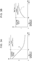
- FIG. 3A is a graph illustrating the relationship between the remaining distance S to the guide intersection C and the magnification X (solid line) of the guide image G.
- the horizontal axis indicates the remaining distance S
- the vertical axis indicates the magnification X of the guide image G.
- a period for which the remaining distance S is larger than the threshold S th corresponds to a period in the first display state.
- a period for which the remaining distance S is 0 or more and the threshold S th or less corresponds to a period in the second display state.
- the magnification X of the guide image G becomes monotonously larger as the remaining distance S to the guide intersection C becomes shorter.
- the control section 20 When the guide intersection C is specified, the control section 20, through the function of the display control section 21c, specifies the bracket of the turning angle ⁇ to which the turning angle ⁇ corresponding to the travel direction at the guide intersection C belongs, and acquires the reference guide image G S correlated with the specified bracket of the turning angle ⁇ from the reference image DB 30c as an enlargement target. The control section 20 then acquires the magnification X corresponding to the remaining distance S from the display setting data 30b, and enlarges the reference guide image G S corresponding to the travel direction at the guide intersection C with the acquired magnification X to generate the guide image G.
- the size of the guide image G becomes larger as the remaining distance S becomes shorter, that is, the degree of approach becomes larger.
- the control section 20 through the function of the display control section 21c, superimposes the shape image M, which represents the shape of the connected roads connected to the guide intersection C, on the forward image, and causes the display 45 to display the guide image G as superimposed on the forward image such that the guide image G represents on the shape image M an entry road for entry into the guide intersection C based on the information on the path and an exit road for exit from the guide intersection C based on the information on the path.
- the control section 20 When the guide intersection C is specified, the control section 20, through the function of the display control section 21c, specifies the bracket of the connection angle ⁇ of each connected road connected to the guide intersection C, and acquires the reference shape image M S corresponding to the combination of the brackets of the connection angle ⁇ at which the connected roads are connected from the reference image DB 30c as an enlargement target. Next, the control section 20 acquires the magnification X matching the remaining distance S from the display setting data 30b, and enlarges the reference shape image M S which represents the shape of the connected roads connected to the guide intersection C with the acquired magnification X to generate the shape image M. That is, the control section 20 generates the guide image G and the shape image M by enlarging the reference guide image G S and the reference shape image M S with the same magnification.
- FIG. 2D illustrates the shape image M on which the guide image G is superimposed. As illustrated in the drawing, the entry portion I of the guide image G is superimposed on the image A 1 of the entry road of the shape image M, and the exit portion O of the guide image G is superimposed on an image A 2 of the exit road of the shape image M. This allows the guide image G on the shape image M to represent the entry road for entry into the guide intersection C and the exit road for exit from the guide intersection C.
- the reference image DB 30c stores the reference guide image G S and the reference shape image M S with the length ( FIG. 2B ) of the center line i of the entry portion I in the reference guide image G S and the length ( FIG. 2C ) of the center line a 1 of the image A 1 of the entry road in the reference shape image M S coinciding with each other.
- the control section 20 though the function of the display control section 21c, superimposes the guide image G on a base image, and causes the display 45 to display the base image as superimposed on the forward image.
- the control section 20 generates a base image in a shape that accommodates the guide image G and the shape image M, and in a color that is different from those of the guide image G and the shape image M.
- the control section 20 generates a rectangular base image having the same height as the height of the shape image M and having the same width as the width of the shape image M.
- the control section 20 then further superimposes the shape image M, on which the guide image G is superimposed, on the base image such that the upper and lower ends of the shape image M coincide with the upper and lower ends, respectively, of the base image and such that the left and right ends of the shape image M coincide with the left and right ends, respectively, of the base image.
- This allows the lower end of the guide image G (the lower end of the entry portion I), the lower end of the shape image M (the lower end of the image A 1 of the entry road), and the lower end of the base image to be located at the same position in the longitudinal direction. It is desirable that the respective colors of the guide image G, the shape image M, and the base image are different from each other in hue angle, saturation, and brightness by a predetermined criterion or more.
- the control section 20 In the first display state, the control section 20, though the function of the display control section 21c, causes the display 45 to display the guide image G which represents the travel direction as superimposed on the forward image in a portion of the forward image other than the image of the guide intersection C.
- the control section 20 sets the position of superimposition of the guide image G to a portion of the forward image above a vanishing point W as the portion of the forward image other than the image of the guide intersection C.
- the height of the vanishing point W in the forward image can be specified on the basis of the optical specifications of the camera 44 stored in the display setting data 30b.
- the position of superimposition of the guide image G can be set with a low processing load.
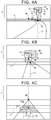
- FIGS. 4A and 4B each illustrate a forward image.
- the forward image of FIG. 4A is a forward image displayed in the case where the remaining distance S is larger than that of the forward image of FIG. 4B .
- the guide image G can be superimposed on a portion of the forward image other than the image of the guide intersection C (hatched).
- the guide image G with a larger size is superimposed on the forward image of FIG. 4B with a shorter remaining distance S compared to the forward image of FIG. 4A with a longer remaining distance S.
- the control section 20 may specify the position of the image of the guide intersection C in the forward image through image recognition (recognition of an image of a feature that is peculiar to the intersection) or on the basis of the map information 30a, and set the position of superimposition of the guide image G at a position that is different from the specified position of the image of the guide intersection C.
- image recognition recognition of an image of a feature that is peculiar to the intersection
- map information 30a maps the position of superimposition of the guide image G at a position that is different from the specified position of the image of the guide intersection C.
- the position of superimposition of the guide image G depends on the connection line image R. Therefore, the position of superimposition of the guide image G will be discussed in detail later.
- the control section 20 In the first display state, the control section 20, though the function of the display control section 21c, causes the display 45 to display the connection line image R, which connects between the image of the guide intersection C in the forward image and the guide image G, as superimposed on the forward image. That is, the control section 20 sets the position of one end of the connection line image R to the position of the image of the guide intersection C in the forward image, and sets the position of the other end of the connection line image R to the position of superimposition of the guide image G in the forward image. First, the control section 20 sets the position of the lower end of the connection line image R to a position in the forward image corresponding to a center position Q of the guide intersection C.
- the control section 20 specifies the center position Q of the guide intersection C on the basis of the node data of the map information 30a, and specifies the position in the forward image corresponding to the center position Q of the guide intersection C on the basis of the center position Q, the current position and the current orientation of the vehicle, and the optical specifications of the camera 44.
- the control section 20 may specify the position corresponding to the center position Q of the guide intersection C through image recognition in the forward image.
- the connection line image R is in the shape of an isosceles triangle with the vertex angle present on the lower side, and the height from the vertex angle to the base is defined as a length L.
- the connection line image R may have any linear shape that is narrower than the guide image G, and may not be in the shape of an isosceles triangle.
- FIG. 3B is a graph illustrating the length L (solid line) of the connection line image R specified in the display setting data 30b.
- the horizontal axis indicates the remaining distance S, and indicates the length L of the connection line image R.
- the length L of the connection line image R is specified so as to become shorter as the degree of approach to the guide intersection C becomes larger, that is, as the remaining distance S to the guide intersection C becomes shorter. Further, the length L of the connection line image R is specified such that the amount of decrease in length L of the connection line image R per unit amount of decrease in remaining distance S is increased as the remaining distance S becomes shorter.
- the control section 20 When the length L of the connection line image R matching the remaining distance S is acquired, the control section 20 generates the connection line image R, the height of which from the base to the vertex angle coincides with the length L.
- the control section 20 In the first display state, the control section 20, though the function of the display control section 21c, causes the display 45 to display the guide image G as superimposed on the forward image such that the guide image G descends toward the image of the guide intersection C in the forward image as the degree of approach becomes larger. That is, the control section 20 sets the position of superimposition of the guide image G to a lower position in the forward image as the remaining distance S becomes shorter.
- control section 20 sets the position of superimposition of the upper end of the connection line image R to a position above a height Y of the position corresponding to the center position Q of the guide intersection C by the length L of the connection line image R, and further sets the position of the upper end of the connection line image R to the position of superimposition of the lower end of the guide image G (the shape image M, the base image B).
- the guide image G can be descended since the image of the guide intersection C in the forward image descends and the length L of the connection line image R becomes shorter as the remaining distance S becomes shorter.
- the position of superimposition of the guide image G (the shape image M, the base image B) in the longitudinal direction can be set in the manner described above.
- a connection line image R with a shorter length L is superimposed on the forward image of FIG. 4B with a shorter remaining distance S compared to the forward image of FIG. 4A with a longer remaining distance S.
- the guide image G is superimposed at a lower position on the forward image of FIG. 4B with a shorter remaining distance S compared to the forward image of FIG. 4A with a longer remaining distance S.
- the remaining distance S to the guide intersection C becomes shorter, the position of the image of the guide intersection C in the forward image descends.
- the remaining distance S is the threshold S th
- the position of the image of the guide intersection C is lowest, and the length L of the connection line image R is shortest.
- the length L of the connection line image R is set such that the guide image G can be superimposed on the region J above the vanishing point W also in this case. Specifically, a position in the forward image corresponding to the center position Q of the intersection in the average shape for a case where the remaining distance S is the threshold S th is specified on the basis of the optical specifications of the camera 44. Setting is made such that the length L of the connection line image R for a case where the remaining distance S is the threshold S th is longer than the distance in the longitudinal direction between the specified position and the vanishing point W. This allows the guide image G to be superimposed on the region J above the vanishing point Win the first display state.
- the control section 20 though the function of the display control section 21c, causes the display 45 to display the connection line image R as superimposed on the forward image such that the tilt of a center line r of the connection line image R in the width direction in the forward image is kept constant.
- the control section 20 keeps the tilt of the center line r of the connection line image R in the width direction constant by keeping the center line r of the connection line image R in the width direction extending in the longitudinal direction of the forward image (the vertical direction of the forward image).
- the tilt of the center line r of the connection line image R in the width direction may be kept constant with the center line r inclined with respect to the longitudinal direction of the forward image.
- the control section 20 though the function of the display control section 21c, causes the display 45 to display the guide image G as superimposed on the forward image such that the entry portion I of the guide image G is superimposed on the extension line of the center line r of the connection line image R in the width direction in the forward image. That is, the control section 20 sets the position of superimposition of the guide image G in the lateral direction such that both the center line i of the entry portion I of the guide image G in the width direction and the center line r of the connection line image R in the width direction are positioned on a reference line U (broken line).
- U broken line
- connection line image R Since the lower end of the connection line image R is set to a position in the forward image corresponding to the center position Q of the guide intersection C, the reference line U extends in the longitudinal direction to pass through a position in the forward image corresponding to the center position Q of the guide intersection C.
- the control section 20 though the function of the display control section 21c, causes the display 45 to display the guide image G as superimposed on the image of the guide intersection C in the forward image. That is, in the second display state, the control section 20 does not superimpose the guide image G together with the connection line image R as in the first display state, but superimposes only the guide image G on the forward image.
- the size and the position of superimposition of the guide image G in the second display state will be described below.
- the control section 20 In the second display state, the control section 20, though the function of the display control section 21c, causes the display 45 to display the guide image G, which is analogous to the guide image G displayed on the display 45 as superimposed on the forward image in the first display state, as superimposed on the forward image. More specifically, in the second display state, the control section 20 causes the display 45 to display the guide image G, which is obtained by enlarging the guide image G displayed on the display 45 as superimposed on the forward image in the first display state, as superimposed on the forward image. Also in the second display state, the guide image G is generated by a technique that is similar to that employed in the first display state.
- the control section 20 acquires the magnification X of the guide image G matching the remaining distance S from the display setting data 30b ( FIG. 3A ), and enlarges the reference guide image G S representing the travel direction at the guide intersection C with the acquired magnification X to generate the guide image G.
- the guide image G obtained by enlarging the reference guide image G S is generated, and therefore the guide image G in the first display state and the guide image G in the second display state are analogous to each other.
- the magnification X of the guide image G in the second display state is set to be larger than the magnification X of the guide image G in the first display state.
- the guide image G which is obtained by enlarging the guide image G displayed in the first display state, is displayed in the second display state.
- the control section 20 though the function of the display control section 21c, causes the display 45 to display the guide image G as superimposed on the forward image such that the size of the guide image G becomes larger as the degree of approach becomes larger.
- the magnification X of the guide image G becomes larger as the degree of approach to the guide intersection C becomes larger, that is, the remaining distance S to the guide intersection C becomes shorter. That is, the control section 20 can make the size of the guide image G larger as the remaining distance S to the guide intersection C becomes shorter.
- the magnification X of the guide image G in the second display state is set to have the same tilt as the tilt of the magnification with which an image of the intersection in the average shape in the forward image is enlarged in accordance with a decrease in remaining distance S. This allows the size of the guide image G to become larger so as to follow an increase in size of the image of the guide intersection C in the forward image along with a decrease in remaining distance S.
- the tilt of the magnification X is gentler in the first display state than in the second display state. This can prevent the size of the guide image G from becoming too small in the first display state in which the remaining distance S is long.
- the control section 20 In the second display state, the control section 20, though the function of the display control section 21c, sets the position of superimposition of the guide image G in the forward image such that the guide image G is present on the image of the guide intersection C. In the embodiment, the control section 20 sets the position of superimposition of the guide image G such that the bent point T of the guide image G overlaps a position in the forward image corresponding to the center position Q of the guide intersection C.
- FIG. 4C illustrates a forward image in the second display state. As illustrated in the drawing, the guide image G is superimposed on the image of the guide intersection C.
- the display state on the display 45 is brought into the first display state when the remaining distance S to the guide intersection C is larger than the threshold S th , that is, the image of the guide intersection C is small in the forward image.
- the control section 20 does not superimpose the guide image G on the image of the guide intersection C, but superimposes the guide image G on a portion of the forward image other than the image of the guide intersection.
- the travel direction at the guide intersection C can be reliably recognized.
- the display state on the display 45 is brought into the second display state when the remaining distance S to the guide intersection C is equal to or less than the threshold S th , that is, a large image of the guide intersection C can be visually recognized in the forward image.
- the control section 20 superimposes the guide image G on the image of the guide intersection C in the forward image.
- the exit road an image of which is located ahead in the travel direction at the guide intersection C, can be easily recognized by contrasting the image of the guide intersection C in the forward image and the guide image G with each other. That is, the exit road at the guide intersection C can be recognized in a situation where the driver can clearly recognize the image of the guide intersection C in the forward image or the actual scene.
- guidance on the travel direction at the guide intersection C can be provided in a display manner that is suitable for the remaining distance S to the guide intersection C by causing a transition from the first display state to the second display state.
- the guide image G is not superimposed on the image of the guide intersection C in the forward image.
- the guide image G superimposed on a portion of the forward image other than the image of the guide intersection C can be visually recognized, without confusion, when the remaining distance S to the guide intersection C is larger than the threshold S th .
- the guide image G is not superimposed on a portion of the forward image other than the image of the guide intersection C.
- the guide image C superimposed on the image of the guide intersection C in the forward image can be visually recognized, without confusion, when the remaining distance S to the guide intersection C is equal to or less than the threshold S th .
- the image of the guide intersection C and the travel direction at the guide intersection C can be recognized as correlated with each other in the forward image in either of the first display state and the second display state. That is, the position of the guide intersection C and the travel direction at the guide intersection C can be recognized as correlated with each other continuously even if a transition is made from the first display state to the second display state. Further, a transition from the first display state to the second display state allows recognizing that the remaining distance S to the guide intersection C has become shorter.
- the guide image G in the first display state and the guide image G in the second display state are analogous to each other, it is possible to intuitively recognize that the guide image G provides guidance on the same travel direction at the same guide intersection C continuously even if a transition is made from the first display state to the second display state. Since the guide image G in the second display state is an image obtained by enlarging the guide image G in the first display state, the guide image G can be easily contrasted with the image of the guide intersection C which has become larger in the second display state.
- control section 20 makes the length L of the connection line image R shorter as the remaining distance S to the guide intersection C becomes shorter. Since the length L of the connection line image R is varied in a one-dimensional direction on the plane of projection of the forward image, the length L of the connection line image R can be easily recognized in the forward image. Thus, the remaining distance S to the guide intersection C can be easily recognized. In addition, it is possible to ideologically correlate the fact that the remaining distance S to the guide intersection C becomes shorter and the fact that the length L of the connection line image R becomes shorter, which allows ideologically recognizing that the remaining distance S becomes shorter as the length of the connection line image R becomes shorter.
- connection line image R the image of the guide intersection C and the guide image G, which are connected to each other by the connection line image R, are caused to approach each other by making the length L of the connection line image R shorter.
- the connection between the image of the guide intersection C and the guide image G can be emphasized as the remaining distance S to the guide intersection C becomes shorter, which allows ideologically recognizing that the timing to cause the vehicle to travel in the travel direction represented by the guide image G at the guide intersection C is drawing near, that is, the remaining distance S to the guide intersection C is becoming shorter.
- connection line image R is present between the image of the guide intersection C and the guide image G, and therefore the remaining distance S to the guide intersection C can be recognized without moving the line of vision away from a location between the image of the guide intersection C and the guide image G. Since the length of the connection line image R is made shorter in advance in the first display state, further, an impression that the connection line image R vanishes at the timing of a transition from the first display state to the second display state can be lessened. As illustrated in FIG. 3B , in addition, the amount of decrease in length L of the connection line image R per unit amount of decrease in remaining distance S is increased as the remaining distance S becomes shorter. Therefore, the fact that the remaining distance S becomes shorter can be expressed more emphatically as the remaining distance S becomes shorter.
- the guide image G superimposed above the image of the guide intersection C is descended in advance toward the image of the guide intersection C in the first display state, an impression can be lessened that the guide image G is abruptly descended onto the image of the guide intersection C at the timing of a transition from the first display state to the second display state.
- the guide image G reaches a location on the image of the guide intersection C in the second display state after the guide image G is gradually descended in the first display state, which allows intuitively recognizing that guidance on the travel direction at the same guide intersection C is continuously provided.
- the image of the guide intersection C and the guide image G are arranged vertically at closer positions in the forward image, which makes it possible to easily contrast the image of the guide intersection C and the travel direction represented by the guide image G with each other.
- the fact that the remaining distance S to the guide intersection C becomes shorter can be easily recognized in correlation with the fact that the height of the guide image G becomes smaller.
- the control section 20 superimposes the guide image G on the forward image such that the size of the guide image G becomes larger as the remaining distance S becomes shorter. This attracts attention to the guide image G more strongly as the remaining distance S to the guide intersection C becomes shorter in the first display state. Further, the length L of the connection line image R becomes shorter contrastively as the size of the guide image G becomes larger, which allows more strongly recognizing that the remaining distance S is becoming shorter. Since the guide image G in the second display state is an image obtained by enlarging the guide image G in the first display state, in addition, the size of the guide image G, which has become larger in the first display state, can be caused to continuously become larger at the time of a transition to the second display state. Accordingly, a smooth transition can be made from the first display state to the second display state. Thus, it is possible to intuitively recognize that guidance on the travel direction at the same guide intersection is continuously provided at the time of a transition from the first display state to the second display state.
- the control section 20 in the second display state, the control section 20 superimposes the guide image G on the forward image such that the size of the guide image G becomes larger as the remaining distance S becomes shorter.
- the control section 20 in the first display state, the control section 20 superimposes the shape image M, which represents the shape of the connected roads connected to the guide intersection C, on the forward image, and superimposes the guide image G on the forward image such that the guide image G represents on the shape image M an entry road for entry into the guide intersection C and an exit road for exit from the guide intersection C.
- This allows easily recognizing which roads, among the connected roads connected to the guide intersection C, are the entry road and the exit road in the first display state.
- the viewability of the guide image G on the base image B can be secured, without depending on the color of the forward image, by superimposing the guide image G on the base image B.
- the guide image G is directly superimposed on the image of the guide intersection C without being superimposed on the base image B. This allows the guide image G and the image of the guide intersection C to be directly contrasted with each other, which allows easily recognizing the travel direction represented by the guide image G.
- the control section 20 superimposes the connection line image R on the forward image such that the tilt of the center line r of the connection line image R in the width direction in the forward image is kept constant. This keeps the direction in which the length L of the connection line image R becomes shorter constant, which allows easily recognizing that the connection line image R is becoming shorter. Further, since the direction in which the connection line image R becomes shorter is kept constant, the image of the guide intersection C and the guide image G can be caused to approach each other as the connection line image R becomes shorter. This allows clearly recognizing that the remaining distance S to the guide intersection C is becoming shorter. Further, the guide image G is moved linearly toward the image of the guide intersection C, which allows recognizing that the image of the guide intersection C is present ahead in the direction of movement of the guide image G.
- the control section 20 in the first display state, superimposes the guide image G on the forward image such that the entry portion I is superimposed on the extension line of the center line r of the connection line image R in the width direction in the forward image.
- This provides the driver with an impression that direct entry to the entry portion I of the guide image G can be made by following the connection line image R in the length direction from the image of the guide intersection C. That is, the entry direction d 1 at the guide intersection C can be continuously expressed by the connection line image R and the entry portion I of the guide image G.
- FIG. 5 is a flowchart of an intersection guide process.
- the intersection guide process is a process in which the display state on the display 45 is updated each time the remaining distance S from the vehicle to the guide intersection C is updated.
- the control section 20 through the function of the path information acquisition section 21a, acquires information on a path (step S100). That is, the control section 20 searches for an expected travel path for reaching a destination location on the basis of the map information 30a to acquire information indicating the expected travel path.
- the control section 20, through the function of the travel direction acquisition section 21b acquires the current position and the current orientation of the vehicle (step S105). Further, the control section 20, through the function of the display control section 21c, acquires a forward image (step S110).
- the control section 20 through the function of the display control section 21c, acquires a travel direction at a guide intersection C (step S115).
- the control section 20 specifies an intersection that the vehicle travels through next, among intersections on the expected travel path, a turning angle ⁇ of which is equal to or more than a threshold, as the guide intersection C.
- the turning angle ⁇ is an angle formed by the exit direction d 2 with respect to the entry direction d 1 for entry into the intersection.
- the control section 20 acquires an entry direction d 1 and an exit direction d 2 at the guide intersection C as the travel direction at the guide intersection C on the basis of the direction of an entry road for entry into the guide intersection C and the direction of an exit road for exit from the guide intersection C.
- control section 20 through the function of the display control section 21c, acquires a remaining distance S to the guide intersection C (step S120). That is, the control section 20 specifies the linear distance from the current position of the vehicle to the center position Q of the guide intersection C as the remaining distance S.
- control section 20 determines whether or not the vehicle has passed through the guide intersection C (step S125). Specifically, the control section 20 determines that the guide intersection C has been passed through in the case where the remaining distance S is 0. In the case where it is determined that the vehicle has passed through the guide intersection C (step S125: Y), the control section 20 returns to step S100. That is, in the case where the vehicle has already passed through the guide intersection C, the control section 20 determines that it is no longer necessary to continuously provide guidance on the guide intersection C for which guidance on the travel direction has been provided so far, and executes a process for a next guide intersection C.
- step S130 determines whether or not the remaining distance S to the guide intersection C is equal to or less than the threshold S th (step S130). That is, the control section 20 determines whether or not the degree of approach to the guide intersection C is equal to or more than a threshold. In the case where it is not determined that the remaining distance S to the guide intersection C is equal to or less than the threshold S th (step S130: N), the control section 20, through the function of the display control section 21c, performs a preparation process for performing display in the first display state (step S135). The preparation process for performing display in the first display state will be described below.
- the control section 20 specifies the bracket of the turning angle ⁇ to which the turning angle ⁇ corresponding to the travel direction at the guide intersection C belongs, and acquires a reference guide image G S correlated with the specified bracket of the turning angle ⁇ from the reference image DB 30c. Further, the control section 20 specifies the bracket of the connection angle ⁇ of each connected road connected to the guide intersection C, and acquires a reference shape image M S corresponding to the combination of the brackets of the connection angle ⁇ at which the connected roads are connected from the reference image DB 30c. In addition, the control section 20 references the display setting data 30b to acquire a magnification X of the guide image G corresponding to the remaining distance S.
- the control section 20 then generates a guide image G and a shape image M matching the remaining distance S by enlarging the reference guide image G S and the reference shape image M S with the acquired magnification X. That is, the control section 20 generates a guide image G and a shape image M with a larger size as the degree of approach is larger (as the remaining distance S is shorter). The control section 20 generates a base image B that is different in color from the guide image G and the shape image M.
- control section 20 references the display setting data 30b to acquire a length L of a connection line image R corresponding to the remaining distance S, and generates a connection line image R with the acquired length L. That is, the control section 20 generates a connection line image R with a shorter length L as the degree of approach is larger (as the remaining distance S is shorter).
- control section 20 specifies a position in the forward image corresponding to the center position Q of the guide intersection C on the basis of the map information 30a, the current position, the current orientation, and the optical specifications of the camera 44, and sets a reference line U that extends in the longitudinal direction to pass through the position corresponding to the center position Q of the guide intersection C.
- the control section 20 sets the position of superimposition of the connection line image R and the guide image G (the shape image M, the base image B) such that the connection line image R connects between the position corresponding to the center position Q of the guide intersection C and the entry portion I of the guide image G on the reference line U.
- control section 20 causes the display 45 to display the connection line image R, the guide image G, the shape image M, and the base image B, which are generated in the preparation process in step S135, as superimposed at the position of superimposition set in the preparation process in step S135 (step S140).
- This allows the image of the guide intersection C and the entry portion I of the guide image G to be connected with each other by the connection line image R on the reference line U which passes through the position in the forward image corresponding to the center position Q of the guide intersection C as illustrated in FIGS. 4A and 4B .
- the guide image G, the shape image M, and the base image B are eventually superimposed on the forward image, and the order of superimposition is not limited to that in the example discussed above.
- step S145 the control section 20 acquires a reference guide image G S correlated with the bracket to which the turning angle ⁇ at the guide intersection C belongs from the reference image DB 30c. Further, the control section 20 references the display setting data 30b to acquire a magnification X of the guide image G corresponding to the remaining distance S. The control section 20 then generates a guide image G matching the remaining distance S by enlarging the reference guide image G S with the acquired magnification X.
- control section 20 generates a guide image G with a larger size as the degree of approach is larger (as the remaining distance S is shorter). Further, the control section 20 sets the position of superimposition of the guide image G such that the bent point T of the guide image G overlaps a position in the forward image corresponding to the center position Q of the guide intersection C.
- control section 20 though the function of the display control section 21c, causes the display 45 to display the guide image G as superimposed at the position of superimposition set as described above (step S150).
- the display state on the display 45 can be caused to transition in accordance with the remaining distance S, which is gradually decreased, by repeatedly performing the process described above.
- the control section 20 may cause the display 45 to display the guide image G as superimposed on the forward image such that the entry portion I of the guide image G is maintained on the same line in the forward image.
- the control section 20 maintains the position of the reference line U, on which both the center line i of the entry portion I of the guide image G in the width direction and the center line r of the connection line image R in the width direction are superimposed, on the center line of the forward image in the lateral direction.
- the control section 20 In a period including the starting time of the period in the second display state, the control section 20 superimposes the center line i of the entry portion I of the guide image G in the width direction on the reference line U maintained on the center line of the forward image in the lateral direction. This maintains the center line i of the entry portion I in the width direction on the reference line U maintained on the center line of the forward image in the lateral direction at the timing of a transition from the first display state to the second display state. As the vehicle approaches the guide intersection C, it is more likely that the guide intersection C is present right ahead of the vehicle.
- a reference value (that is larger than the threshold S th ) of the remaining distance S may be set, with which it can be considered that the image of the guide intersection C is always present on the center line of the forward image in the lateral direction.
- a maintenance period may be started, for which the position of the reference line U is maintained on the center line of the forward image in the lateral direction in the case where the remaining distance S to the guide intersection C becomes equal to or less than the reference value, and further, a transition may be made to the second display state with the position of the reference line U maintained in the case where the remaining distance S becomes equal to or less than the threshold S th .
- the control section 20 may start a maintenance period, for which the position of the reference line U is maintained on the center line of the forward image in the lateral direction, in the case where it is determined on the basis of image recognition on the forward image or the like that the image of the guide intersection C is present on the center line of the forward image in the lateral direction.
- the control section 20 may acquire the reference line U at the ending time of the first display state, and set the center line i of the entry portion I of the guide image G in the width direction at the starting time of the second display state on the acquired reference line U.
- the control section 20 may end the first display state and make a transition to the second display state in the case where the remaining distance S is equal to or less than the threshold S th and the reference line U in the first display state falls within a predetermined distance from the center line of the forward image in the lateral direction.
- the center position Q of the guide intersection C is already positioned around a location right ahead of the vehicle, and it can be considered that the position of the image of the guide intersection C will not be moved significantly in the lateral direction of the forward image.
- the center line i of the entry portion I of the guide image G in the width direction can be superimposed on the image of the guide intersection C by making a transition to the second display state, and setting the center line i of the entry portion I of the guide image G in the width direction on the reference line U (the reference line U at the ending time of the first display state).
- the driver can recognize that the guide image G represents the entry direction d 1 for the same guide intersection C.
- the driver can be prevented from feeling uncomfortable about a shake of the entry portion I of the guide image G in the forward image around a transition from the first display state to the second display state. Since the entry portion I is maintained on the reference line U which is the center line of the forward image in the lateral direction around a transition from the first display state to the second display state, in particular, it is possible to provide an impression that the vehicle can be advanced right forward to directly travel in the entry direction d 1 indicated by the entry portion I.
- the control section 20, through the function of the display control section 21c, may determine that the degree of approach is equal to or more than a threshold. That is, the control section 20 may cause the display state on the display 45 to transition from the first display state to the second display state in the case where the size of the image of the guide intersection C in the forward image is equal to or more than a predetermined value. For example, the control section 20 may determine that the size of the image of the guide intersection C is equal to or more than a predetermined value in the case where the image of the guide intersection C becomes so large that the guide image G is accommodated in the image of the guide intersection C.
- control section 20 may determine that the size of the image of the guide intersection C in the forward image is equal to or more than a predetermined value in the case where the size of the image of the guide intersection C is at a predetermined proportion with respect to the size of the guide image G. This prevents the guide image G from being superimposed on the image of the guide intersection C with the size of the image of the guide intersection C being too small for the guide image G.
- the control section 20 may specify the size of the image of the guide intersection C through image recognition on the forward image. For example, the control section 20 may recognize an image of a stop line formed to stop vehicles at a location before the guide intersection C through image recognition, and specify the size of the image of the guide intersection C on the basis of the position of the image of the stop line recognized through image recognition.
- control section 20 may specify that the distance between the position, in the longitudinal direction, of an image of a stop line for the guide intersection C formed on the entry road for entry into the guide intersection C and the position, in the longitudinal direction, of an image of a stop line for the guide intersection C formed on an opposite lane of a driving lane connected to the guide intersection C corresponds to the size of the image of the guide intersection C in the longitudinal direction.
- opposite lane refers to a lane (not illustrated in FIG. 2A ) which is arranged side by side with the driving lane connected to the guide intersection C in the width direction and on which vehicles travel in the direction opposite to the direction in which vehicles travel on the driving lane.
- the control section 20 may specify the size of the guide intersection C on the basis of the map information 30a, and upwardly revise the threshold S th of the remaining distance S in the case where the size of the guide intersection C is larger than the size of the intersection in the average shape.
- the control section 20 may downwardly revise the threshold S th of the remaining distance S in the case where the size of the guide intersection C is smaller than the size of the intersection in the average shape.
- the control section 20 may set the remaining distance S with which it is considered that no image of an intersection other than the guide intersection C is present in the forward image as the threshold S th .
- the threshold S th of the remaining distance S with which it is considered that no image of an intersection other than the guide intersection C is present in the forward image may be set on the basis of the smallest value of the lengths of links indicated by the link data of the map information 30a.
- the image of the guide intersection C can be clearly represented by the connection line image R (the vertex angle at the lower end), and therefore erroneous recognition of the guide intersection C can be prevented even in the case where the image of the guide intersection C and the image of a non-guide target intersection are mistakable in the forward image.
- control section 20 may superimpose the guide image G, the size of which has been reduced compared to the original size specified by the magnification X of FIG. 3A , on the image of the guide intersection C in the case where the image of the guide intersection C and the image of a non-guide target intersection are mistakable in the forward image.
- the image of the guide intersection C can be represented more clearly as the size of the guide image G is smaller, and therefore erroneous recognition of the guide intersection can be prevented.
- control section 20 through the function of the display control section 21c, may set the threshold S th of the remaining distance S to be smaller in the case where there is any obstacle present on the road between the vehicle and the guide intersection C than in the case where there is no obstacle present on the road between the vehicle and the guide intersection C.
- the control section 20 may determine that there is any obstacle present on the road between the vehicle and the guide intersection C, and downwardly revise the threshold S th of the remaining distance S. This makes it possible to delay a transition from the first display state to the second display state in the case where the image of the guide intersection C is hidden by an image of the obstacle.
- the control section 20, through the function of the display control section 21c, may specify the distance along the way from the current position of the vehicle to the center position Q of the guide intersection C as the remaining distance S. Further, the control section 20 may specify the distance from the current position of the vehicle to a boundary line between the guide intersection C and the entry road as the remaining distance S.
- the position of the boundary line between the guide intersection C and the entry road can be specified on the basis of the width of a connected road that crosses the entry road at the guide intersection C indicated by the link data of the map information 30a.
- the width of the connected road that crosses the entry road can be specified on the basis of the link data of the map information 30a.
- control section 20 may specify the position of the image of the guide intersection C (the center position or the position of the boundary line with the entry road) in the forward image through image recognition of the forward image, and specify the remaining distance S on the basis of the position of the image of the guide intersection C.
- the control section 20, through the function of the display control section 21c, may establish a state in which both the guide image G and the connection line image R are superimposed on the forward image, and may collectively superimpose an image obtained by coupling the guide image G and the connection line image R to each other on the forward image.
- the connection line image R may provide the driver with an impression that the image of the guide intersection C and the guide image G are connected to each other, and both ends of the connection line image R in the length direction may not necessarily be present on the image of the guide intersection C and the guide image G.
- the amount of decrease in length L of the connection line image R per unit amount of decrease in remaining distance S may be constant.
- making the length L of the connection line image R shorter also includes shrinking the connection line image R such that the width of the connection line image R becomes smaller together with the length thereof.
- the control section 20 may not cause the display state on the display 45 to transition from the first display state to the second display state in accordance with the remaining distance S, and may reduce the length L of the connection line image R such that the remaining distance S becomes 0.
- the control section 20 though the function of the display control section 21c, may superimpose at least the guide image G and the connection line image R, and may not necessarily superimpose the shape image M and the base image B.
- control section 20 may not make the size of the guide image G larger as the remaining distance S becomes shorter in at least one of the first display state and the second display state. Further, the guide image G may be switched into a non-analogous image at the timing of a transition from the first display state to the second display state.
- the guide image G may be an image that allows recognition of an exit road, and may not necessarily include the entry portion I.
- FIG. 2E illustrates an example of a road surface at the guide intersection C to which four connected roads are connected. It is only necessary that the road surface at the guide intersection C should include at least an in-intersection road surface C 1 (hatched upwardly toward the right) which is a road surface of a region in which the connected roads connected to the guide intersection C overlap each other, and the road surface at the guide intersection C may further include around-intersection road surfaces C 2 (hatched downwardly toward the right) which are road surfaces of regions within a predetermined distance k from the in-intersection road surface C 1 , among the road surfaces of the connected roads.
- in-intersection road surface C 1 hatchched upwardly toward the right
- C 2 hatchched downwardly toward the right
- the control section 20 may superimpose the guide image G on an image of any of the around-intersection road surfaces C 2 within the predetermined distance k from the in-intersection road surface C 1 .
- the guide image G and the image of the guide intersection C can be contrasted with each other on the images of the around-intersection road surfaces C 2 within the predetermined distance k from the in-intersection road surface C 1 even if the guide image G is not superimposed on the image of the in-intersection road surface C 1 .
- an expression such as a road sign (arrow) that provides guidance on the exit direction d 2 can be provided on a road surface before an intersection by superimposing the guide image G on the image of the around-intersection road surface C 2 on the entry road for entry into the guide intersection C.
- the forward image may be obtained by drawing a forward scene on the basis of the map information 30a.
- the guide image G may be drawn at the same time as the forward image.
- causing the display 45 to display the guide image G as superimposed on the forward scene may be causing the display 45 to display the guide image G to result in superimposition of the guide image G on the forward scene.
- the display 45 may display at least the guide image G, and may not display the forward image. That is, the display 45 may superimpose the guide image G on the actual forward scene that the driver visually recognizes over the windshield of the vehicle.
- the display 45 may be a semi-transmissive type that allows the actual forward scene to be seen through the display 45 so that the guide image G is superimposed on the actual forward scene.
Landscapes
- Engineering & Computer Science (AREA)
- Radar, Positioning & Navigation (AREA)
- Remote Sensing (AREA)
- Automation & Control Theory (AREA)
- Physics & Mathematics (AREA)
- General Physics & Mathematics (AREA)
- Theoretical Computer Science (AREA)
- Multimedia (AREA)
- Computer Hardware Design (AREA)
- Navigation (AREA)
- Instructional Devices (AREA)
- Traffic Control Systems (AREA)
Claims (10)
- Kreuzungsführungssystem, mit:einer Pfadinformationenbezugseinrichtung (21a) zum Beziehen von Informationen über einen Pfad eines Fahrzeugs;einer Fahrtrichtungsbezugseinrichtung (21b) zum Beziehen einer Fahrtrichtung des Fahrzeugs an einer Führungskreuzung (C) voraus des Fahrzeugs auf der Basis der Informationen über den Pfad;einer Anzeigesteuerungseinrichtung (21c) zum Bewirken einer Anzeigesektion, um ein Führungsbild (G), das die Fahrtrichtung repräsentiert, auf einem Abschnitt einer Vorwärtsszene voraus des Fahrzeugs, der sich von einem Bild der Führungskreuzung (C) unterscheidet, überlagert anzuzeigen, und zum Bewirken der Anzeigesektion, um ein Verbindungslinienbild (R) auf der Vorwärtsszene überlagert anzuzeigen, wobei das Verbindungslinienbild (R) eine Verbindung zwischen dem Bild der Führungskreuzung (C) in der Vorwärtsszene und dem Führungsbild (G) ist,dadurch gekennzeichnet, dass
die Anzeigesteuerungseinrichtung (21c) konfiguriert ist, die Anzeigesektion zu bewirken, um das Verbindungslinienbild (R) auf der Vorwärtsszene derart überlagert anzuzeigen, dass eine Länge des Verbindungslinienbildes (R) kürzer wird, wenn ein Ausmaß einer Annäherung des Fahrzeugs zu der Führungskreuzung (C) größer wird, wobei das Ausmaß einer Annäherung ein Index ist, der angibt, wie nahe sich das Fahrzeug an der Führungskreuzung (C) befindet. - Kreuzungsführungssystem gemäß Anspruch 1, wobeidie Anzeigesteuerungseinrichtung (21c) konfiguriert ist, die Anzeigesektion zu bewirken, um das Führungsbild (G) auf einem Abschnitt der Vorwärtsszene oberhalb des Bildes der Führungskreuzung (C) überlagert anzuzeigen, und konfiguriert ist, die Anzeigesektion zu bewirken, um das Führungsbild (G) auf der Vorwärtsszene derart überlagert anzuzeigen, dass das Führungsbild (G) in Richtung des Bildes der Führungskreuzung (C) in der Vorwärtsszene abgesenkt wird, wenn das Ausmaß einer Annäherung größer wird.
- Kreuzungsführungssystem gemäß Anspruch 1 oder 2, wobeidie Anzeigesteuerungseinrichtung (21c) konfiguriert ist, die Anzeigesektion zu bewirken, um das Führungsbild (G) auf der Vorwärtsszene derart überlagert anzuzeigen, dass eine Größe des Führungsbildes (G) größer wird, wenn das Ausmaß einer Annäherung größer wird.
- Kreuzungsführungssystem gemäß einem der Ansprüche 1 bis 3, wobeidie Anzeigesteuerungseinrichtung (21c) konfiguriert ist, die Anzeigesektion zu bewirken, um das Verbindungslinienbild auf dem Vorwärtsbild derart überlagert anzuzeigen, dass eine Neigung des Verbindungslinienbildes (R) in der Vorwärtsszene konstant gehalten wird.
- Kreuzungsführungssystem gemäß einem der Ansprüche 1 bis 4, wobei:das Führungsbild (G) einen Einfahrtsabschnitt (I), der die Fahrtrichtung auf einer Einfahrtsstraße zum Einfahren in die Führungskreuzung (C) basierend auf den Informationen über den Pfad angibt, und einen Ausfahrtsabschnitt, der die Fahrtrichtung auf einer Ausfahrtsstraße zum Ausfahren aus der Führungskreuzung (C) basierend auf den Informationen über den Pfad angibt, umfasst; unddie Anzeigesteuerungseinrichtung (21c) konfiguriert ist, die Anzeigesektion zu bewirken, um den Einfahrtsabschnitt (I) auf einer Erweiterungslinie des Verbindungslinienbildes (R) in der Vorwärtsszene überlagert anzuzeigen.
- Kreuzungsführungssystem gemäß einem der Ansprüche 1 bis 5, wobeidie Anzeigesteuerungseinrichtung (21c) konfiguriert ist, ein Formbild (M), das eine Form einer verbundenen Straße, die mit der Führungskreuzung (C) verbunden ist, repräsentiert, zu überlagern, und konfiguriert ist, die Anzeigesektion zu bewirken, um das Führungsbild (G) auf der Vorwärtsszene derart überlagert anzuzeigen, dass das Führungsbild (G) auf dem Formbild (M) eine Einfahrtsstraße zum Einfahren in die Führungskreuzung (C) und eine Ausfahrtsstraße zum Ausfahren aus der Führungskreuzung (C) repräsentiert.
- Kreuzungsführungssystem gemäß einem der Ansprüche 1 bis 6, wobeidie Anzeigesteuerungseinrichtung (21c) konfiguriert ist, ein Basisbild auf der Vorwärtsszene zu überlagern, wobei das Basisbild ein Bild ist, das in einer sich von dem Führungsbild unterscheidenden Farbe angezeigt wird, und die Anzeigesektion bewirkt, um das Führungsbild (G) auf dem Basisbild überlagert anzuzeigen.
- Kreuzungsführungssystem gemäß einem der Ansprüche 1 bis 7, wobeiin dem Fall, in dem das Ausmaß einer Annäherung des Fahrzeugs zu der Führungskreuzung (C) größer oder gleich einem Schwellenwert wird, die Anzeigesteuerungseinrichtung (21c) konfiguriert ist, einen Übergang von einem ersten Anzeigezustand, in dem die Anzeigesektion bewirkt wird, das Führungsbild (G) und das Verbindungslinienbild (R) auf der Vorwärtsszene überlagert abzubilden, auf einen zweiten Anzeigezustand, in dem die Anzeigesektion bewirkt wird, das Führungsbild (G) auf dem Bild der Führungskreuzung (C) in der Vorwärtsszene überlagert anzuzeigen, durchzuführen.
- Kreuzungsführungsverfahren, mit:einem Pfadinformationenbezugsschritt (S100) des Beziehens von Informationen über einen Pfad eines Fahrzeugs;einem Fahrtrichtungsbezugsschritt (S115) des Beziehens einer Fahrtrichtung des Fahrzeugs an einer Führungskreuzung (C) voraus des Fahrzeugs auf der Basis der Informationen über den Pfad; undeinem Anzeigesteuerungsschritt (S135 bis S150) des Bewirkens einer Anzeigesektion, um ein Führungsbild (G), das die Fahrtrichtung repräsentiert, auf einem Abschnitt einer Vorwärtsszene voraus des Fahrzeugs, der sich von einem Bild der Führungskreuzung (C) unterscheidet, überlagert anzuzeigen, und des Bewirkens der Anzeigesektion, um ein Verbindungslinienbild (R) auf einer Vorwärtsszene überlagert anzuzeigen, wobei das Verbindungslinienbild (R) eine Verbindung zwischen dem Bild der Führungskreuzung (C) in der Vorwärtsszene und dem Führungsbild (G) ist,dadurch gekennzeichnet, dass
der Anzeigesteuerungsschritt umfasst, die Anzeigesektion zu bewirken, um das Verbindungslinienbild (R) auf der Vorwärtsszene derart überlagert anzuzeigen, dass eine Länge des Verbindungslinienbildes (R) kürzer wird, wenn ein Ausmaß einer Annäherung des Fahrzeugs zu der Führungskreuzung (C) größer wird, wobei das Ausmaß einer Annäherung ein Index ist, der angibt, wie nahe sich das Fahrzeug an der Führungskreuzung (C) befindet. - Kreuzungsführungsprogramm, das einen Computer bewirkt, um auszuführen:eine Pfadinformationenbezugsfunktion des Beziehens von Informationen über einen Pfad eines Fahrzeugs;eine Fahrtrichtungsbezugsfunktion des Beziehens einer Fahrtrichtung des Fahrzeugs an einer Führungskreuzung (C) voraus des Fahrzeugs auf der Basis der Informationen über den Pfad; undeine Anzeigesteuerungsfunktion des Bewirkens einer Anzeigesektion, um ein Führungsbild (G), das die Fahrtrichtung repräsentiert, auf einem Abschnitt einer Vorwärtsszene voraus des Fahrzeugs, der sich von einem Bild der Führungskreuzung (C) unterscheidet, überlagert anzuzeigen, und des Bewirkens der Anzeigesektion, um ein Verbindungslinienbild (R) auf einer Vorwärtsszene überlagert anzuzeigen, wobei das Verbindungslinienbild (R) eine Verbindung zwischen dem Bild der Führungskreuzung (C) in der Vorwärtsszene und dem Führungsbild (G) ist,dadurch gekennzeichnet, dass
der Anzeigesteuerungsschritt umfasst, die Anzeigesektion zu bewirken, um das Verbindungslinienbild (R) auf der Vorwärtsszene derart überlagert anzuzeigen, dass eine Länge des Verbindungslinienbildes (R) kürzer wird, wenn ein Ausmaß einer Annäherung des Fahrzeugs zu der Führungskreuzung (C) größer wird, wobei das Ausmaß einer Annäherung ein Index ist, der angibt, wie nahe sich das Fahrzeug an der Führungskreuzung (C) befindet.
Applications Claiming Priority (2)
| Application Number | Priority Date | Filing Date | Title |
|---|---|---|---|
| JP2012178816A JP6015228B2 (ja) | 2012-08-10 | 2012-08-10 | 交差点案内システム、方法およびプログラム |
| PCT/JP2013/057642 WO2014024513A1 (ja) | 2012-08-10 | 2013-03-18 | 交差点案内システム、方法およびプログラム |
Publications (3)
| Publication Number | Publication Date |
|---|---|
| EP2848896A1 EP2848896A1 (de) | 2015-03-18 |
| EP2848896A4 EP2848896A4 (de) | 2015-07-29 |
| EP2848896B1 true EP2848896B1 (de) | 2017-02-22 |
Family
ID=50067761
Family Applications (1)
| Application Number | Title | Priority Date | Filing Date |
|---|---|---|---|
| EP13828302.3A Not-in-force EP2848896B1 (de) | 2012-08-10 | 2013-03-18 | Kreuzungsführungssystem, -verfahren und -programm |
Country Status (5)
| Country | Link |
|---|---|
| US (1) | US9739628B2 (de) |
| EP (1) | EP2848896B1 (de) |
| JP (1) | JP6015228B2 (de) |
| CN (1) | CN104471354B (de) |
| WO (1) | WO2014024513A1 (de) |
Families Citing this family (21)
| Publication number | Priority date | Publication date | Assignee | Title |
|---|---|---|---|---|
| JP5935636B2 (ja) * | 2012-09-28 | 2016-06-15 | アイシン・エィ・ダブリュ株式会社 | 交差点案内システム、方法およびプログラム |
| WO2014197858A1 (en) * | 2013-06-06 | 2014-12-11 | Kustom Signals, Inc. | Traffic enforcement system with time tracking and integrated video capture |
| JP6446784B2 (ja) * | 2014-01-21 | 2019-01-09 | 株式会社デンソー | ナビゲーション装置 |
| CN105222801A (zh) * | 2014-06-13 | 2016-01-06 | 大陆汽车投资(上海)有限公司 | 导航提示方法及导航提示系统 |
| JP2016024004A (ja) * | 2014-07-18 | 2016-02-08 | 日産自動車株式会社 | 車両用表示装置 |
| CN110654306A (zh) * | 2015-04-10 | 2020-01-07 | 麦克赛尔株式会社 | 车辆 |
| KR101750876B1 (ko) * | 2015-05-28 | 2017-06-26 | 엘지전자 주식회사 | 차량용 디스플레이 장치 및 차량 |
| JP6593803B2 (ja) * | 2017-03-10 | 2019-10-23 | 株式会社Subaru | 画像表示装置 |
| US10527449B2 (en) * | 2017-04-10 | 2020-01-07 | Microsoft Technology Licensing, Llc | Using major route decision points to select traffic cameras for display |
| CN110940348A (zh) * | 2018-09-25 | 2020-03-31 | 北京四维图新科技股份有限公司 | 分岔路口方向计算及导航方法、车载导航仪及移动终端 |
| CN109297505A (zh) * | 2018-12-03 | 2019-02-01 | 深圳创维汽车智能有限公司 | Ar导航方法、车载终端及计算机可读存储介质 |
| JP7120963B2 (ja) * | 2019-05-21 | 2022-08-17 | 矢崎総業株式会社 | 表示ユニット |
| US11210946B2 (en) * | 2019-07-15 | 2021-12-28 | Verizon Patent And Licensing Inc. | Content sharing between vehicles based on a peer-to-peer connection |
| DE112020004003T5 (de) * | 2019-08-25 | 2022-05-12 | Nippon Seiki Co., Ltd. | Head-up-Display-Vorrichtung |
| CN114746721A (zh) * | 2019-12-27 | 2022-07-12 | 日本精机株式会社 | 导航装置、导航装置的控制方法、导航装置的控制程序 |
| US20230122565A1 (en) * | 2020-03-27 | 2023-04-20 | Pioneer Corporation | Information providing device, information providing method, and information providing program |
| JP7570768B2 (ja) * | 2020-08-31 | 2024-10-22 | パナソニックオートモーティブシステムズ株式会社 | 表示装置 |
| JP2022154327A (ja) * | 2021-03-30 | 2022-10-13 | 本田技研工業株式会社 | ナビゲーション装置、ナビゲーションシステム、および経路案内方法 |
| JP7694220B2 (ja) * | 2021-07-20 | 2025-06-18 | 株式会社Soken | 表示制御装置および表示制御プログラム |
| JP2023183061A (ja) * | 2022-06-15 | 2023-12-27 | 富士電機株式会社 | 作業支援装置、作業支援方法および作業支援プログラム |
| WO2025142316A1 (ja) * | 2023-12-28 | 2025-07-03 | 日産自動車株式会社 | 車両の情報表示方法、装置およびプログラム |
Family Cites Families (29)
| Publication number | Priority date | Publication date | Assignee | Title |
|---|---|---|---|---|
| JPH07262492A (ja) * | 1994-03-25 | 1995-10-13 | Alpine Electron Inc | 車載用ナビゲーション装置 |
| JP3908419B2 (ja) | 1999-09-14 | 2007-04-25 | アルパイン株式会社 | ナビゲーション装置 |
| DE10023530A1 (de) | 2000-05-13 | 2001-11-15 | Mannesmann Vdo Ag | Zielführungsanzeige für Navigationssysteme |
| JP4619023B2 (ja) * | 2004-03-18 | 2011-01-26 | クラリオン株式会社 | 車載ナビゲーション装置、ナビゲーションシステム |
| JP4722433B2 (ja) * | 2004-08-25 | 2011-07-13 | アルパイン株式会社 | 車載用ナビゲーション装置 |
| JP4628796B2 (ja) | 2005-01-05 | 2011-02-09 | アルパイン株式会社 | ナビゲーション装置 |
| WO2007077829A1 (ja) * | 2005-12-28 | 2007-07-12 | Pioneer Corporation | ナビゲーション装置及び案内図表示方法 |
| US8352177B2 (en) * | 2006-03-28 | 2013-01-08 | Panasonic Corporation | Navigation apparatus |
| JP4895313B2 (ja) * | 2006-04-28 | 2012-03-14 | パナソニック株式会社 | ナビゲーション装置およびその方法 |
| JP4560090B2 (ja) | 2006-06-12 | 2010-10-13 | パナソニック株式会社 | ナビゲーション装置及びナビゲーション方法 |
| JP4946368B2 (ja) * | 2006-11-09 | 2012-06-06 | 日産自動車株式会社 | ナビゲーション装置 |
| JP2008128827A (ja) * | 2006-11-21 | 2008-06-05 | Matsushita Electric Ind Co Ltd | ナビゲーション装置およびナビゲーション方法ならびにそのプログラム |
| DE102007030345A1 (de) | 2007-02-28 | 2008-09-04 | Navigon Ag | Navigationseinrichtung und Verfahren zur grafischen Ausgabe von Navigationsanweisungen |
| US8467962B2 (en) * | 2007-03-23 | 2013-06-18 | Mitsubishi Electric Corporation | Navigation system and lane information display method |
| JP2008309529A (ja) * | 2007-06-12 | 2008-12-25 | Panasonic Corp | ナビゲーション装置、ナビゲーション方法、及びナビゲーション用プログラム |
| JP4731627B2 (ja) * | 2007-12-28 | 2011-07-27 | 三菱電機株式会社 | ナビゲーション装置 |
| DE112008003341T5 (de) * | 2007-12-28 | 2011-02-03 | Mitsubishi Electric Corp. | Navigationsvorrichtung |
| DE102008025053B4 (de) | 2008-01-18 | 2023-07-06 | Garmin Switzerland Gmbh | Navigationseinrichtung |
| WO2009120303A1 (en) | 2008-03-24 | 2009-10-01 | Google Inc. | Panoramic images within driving directions |
| US20110040480A1 (en) | 2008-05-02 | 2011-02-17 | Tom Tom International B.V. | Navigation device and method for displaying a static image of an upcoming location along a route of travel |
| JP2011529568A (ja) | 2008-07-31 | 2011-12-08 | テレ アトラス ベスローテン フエンノートシャップ | ナビゲーションデータを三次元で表示する方法 |
| KR20110044218A (ko) | 2008-07-31 | 2011-04-28 | 텔레 아틀라스 비. 브이. | 3차원으로 내비게이션 데이터를 디스플레이하기 위한 방법 및 컴퓨터 장치 |
| DE102008045994A1 (de) | 2008-09-05 | 2010-03-11 | Volkswagen Ag | Verfahren und Vorrichtung zum Anzeigen von Informationen in einem Fahrzeug |
| JP2010127685A (ja) | 2008-11-26 | 2010-06-10 | Honda Motor Co Ltd | ナビゲーション装置 |
| JP5298904B2 (ja) * | 2009-02-09 | 2013-09-25 | 日産自動車株式会社 | 車両用走行情報提供装置 |
| JP5393195B2 (ja) * | 2009-02-26 | 2014-01-22 | アルパイン株式会社 | ナビゲーション装置および経路探索方法 |
| JP5387544B2 (ja) | 2009-12-18 | 2014-01-15 | 株式会社デンソー | ナビゲーション装置 |
| JP2012068133A (ja) * | 2010-09-24 | 2012-04-05 | Aisin Aw Co Ltd | 地図画像表示装置、地図画像の表示方法及びコンピュータプログラム |
| JP5565296B2 (ja) * | 2010-12-21 | 2014-08-06 | アイシン・エィ・ダブリュ株式会社 | 経路案内装置、経路案内方法及びコンピュータプログラム |
-
2012
- 2012-08-10 JP JP2012178816A patent/JP6015228B2/ja not_active Expired - Fee Related
-
2013
- 2013-03-18 US US14/413,842 patent/US9739628B2/en not_active Expired - Fee Related
- 2013-03-18 CN CN201380037561.2A patent/CN104471354B/zh not_active Expired - Fee Related
- 2013-03-18 EP EP13828302.3A patent/EP2848896B1/de not_active Not-in-force
- 2013-03-18 WO PCT/JP2013/057642 patent/WO2014024513A1/ja not_active Ceased
Non-Patent Citations (1)
| Title |
|---|
| None * |
Also Published As
| Publication number | Publication date |
|---|---|
| US20150260540A1 (en) | 2015-09-17 |
| CN104471354A (zh) | 2015-03-25 |
| CN104471354B (zh) | 2017-07-28 |
| US9739628B2 (en) | 2017-08-22 |
| EP2848896A1 (de) | 2015-03-18 |
| WO2014024513A1 (ja) | 2014-02-13 |
| JP2014037979A (ja) | 2014-02-27 |
| JP6015228B2 (ja) | 2016-10-26 |
| EP2848896A4 (de) | 2015-07-29 |
Similar Documents
| Publication | Publication Date | Title |
|---|---|---|
| EP2848896B1 (de) | Kreuzungsführungssystem, -verfahren und -programm | |
| EP2848895B1 (de) | Kreuzungsführungssystem, -verfahren und -programm | |
| JP5935636B2 (ja) | 交差点案内システム、方法およびプログラム | |
| JP5810842B2 (ja) | レーン案内表示システム、方法およびプログラム | |
| US8036823B2 (en) | Navigation system | |
| JP5810843B2 (ja) | レーン案内表示システム、方法およびプログラム | |
| JP6081570B2 (ja) | 運転支援装置、および画像処理プログラム | |
| JP4895313B2 (ja) | ナビゲーション装置およびその方法 | |
| JP5994574B2 (ja) | 位置案内システム、方法およびプログラム | |
| JP7365594B2 (ja) | 表示システム | |
| US20190241070A1 (en) | Display control device and display control method | |
| JP5966775B2 (ja) | 交差点案内システム、方法およびプログラム | |
| JP6186905B2 (ja) | 車載表示装置およびプログラム | |
| EP2988097A1 (de) | Fahrunterstützungssystem, -verfahren und programm | |
| JP2008128827A (ja) | ナビゲーション装置およびナビゲーション方法ならびにそのプログラム | |
| JP5915155B2 (ja) | レーン案内表示システム、方法およびプログラム | |
| JP5353780B2 (ja) | 表示制御装置、方法およびプログラム | |
| JP5954085B2 (ja) | 推奨レーン案内システム、方法およびプログラム | |
| CN105765346A (zh) | 地图显示系统、方法以及程序 | |
| JP5983498B2 (ja) | 交差点案内システム、方法およびプログラム | |
| JP5998977B2 (ja) | 交差点案内システム、方法およびプログラム | |
| JP2021196614A (ja) | 周辺車両検出システムおよび周辺車両検出プログラム | |
| JP2008059264A (ja) | 運転支援装置 |
Legal Events
| Date | Code | Title | Description |
|---|---|---|---|
| PUAI | Public reference made under article 153(3) epc to a published international application that has entered the european phase |
Free format text: ORIGINAL CODE: 0009012 |
|
| 17P | Request for examination filed |
Effective date: 20141208 |
|
| AK | Designated contracting states |
Kind code of ref document: A1 Designated state(s): AL AT BE BG CH CY CZ DE DK EE ES FI FR GB GR HR HU IE IS IT LI LT LU LV MC MK MT NL NO PL PT RO RS SE SI SK SM TR |
|
| AX | Request for extension of the european patent |
Extension state: BA ME |
|
| RA4 | Supplementary search report drawn up and despatched (corrected) |
Effective date: 20150626 |
|
| RIC1 | Information provided on ipc code assigned before grant |
Ipc: G01C 21/36 20060101AFI20150622BHEP Ipc: G09B 29/10 20060101ALI20150622BHEP Ipc: G09B 29/00 20060101ALI20150622BHEP Ipc: G01C 21/26 20060101ALI20150622BHEP |
|
| 17Q | First examination report despatched |
Effective date: 20150715 |
|
| DAX | Request for extension of the european patent (deleted) | ||
| GRAP | Despatch of communication of intention to grant a patent |
Free format text: ORIGINAL CODE: EPIDOSNIGR1 |
|
| RIC1 | Information provided on ipc code assigned before grant |
Ipc: G09G 5/377 20060101ALI20160812BHEP Ipc: G06T 3/40 20060101ALI20160812BHEP Ipc: G01C 21/26 20060101ALI20160812BHEP Ipc: G09B 29/10 20060101ALI20160812BHEP Ipc: G09B 29/00 20060101ALI20160812BHEP Ipc: G01C 21/36 20060101AFI20160812BHEP |
|
| INTG | Intention to grant announced |
Effective date: 20160914 |
|
| GRAS | Grant fee paid |
Free format text: ORIGINAL CODE: EPIDOSNIGR3 |
|
| GRAA | (expected) grant |
Free format text: ORIGINAL CODE: 0009210 |
|
| AK | Designated contracting states |
Kind code of ref document: B1 Designated state(s): AL AT BE BG CH CY CZ DE DK EE ES FI FR GB GR HR HU IE IS IT LI LT LU LV MC MK MT NL NO PL PT RO RS SE SI SK SM TR |
|
| REG | Reference to a national code |
Ref country code: GB Ref legal event code: FG4D |
|
| REG | Reference to a national code |
Ref country code: CH Ref legal event code: EP |
|
| REG | Reference to a national code |
Ref country code: AT Ref legal event code: REF Ref document number: 869597 Country of ref document: AT Kind code of ref document: T Effective date: 20170315 |
|
| REG | Reference to a national code |
Ref country code: IE Ref legal event code: FG4D |
|
| REG | Reference to a national code |
Ref country code: FR Ref legal event code: PLFP Year of fee payment: 5 |
|
| REG | Reference to a national code |
Ref country code: DE Ref legal event code: R096 Ref document number: 602013017808 Country of ref document: DE |
|
| REG | Reference to a national code |
Ref country code: LT Ref legal event code: MG4D |
|
| REG | Reference to a national code |
Ref country code: NL Ref legal event code: MP Effective date: 20170222 |
|
| REG | Reference to a national code |
Ref country code: AT Ref legal event code: MK05 Ref document number: 869597 Country of ref document: AT Kind code of ref document: T Effective date: 20170222 |
|
| PG25 | Lapsed in a contracting state [announced via postgrant information from national office to epo] |
Ref country code: NO Free format text: LAPSE BECAUSE OF FAILURE TO SUBMIT A TRANSLATION OF THE DESCRIPTION OR TO PAY THE FEE WITHIN THE PRESCRIBED TIME-LIMIT Effective date: 20170522 Ref country code: FI Free format text: LAPSE BECAUSE OF FAILURE TO SUBMIT A TRANSLATION OF THE DESCRIPTION OR TO PAY THE FEE WITHIN THE PRESCRIBED TIME-LIMIT Effective date: 20170222 Ref country code: LT Free format text: LAPSE BECAUSE OF FAILURE TO SUBMIT A TRANSLATION OF THE DESCRIPTION OR TO PAY THE FEE WITHIN THE PRESCRIBED TIME-LIMIT Effective date: 20170222 Ref country code: HR Free format text: LAPSE BECAUSE OF FAILURE TO SUBMIT A TRANSLATION OF THE DESCRIPTION OR TO PAY THE FEE WITHIN THE PRESCRIBED TIME-LIMIT Effective date: 20170222 Ref country code: GR Free format text: LAPSE BECAUSE OF FAILURE TO SUBMIT A TRANSLATION OF THE DESCRIPTION OR TO PAY THE FEE WITHIN THE PRESCRIBED TIME-LIMIT Effective date: 20170523 |
|
| PG25 | Lapsed in a contracting state [announced via postgrant information from national office to epo] |
Ref country code: BG Free format text: LAPSE BECAUSE OF FAILURE TO SUBMIT A TRANSLATION OF THE DESCRIPTION OR TO PAY THE FEE WITHIN THE PRESCRIBED TIME-LIMIT Effective date: 20170522 Ref country code: LV Free format text: LAPSE BECAUSE OF FAILURE TO SUBMIT A TRANSLATION OF THE DESCRIPTION OR TO PAY THE FEE WITHIN THE PRESCRIBED TIME-LIMIT Effective date: 20170222 Ref country code: ES Free format text: LAPSE BECAUSE OF FAILURE TO SUBMIT A TRANSLATION OF THE DESCRIPTION OR TO PAY THE FEE WITHIN THE PRESCRIBED TIME-LIMIT Effective date: 20170222 Ref country code: SE Free format text: LAPSE BECAUSE OF FAILURE TO SUBMIT A TRANSLATION OF THE DESCRIPTION OR TO PAY THE FEE WITHIN THE PRESCRIBED TIME-LIMIT Effective date: 20170222 Ref country code: NL Free format text: LAPSE BECAUSE OF FAILURE TO SUBMIT A TRANSLATION OF THE DESCRIPTION OR TO PAY THE FEE WITHIN THE PRESCRIBED TIME-LIMIT Effective date: 20170222 Ref country code: RS Free format text: LAPSE BECAUSE OF FAILURE TO SUBMIT A TRANSLATION OF THE DESCRIPTION OR TO PAY THE FEE WITHIN THE PRESCRIBED TIME-LIMIT Effective date: 20170222 Ref country code: AT Free format text: LAPSE BECAUSE OF FAILURE TO SUBMIT A TRANSLATION OF THE DESCRIPTION OR TO PAY THE FEE WITHIN THE PRESCRIBED TIME-LIMIT Effective date: 20170222 Ref country code: PT Free format text: LAPSE BECAUSE OF FAILURE TO SUBMIT A TRANSLATION OF THE DESCRIPTION OR TO PAY THE FEE WITHIN THE PRESCRIBED TIME-LIMIT Effective date: 20170622 |
|
| PG25 | Lapsed in a contracting state [announced via postgrant information from national office to epo] |
Ref country code: SK Free format text: LAPSE BECAUSE OF FAILURE TO SUBMIT A TRANSLATION OF THE DESCRIPTION OR TO PAY THE FEE WITHIN THE PRESCRIBED TIME-LIMIT Effective date: 20170222 Ref country code: EE Free format text: LAPSE BECAUSE OF FAILURE TO SUBMIT A TRANSLATION OF THE DESCRIPTION OR TO PAY THE FEE WITHIN THE PRESCRIBED TIME-LIMIT Effective date: 20170222 Ref country code: IT Free format text: LAPSE BECAUSE OF FAILURE TO SUBMIT A TRANSLATION OF THE DESCRIPTION OR TO PAY THE FEE WITHIN THE PRESCRIBED TIME-LIMIT Effective date: 20170222 Ref country code: CZ Free format text: LAPSE BECAUSE OF FAILURE TO SUBMIT A TRANSLATION OF THE DESCRIPTION OR TO PAY THE FEE WITHIN THE PRESCRIBED TIME-LIMIT Effective date: 20170222 Ref country code: RO Free format text: LAPSE BECAUSE OF FAILURE TO SUBMIT A TRANSLATION OF THE DESCRIPTION OR TO PAY THE FEE WITHIN THE PRESCRIBED TIME-LIMIT Effective date: 20170222 |
|
| REG | Reference to a national code |
Ref country code: CH Ref legal event code: PL |
|
| REG | Reference to a national code |
Ref country code: DE Ref legal event code: R097 Ref document number: 602013017808 Country of ref document: DE |
|
| PG25 | Lapsed in a contracting state [announced via postgrant information from national office to epo] |
Ref country code: PL Free format text: LAPSE BECAUSE OF FAILURE TO SUBMIT A TRANSLATION OF THE DESCRIPTION OR TO PAY THE FEE WITHIN THE PRESCRIBED TIME-LIMIT Effective date: 20170222 Ref country code: DK Free format text: LAPSE BECAUSE OF FAILURE TO SUBMIT A TRANSLATION OF THE DESCRIPTION OR TO PAY THE FEE WITHIN THE PRESCRIBED TIME-LIMIT Effective date: 20170222 Ref country code: SM Free format text: LAPSE BECAUSE OF FAILURE TO SUBMIT A TRANSLATION OF THE DESCRIPTION OR TO PAY THE FEE WITHIN THE PRESCRIBED TIME-LIMIT Effective date: 20170222 Ref country code: MC Free format text: LAPSE BECAUSE OF FAILURE TO SUBMIT A TRANSLATION OF THE DESCRIPTION OR TO PAY THE FEE WITHIN THE PRESCRIBED TIME-LIMIT Effective date: 20170222 |
|
| REG | Reference to a national code |
Ref country code: IE Ref legal event code: MM4A |
|
| PLBE | No opposition filed within time limit |
Free format text: ORIGINAL CODE: 0009261 |
|
| STAA | Information on the status of an ep patent application or granted ep patent |
Free format text: STATUS: NO OPPOSITION FILED WITHIN TIME LIMIT |
|
| 26N | No opposition filed |
Effective date: 20171123 |
|
| PG25 | Lapsed in a contracting state [announced via postgrant information from national office to epo] |
Ref country code: LU Free format text: LAPSE BECAUSE OF NON-PAYMENT OF DUE FEES Effective date: 20170318 |
|
| REG | Reference to a national code |
Ref country code: FR Ref legal event code: PLFP Year of fee payment: 6 |
|
| PG25 | Lapsed in a contracting state [announced via postgrant information from national office to epo] |
Ref country code: LI Free format text: LAPSE BECAUSE OF NON-PAYMENT OF DUE FEES Effective date: 20170331 Ref country code: CH Free format text: LAPSE BECAUSE OF NON-PAYMENT OF DUE FEES Effective date: 20170331 Ref country code: IE Free format text: LAPSE BECAUSE OF NON-PAYMENT OF DUE FEES Effective date: 20170318 Ref country code: SI Free format text: LAPSE BECAUSE OF FAILURE TO SUBMIT A TRANSLATION OF THE DESCRIPTION OR TO PAY THE FEE WITHIN THE PRESCRIBED TIME-LIMIT Effective date: 20170222 |
|
| REG | Reference to a national code |
Ref country code: BE Ref legal event code: MM Effective date: 20170331 |
|
| PG25 | Lapsed in a contracting state [announced via postgrant information from national office to epo] |
Ref country code: BE Free format text: LAPSE BECAUSE OF NON-PAYMENT OF DUE FEES Effective date: 20170331 |
|
| PG25 | Lapsed in a contracting state [announced via postgrant information from national office to epo] |
Ref country code: MT Free format text: LAPSE BECAUSE OF NON-PAYMENT OF DUE FEES Effective date: 20170318 |
|
| PG25 | Lapsed in a contracting state [announced via postgrant information from national office to epo] |
Ref country code: HU Free format text: LAPSE BECAUSE OF FAILURE TO SUBMIT A TRANSLATION OF THE DESCRIPTION OR TO PAY THE FEE WITHIN THE PRESCRIBED TIME-LIMIT; INVALID AB INITIO Effective date: 20130318 |
|
| PG25 | Lapsed in a contracting state [announced via postgrant information from national office to epo] |
Ref country code: CY Free format text: LAPSE BECAUSE OF FAILURE TO SUBMIT A TRANSLATION OF THE DESCRIPTION OR TO PAY THE FEE WITHIN THE PRESCRIBED TIME-LIMIT Effective date: 20170222 |
|
| PG25 | Lapsed in a contracting state [announced via postgrant information from national office to epo] |
Ref country code: MK Free format text: LAPSE BECAUSE OF FAILURE TO SUBMIT A TRANSLATION OF THE DESCRIPTION OR TO PAY THE FEE WITHIN THE PRESCRIBED TIME-LIMIT Effective date: 20170222 |
|
| PG25 | Lapsed in a contracting state [announced via postgrant information from national office to epo] |
Ref country code: TR Free format text: LAPSE BECAUSE OF FAILURE TO SUBMIT A TRANSLATION OF THE DESCRIPTION OR TO PAY THE FEE WITHIN THE PRESCRIBED TIME-LIMIT Effective date: 20170222 |
|
| PGFP | Annual fee paid to national office [announced via postgrant information from national office to epo] |
Ref country code: GB Payment date: 20200311 Year of fee payment: 8 Ref country code: DE Payment date: 20200303 Year of fee payment: 8 |
|
| PGFP | Annual fee paid to national office [announced via postgrant information from national office to epo] |
Ref country code: FR Payment date: 20200214 Year of fee payment: 8 |
|
| PG25 | Lapsed in a contracting state [announced via postgrant information from national office to epo] |
Ref country code: AL Free format text: LAPSE BECAUSE OF FAILURE TO SUBMIT A TRANSLATION OF THE DESCRIPTION OR TO PAY THE FEE WITHIN THE PRESCRIBED TIME-LIMIT Effective date: 20170222 Ref country code: IS Free format text: LAPSE BECAUSE OF FAILURE TO SUBMIT A TRANSLATION OF THE DESCRIPTION OR TO PAY THE FEE WITHIN THE PRESCRIBED TIME-LIMIT Effective date: 20170622 |
|
| REG | Reference to a national code |
Ref country code: DE Ref legal event code: R119 Ref document number: 602013017808 Country of ref document: DE |
|
| GBPC | Gb: european patent ceased through non-payment of renewal fee |
Effective date: 20210318 |
|
| PG25 | Lapsed in a contracting state [announced via postgrant information from national office to epo] |
Ref country code: DE Free format text: LAPSE BECAUSE OF NON-PAYMENT OF DUE FEES Effective date: 20211001 Ref country code: FR Free format text: LAPSE BECAUSE OF NON-PAYMENT OF DUE FEES Effective date: 20210331 Ref country code: GB Free format text: LAPSE BECAUSE OF NON-PAYMENT OF DUE FEES Effective date: 20210318 |