EP2850908B1 - Surveillance de liaison radio dans un dispositif de communication sans fil - Google Patents
Surveillance de liaison radio dans un dispositif de communication sans fil Download PDFInfo
- Publication number
- EP2850908B1 EP2850908B1 EP13721462.3A EP13721462A EP2850908B1 EP 2850908 B1 EP2850908 B1 EP 2850908B1 EP 13721462 A EP13721462 A EP 13721462A EP 2850908 B1 EP2850908 B1 EP 2850908B1
- Authority
- EP
- European Patent Office
- Prior art keywords
- control channel
- epdcch
- response
- channel
- network
- Prior art date
- Legal status (The legal status is an assumption and is not a legal conclusion. Google has not performed a legal analysis and makes no representation as to the accuracy of the status listed.)
- Not-in-force
Links
Images


Classifications
-
- H—ELECTRICITY
- H04—ELECTRIC COMMUNICATION TECHNIQUE
- H04L—TRANSMISSION OF DIGITAL INFORMATION, e.g. TELEGRAPHIC COMMUNICATION
- H04L1/00—Arrangements for detecting or preventing errors in the information received
- H04L1/20—Arrangements for detecting or preventing errors in the information received using signal quality detector
- H04L1/203—Details of error rate determination, e.g. BER, FER or WER
-
- H—ELECTRICITY
- H04—ELECTRIC COMMUNICATION TECHNIQUE
- H04W—WIRELESS COMMUNICATION NETWORKS
- H04W72/00—Local resource management
- H04W72/20—Control channels or signalling for resource management
- H04W72/23—Control channels or signalling for resource management in the downlink direction of a wireless link, i.e. towards a terminal
-
- H—ELECTRICITY
- H04—ELECTRIC COMMUNICATION TECHNIQUE
- H04W—WIRELESS COMMUNICATION NETWORKS
- H04W52/00—Power management, e.g. Transmission Power Control [TPC] or power classes
- H04W52/04—Transmission power control [TPC]
- H04W52/38—TPC being performed in particular situations
- H04W52/50—TPC being performed in particular situations at the moment of starting communication in a multiple access environment
-
- H—ELECTRICITY
- H04—ELECTRIC COMMUNICATION TECHNIQUE
- H04W—WIRELESS COMMUNICATION NETWORKS
- H04W56/00—Synchronisation arrangements
- H04W56/001—Synchronization between nodes
-
- H—ELECTRICITY
- H04—ELECTRIC COMMUNICATION TECHNIQUE
- H04L—TRANSMISSION OF DIGITAL INFORMATION, e.g. TELEGRAPHIC COMMUNICATION
- H04L5/00—Arrangements affording multiple use of the transmission path
- H04L5/003—Arrangements for allocating sub-channels of the transmission path
- H04L5/0032—Distributed allocation, i.e. involving a plurality of allocating devices, each making partial allocation
- H04L5/0035—Resource allocation in a cooperative multipoint environment
-
- H—ELECTRICITY
- H04—ELECTRIC COMMUNICATION TECHNIQUE
- H04L—TRANSMISSION OF DIGITAL INFORMATION, e.g. TELEGRAPHIC COMMUNICATION
- H04L5/00—Arrangements affording multiple use of the transmission path
- H04L5/003—Arrangements for allocating sub-channels of the transmission path
- H04L5/0048—Allocation of pilot signals, i.e. of signals known to the receiver
-
- H—ELECTRICITY
- H04—ELECTRIC COMMUNICATION TECHNIQUE
- H04L—TRANSMISSION OF DIGITAL INFORMATION, e.g. TELEGRAPHIC COMMUNICATION
- H04L5/00—Arrangements affording multiple use of the transmission path
- H04L5/003—Arrangements for allocating sub-channels of the transmission path
- H04L5/0053—Allocation of signalling, i.e. of overhead other than pilot signals
-
- H—ELECTRICITY
- H04—ELECTRIC COMMUNICATION TECHNIQUE
- H04W—WIRELESS COMMUNICATION NETWORKS
- H04W36/00—Hand-off or reselection arrangements
- H04W36/06—Reselecting a communication resource in the serving access point
-
- H—ELECTRICITY
- H04—ELECTRIC COMMUNICATION TECHNIQUE
- H04W—WIRELESS COMMUNICATION NETWORKS
- H04W56/00—Synchronisation arrangements
-
- H—ELECTRICITY
- H04—ELECTRIC COMMUNICATION TECHNIQUE
- H04W—WIRELESS COMMUNICATION NETWORKS
- H04W74/00—Wireless channel access
- H04W74/08—Non-scheduled access, e.g. ALOHA
- H04W74/0833—Random access procedures, e.g. with 4-step access
-
- H—ELECTRICITY
- H04—ELECTRIC COMMUNICATION TECHNIQUE
- H04W—WIRELESS COMMUNICATION NETWORKS
- H04W88/00—Devices specially adapted for wireless communication networks, e.g. terminals, base stations or access point devices
- H04W88/02—Terminal devices
Definitions
- the present disclosure relates to wireless communications and more particularly to radio link monitoring in a user equipment.
- the Third Generation Partnership Project (3GPP) is developing a Long Term Evolution (LTE) system using a physical layer based on globally applicable evolved universal terrestrial radio access (E-UTRA).
- a mobile terminal or station (MS), also referred to as User Equipment (UE), may use a measurement based on a transmission point (TP)-specific reference signal as a metric to determine if a radio link with the TP is in synchronization or out of synchronization by determining whether reliable transmission of a physical downlink control channel (PDCCH) codeword with specific downlink message formats can be supported over the link.
- TP transmission point
- PDCCH physical downlink control channel
- LTE Long Term Evolution
- 802.11, 802.16, etc. wireless networks
- LTE-Advanced provides for a new mode of communication called Coordinated Multipoint (CoMP).
- CoMP Coordinated Multipoint
- At least some of the embodiments described herein are directed to methods for carrying out Radio Link Monitoring (RLM) on LTE systems that employ CoMP.
- RLM Radio Link Monitoring
- a method of determining radio link quality involves a user equipment detecting an out-of-synchronization condition corresponding to a first control channel; and monitoring a second control channel in response to the detecting the out-of synchronization condition.
- a method for determining radio link quality involves receiving at least two reference signals.
- the state of a downlink channel is determined based on the first reference signal, as well as on a first set of modulation and coding scheme levels.
- the state of first downlink channel is compared to a threshold.
- the state of a second downlink channel is determined based on the second reference signal, as well as on a second set of modulation and coding scheme levels.
- the determined states of the first and second sets of modulation and decoding scheme levels is then reported on an uplink channel.
- the first and second sets of modulation and decoding scheme differ by at least one element.
- Beamforming is a general signal processing technique used to control the directionality of the reception or transmission of a signal on an array of transmitters or receivers.
- the transmitters or receivers in the array may be physically located on a single device or may be distributed on multiple devices.
- a device can direct the majority of its signal energy from a group of transmitters (such as radio antennas) in a particular angular direction.
- a device can use beamforming so that its receivers receive from a particular angular direction.
- Precoding is based on transmit beamforming concepts with the provision of allowing multiple beams to be simultaneously transmitted in a Multiple-Input Multiple-Output (MIMO) system.
- MIMO Multiple-Input Multiple-Output
- the LTE specification defines a set of complex weighting matrices for combining transmission layers before transmission using various antenna configurations.
- the set of all weighting matrices is referred to as a "codebook,” and generally each element (weighting matrix) in the codebook is associated with a codebook index.
- An “antenna port” may be a logical port that may correspond to a beam (resulting from beamforming) or may correspond to a physical antenna at a UE or a TP.
- An antenna port may be defined such that a channel over which a symbol on the antenna port is conveyed can be inferred from the effective channel over which another symbol on the same antenna port is conveyed.
- an antenna port can correspond to any well-defined description of a transmission from one or more of antennas. As an example, it could include a beamformed transmission from a set of antennas with appropriate antenna weights being applied, where the set of antennas itself could be unknown to a UE.
- antenna port can also refer to a physical antenna port at the TP.
- the beamforming or precoding applied at the TP may be transparent to the UE. In other words, the UE need not know what precoding weights are used by the TP for a particular transmission on the downlink.
- Each logical path between an antenna port and a UE will be referred as a "transmission layer.”
- the number of transmission layers between an antenna port and a UE is referred to as its "Rank.”
- Rank 1 transmission has one layer
- Rank 2 has 2 layers, and so on.
- Layer 1 refers to those technologies that enable the physical transmission of radio channels, and the raw bits or symbols contained therein.
- Layer 2 which is generally considered to be split into two sublayers: the MAC layer and the Packet Data Convergence Protocol (PDCP) layer.
- Layer 2 refers to those technologies that enable functions such as mapping between transparent and logical channels, error correction through Hybrid Automatic Repeat Request (HARQ) priority handling and dynamic scheduling, and logical channel prioritization.
- Layer 3 handles the main service connection protocols, such as the Non-Access Stratum (NAS) protocol.
- NAS Non-Access Stratum
- the NAS protocol supports mobility management functionality and user plane bearer activation, modification and deactivation. It is also responsible of ciphering and integrity protection of NAS signaling.
- Layer 3 also includes LTE-Uu, which is the radio protocol of E-UTRAN between the UE and the Evolved Node B (eNB).
- eNB Evolved Node B
- An eNB can control one or more TP or radio units).
- predetermined means known before the procedure being discussed.
- information that the UE needs to carry out a method may be "predetermined” when it is specified in an industry standard and does not need to be provided by a TP.
- the information may be pre-stored in the memory 210 ( FIG. 2 ) or derived from other data that the UE already possesses.
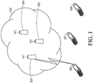
- FIG. 1 illustrates a communication system 100 including a network 102, TPs 103,104 and 105 (which may be implemented within eNBs or Remote Radio Heads (RRHs)), and user equipment (UE) 106,107 and 108.
- Various communication devices may exchange data or information through the network 102.
- the network 102 may be an evolved universal terrestrial radio access (E-UTRA) or other type of telecommunication network.
- E-UTRA evolved universal terrestrial radio access
- a network entity such as one of the TPs 103, 104, and 105, may assign a UE identifier (UEID) to one ore more of the UEs 106,107, and 108 when the UE first joins the network 102.
- UEID UE identifier
- a TP may be a distributed set of servers in the network 102. In another embodiment, a TP may correspond to a set of geographically collocated or proximal physical antenna elements.
- a UE may be one of several types of handheld or mobile devices, such as, a mobile phone, a laptop, or a personal digital assistant (PDA). In one embodiment, the UE may be a wireless local area network capable device, a wireless wide area network capable device, or any other wireless device.
- a TP may have one or more transmitters and one or more receivers. The number of transmitters at a TP may be related, for example, to the number of transmit antennas at the TP. Similarly, a UE may have multiple receive antennas communicating with one or more of the TPs. Each antenna port may carry signals to a UE from a TP and from the TP to the UE. Each antenna port may also receive these signals.
- a UE receives data from a TP in one or more layers (such as LTE spatial layers).
- the TP precodes the data to be communicated to the UE 106 onto the one or more layers, maps and transmits the resulting precoded data on one or more antenna ports.
- the effective channel (or beamformed channel) corresponding to a transmission layer may in general be estimated based on reference signals mapped to one or more antenna ports.
- the network 100 is capable of using Coordinated Multipoint (CoMP) techniques. CoMP will be described in more detail below.
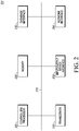
- FIG. 2 illustrates a possible configuration of a computing system to act as a TP(e.g., one or more of the TPs in FIG. 1 ).
- the TP may include a processor/controller 210, a memory 220, a database interface 230, a transceiver 240, input/output (I/O) device interface 250, and a network interface 260, connected through bus 270.
- the TP may implement any operating system, such as Microsoft Windows®, UNIX, or LINUX, for example.
- Client and server software may be written in any programming language, such as C, C++, Java or Visual Basic, for example.
- the server software may run on an application framework, such as, for example, a Java ® server or .NET ® framework.
- the processor/processor 210 may be any programmable processor.
- the subject of the disclosure may also be implemented on a general-purpose or a special purpose computer, a programmed microprocessor or microprocessor, peripheral integrated circuit elements, an application-specific integrated circuit or other integrated circuits, hardware/electronic logic circuits, such as a discrete element circuit, a programmable logic device, such as a programmable logic array, field programmable gate-array, or the like.
- any device or devices capable of implementing the decision support method as described herein may be used to implement the decision support system functions of this disclosure.
- the memory 220 may include volatile and nonvolatile data storage, including one or more electrical, magnetic or optical memories such as a random access memory (RAM), cache, hard drive, or other memory device.
- the memory may have a cache to speed access to specific data.
- the memory 220 may also be connected to a compact disc - read only memory (CD-ROM), digital video disc - read only memory (DVD-ROM), DVD read write input, tape drive, or other removable memory device that allows media content to be directly uploaded into the system.
- Data may be stored in the memory 220 or in a separate database.
- the database interface 230 may be used by the processor/controller 210 to access the database.
- the database may contain any formatting data to connect UE to the network 102 ( FIG. 1 ).
- the transceiver 240 may create a data connection with the UE.
- the I/O device interface 250 may be connected to one or more input devices that may include a keyboard, mouse, pen-operated touch screen or monitor, voice-recognition device, or any other device that accepts input.
- the I/O device interface 250 may also be connected to one or more output devices, such as a monitor, printer, disk drive, speakers, or any other device provided to output data.
- the I/O device interface 250 may receive a data task or connection criteria from a network administrator.
- the network connection interface 260 may be connected to a communication device, modem, network interface card, a transceiver, or any other device capable of transmitting and receiving signals from the network 106.
- the network connection interface 260 may be used to connect a client device to a network.
- the network connection interface 260 may be used to connect the teleconference device to the network connecting the user to other users in the teleconference.
- the components of the TP may be connected via an electrical bus 270, for example, or linked wirelessly.
- Client software and databases may be accessed by the processor/processor 210 from memory 220, and may include, for example, database applications, word processing applications, as well as components that embody the decision support functionality of the present disclosure.
- a TP FIG. 1
- Client and server software may be written in any programming language, such as C, C++, Java or Visual Basic, for example.
- program modules include routine programs, objects, components, data structures, etc. that perform particular tasks or implement particular abstract data types.
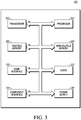
- FIG. 3 illustrates in a block diagram one embodiment of a telecommunication apparatus or electronic device to act as a UE(such as one or more of the UEs depicted in FIG. 1 ).
- the UE may be capable of accessing the information or data stored in the network 102.
- the UE may also support one or more applications for performing various communications with the network 102.
- the UE may be a handheld device, such as, a mobile phone, a laptop, or a personal digital assistant (PDA).
- PDA personal digital assistant
- the UE may be WiFi® capable device, which may be used to access the network 102 for data or by voice using VOIP.
- the UE may include a transceiver 302, which is capable of sending and receiving data over the network 102.
- the UE may include a processor 304 that executes stored programs.
- the UE may also include a volatile memory 306 and a non-volatile memory 308 which are used by the processor 304.
- the UE may include a user input interface 310 that may comprise elements such as a keypad, display, touch screen, and the like.
- the UE may also include a user output device that may comprise a display screen and an audio interface 312 that may comprise elements such as a microphone, earphone, and speaker.
- the UE also may include a component interface 314 to which additional elements may be attached, for example, a universal serial bus (USB) interface.
- USB universal serial bus
- the UE may include a power supply 316.
- one or more of the TPs and one or more the UEs may include one or more transmitters and one or more receivers.
- the number of transmitters may be related, for example, to the number of transmit antennas at the TP and UE.
- the TP and the UE may also have multiple antennas.
- a multiple antenna configuration on either a TP or a UE is generally supports MIMO communication.
- the TP 104 and the UE 106 generally communicate via uplink channels and downlink channels.
- the physical medium used is Radio Frequency (RF) signals, which are encoded using Orthogonal Frequency-Division Multiplexing (OFDM).
- the modulation scheme used by the TP 104 and the UE 106 differs depending on whether the signals are being sent in the uplink direction (which is the UE 106 to TP 104 direction) or the downlink direction (which is the TP 104 to UE 106 direction).
- the modulation method used in the downlink direction is a multiple-access version of OFDM called Orthogonal Frequency-Division Multiple Access (OFDMA).
- SC-FDMA Single Carrier Frequency Division Multiple Access
- orthogonal subcarriers are modulated with a digital stream, which may include data, control information, or other information, so as to form a set of OFDM symbols.
- the subcarriers may be contiguous or discontiguous and the downlink data modulation may be performed using quadrature phase shift-keying (QPSK), 16-ary quadrature amplitude modulation (16QAM), or 64QAM and typically downlink control modulation is QPSK although, other modulation schemes may be used too.
- QPSK quadrature phase shift-keying
- 16QAM 16-ary quadrature amplitude modulation
- 64QAM typically downlink control modulation is QPSK although, other modulation schemes may be used too.
- the OFDM symbols are configured into a downlink subframe (typically 1 millisecond duration) for transmission from the base station. Each OFDM symbol has a time duration and is associated with a cyclic prefix (CP).
- CP cyclic prefix
- a cyclic prefix is similar to a guard period between successive OFDM symbols in a subframe but, its primary function is to render the data transmitted on different subcarriers orthogonal upon application of a Fast Fourier Transform (FFT) in a receiver in a multipath fading channel.
- FFT Fast Fourier Transform
- the legacy Rel-8/9/10 control channel (PDCCH) is transmitted in the first few OFDM symbols at the beginning of the subframe and data is transmitted in the rest of the subframe on the LTE Uu downlink.
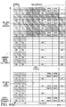
- FIG. 4 depicts a subframe 400 in the context of a time-frequency diagram.
- a vertical scale of the diagram depicts multiple blocks of frequency, or frequency bins (frequency subcarriers), of the subframe 400 that may be allocated for transmission.
- a horizontal scale of the diagram depicts multiple blocks of time (in units of OFDM symbols) of the sub-frame 400 that may be allocated.
- the subframe 400 comprises multiple resource blocks (RBs) such as Resource Block 0 (RB0), Resource Block 1 (RB1), Resource Block 2 (RB2), and Resource Block 3 (RB3).
- RB0 Resource Block 0
- RB1 Resource Block 1
- RB2 Resource Block 2
- RB3 Resource Block 3
- Each RB comprises 12 OFDM subcarriers over a time slot comprising seven (7) OFDM symbols for the normal CP case.
- the sub-frame duration is 1ms and it can comprise two time slots of 0.5ms duration each.
- each RB can be divided into multiple resource elements (REs).
- Each RE is a single OFDM subcarrier, or frequency bin, on a single OFDM symbol. It is to be noted that many frames and subframes may be transmitted from the TP 104 to the UE 106 and vice-versa, and that various channels may occupy slots in many sub-frames.
- RSs reference signals
- the references signals are transmitted by the TP 104 to the UE 106 to enable the UE 106 to perform some function. Two such reference signals will now be introduced.
- a demodulation reference signal (DMRS) (sometimes referred to as a UE-specific reference signal) is used by the UE 106 for channel estimation and demodulation for the EPDCCH.
- DMRS demodulation reference signal
- CSI-RS Channel State Information Reference Signal
- CSI channel-state information
- the CSI that the UE 106 reports includes a Channel Quality Indicator (CQI), a Pre-coding Matrix Indicator (PMI) and a Rank Indicator (RI).
- CQI tells the TP 104 information about the link adaptation parameters that the UE 106 can support at that time, taking into account the transmission mode, the receiver type of the UE 106, the number of antennas being used by the UE 106 and the interference being experienced by the UE 106.
- the CQI is defined by a sixteen entry table with Modulation and Coding Schemes (MCS).
- the UE 106 reports back to the TP 104 the highest CQI index corresponding to the MCS and TBS (Transport Block Size) for which the estimated received download transport Block Error Rate (BLER) (e.g., the ratio of blocks sent with transmission errors to total blocks sent) does not exceed 10%.
- PMI indicates to the TP 104 the codebook element that the TP 104 could use for data transmission over multiple antennas.
- RI is the recommendation of the UE 106 to the TP 104 for the number of layers to be used in spatial multiplexing.
- the RI can have, for example, values of 1 or 2 with a 2-by-2 antenna configuration and from 1 to 4 with a 4-by-4 antenna configuration.
- the RI is associated with one or more CQI reports.
- the UE 106 calculates CQI assuming a particular RI value which indicates an index of a Modulation / Coding Scheme (MCS) that could be received on the PDSCH with Block Error Rate (BLER) ⁇ 0.1; PMI, which indicates preferred precoding matrix for the PDSCH; and Rank Indicator (RI), which indicates number of useful transmission layers (its rank) for the PDSCH.
- MCS Modulation / Coding Scheme
- BLER Block Error Rate
- PMI which indicates preferred precoding matrix for the PDSCH
- Rank Indicator RI
- the TP 104 uses control signaling, including downlink (DL) signaling via DL control channel, and uplink (UL) signaling, via UL control channel.
- Downlink control signaling is carried by control channels.
- One such channel is the Physical Downlink Common Control Channel (PDCCH) which is located at the start of each downlink subframe (up to the first three OFDM symbols).
- Another, which is being introduced in LTE Rel-11, is the Enhanced Physical Downlink Control Channel (EPDCCH) which is located on one or more RB-pairs spanning both slots in the subframe .
- Each of these channels carries the downlink scheduling assignment, uplink scheduling grants, UL transmit power control commands, etc.
- the control region of a downlink subframe comprises the multiplexing of all EPDCCH or PDCCH bits into a single block of data which is subsequently processed to form complex modulated symbols. These symbols are then divided to form block of complex-valued symbols quadruplets known as a resource element group (REG). These REGs are then interleaved and cyclically shifted prior to EPDCCH or PDCCH resource mapping.
- REG resource element group
- the EPDCCH includes configuration information related to configuration of a control channel.
- EPDCCH supports increased control channel capacity, an ability to support frequency-domain ICIC, an ability to achieve improved spatial reuse of control channel resource, an ability to support beamforming and/or diversity, and/or an ability to operate in Multicast/Broadcast over a Single Frequency Network (MBSFN) subframes.
- a UE such as UE 106 ( FIG. 1 ) can receive the EPDCCH in a set of RBs that may span only a portion of the carrier bandwidth in frequency domain. As depicted in the subframe 400 of FIG. 4 , the UE 106 may expect to receive the EPDCCH in RB0 and RB1, i.e., RB-pairs spanning both slots of the subframe.
- An EPDCCH or PDCCH is transmitted on one or on an aggregation of consecutive Control Channel Elements (CCEs) or enhanced Control Channel Elements (eCCEs), where a CCE or eCCE corresponds to 9 Resource Element Groups (REGs) (it is to be noted that EPDCCH may also be referred to using the term CCE).
- CCEs Control Channel Elements
- eCCEs enhanced Control Channel Elements
- Each REG contains 4 Resource Elements (REs).
- Each control channel element includes time-frequency REs within the RBs of the EPDCCH or PDCCH OFDM symbol set.
- the EPDCCH or PDCCH carries scheduling assignments and other control information in form of downlink control information (DCI) messages.
- DCI downlink control information
- each instance of an EPDCCH has its own configuration.
- An EPDCCH configuration is described by a set of attributes.
- EPDCCH attributes may also be referred to using CCE terminPossible attributes of an EPDCCH include: eCCE size, eCCE aggregation level, localized transmission of the eCCEs, distributed transmission of the eCCEs, the transmission scheme of the EPDCCH, the SNR gain of the EPDCCH, set of RBs for EPDCCH, antenna ports for EPDCCH, number of antenna ports for EPDCCH, number of layers for EPDCCH, EPDCCH scrambling sequence (scrambling sequence for EPDCCH coded bits), DMRS sequence or DMRS scrambling sequence, initialization or portion of the initialization of the DMRS sequence, EPDCCH signature sequence (sequence used to modulate the DMRS sequence), modulation of the EPDCCH, and the EPDCCH to DMRS power boost (or the EPDCCH to any other reference signal
- the DMRS reference signal for an antenna port may be determined by a symbol-by-symbol product of an antenna port sequence and the DMRS sequence.
- the antenna port sequence may be selected from a set of orthogonal sequences which makes the DMRS signal for different antenna ports that share the same set of REs orthogonal.
- An example of two EPDCCHs having configurations that differ in one or more attributes is as follows: EPDCCH configuration #1 has 4 eCCEs, DMRS port #7, RBs ⁇ #5, #20, #35, #45 ⁇ , 0 dB power boost.
- EPDCCH configuration #2 has 8 eCCEs, DMRS port #7, RBs ⁇ #5, #20, #35, #45 ⁇ , 3 dB power boost. So, the two configurations differ in 2 attributes: # of eCCEs and power boost.
- the configuration of an EPDCCH is indicated by an EPDCCH configuration message.
- RSs labeled R7-R10 are allocated to DMRS (DMRS REs).
- DMRS REs DMRS REs
- RSs corresponding to antenna ports 7 and 8 are multiplexed using Code Division Multiplexing (CDM) or other scheme and are mapped to the same REs in time and frequency domain.
- the subframe can also include other RSs such as cell-specific reference signal (CRS), positioning reference signal (PRS), primary synchronization signal (PSS) and secondary synchronization signal (SSS) that are distributed in the control regions and/or user data regions of the sub-frame. These other RSs may be present but are not necessarily used for demodulation of received signals by a UE in an LTE-A communication system.
- the other RS may include the CSI-RS, muted (or zero-power) CSI-RS where the UE can assume and zero transmission power on the RS REs that may be useful for interference measurements, improving channel measurements on CSI-RS from other TPs etc.
- the CSI-RS is typically not used for demodulation purposes and may be present in occasional sub-frames, i.e., the sub-frame periodicity, sub-frame offset (relative to a radio frame boundary), and the number of CSI-RS antenna ports are configurable via higher layer signaling.
- CSI-RS typically occupy REs that are not occupied by CRS, potential DMRS, etc.
- RSs corresponding to an antenna port can be allocated to a RE pair in user data regions, and more particularly to one of the RE pairs associated with OFDM symbols. For example, pairs of adjacent DMRS RE labeled as R7/8 may be allocated to antenna port 7 and antenna port 8 and, pairs of adjacent DMRS RE labeled as R9/10 may be allocated to antenna port 9 and antenna port 10.
- the RS for R7 and R8 can be code-division multiplexed using orthogonal Walsh codes.
- the RS for R9 and R10 can be code-division multiplexed using orthogonal Walsh codes.
- the UE may receive a message containing one or more CSI-RS-resource configurations through higher-layer signaling. For example, UE might receive CSI-RS-resource configuration information from the network via RRC signaling. The RRC layer in the UE would then provide the CSI-RS configuration information to the physical layer in the UE (e.g., "higher layer signaling")
- a CSI-RS-resource configuration includes information that indicates the resources used by the CSI-RS (which will be referred to as CSI-RS-resources).
- the CSI-RS are typically transmitted only in some DL subframes and not all. In general, the CSI-RS-resource information uniquely identifies the time-frequency resources to which the CSI-RS are mapped.
- each CSI-RS-resource may represent transmission from multiple TPs (such as when two or more TPs are involved in Joint Transmission (JT) or Dynamic Point selection (DPS)). Additionally, each CSI-RS-resource may have one or more physical antenna port associated with it. These possibilities hold true for the CSI-RS. There may be a one-to-one correspondence between CSI-RS and TPs, one-to-many, or one CSI-RS per physical antenna port.
- the UE 106 can monitor EPDCCH in a set of RBs ( FIG. 4 ) (EPDCCH RB set) that may span only a portion of the carrier bandwidth in frequency domain. Further, the UE 106 may monitor the EPDCCH in only those time symbols in the subframe that are distinct from the time symbols corresponding to PDCCH. For example, the UE 106 can monitor PDCCH across the entire carrier bandwidth in frequency domain and in time symbols in the time domain (i.e., there are two control symbols in the example). The UE 106 can monitor EPDCCH in one (e.g.
- RB0 RB0
- RB0 may be defined to cover only the non-PDCCH region resources, i.e., excluding the OFDM symbols assigned for PDCCH.
- RB0 may be defined to start from a pre-determined symbol and occupy the remaining symbols in the slot. The pre-determined symbol may be signaled to the UE via PDCCH or higher layer signaling (e.g., RRC or MAC signaling).
- the UE 106 can monitor several EPDCCH candidates or monitor for the enhanced control channel. Monitoring implies attempting to blindly decode one or more EPDCCH candidates (in this example blind decoding can be attempted for each of the several EPDCCH candidates). It is noted that the DMRS required for EPDCCH decoding may be sent only when EPDCCH is sent, unlike the CRS which is sent always in every subframe (or some portion of the subframes) even if PDCCH is not sent.
- the set of EPDCCH or PDCCH candidates to be monitored by UE 106 can also be defined in terms of search spaces.
- FIG. 5 shows an example of how search spaces may occupy different portions of the time-frequency domain.
- search regions there are three search spaces (search regions): Region 1, which originates from a first TP (TP 1); Region 2, which is shared by TP1 and a second TP (TP2); and Region 3, which originates from TP2. These three regions are located in the same subframe.
- an EPDCCH search space S k L at aggregation level L can refer to a set of EPDCCH candidates where each candidate in the search space has L aggregated eCCEs.
- the same or different aggregation levels may be supported.
- a set of aggregation levels that the UE 106 assumes for EPDCCH monitoring also may vary between subframes or between slots in a same subframe or between different subframe types (for example, a normal subframe vs. an MBSFN subframe). More generally, a set of aggregation levels that the UE assumes for EPDCCH monitoring can vary between a first time period and a second time period.
- the EPDCCH candidates that UE 106 monitors can be further divided into a set of common search space candidates , and a set of UE specific search space candidates.
- Common search space candidates may be monitored on a EPDCCH RB set that is broadcast to all the UEs in the coverage area of the serving TP(s). For example, in LTE, this information can be broadcasted in a Master Information block (MIB) or in a System Information Block (SIB).
- MIB Master Information block
- SIB System Information Block
- the UESS candidates may be monitored on an EPDCCH RB set that is signaled to the UE via UE specific higher layer signaling.
- the TP 104 determines an EPDCCH format to be transmitted to the UE 106, creates an appropriate DCI and attaches a CRC.
- the CRC is then masked with an RNTI according to the usage of the EPDCCH. If the EPDCCH is for a specific UE, the CRC will be masked with a UE unique identifier, for example a Cell-Radio Network Temporary Identifier (C-RNTI).
- C-RNTI Cell-Radio Network Temporary Identifier
- the CRC will be masked with a paging indication identifier, i.e., Paging-RNTI (P-RNTI). If the EPDCCH contains system information, a system information identifier, i.e., a system information-RNTI (SI-RNTI) will be used to mask the CRC.
- P-RNTI Paging-RNTI
- SI-RNTI system information-RNTI
- the TP 104 may only inform the UE 106 of the number of OFDM symbols within the PDCCH region of a subframe. Details pertaining to the specific RBs used for transmission of EPDCCH from TP 104 may or may not be provided to UE 106.
- the UE 106 may find its EPDCCH by monitoring a set of EPDCCH candidates in every subframe. This is referred to as blind decoding of EPDCCH.
- the UE 106 de-masks each EPDCCH candidate's CRC using its Radio Network Temporary Identifier (RNTI). If no CRC error is detected, the UE 106 considers it as a successful decoding attempt and reads the control information within the successful EPDCCH candidate.
- RNTI Radio Network Temporary Identifier
- the DCI undergoes channel coding: addition of a CRC attachment followed by convolutional coding and rate matching according to EPDCCH format payload size, aggregation level, etc.
- the coded DCI bits i.e. the EPDCCH payload, are then mapped to enhanced Control Channel Elements (eCCEs) according to the EPDCCH format.
- eCCEs enhanced Control Channel Elements
- These coded bits are then converted to complex modulated symbols after performing operations including scrambling, QPSK modulation, layer mapping and precoding. Finally, the modulated symbols are mapped to physical Resource Elements (REs).
- REs physical Resource Elements
- the UE 106 may perform blind decoding of the EPDCCH payload as it is not aware of the detailed control channel structure, including the number of control channels and the number of eCCEs to which each control channel is mapped. Multiple EPDCCHs can be transmitted in a single subframe which may and may not be all relevant to a particular UE.
- the UE finds the EPDCCH specific to it by monitoring a set of EPDCCH candidates (a set of consecutive eCCEs on which EPDCCH could be mapped) in every subframe.
- the UE 106 uses its Radio Network Temporary Identifier (RNTI) to try and decode candidates.
- the RNTI is used to de-mask an EPDCCH candidate's CRC. If no CRC error is detected the UE 106 determines that the EPDCCH carries the control information intended for the UE 106.
- RNTI Radio Network Temporary Identifier
- the downlink control channel information can be a downlink assignment or an uplink grant or an uplink power control command.
- a downlink assignment may include one of more of a downlink resource allocation information, DL HARQ information, DL MIMO information, power control information, user identifier or RNTI, etc.
- the UL grant may include uplink resource allocation information, uplink HARQ information, uplink MIMO information, power control commands, user identifier or RNTI, etc.
- the DCI payload is convolutionally encoded, and then rate-matched and mapped to resource elements based on the search space, where the number of resource elements may be determined based on the aggregation level and CCE size (or eCCE size).
- uplink grants are only used for causing a UE to report specific control information such as channel quality information (CQI) or channel state information (CSI). In general other control information could be send such as UE identify information, buffer occupancy information, power control state information.
- CQI channel quality information
- CSI channel state information
- Such an uplink grant type will be referenced hereon as a "CQI only" uplink grant.
- the UE 104 engages in Radio Link Monitoring (RLM). Further operations of the UE 106 are described in the methods below.
- RLM Radio Link Monitoring
- the UE Layer 1 In Release-8/9/10 of 3GPP LTE, the UE Layer 1, such as or the physical layer, conducts RLM, for the purpose of detecting radio link failure (RLF) and radio link recovery. This is done by indicating a radio problem detection status or radio link quality to higher layers based on processing CRS.
- RLM may be based on TP-specific reference signals such as DMRS or CSI-RS.
- non-Discontinuous Reception (non-DRX) mode operations such as when the UE is not in sleep mode
- the UE in every radio frame checks the quality, measured over a time period, against thresholds (also known Qout and Qin) defined implicitly by relevant requirements for detecting out-of-sync (OOS) and in-sync (IS) conditions, where the term "sync" is synchronization.
- OOS out-of-sync
- IS in-sync
- the UE may be handed over to another serving TP(s) (based on measurements provided by the UE to the TP or network-aided measurements).
- the UE cannot be handed over to a different serving TP(s). In such cases, a radio link failure occurs and radio link recovery procedure is considered useful.
- the criteria for declaring that an RLF has occurred are defined based on whether or not a reference PDCCH Block Error Rate (BLER) ⁇ define BLER ⁇ is achieved for a particular downlink control channel configuration.
- BLER Block Error Rate
- the OOS is reported to the higher layers from the lower layers if a hypothetical or reference PDCCH BLER becomes greater than 10% assuming the transmission of a Downlink Control Information (DCI) Format 1A at an eight CCE aggregation level, which, for example, corresponds to a small payload size Downlink (DL) assignment (used for scheduling data or broadcast control transmissions) with the highest code protection (due to using eight CCEs where eight is the maximum that can be assigned for a DCI).
- DCI Downlink Control Information
- An IS condition is reported if the hypothetical or reference PDCCH BLER drops below 2% assuming the transmission of a DCI Format 1C (with a certain different payload size) at a 4 CCE aggregation level, such as the downlink control message associated with (for scheduling) the transmission of a paging message or system information message (which may typically be broadcast information).
- a DCI Format 1C with a certain different payload size
- the TP can further configure the UE to monitor the radio link quality in only a subset of sub-frames. Based on the OOS and IS events, if it is determined that the radio link quality is poor, Radio Link Failure (RLF) may be declared.
- RLF Radio Link Failure
- the LTE Rel-8 UE procedure for RLM does not involve network signaling (i.e., UE RLF is deduced by the network by suspension of UE UL transmission after the expiry a timer).
- UE sending an indication that an RLF has occurred can lead to measures for improving the EPDCCH link by the eNB such as to re-configuration of EPDCCH configuration such as changing of antenna precoding coefficients associated with DMRS ports, EPDCCH power boosting, changing of the set of RBs configured for EPDCCH, etc. Therefore, UE can indicate that an RLF has occurred (or near occurrence) to the eNB.
- the UE can suspend UL until T310 expires and then attempt RRC connection re-establishment if the EPDCCH is not configured before the timer expires. Alternatively, the UE can continue transmission on the UL until T310 timer expires and stop UL transmission if EPDCCH is not re-configured and the timer expires.
- the ACK/NACK PUCCH resources available to the UE to transmit uplink signals can be configured via higher layer signaling. Thus, if such resources are available, the UE may use those resources for sending an indication to the eNB that an RLF has occurred.
- the UE 106 can use a different method for OOS/IS condition based on the type of control channel the UE 106 is monitoring. For example, when the UE 106 monitors the PDCCH, it can use the Cell-specific Reference Signal (CRS) for RLM, and when the UE 106 is configured to monitor the EPDCCH, it can use the EPDCCH DMRS or CSI-RS for RLM.
- CRS Cell-specific Reference Signal
- the configuration of the resources used for EPDCCH can be done via higher-layer signaling.
- the synchronization condition can be estimated based on at least one of a set of configured Virtual Resource Blocks (VRBs) (virtual resource block set) on possibly a set of configured subframes (or a subframe subset).
- the synchronization condition can be an out-of-synchronization condition or an in-synchronization condition.
- a first synchronization condition can be estimated based on antenna port set configuration for EPDCCH transmission. For example, an EPDCCH configuration message can indicate that a DMRS antenna port 7 is used or that a DMRS antenna port set ⁇ 8,10 ⁇ with rank 2 transmission (or transmit diversity scheme) is used.
- a second synchronization condition can also be estimated based on Energy Per Resource Element (EPRE) information relating to EPDCCH transmission.
- EPRE Energy Per Resource Element
- the EPDCCH configuration message can include the range of EPDCCH power boosts or de-boosts that the eNB intends to use relative to for example, CRS or CSI-RS, such as by signaling a ratio of the EPDCCH EPRE to CRS EPRE or a EPDCCH EPRE to CSI-RS EPRE (or to any other reference signal) for EPDCCH.
- the synchronization condition can also be estimated based on assuming at least one of a hypothetical or a reference downlink assignment or an uplink grant. Further assumptions for estimating the second synchronization condition can be acquired via configuration signaling or higher layer signaling.
- the assumptions for the second synchronization condition can include enhanced CCE size, enhanced CCE aggregation level, and other assumptions or attributes of the EPDCCH.
- the second synchronization condition (OOS) associated with the radio link that is further based on the first type of reference signal can be further estimated.
- OOS the second synchronization condition
- an out-of-synchronization condition of the radio link can be determined if the first synchronization condition is out-of-synchronization and the second synchronization condition is out-of-synchronization.
- the UE 106 can estimate a synchronization condition based on the received second type of reference signal and based on at least one attribute of the control channel.
- the attribute of the control channel can be received from the EPDCCH configuration signaling, can be separate signaling, can be set according to a specification, such as 1A/6 eCCE, 1C/5 eCCE, or other enhanced Control Channel Elements (eCCE), or it can be otherwise determined. Since the eCCE size may be variable based on the subframe configuration, a reference eCCE size used for estimation of the synchronization may be signaled by the eNB either implicitly or explicitly or may be derived by the UE implicitly or explicitly.
- an eCCE size may vary from 18 Resource Elements to 144 Resource Elements and in another example, an eCCE size may be defined as the number of resource elements available for an ePDCCH in one Resource Block pair or a portion of a RB-pair.
- the UE 106 can estimate a synchronization condition based on the received second type of reference signal, such as CSI-RS and based on the first type of reference signal, such as DMRS.
- the UE 106 can estimate a synchronization condition based on the received second type of reference signal, such as the CSI-RS, and at least one attribute of the first type of control channel, such as the EPDCCH and also based on a third type of reference signal, such as a Cell-specific Reference Signal (CRS), and at least one attribute of a second type of control channel, such as a legacy Physical Downlink Control Channel (PDCCH).
- the synchronization condition can be an out-of-synchronization condition or an in-synchronization condition.
- the at least one attribute of the control channel can be a reference enhanced control channel element (eCCE) size, can be a reference aggregation level for aggregation of eCCEs, can be a localized or a distributed transmission of the eCCEs, can be a reference transmission scheme associated with the control channel or the eCCE, can be a reference search space associated with the control channel, or can be any other attribute.
- eCCE reference enhanced control channel element
- the UE 106 cansend an output from a current layer to a higher layer based on at least one of the estimated synchronization conditions. For example, the output can signal the UE 106 to stop receiving second control channel or to switch control channels. Sending the output can also include sending an estimated condition, can include sending an channel quality indicator, can include sending information regarding the synchronization condition, or can include sending any other output based on an estimated condition.
- the UE 106 can send an output by sending an indicator to a base station via the transceiver 302 based on the output sent to the higher layer. Both layers may be inside the processor 304 and the UE can also send an output from one layer inside the processor 304 to another layer inside the processor 304.
- a synchronization condition can be an OOS or an IS condition. Indications of these conditions can be used by a higher layer such as the RRC layer or Layer 3 to trigger a radio link monitoring procedure.
- a higher layer such as the RRC layer or Layer 3
- Indications of these conditions can be used by a higher layer such as the RRC layer or Layer 3 to trigger a radio link monitoring procedure.
- a number of OOS indications such as based on a N311 counter
- a T310 timer can be started. If no IS indications are received before T310 expires, the Layer 3 can declare a Radio Link Failure and can suspend uplink transmissions.
- the Layer 3 can declare a Radio Link Recovery and the UE 106 can resume normal operation.
- the value of the timers and counters may vary based on the RLM technique being used in the UE or based on eNB configuration through higher-layer signaling.
- the system depicted in FIG. 1 in an embodiment of the invention may employ CoMP.
- CoMP techniques enable semi-static or dynamic coordination or transmission and reception with multiple geographically separated TPs.
- One of the problems that CoMP addresses is the problem of maintaining a high data rate at distances that are furthest away from the TP the UE is connected to.
- the edges of the TPs coverage area are the most challenging when the UE is within signaling range of neighboring TPs that lack coordination with the serving TP(s). Not only is the signal lower in strength because of the distance from the TP, but also interference levels from neighboring TPs are likely to be higher as the UE is closer to them.
- CoMP When implemented using 4G LTE, CoMP employs two major transmission schemes: Joint Transmission (JT) and Coordinated Scheduling or Beamforming (CS/CB).
- JT Joint Transmission
- CS/CB Coordinated Scheduling or Beamforming
- JT data for a UE is available at more than one point and there is coordination between multiple TPs that are simultaneously transmitting to or receiving from UEs.
- CS/CB data for an UE is only available from one TP and a UE receives a signal from that single TP over an time-frequency resource (such as a RB) but user scheduling/beamforming decisions are made with coordination among multiple TPs.
- time-frequency resource such as a RB
- the UE When using DMRS, the UE does not need to know which TPs or cells are involved in a transmission, assuming the TPs that are coordinating with one another use the same DMRS sequence on the DMRS antenna ports to serve the UE (which the UE is assigned or indicated to use for demodulation purpose).
- the UE is aware only of a unique or effective or composite channel, formed by the sum of the channels between each of the TPs involved in the transmission and the UE.
- transmissions by one or more TPs to the UE, as well as the members or points of the coordinating group or cooperating set of TPs may be changed without any additional signaling to the UE.
- a CSI-RS on a particular CSI-RS antenna port is specific to a particular TP (e.g., specific to a TP) and are generally not precoded. This allows the UE to estimate and report the CSI relating to neighboring TPs or cells or particularly CSI relating to a CSI-RS resource which may be configured with CSI-RS antenna ports, one or more of which are used for transmitting CSI-RS from neighboring TPs.
- the set of TPs (or CSI resources associated with TPs) about which the UE performs CSI measurement is referred to as the CoMP measurement set.
- the UE When the UE actually reports CSI (e.g., to the serving TP(s)), it may only report CSI on a subset of the CoMP measurement set. This disclosure will also refer to a "CoMP subset," which is a selected subset of the CoMP measurement set. Its purpose will be apparent below.
- the UE may autonomously down-select to report CSI on CoMP subset, be configured by TP to report CSI for CoMP subset or a combination thereof.
- DPS Dynamic point selection
- muting Data transmission from one point (within the CoMP cooperating set) in a time-frequency resource.
- the transmitting/muting point may change from one subframe to another including varying over the RB pairs within a subframe. Data is available simultaneously at multiple points.
- DCS Dynamic cell selection
- SSPS Semi-static point selection
- a hybrid category of JP and CS/CB may be possible.
- data for a UE may be available only in a subset of points in the CoMP cooperating set for a time-frequency resource but user scheduling/beamforming decisions are made with coordination among points corresponding to the CoMP cooperating set.
- some points in the cooperating set may transmit data to the target UE according to JP while other points in the cooperating set may perform CS/CB.
- CoMP transmission points may include one or points in the CoMP measurement set in a subframe used for transmitting data for a certain frequency resource.
- a single point in the CoMP measurement set is the CoMP transmission point in a subframe for a certain frequency resource.
- this CoMP transmission point can change semi-statically within the CoMP measurement set.
- Each eNB provides communication services to UEs in a geographic/ site area which may be sectorized in to one or regions referred to as a cell or intra-site cell.
- a cell or intra-site cell For example, an eNB covers 3 cells in scenario 800, 802 with each cell can be considered as having a TP.
- the first scenario 800 is a homogeneous cellular network with intra-site CoMP.
- a central entity (such as the eNB or an entity within the eNB such as a scheduler) can control or coordinate the transmissions from the TPs of each of the three cells within its geographic area or coordination area which is referred to as intra-site CoMP.
- the second scenario 802 is a homogeneous network with high transmission power Remote Radio Heads (RRHs).
- RRH may be passive amplifiers, or each may contain full signal processing capability (i.e., a transceiver).
- RRH can also be referred to as a sub-base station, remote antenna unit, Remote Radio Unit (RRU) or other terminology known in the art.
- the geographic coverage area of a RRH may be sectorized in to one or cells, with each cell can be considered as having a TP.
- the central entity can coordinate nine cells as a baseline.
- the designer of a system according to the second scenario may choose between 3, 19, 21 cells as a potential optional value.
- the third scenario, depicted by 804, is a heterogeneous network with low power RRHs (or low power nodes (LPN)) within the macrocell coverage.
- the macrocell may be an eNB intra-site cell and may be considered as being associated with a TP.
- the geographic coverage area of each low power RRH in scenario 804 may be generally referred to as a subcell, and the RRH (with no sectorization) can be considered as being a TP.
- the RRHs are geographically (or spatially) separated and controlled by the eNB of the macrocell.
- the eNB can be considered as using a Distributed Antenna system (DAS) with the macrocell TP and each RRH associated with one or more antenna ports in the DAS.
- DAS Distributed Antenna system
- transmission/reception points created by the RRHs have different cell IDs as the macro cell.
- the coordination area includes: 1 cell with N low-power nodes as starting point, and can include 3
- the fourth scenario also depicted by 804, in a cellular network having low power RRHs within the macrocell coverage, similar to third scenario except the transmission/reception points created by the RRHs have the same cell IDs as the macro cell.
- the coordination area includes one cell with N low-power nodes as starting point and can include three intra-site cells with 3*N low-power nodes.
- the TP 104 broadcasts a CSI-RS using a CSI-RS resource to the UE 106.
- the TP 104 also transmits EPDCCH search information to the UE 106.
- the TP 104 transmits data indicating the RBs that are to be monitored by the UE via dedicated or UE-specific RRC signaling or via a Broadcast Control Channel (BCCH) such as a Physical Broadcast Channel (PBCH) that the UE 106 receives.
- BCCH Broadcast Control Channel
- PBCH Physical Broadcast Channel
- the PBCH contains a Master Information Block that indicates which RBs the UE 106 should search in order to locate the EPDCCH that is intended for it.
- the TP 106 may transmit the EPDCCH search information in a System Information Block (SIB) of a BCCH which is contained in the Physical Downlink Shared Channel (PDSCH).
- SIB System Information Block
- the UE 106 may receive more than one BCCH. For example, if the UE 106 is in broadcast range of a first TP and a second TP, the UE 106 will receive a first BCCH and a second BCCH.
- the TP 104 transmits data that associates each CoMP subset with the identity of a CoMP transmission scheme. For example, subset 1 (having CSI resource(s) associated with 2 TPs) is associated with JT, subset 2 (having CSI resource(s) associated with 3 TPs) is associated with DPS. Any given subset (e.g., subset 2 in the previous example) may be the same as the full CoMP measurement set.
- the UE 106 can use the mapping as an input into its calculation of the hypothetical or reference EPDCCH BLER.
- the TP 104 transmits to the UE 106 a mapping between RB search regions, CoMP subsets and CoMP transmission schemes.
- the UE 106 can use this mapping as an input into its calculation of hypothetical BLER towards OOS, IS or CSI (CQI/PMI/RI) determination.
- the TP 104 can send a signal indicating that RB region to CoMP subsets and CoMP transmission scheme mapping as follows:
- Each CoMP subset has one or more CSI-RS-resources associated with it.
- the association between a CSI-RS-resource and a set of TPs need not be conveyed to the UE for CQI/PMI/RI reporting or RLM.
- the TP 104 transmits information regarding which CSI-RS antenna ports are "quasi" co-located (e.g., the information may include which CSI-RS ports within each CSI-RS-resource are quasi collocated and which CSI-RS ports across different CSI-RS resources are quasi collocated or from quasi collocated TPs).
- the UE may assume that large-scale properties of the signal received from the first antenna port can be inferred from the signal received from the other antenna port.
- the "large-scale properties" consist of some or all of Delay spread, Doppler spread, Frequency shift, Average received power, Received Timing.
- the EPDCCH search space for the UE 106 may comprise EPDCCH candidates that are associated with CSI-RS-resources. While in general, the UE 106 does not need to know which EPDCCH candidate is associated with which TP, if the UE is performing CQI/PMI/RI reporting or RLM, then it should assume transmission over a certain RB region is associated with one or more CSI-RS-resources. In one embodiment, the UE 106 assumes that each CSI-RS-resource is transmitted by or associated with a single TP, and therefore that the number of TPs that may coordinate for EPDCCH transmission on EPDCCH candidates in a search region is the number of CSI-RS-resources associated with that search region.
- the UE 106 may receive an interference measurement resource (IMR) set configuration from the serving TP(s) through higher-layer signaling (e.g., from a higher layer to the physical layer).
- This configuration can be one or more of a zero power CSI-RS resource and a non-zero power CSI-RS resource.
- IMR could be just a single zero-power CSI-RS configuration (comprising 4 CSI-RS ports).
- an IMR could be a configuration similar to Rel-10 CSI-RS resource configuration but with additional assumptions on (i) the set of RBs applicable to each IMR, (ii) whether TPs within the CSI measurement set must be considered to be isotropic interferers, etc.
- IMR is configured by the serving TP(s) through higher-layer signaling.
- Each IMR configuration set can be associated with a CoMP subset.
- each of the three search regions has a CoMP transmission schemes in Fig. 1 maps to a respective IMR resource set (IMRS).
- IMRS IMR resource set
- the TP 104 can transmit the mapping of a IMRS, a CoMP transmission scheme, and a CoMP subset to each search region.
- the TP 104 can transmit the following mapping to the UE 106:
- IMRS-related information may not be necessary for DMRS-based demodulation. However, it may be necessary for CQI/PMI/RI reporting and RLM comprising OOS/IS determination.
- the TP 104 may, in an embodiment of the invention, send a subset of the possibilities, i.e., a subset of the mapping (applicable to CSI reporting) and ask the UE 104 to perform RLM on that subset.
- the subsets can be different for OOS and IS to allow for the possibility that common control may be transmitted based on creating a Single Frequency Network (SFN) type area while dedicated control may use CoMP JP methods (based on the available feedback).
- SFN Single Frequency Network
- dedicated control may use CoMP JP methods (based on the available feedback).
- all of the TPs within each cell i.e., macro TP and 3 RRH or LPN TPs
- share the same cell ID Physical Cell ID, PCID
- CRS sequence is based on PCID
- PCID Physical Broadcast Channel
- the common control may be transmitted on PDCCH and PDSCH where the UE is expected to use CRS for demodulation.
- user-specific or dedicated control may be transmitted over EPDCCH where the UE must use DMRS for demodulation.
- the UE 106 evaluates OOS and IS conditions for each hypothesis. For example, using the IMRS, CoMP transmission scheme, CoMP subset to search region mapping discussed above, the UE 106 can determine the OOS / IS condition for each search region. There can be multiple hypotheses corresponding to one or more of the CoMP transmission scheme, IMRS and CoMP subset to search region mapping. A search region may have multiple hypotheses corresponding to different CoMP transmission scheme, IMRS and CoMP subset combinations. Hypothetical BLER can be determined for each of the different hypotheses. Suitable hypothetical BLER thresholds can be applied based on the approach taken.
- CoMP JT schemes One aspect of CoMP JT schemes is that a single codebook could be spread across multiple TPs (e.g., distributed beamforming from multiple TPs using same PRB pairs, same eCCE start index, aggregation level, same DMRS port, etc.) is possible (e.g., in FIG. 4 , Region 3 comprising RB4-5) is possible.
- the UE would attempt to decode EPDCCH in a UE-transparent manner in the configured search space based on DMRS. For this case, the UE would need to correctly hypothesize that one of the possible transmission schemes for EPDCCH is CoMP distributed beamforming (DBF) and compute the hypothetical BLER based on CSI-RS appropriately.
- DBF CoMP distributed beamforming
- the UE 106 does not necessarily have all the information it needs. For example, the UE may need to know whether the JT can virtualize CSI-RS antenna ports in any arbitrary manner or whether the UE can assume the JT is restricted to using only certain codebooks for EPDCCH transmission (e.g., the JT only uses LTE Release 10 codebooks such as 8x1 or 8x2 or 8xN for higher rank N > 2 codebooks).
- the UE designates a subset of all of the possible codebooks as being the only ones used. In other words, the UE assumes that only certain codebooks are used by the TPs involved in JT. For example, the UE could assume that only Rel-10 codebooks can be used.
- new codebooks can be defined for Rel-11.
- the UE would then determine the aggregate CQI for the best case (i.e., compute PMI corresponding to maximum aggregate CQI and use this PMI for computing hypothetical BLER).
- the UE computes aggregate PMI F ⁇ 12 across two TPs, TP1 and TP2, which are configured as one CSI-RS-resource per TP or as a single CSI-RS-resource comprising CSI-RS from two TPs.
- F ⁇ 12 arg max F ⁇ C 12 CQI F R , where C 12 is the joint codebook (e.g., Rel-10 8x2 or 8x1 or 8xN, N>2 codebook) and R is the interference covariance matrix.
- the interference covariance matrix may be determined for example based on IMRS configured over Region 3 where JT from TP1 and TP2 can occur.
- the computed aggregate PMI F ⁇ 12 is used to find the max and min hypothetical BLER estimates for the OOS and IS payload formats.
- the MCS table (for the Physical Downlink Shared Channel or PDSCH) covers the code rate range [ ⁇ 0.12, 1] while PDCCH code rate can extend below 0.05. There is therefore a gap between the current MCS table (optimized for PDSCH) and the range of CQI necessary for accurate dimensioning of aggregation resources (particularly if the EPDCCH is made to work all the way up to -12 or -13 dB).
- the MCS table can be augmented to cover all the code rates that are of interest for EPDCCH transmission.
- Such an extension of the MCS table may lead to CQI reporting over the extended region targeted towards EPDCCH MCS levels.
- the extended MCS table approach will allow the TP to optimize the appropriate aggregation level and power boost needed to meet a certain target EPDCCH BLER for each UE.
- the extended MCS table can be defined to include code rate points that correspond to 1dB SNR steps (applicable to say, 10% BLER or 1% BLER).
- a first table 700 expresses the code rate range of the PDCCH.
- the first table 700 is indexed by code rate (ratio of number of information bits in a TB to number of channel bits in a PRB).
- the values on the right represent the code rate in terms of dB (e.g., the SNR corresponding to 10% BLER when a packet of the corresponding code rate is received on a certain reference channel). As shown, the code rate ranges from 0.12 to 1.
- a second table 702 expresses the code rate range of EPDCCH.
- the switch from the first table to the second table can be performed based on a CSI-based event trigger such as:
- a rescue or distress signal may be implemented for EPDCCH RLF.
- the distress signal may be sent over an uplink indicator channel, such as RACH, modified SR, or contention-based PUSCH.
- the PDCCH has both CSS and UESS and the EPDCCH has both CSS and UESS, but the blind decodes are split between the two.
- the UE may be monitoring only the CSS on the PDCCH, while monitoring the CSS and UESS on the EPDCCH.
- the UE may be monitoring only the CSS on the PDCCH and only the UESS on the EPDCCH with the blind decodes being split between the two.
- the UE may detect that the EPDCCH quality is unacceptable (e.g., BLER for EPDCCH DCI with maximum CCE possible in the configured RBs exceeds a threshold).
- the UE may detect that there is a radio link problem onset (i.e., an intermediate state where link quality degradation is detected but, a RLF is not declared yet) for example, based on detecting N311 OOS indications, N311 corresponding to a first threshold.
- the UE may transmit an SR or RACH (suitably augmented) to convey to the TP that the EPDCCH is unreliable and that TP should schedule on PDCCH if possible.
- the network based on explicit or implicit indication (RLPO), would adjust search space provisioning (number of blind decodes) for the EPDCCH and the PDCCH.
- the TP would transmit an UL grant in CSS or UESS of PDCCH in response to the received SR or RACH.
- the UE may use the grant to transmit radio condition information to the network in order to assist the network to identify new EPDCCH configurations to be used for the UE.
- the UE may continue to monitor the UESS of the PDCCH in order to receive downlink and uplink grants until instructed by the network to resume monitoring the EPDCCH.
- the UE may send multiple transmissions of the distress signals or cease transmission on detection of a control channel transmission targeted to the UE on the PDCCH or on the EPDCCH CSS.
- the UE may be configured to monitor the PDCCH in case of distress on a second carrier distinct from the carrier transmitting the EPDCCH.
- the UE may detect that the quality of one type of control channel (e.g. EPDCCH) is becoming unacceptable and it may attempt to indicate, for example, via a distress signal such as SR (modified resources) or RACH (message length or format or physical resources modified to accommodate implicit or explicit signaling), to the network so that the network can communicate with the UE using the second type of control channel (e.g. PDCCH).
- a distress signal such as SR (modified resources) or RACH (message length or format or physical resources modified to accommodate implicit or explicit signaling)
- the UE may be configured with dedicated preambles to be used for the RACH transmission.
- this UL signaling may be used as a trigger to re-configure the UE's first control channel (e.g., increasing the maximum aggregation-level in EPDCCH).
- RACH/SR resources can be used to indicate different types of distress signals.
- RACH preambles used for distress signalling can be pre-assigned. If CSS is implemented in the PDCCH, the SR or RACH response will be on the PDCCH.
- the UE may transmit a RACH to convey to the TP that the EPDCCH is unreliable and the TP must either schedule on PDCCH (i.e. the user-specific search space or common search space or both) or change the configuration of EPDCCH.
- RACH can use one of the 4 preamble formats (Preamble Format 0,1, 2, 3) for Frame Structure 1 (FDD) and five preamble formats (Preamble Format 0,1, 2, 3, 4) for Frame Structure 2 (TDD).
- the PRACH (Physical Random Access Channel) configuration index determines the random access configuration that specifies the time location, where the UE may transmit PRACH, specifically, the system frame (even or odd or any) and subframe number. Additional higher-layer signaling can specify the frequency location of the PRACH, the RACH root sequence used for generating the Zadoff-Chu sequence that is used in the PRACH signal and a cyclic shift associated with the Zadoff-Chu sequence.
- the RACH root sequence may be broadcast by the TP or be predetermined.
- a subset from the set of existing preamble formats, PRACH configuration indexes (and time location of PRACH), frequency location of PRACH, cyclic shifts and RACH root index can be reserved in a pre-determined way (i.e. specified in the 3GPP standard).
- a new set of preamble formats, PRACH configuration indexes (and time location of PRACH), frequency location of PRACH, cyclic shifts and RACH root index can be allocated for this purpose leading to the definition of a enhanced RACH (eRACH).
- eRACH enhanced RACH
- the UE may transmit a SR to convey to the TP that the EPDCCH is unreliable and the TP must either schedule on PDCCH (i.e. the user-specific search space or common search space or both).
- SR is sent as a 1-bit Uplink Control Information (UCI) on PUCCH, either standalone or is appended with HARQ-ACK.
- UCI Uplink Control Information
- a separate bit can be included in the UCI.
- the indication can be conveyed implicitly using different time-frequency locations for PUCCH (e.g. using a different RB offset or on different subframes or both).
- the LTE Rel-8/9/10 SR configurations can be extended to define new SR configurations leading to the creation of enhanced SR (eSR) for purpose of indicating that the EPDCCH is unreliable.
- the TP could potentially send a SR or RACH response on EPDCCH.
- the UE may be required to monitor the SR and RACH response on EPDCCH or a CSS can be implemented in EPDCCH (blind decodes split between PDCCH and EPDCCH or standalone EPDCCH with no PDCCH for example, in LTE Release 12).
- a contention grant may be used to indicate uplink resources (e.g. a PUSCH resource) for transmitting a distress signal or it may point to or indicate a PDSCH that has uplink grant information for a subsequent uplink resource (e.g. a PUSCH resource) for transmitting a distress signal.
- a UE makes use of the contention grant it transmits the UEID and EPDCCH (or Control Channel) CQI and possibly normal (data) CQI on a PUSCH corresponding to the contention grant (i.e.
- Periodic PUSCH could alternatively be used to transmit the distress signal or distress report.
- Global or per UE periodic PUSCH is possible as a mechanism to transport the distress signal/report. That is, a PUSCH resource that is semi-statically and periodically scheduled (i.e. a periodic PUSCH) for use by a UE or group of UEs, the latter if MU-MIMO is used or CDM or some other technique for achieving UE transmission orthogonality is used (e.g. by each UE transmissions using a different cyclic shift).
- the PUSCH payload CRC can be masked by 1 or 2 bits to indicate that reported CQI is an EPDCCH CQI.
- a flowchart depicts how the UE 106 monitors the radio link between it and the TP 104 according to an embodiment of the invention.
- the UE 106 receives RB region search information (the RB region(s) that need to be monitored for the EPDCCH) from the TP 104.
- the physical layer of the UE 106 receives the CSI-RS resource configuration(s) from higher layers. This resource configuration may have originated from the TP 104.
- the UE 106 receives the CoMP subset to transmission scheme mapping from the TP 104.
- the UE 106 receives an RB region to CoMP subset mapping from the TP 104 at step 606.
- the UE 106 may receive co-location information from the TP 104 at step 608.
- the UE 106 associates the CSI-RS transmission(s) with the appropriate RB(s).
- the UE 106 receives the IM set configuration from the TP 104.
- the UE 106 evaluations BLER for each hypothesis.
- the physical layer of the UE 106 provides an indication of the determined synchronization information (based on the evaluated BLERs for the different hypotheses) to higher layers.
- the UE 106 may transmit the synchronization information to the TP 104.
- TP 103 can transmit the same EPDCCH codeword on multiple time-frequency locations (e.g. different subframes).
- UE 106 can perform soft-combining, The EPDCCH re-transmission can be sent in a different subframe relative to the first transmission on eCCEs and/or antenna ports with pre-determined relation to start eCCE and/or antenna port associated with the first EPDCCH transmission.
- an EPDCCH codeword is first transmitted in subframe #x and a re-transmission can occur (UE 106 does not know if re-transmission occurs or not for sure) in subframe #y, For each blind decode (eCCE start location i and/or antenna port z), the UE must
- the eCCE start location and/or antenna port in subframe #y will need to have a pre-determined relationship (e.g. one-to-one mapping or one-to-many mapping) with eCCE start location and/ or antenna port in subframe #x.
- the UE can look for the same eCCE start location and/or antenna port on subframe #y as in subframe #x.
- eCCE start location hopping and antenna port hopping can be used to exploit diversity.
- Soft-combining for EPDCCH may result in increased requirement on soft-buffer size at the UE if two transmissions must be received in the same subframe although, this may be quite small compared to the buffer requirements for PDSCH (e.g. compared to carrier aggregation UE with 2 or 3 component carriers). If there are two transmissions and the number of transmissions are not known a priori, the UE must perform blind decodes assuming both one and two transmissions. This increases the number of blind decodes but, this must still be feasible as long as the total number of blind decodes is not very large (e.g. ⁇ 100 per subframe).
- we can consider UE-side soft-combining across non-overlapping transmissions from two TPs e.g. two TPs using different PRB pairs.
- DB/CS distributed beamforming / coordinated scheduling
- soft-combining at the UE cannot be UE transparent.
- UE will need to know where that plurality of transmissions occur or will have to make some assumptions on where the different TPs are transmitting EPDCCH (e.g.
- PRB pair eCCE start index, DM-RS antenna port number
- PRB pair eCCE start index
- DM-RS antenna port number DM-RS antenna port number
- each blind decode e.g. as described above with subframe #x and subframe #y replaced by PRB pair #x and PRB pair #y respectively.
- This may be a viable option to improve EPDCCH reliability for cell-edge UEs when coherent transmission of EPDCCH (such as CoMP distributed beamforming) is not feasible due to uncalibrated antenna arrays, lack of inter-CSI-RS-resource phase information, lack of aggregate PMI, etc.
- embodiments within the scope of the present disclosure may also include computer-readable media for carrying or having computer-executable instructions or data structures stored thereon.
- Such computer-readable media can be any available media that can be accessed by a general purpose or special purpose computer.
- Such computer-readable media can comprise RAM, ROM, EEPROM, CD-ROM or other optical disk storage, magnetic disk storage or other magnetic storage devices, or any other medium which can be used to carry or store desired program code means in the form of computer-executable instructions or data structures.
- Embodiments may also be practiced in distributed computing environments where tasks are performed by local and remote processing devices that are linked (either by hardwired links, wireless links, or by a combination thereof) through a communications network.
- Computer-executable instructions include, for example, instructions and data which cause a general purpose computer, special purpose computer, or special purpose processing device to perform a certain function or group of functions.
- Computer-executable instructions also include program modules that are executed by computers in stand-alone or network environments.
- program modules include routines, programs, objects, components, and data structures, etc. that perform particular tasks or implement particular abstract data types.
- Computer-executable instructions, associated data structures, and program modules represent examples of the program code means for executing steps of the methods disclosed herein. The particular sequence of such executable instructions or associated data structures represents examples of corresponding acts for implementing the functions described in such steps.
Landscapes
- Engineering & Computer Science (AREA)
- Computer Networks & Wireless Communication (AREA)
- Signal Processing (AREA)
- Quality & Reliability (AREA)
- Mobile Radio Communication Systems (AREA)
Claims (13)
- Un procédé mis en oeuvre par un équipement utilisateur, le procédé comprenant :le fait de détecter une condition d'absence de synchronisation correspondant à un premier canal de commande ;en réponse au fait de détecter la condition d'absence de synchronisation :le fait de surveiller un deuxième canal de commande etle fait de transmettre un signal de détresse au réseau sur un canal indicateur de liaison montante ; etle fait de recevoir sur le deuxième canal de commande, en réponse à l'émission, une réponse du réseau à la réception du signal de détresse, et en fonction de la réponse du réseau, effectuer au moins l'une des opérations suivantes :décoder la planification du réseau dans un espace de recherche propre à l'utilisateur, un espace de recherche commun, ou les deux, sur le deuxième canal de contrôle ; etsurveiller une réponse à une demande de planification ou une réponse de canal à accès aléatoire sur le premier canal de commande, ou surveiller un espace de recherche commun du premier canal de commande ;le premier canal de commande étant un canal de commande physique amélioré de liaison descendante et le deuxième canal de commande étant un canal de commande physique de liaison descendante.
- Le procédé selon la revendication 1, dans lequel le fait de transmettre le signal de détresse comprend le fait de transmettre un préambule à accès aléatoire au réseau, le préambule à accès aléatoire étant choisi parmi un sous-ensemble de préambules à accès aléatoire supporté par un équipement utilisateur,
et la réponse du réseau au signal de détresse comprend des informations de commande en liaison descendante sur un espace de recherche spécifique à l'équipement utilisateur sur le deuxième canal de commande. - Le procédé selon la revendication 2, dans lequel le préambule à accès aléatoire est un préambule pré-affecté pour indiquer une condition d'absence de synchronisation.
- Le procédé selon la revendication 1, dans lequel le fait de surveiller le deuxième canal de commande comprend en outre au moins un parmi :le fait de surveiller l'espace commun de recherche sur le deuxième canal de commande ; oule fait d'initier la surveillance de l'espace de recherche propre à l'utilisateur sur le deuxième canal de commande.
- Le procédé selon la revendication 1, dans lequel le fait de surveiller le deuxième canal de commande comprend la reprise de la surveillance du deuxième canal de commande en réponse à la détection de la condition d'absence de synchronisation.
- Le procédé selon la revendication 5, dans lequel la condition d'absence de synchronisation est une apparition d'une condition d'absence de synchronisation correspondant à un premier seuil, le procédé comprenant en outre :
le fait de surveiller, en réponse à la détection de l'apparition de la condition d'absence de synchronisation, le premier canal de commande et le deuxième canal de commande. - Le procédé selon la revendication 1, dans lequel au moins un parmi :le fait que deuxième canal de commande soit reçu sur une porteuse différente de celle sur laquelle le premier canal de commande a été reçu ; oula réception, en réponse à l'émission comprend le fait de recevoir un message pour arrêter la surveillance du premier canal de commande et pour initier la surveillance du deuxième canal de commande.
- Le procédé selon la revendication 1, comprenant en outre un parmi :le fait de recevoir du réseau une configuration de canal d'indicateur de liaison montante, le canal d'indicateur de liaison montante étant utilisé pour transmettre un manque de fiabilité du premier canal de commande ou une condition d'absence de synchronisation ; oule fait de recevoir une assignation périodique pour le canal d'indicateur de liaison montante, avant la détection d'une condition d'absence de synchronisation correspondant à un premier canal de commande.
- Le procédé selon la revendication 1, dans lequel au moins un parmi :la surveillance du deuxième canal de commande comprend le fait de surveiller le deuxième canal de commande pour une attribution de conflit,le procédé comprenant en outre le fait de transmettre par le canal d'équipement utilisateur des informations sur la qualité correspondant à la porteuse du premier canal de commande utilisant l'attribution de conflit, la transmission incluant une identité de l'équipement utilisateur ; oula surveillance du deuxième canal de commande comprend le fait de surveiller le deuxième canal de commande pour une attribution de conflit en réponse à la détection de la condition d'absence de synchronisation sur le premier canal de commande.
- Le procédé selon la revendication 1, dans lequel au moins un parmi :le signal de détresse est transmis sous forme d'alerte en utilisant un canal PUSCH périodique ; comprenant en outre le fait de transmettre, sur le premier canal de commande, des informations sur la qualité du canal ; oule procédé comprenant en outre le fait de masquer un contrôle de redondance cyclique associé à une charge utile d'une transmission sur le canal PUSCH par un ou plusieurs bits pour indiquer que l'information sur la qualité du canal incluse dans la transmission est la qualité de canal correspondant au premier canal de commande.
- Le procédé selon la revendication 1, dans lequel au moins un parmi :la réponse provenant du réseau fournit au moins une attribution de liaison montante à l'équipement utilisateur ; oule procédé comprenant en outre le fait de transmettre des informations de condition radio au réseau concernant le premier canal de commande en réponse à la réception de la réponse du réseau.
- Un équipement utilisateur configuré pour :détecter une condition d'absence de synchronisation correspondant à un premier canal de commande ;en réponse à la détection de la condition d'absence de synchronisation :surveiller un deuxième canal de commande ettransmettre un signal de détresse au réseau sur un canal indicateur de liaison montante ; etrecevoir sur le deuxième canal de commande, en réponse à l'émission, une réponse du réseau à la réception du signal de détresse et, en fonction de la réponse du réseau, effectuer au moins l'une des opérations suivantes :décoder la planification du réseau dans un espace de recherche propre à l'utilisateur, un espace de recherche commun, ou les deux, sur le deuxième canal de commande ; etsurveiller une réponse à une demande de planification ou une réponse à un canal à accès aléatoire sur le premier canal de commande, ou surveiller un espace de recherche commun du premier canal de commande ;le premier canal de commande étant un canal de commande physique amélioré de liaison descendante et le deuxième canal de commande est un canal de commande physique de liaison descendante.
- L'équipement utilisateur de la revendication 12, configuré pour mettre en oeuvre le procédé selon l'une quelconque des revendications 2 à 11.
Applications Claiming Priority (2)
| Application Number | Priority Date | Filing Date | Title |
|---|---|---|---|
| US13/470,933 US8982693B2 (en) | 2012-05-14 | 2012-05-14 | Radio link monitoring in a wireless communication device |
| PCT/US2013/037275 WO2013173023A1 (fr) | 2012-05-14 | 2013-04-19 | Surveillance de liaison radio dans un dispositif de communication sans fil |
Publications (2)
| Publication Number | Publication Date |
|---|---|
| EP2850908A1 EP2850908A1 (fr) | 2015-03-25 |
| EP2850908B1 true EP2850908B1 (fr) | 2019-04-10 |
Family
ID=48326420
Family Applications (1)
| Application Number | Title | Priority Date | Filing Date |
|---|---|---|---|
| EP13721462.3A Not-in-force EP2850908B1 (fr) | 2012-05-14 | 2013-04-19 | Surveillance de liaison radio dans un dispositif de communication sans fil |
Country Status (4)
| Country | Link |
|---|---|
| US (2) | US8982693B2 (fr) |
| EP (1) | EP2850908B1 (fr) |
| CN (1) | CN104380830B (fr) |
| WO (1) | WO2013173023A1 (fr) |
Cited By (1)
| Publication number | Priority date | Publication date | Assignee | Title |
|---|---|---|---|---|
| EP3846560B1 (fr) * | 2018-09-19 | 2023-07-05 | Huawei Technologies Co., Ltd. | Procédé d'attribution de ressources et dispositif de communication |
Families Citing this family (135)
| Publication number | Priority date | Publication date | Assignee | Title |
|---|---|---|---|---|
| MX2010004691A (es) * | 2007-10-29 | 2010-08-04 | Interdigital Patent Holdings | Manejo de respuestas de canal de acceso aleatorio. |
| US9264097B2 (en) | 2009-06-04 | 2016-02-16 | Qualcomm Incorporated | Interference mitigation for downlink in a wireless communication system |
| US20130336193A1 (en) | 2012-06-19 | 2013-12-19 | Qualcomm Incorporated | Network information for assisting user equipment |
| US8983391B2 (en) * | 2011-08-12 | 2015-03-17 | Sharp Kabushiki Kaisha | Signaling power allocation parameters for uplink coordinated multipoint (CoMP) |
| WO2013119091A1 (fr) * | 2012-02-11 | 2013-08-15 | 엘지전자 주식회사 | Procédé pour la réception de canaux de données sur la liaison descendante dans des systèmes de communication sans fil basés sur une pluralité de cellules, et appareil pour la mise en œuvre de ce procédé |
| WO2013140434A1 (fr) * | 2012-03-19 | 2013-09-26 | 富士通株式会社 | Procédé de communication radio, système de communication radio, station radio et terminal radio |
| WO2013169154A1 (fr) * | 2012-05-09 | 2013-11-14 | Telefonaktiebolaget L M Ericsson (Publ) | Nœud de réseau, équipement utilisateur et procédés associés de gestion d'accès direct |
| WO2013169042A1 (fr) * | 2012-05-10 | 2013-11-14 | Lg Electronics Inc. | Procédé et appareil pour transmettre et recevoir des données |
| US8982693B2 (en) * | 2012-05-14 | 2015-03-17 | Google Technology Holdings LLC | Radio link monitoring in a wireless communication device |
| US9591655B2 (en) * | 2012-05-16 | 2017-03-07 | Telefonaktiebolaget Lm Ericsson (Publ) | Method and arrangement in a wireless communication system |
| EP2850752B1 (fr) | 2012-05-16 | 2016-03-23 | Telefonaktiebolaget LM Ericsson (publ) | Procédé et agencement dans un système de communication sans fil |
| WO2014003278A1 (fr) * | 2012-06-25 | 2014-01-03 | 엘지전자 주식회사 | Méthode et dispositif d'attribution de ressource pour un canal de gestion de liaison descendante dans un système de communication sans fil et appareil associé |
| WO2014004904A1 (fr) | 2012-06-28 | 2014-01-03 | Apple Inc. | Réponse à un message d'appel |
| WO2014003508A1 (fr) * | 2012-06-29 | 2014-01-03 | 엘지전자 주식회사 | Procédé de mesure et de rapport de csi-rs dans un système de communication sans fil et appareil le prenant en charge |
| KR20150030661A (ko) * | 2012-07-09 | 2015-03-20 | 엘지전자 주식회사 | 무선 통신 시스템에서 하향링크 신호를 수신 또는 전송하기 위한 방법 및 이를 위한 장치 |
| US9554371B2 (en) * | 2012-07-16 | 2017-01-24 | Lg Electronics Inc. | Method and device for reporting channel state information in wireless communication system |
| US9615360B2 (en) * | 2012-07-27 | 2017-04-04 | Futurewei Technologies, Inc. | System and method for multiple point communications |
| US9769810B2 (en) * | 2012-07-30 | 2017-09-19 | Sharp Kabushiki Kaisha | Base station device, mobile station device, communication method, and integrated circuit |
| CN103580834B (zh) * | 2012-07-31 | 2018-06-22 | 中兴通讯股份有限公司 | ePDCCH发送、接收方法及装置、基站、用户设备 |
| JP6143153B2 (ja) * | 2012-08-01 | 2017-06-07 | シャープ株式会社 | 基地局、端末、通信方法および集積回路 |
| KR102094739B1 (ko) * | 2012-08-03 | 2020-03-30 | 텔레폰악티에볼라겟엘엠에릭슨(펍) | ePDCCH 검색 공간 설계 |
| CN104604176B (zh) * | 2012-08-03 | 2018-06-22 | 诺基亚通信公司 | 控制信道单元编索引方案 |
| US9203576B2 (en) | 2012-08-03 | 2015-12-01 | Telefonaktiebolaget L M Ericsson (Publ) | Quasi co-located antenna ports for channel estimation |
| US9325466B2 (en) * | 2012-08-03 | 2016-04-26 | Nokia Technologies Oy | Signaling for ePDCCH resource mapping in the support of CoMP |
| EP2884678B1 (fr) * | 2012-08-11 | 2019-10-02 | LG Electronics Inc. | Procédé de réception de canal de commande de liaison descendante dans un système de communication sans fil |
| WO2014029080A1 (fr) * | 2012-08-21 | 2014-02-27 | 华为技术有限公司 | Procédé et dispositif de surveillance de liaison radio |
| KR102186240B1 (ko) * | 2012-08-31 | 2020-12-03 | 엘지전자 주식회사 | 무선 통신 시스템에서 하향링크 신호 수신 방법 및 장치 |
| GB2505696A (en) * | 2012-09-07 | 2014-03-12 | Sony Corp | Receiving a sleep indication signal at a communications device in the narrow band control channel of a virtual carrier |
| JP5937761B2 (ja) | 2012-09-16 | 2016-06-22 | エルジー エレクトロニクス インコーポレイティド | 協調的送信を支援する無線通信システムにおいてデータを受信する方法及び装置 |
| CN104641708B (zh) * | 2012-09-17 | 2019-07-09 | Lg电子株式会社 | 在无线通信系统中接收下行链路信号的方法和设备 |
| US9401792B2 (en) * | 2012-09-21 | 2016-07-26 | Lg Electronics Inc. | Method and device for receiving or transmitting downlink control signal in wireless communication system |
| KR20150060886A (ko) * | 2012-09-27 | 2015-06-03 | 알까뗄 루슨트 | 물리적 다운링크 제어 채널들의 리소스들을 결정하기 위한 방법 |
| JP5771177B2 (ja) * | 2012-09-28 | 2015-08-26 | 株式会社Nttドコモ | 無線基地局、ユーザ端末、無線通信システム及び無線通信方法 |
| CN103858500B (zh) * | 2012-09-29 | 2018-02-06 | 华为技术有限公司 | 控制信息发送方法、接收方法和设备 |
| CN108833066A (zh) * | 2012-09-29 | 2018-11-16 | 索尼公司 | 基站设备、终端设备及通信系统 |
| WO2014055091A1 (fr) * | 2012-10-05 | 2014-04-10 | Nokia Corporation | Limitation de ré-établissement de connexion de commande de ressources radio |
| MX339453B (es) * | 2012-10-09 | 2016-05-27 | Ericsson Telefon Ab L M | Configuracion invariable con la carga de los recursos de medicion de interferencias en puntos multiples coordinados. |
| CN104756536B (zh) * | 2012-10-23 | 2019-04-19 | Lg电子株式会社 | 用于在无线通信系统中接收控制信息的方法及装置 |
| GB2507299B (en) * | 2012-10-25 | 2015-04-01 | Samsung Electronics Co Ltd | Mobile terminal preparation |
| US9883498B2 (en) * | 2012-11-01 | 2018-01-30 | Sharp Kabushiki Kaisha | Mobile station apparatus, base station apparatus, communication method and integrated circuit |
| US20150270931A1 (en) * | 2012-11-02 | 2015-09-24 | Feifei Sun | Method for decoding control channels with multiple subframes |
| WO2014067133A1 (fr) | 2012-11-02 | 2014-05-08 | 华为技术有限公司 | Procédé, station de base et équipement utilisateur permettant de déterminer une perte de canal |
| US9531510B2 (en) * | 2012-11-04 | 2016-12-27 | Lg Electronics Inc. | Method for transmitting/receiving synchronizing signal in wireless communication system and device therefor |
| KR20150102974A (ko) * | 2012-12-28 | 2015-09-09 | 가부시키가이샤 엔티티 도코모 | 유저장치, 기지국, 간섭 저감 방법, 및 간섭 저감 제어정보 통지방법 |
| WO2014107136A1 (fr) * | 2013-01-04 | 2014-07-10 | Telefonaktiebolaget L M Ericsson (Publ) | Procédé d'estimation du décalage de fréquence en utilisant des signaux de référence occupant quasiment la même position |
| US9954640B2 (en) * | 2013-01-16 | 2018-04-24 | Lg Electronics Inc. | Method for calculating channel state information in wireless communications system based on multiple cells and apparatus therefor |
| US20140204851A1 (en) * | 2013-01-18 | 2014-07-24 | Qualcomm Incorporated | Enhanced physical broadcast channel for new carrier type in long term evolution |
| US9936518B2 (en) * | 2013-01-18 | 2018-04-03 | Mediatek Singapore Pte. Ltd. | Method for transport block transmission and blind reception |
| CN103973394B (zh) * | 2013-01-25 | 2018-07-17 | 索尼公司 | 公共参考信号的图样通知方法和装置、及确定方法和装置 |
| CN104956749B (zh) * | 2013-01-29 | 2019-08-16 | 太阳专利托管公司 | 基站、终端以及通信方法 |
| EP2952049B1 (fr) * | 2013-01-30 | 2017-12-20 | Telefonaktiebolaget LM Ericsson (publ) | Procédures de radiomessagerie à l'aide d'un canal de commande amélioré |
| JP6214878B2 (ja) * | 2013-01-31 | 2017-10-18 | 株式会社Nttドコモ | ユーザ装置、基地局、干渉低減方法、及び干渉低減制御情報通知方法 |
| US10103797B2 (en) * | 2013-03-01 | 2018-10-16 | Intel IP Corporation | Quasi co-location and PDSCH resource element mapping signaling for network assisted interference mitigation |
| KR102089437B1 (ko) * | 2013-03-07 | 2020-04-16 | 삼성전자 주식회사 | 무선 통신 시스템에서 간섭 제어 방법 및 장치 |
| CN105027654B (zh) | 2013-03-08 | 2019-01-11 | 夏普株式会社 | 终端装置、基站装置以及通信方法 |
| US20160028520A1 (en) * | 2013-03-08 | 2016-01-28 | Sharp Kabushiki Kaisha | Terminal, base station, communication system, and communication method |
| US10230513B2 (en) * | 2013-03-12 | 2019-03-12 | Samsung Electronics Co., Ltd. | Method and apparatus for transmitting/receiving control channel in wireless communication system |
| CN110224799B (zh) * | 2013-04-03 | 2022-09-20 | 交互数字专利控股公司 | 用于公共搜索空间的方法及wtru |
| WO2014175919A1 (fr) * | 2013-04-26 | 2014-10-30 | Intel IP Corporation | Réattribution de spectre partagé dans un contexte de partage du spectre |
| WO2014183286A1 (fr) * | 2013-05-16 | 2014-11-20 | Telefonaktiebolaget L M Ericsson (Publ) | Procédé et appareil de prise de contrôle de rang |
| US9240936B2 (en) * | 2013-05-23 | 2016-01-19 | Qualcomm Incorporated | Methods and apparatus for improving call performance by enabling uplink transmissions during poor downlink radio conditions |
| US10499395B2 (en) * | 2013-05-29 | 2019-12-03 | Kyocera Corporation | Communication system, base station, and communication control method |
| WO2014193068A1 (fr) * | 2013-05-30 | 2014-12-04 | 엘지전자 주식회사 | Procédé et dispositif de décodage de données en liaison descendante |
| US10813082B2 (en) * | 2013-07-26 | 2020-10-20 | Qualcomm Incorporated | Transmission time interval (TTI) bundling for control channels in long term evolution (LTE) |
| CN104469945B (zh) | 2013-09-12 | 2019-01-25 | 索尼公司 | Nct scc的激活控制装置和方法、管理方法、以及基站装置 |
| WO2015088419A1 (fr) * | 2013-12-13 | 2015-06-18 | Telefonaktiebolaget L M Ericsson (Publ) | Dispositif sans fil, nœud de réseau, procédés correspondants pour envoyer et recevoir respectivement un rapport sur la qualité de faisceaux transmis |
| US9246651B2 (en) * | 2013-12-13 | 2016-01-26 | Telefonaktiebolaget L M Ericsson (Publ) | Outer-loop control in wireless communication link adaptation |
| US9467269B2 (en) * | 2014-01-06 | 2016-10-11 | Intel IP Corporation | Systems and methods for modulation and coding scheme selection and configuration |
| US20150195819A1 (en) | 2014-01-06 | 2015-07-09 | Intel IP Corporation | Systems and methods for modulation and coding scheme selection and configuration |
| WO2015103588A1 (fr) * | 2014-01-06 | 2015-07-09 | Intel IP Corporation | Systèmes et procédés de sélection et de configuration de schémas de modulation et de codage |
| CN105379161B (zh) * | 2014-01-29 | 2019-11-26 | 华为技术有限公司 | 数据的传输方法及通信设备 |
| EP3105875B1 (fr) * | 2014-02-10 | 2020-05-13 | Telefonaktiebolaget LM Ericsson (publ) | Couplage de signaux de référence dans un réseau sans fil |
| US10158465B2 (en) * | 2014-04-10 | 2018-12-18 | Lg Electronics Inc. | Method for transceiving signal in wireless communication system and apparatus therefor |
| CN105323865A (zh) * | 2014-07-18 | 2016-02-10 | 中兴通讯股份有限公司 | 资源、同步信息和随机接入信息的处理方法及装置 |
| CN106664671B (zh) * | 2014-08-05 | 2020-09-22 | 日本电气株式会社 | 基站、通信系统和方法 |
| JP6093736B2 (ja) * | 2014-08-08 | 2017-03-08 | 株式会社Nttドコモ | ユーザ端末、無線基地局、無線通信方法及び無線通信システム |
| KR102280021B1 (ko) | 2014-09-11 | 2021-07-21 | 삼성전자주식회사 | 무선 통신 시스템에서 기준 신호를 송수신하는 기법 |
| US20190104549A1 (en) * | 2014-11-26 | 2019-04-04 | Idac Holdings, Inc. | Initial access in high frequency wireless systems |
| KR102059476B1 (ko) * | 2014-12-16 | 2019-12-26 | 후지쯔 가부시끼가이샤 | 사운딩 기준 신호에 기초한 다운링크 채널 추정 방법 및 장치, 및 통신 시스템 |
| EP3306843B1 (fr) * | 2015-05-25 | 2023-04-05 | Sony Group Corporation | Dispositif de communication sans fil et procédé |
| KR102326651B1 (ko) | 2015-08-13 | 2021-11-16 | 삼성전자 주식회사 | 무선 통신 시스템에서 복수 개의 자원 요청을 처리하는 장치 및 방법 |
| WO2017044501A1 (fr) * | 2015-09-07 | 2017-03-16 | Cohere Technologies | Accès multiple par modulation orthogonale d'espace temps-fréquence |
| JP6424791B2 (ja) * | 2015-10-08 | 2018-11-21 | 株式会社デンソー | 無線通信装置、無線通信システム |
| CN106686620B (zh) | 2015-11-06 | 2021-06-22 | 索尼公司 | 无线通信设备和无线通信方法 |
| EP3398391B1 (fr) * | 2015-12-31 | 2023-03-15 | Apple Inc. | Demande de programmation dans des systèmes à ultra-haute fréquence |
| CN108432281B (zh) * | 2016-01-29 | 2020-12-25 | 华为技术有限公司 | 一种上行传输方法、基站及终端设备 |
| JP7027892B2 (ja) * | 2016-02-03 | 2022-03-02 | ソニーグループ株式会社 | 端末装置および通信方法 |
| CN107171699A (zh) * | 2016-03-03 | 2017-09-15 | 华为技术有限公司 | 传输数据的方法和装置 |
| JP6663256B2 (ja) * | 2016-03-11 | 2020-03-11 | 株式会社Nttドコモ | 無線通信システム及び管理装置 |
| WO2017164220A1 (fr) * | 2016-03-25 | 2017-09-28 | 株式会社Nttドコモ | Terminal d'utilisateur, station de base sans fil, et procédé de communication sans fil |
| US10986514B2 (en) | 2016-03-28 | 2021-04-20 | Qualcomm Incorporated | Method and apparatus for signaling using generalized Chu sequences |
| WO2017180803A2 (fr) * | 2016-04-15 | 2017-10-19 | Intel IP Corporation | Suivi de fréquence pour systèmes à formation de faisceaux |
| EP3456017B1 (fr) * | 2016-05-10 | 2022-06-01 | Nokia Technologies Oy | Hypothèses de colocalisation d'antennes et de récepteurs |
| EP3445116B1 (fr) * | 2016-06-29 | 2022-05-11 | Huawei Technologies Co., Ltd. | Procédé, appareil et système de communication |
| US11018743B2 (en) * | 2016-07-22 | 2021-05-25 | Apple Inc. | QCL (quasi co-location) indication for beamforming management |
| US10985891B2 (en) * | 2016-09-30 | 2021-04-20 | Motorola Mobility Llc | Method and apparatus for reporting channel state information |
| KR20180049772A (ko) | 2016-11-03 | 2018-05-11 | 삼성전자주식회사 | DSRC/IEEE 802.11p 와 LTE-V2X 공존을 위한 해결방법 |
| WO2018084642A1 (fr) * | 2016-11-03 | 2018-05-11 | 삼성전자 주식회사 | Procédé et appareil de détermination d'une défaillance de liaison radio |
| PL3536093T3 (pl) | 2016-11-04 | 2022-10-17 | Telefonaktiebolaget Lm Ericsson (Publ) | Ulepszenia dla sygnałów referencyjnych mobilności do monitorowania łącza radiowego w systemie opartym na wiązce |
| WO2018084799A1 (fr) * | 2016-11-04 | 2018-05-11 | Telefonaktiebolaget Lm Ericsson (Publ) | Utilisation de signaux de référence de mobilité pour effectuer une surveillance de liaison radio dans un système à base de faisceau |
| ES3035797T3 (en) * | 2016-11-04 | 2025-09-09 | Ericsson Telefon Ab L M | Reuse of mobility reference signals to perform radio link monitoring in a beam-based system |
| JP2020504540A (ja) | 2017-01-06 | 2020-02-06 | 華為技術有限公司Huawei Technologies Co.,Ltd. | 通信方法ならびに通信装置および通信システム |
| US10506576B2 (en) | 2017-01-27 | 2019-12-10 | Qualcomm Incorporated | Multi-link new radio (NR)-physical downlink control channel (PDCCH) design |
| WO2018157318A1 (fr) * | 2017-02-28 | 2018-09-07 | 华为技术有限公司 | Procédé de programmation, station de base, et terminal |
| US10757581B2 (en) * | 2017-03-22 | 2020-08-25 | Mediatek Inc. | Physical downlink control channel design for NR systems |
| US10931514B2 (en) | 2017-03-31 | 2021-02-23 | Futurewei Technologies, Inc. | System and method for communications beam recovery |
| US10827459B2 (en) | 2017-05-03 | 2020-11-03 | Idac Holdings, Inc. | Method and apparatus for paging procedures in new radio (NR) |
| WO2018212523A1 (fr) * | 2017-05-13 | 2018-11-22 | Lg Electronics Inc. | Procédé et appareil de gestion de temporisateur d'interdiction de rlm amélioré dans un système de communication sans fil |
| WO2018210202A1 (fr) * | 2017-05-14 | 2018-11-22 | Fg Innovation Ip Company Limited | Procédés, dispositifs et systèmes d'affinement de faisceau au cours d'un transfert intercellulaire |
| US10211898B2 (en) | 2017-06-26 | 2019-02-19 | At&T Intellectual Property I, L.P. | Configurable beam failure event design |
| CN108521853B (zh) * | 2017-07-31 | 2020-11-20 | 深圳市大疆创新科技有限公司 | 一种数据包的传输处理方法、装置及通信设备 |
| EP3665792A1 (fr) | 2017-08-09 | 2020-06-17 | IDAC Holdings, Inc. | Procédés et systèmes de récupération et de gestion de faisceau |
| WO2019028727A1 (fr) * | 2017-08-10 | 2019-02-14 | Mediatek Singapore Pte. Ltd. | Appareil et procédés de surveillance de liaison radio et de gestion de défaillance avec de multiples canaux de commande dl dans une nr |
| CN109413591B (zh) * | 2017-08-11 | 2019-11-19 | 华为技术有限公司 | 一种数据传输方法、装置、系统、网络设备及用户设备 |
| WO2019029580A1 (fr) * | 2017-08-11 | 2019-02-14 | 华为技术有限公司 | Procédé de coopération de cellules et dispositif associé |
| WO2019028850A1 (fr) * | 2017-08-11 | 2019-02-14 | Mediatek Singapore Pte. Ltd. | Procédés de transmissions de multiples blocs de ss et de mesure de rrm dans une porteuse à large bande |
| US11088769B2 (en) * | 2017-08-18 | 2021-08-10 | Qualcomm Incorporated | Radio link monitoring based on multiple reference signals |
| EP3685618B1 (fr) | 2017-09-22 | 2022-11-02 | LG Electronics Inc. | Procédé et appareil pour activer une partie de largeur de bande |
| CN113473637B (zh) | 2017-09-29 | 2022-05-13 | 华为技术有限公司 | 一种调度请求配置方法、发送方法以及对应装置 |
| EP4274318A3 (fr) | 2017-12-01 | 2024-03-13 | InterDigital Patent Holdings, Inc. | Procédé et appareil de radiomessagerie à la demande à énergie nulle initiée par un réseau |
| AU2018298510B2 (en) * | 2017-12-07 | 2020-04-16 | Lg Electronics Inc. | Method of transmitting uplink phase tracking reference signal by user equipment in wireless communication system and apparatus supporting same |
| EP3745814A4 (fr) * | 2018-01-26 | 2021-11-17 | Ntt Docomo, Inc. | Terminal utilisateur et procédé de communication sans fil |
| US20210037575A1 (en) * | 2018-04-05 | 2021-02-04 | Ntt Docomo, Inc. | User equipment |
| US11064376B2 (en) * | 2018-06-08 | 2021-07-13 | Qualcomm Incorporated | Radio link monitoring and radio link failure recovery |
| US11032750B2 (en) * | 2018-07-10 | 2021-06-08 | Qualcomm Incorporated | Enhanced make-before-break (MBB) handover failure |
| US11924025B2 (en) | 2018-08-09 | 2024-03-05 | Lg Electronics Inc. | Method for performing beam failure detection in wireless communication system and apparatus therefor |
| CN110972320B (zh) * | 2018-09-30 | 2022-01-25 | 维沃移动通信有限公司 | 接收方法、发送方法、终端及网络侧设备 |
| KR20210087485A (ko) | 2018-11-01 | 2021-07-12 | 콘비다 와이어리스, 엘엘씨 | 비-실패된 셀에 대한 빔 장애 복구 |
| CN111294975B (zh) * | 2019-06-20 | 2022-03-29 | 展讯通信(上海)有限公司 | 随机接入方法及装置、存储介质、终端、基站 |
| EP4040898A4 (fr) * | 2019-09-30 | 2023-06-21 | Beijing Xiaomi Mobile Software Co., Ltd. | Procédé et appareil de traitement d'informations, dispositif de communication et support de stockage |
| JP7659556B2 (ja) * | 2019-12-05 | 2025-04-09 | クゥアルコム・インコーポレイテッド | 複数の周波数領域スタガランダムアクセスチャネル(rach)リソースとのサウンディング基準信号(srs)の関連付け |
| US11564245B2 (en) * | 2020-02-11 | 2023-01-24 | Qualcomm Incorporated | Uplink-based radio link failure reporting for a cell group |
| US12549412B2 (en) * | 2020-04-28 | 2026-02-10 | Telefonaktiebolaget Lm Ericsson (Publ) | Channel estimation in a wireless communication network |
| JP2024073078A (ja) * | 2022-11-17 | 2024-05-29 | 富士通株式会社 | 通信装置、無線通信システム及び送信ランク切替方法 |
| US20250119804A1 (en) * | 2023-10-10 | 2025-04-10 | Qualcomm Incorporated | Mobility procedures for non-terrestrial network (ntn) devices |
Citations (1)
| Publication number | Priority date | Publication date | Assignee | Title |
|---|---|---|---|---|
| US20110013542A1 (en) * | 2008-09-22 | 2011-01-20 | Zte Corporation | Method and base station for allocating dedicated random access resource |
Family Cites Families (27)
| Publication number | Priority date | Publication date | Assignee | Title |
|---|---|---|---|---|
| US6782066B1 (en) | 1998-06-16 | 2004-08-24 | 3Com Corporation | Method and system for detecting frame slips in a digital communications channel |
| ES2799299T3 (es) * | 2005-10-31 | 2020-12-16 | Evolved Wireless Llc | Método de transmisión y recepción de información de acceso radioeléctrico en un sistema de comunicaciones móviles inalámbrico |
| KR101443618B1 (ko) * | 2006-10-30 | 2014-09-23 | 엘지전자 주식회사 | 랜덤 접속 채널 메시지 응답 방법, 랜덤 접속 채널 메시지전송 방법 및 이를 지원하는 이동통신 단말 |
| US9344259B2 (en) * | 2007-06-20 | 2016-05-17 | Google Technology Holdings LLC | Control channel provisioning and signaling |
| WO2009059039A2 (fr) * | 2007-11-02 | 2009-05-07 | Interdigital Patent Holdings, Inc. | Procédé et appareil pour générer un indicateur de qualité de canal, un indicateur de matrice de précodage et des informations de rang |
| US8140098B2 (en) | 2008-05-15 | 2012-03-20 | Qualcomm Incorporated | Spatial interference mitigation for wireless communication |
| US8300757B2 (en) | 2008-08-08 | 2012-10-30 | Motorola Mobility Llc | Methods for detection of failure and recovery in a radio link |
| US8457112B2 (en) | 2008-11-07 | 2013-06-04 | Motorola Mobility Llc | Radio link performance prediction in wireless communication terminal |
| TWI497932B (zh) | 2009-03-12 | 2015-08-21 | 內數位專利控股公司 | 無線連結失效監視方法及裝置 |
| US8942192B2 (en) | 2009-09-15 | 2015-01-27 | Qualcomm Incorporated | Methods and apparatus for subframe interlacing in heterogeneous networks |
| EP2563068B1 (fr) * | 2009-09-25 | 2020-11-04 | BlackBerry Limited | Fonctionnement de réseau multiporteuse |
| US9023443B2 (en) * | 2009-09-25 | 2015-05-05 | Toray Plastics (America), Inc. | Multi-layer high moisture barrier polylactic acid film |
| WO2011052220A1 (fr) | 2009-10-30 | 2011-05-05 | パナソニック株式会社 | Dispositif de transmission sans fil et procédé de transmission de signal de référence |
| US8917605B2 (en) | 2009-11-19 | 2014-12-23 | Interdigital Patent Holdings, Inc. | Component carrier activation/deactivation in multi-carrier systems |
| US8965294B2 (en) | 2010-03-24 | 2015-02-24 | Lg Electronics Inc. | Method and apparatus for reducing inter-cell interference in radio communication system |
| CN105813108B (zh) | 2010-03-29 | 2019-11-01 | Lg电子株式会社 | 用于对无线电通信系统中的小区间干扰协调的测量的方法和装置 |
| KR101684867B1 (ko) * | 2010-04-07 | 2016-12-09 | 삼성전자주식회사 | 공간 다중화 이득을 이용한 제어 정보 송수신 방법 |
| US8712401B2 (en) | 2010-04-16 | 2014-04-29 | Qualcomm Incorporated | Radio link monitoring (RLM) and reference signal received power (RSRP) measurement for heterogeneous networks |
| US8804536B2 (en) | 2010-08-16 | 2014-08-12 | Qualcomm Incorporated | Method and apparatus for facilitating sensing in cognitive radio communications |
| US8861452B2 (en) | 2010-08-16 | 2014-10-14 | Qualcomm Incorporated | Method and apparatus for use of licensed spectrum for control channels in cognitive radio communications |
| US20120113961A1 (en) | 2010-11-08 | 2012-05-10 | Motorola Mobility, Inc. | Interference Measurements in Enhanced Inter-Cell Interference Coordination Capable Wireless Terminals |
| TWI459847B (zh) * | 2011-04-01 | 2014-11-01 | Mediatek Inc | 管理與維持多重時序提前的方法 |
| EP3410610B1 (fr) * | 2011-07-25 | 2021-06-23 | LG Electronics Inc. | Procédé et appareil de surveillance d'une liaison sans fil dans un système de communication sans fil |
| US20130058285A1 (en) * | 2011-09-02 | 2013-03-07 | Renesas Mobile Corporation | Spatial hashing for enhanced control channel search spaces |
| US8995366B2 (en) | 2012-03-23 | 2015-03-31 | Google Technology Holdings LLC | Radio link monitoring in a wireless communication device for a enhanced control channel |
| US8971881B2 (en) | 2012-03-23 | 2015-03-03 | Google Technology Holdings LLC | Radio link monitoring in a wireless communication device for an enhanced control channel |
| US8982693B2 (en) * | 2012-05-14 | 2015-03-17 | Google Technology Holdings LLC | Radio link monitoring in a wireless communication device |
-
2012
- 2012-05-14 US US13/470,933 patent/US8982693B2/en active Active
-
2013
- 2013-04-19 WO PCT/US2013/037275 patent/WO2013173023A1/fr not_active Ceased
- 2013-04-19 EP EP13721462.3A patent/EP2850908B1/fr not_active Not-in-force
- 2013-04-19 CN CN201380031506.2A patent/CN104380830B/zh not_active Expired - Fee Related
-
2015
- 2015-02-03 US US14/612,678 patent/US20150146674A1/en not_active Abandoned
Patent Citations (1)
| Publication number | Priority date | Publication date | Assignee | Title |
|---|---|---|---|---|
| US20110013542A1 (en) * | 2008-09-22 | 2011-01-20 | Zte Corporation | Method and base station for allocating dedicated random access resource |
Non-Patent Citations (2)
| Title |
|---|
| KDDI CORPORATION: "Fallback operations for ePDCCH", 3GPP DRAFT; R1-122536_EPDCCH_FALLBACK_KDDI, 3RD GENERATION PARTNERSHIP PROJECT (3GPP), MOBILE COMPETENCE CENTRE ; 650, ROUTE DES LUCIOLES ; F-06921 SOPHIA-ANTIPOLIS CEDEX ; FRANCE, vol. RAN WG1, no. Prague, Czech Republic; 20120521 - 20120525, 12 May 2012 (2012-05-12), XP050600735 * |
| LG ELECTRONICS: "Fallback Operation for a UE configured with ePDCCH", 3GPP DRAFT; R1-122311 FALLBACK OPERATION IN EPDCCH_LG, 3RD GENERATION PARTNERSHIP PROJECT (3GPP), MOBILE COMPETENCE CENTRE ; 650, ROUTE DES LUCIOLES ; F-06921 SOPHIA-ANTIPOLIS CEDEX ; FRANCE, vol. RAN WG1, no. Prague, Czech Republic; 20120521 - 20120525, 12 May 2012 (2012-05-12), XP050600574 * |
Cited By (1)
| Publication number | Priority date | Publication date | Assignee | Title |
|---|---|---|---|---|
| EP3846560B1 (fr) * | 2018-09-19 | 2023-07-05 | Huawei Technologies Co., Ltd. | Procédé d'attribution de ressources et dispositif de communication |
Also Published As
| Publication number | Publication date |
|---|---|
| US8982693B2 (en) | 2015-03-17 |
| WO2013173023A1 (fr) | 2013-11-21 |
| EP2850908A1 (fr) | 2015-03-25 |
| US20150146674A1 (en) | 2015-05-28 |
| CN104380830A (zh) | 2015-02-25 |
| CN104380830B (zh) | 2018-08-21 |
| US20130301542A1 (en) | 2013-11-14 |
Similar Documents
| Publication | Publication Date | Title |
|---|---|---|
| EP2850868B1 (fr) | Surveillance de liaison radio dans un dispositif de communication sans fil | |
| US8982693B2 (en) | Radio link monitoring in a wireless communication device | |
| US10412723B2 (en) | Method and apparatus for transreceiving downlink signal by considering antenna port relationship in wireless communication system | |
| US10104653B2 (en) | Method and apparatus for transreceiving downlink signal by considering antenna port relationship in wireless communication system | |
| US9967874B2 (en) | Method and apparatus for transmitting/receiving downlink signal considering antenna port relationship in wireless communication system | |
| US9999040B2 (en) | Downlink signal transceiving method and device, in wireless communication system, taking into account antenna port relationship | |
| EP2975792B1 (fr) | Procédé de réception d'informations de synchronisation pour communication directe entre équipements utilisateurs, et appareil correspondant | |
| US20150215905A1 (en) | Method and apparatus for transreceiving downlink signal by considering antenna port relationship in wireless communication system | |
| EP3535857A1 (fr) | Transmission d'informations de commande au moyen de plusieurs liaisons de paires de faisceaux | |
| OA19663A (en) | Transmission of control information using more than one beam pair link. |
Legal Events
| Date | Code | Title | Description |
|---|---|---|---|
| PUAI | Public reference made under article 153(3) epc to a published international application that has entered the european phase |
Free format text: ORIGINAL CODE: 0009012 |
|
| 17P | Request for examination filed |
Effective date: 20141126 |
|
| AK | Designated contracting states |
Kind code of ref document: A1 Designated state(s): AL AT BE BG CH CY CZ DE DK EE ES FI FR GB GR HR HU IE IS IT LI LT LU LV MC MK MT NL NO PL PT RO RS SE SI SK SM TR |
|
| AX | Request for extension of the european patent |
Extension state: BA ME |
|
| DAX | Request for extension of the european patent (deleted) | ||
| RAP1 | Party data changed (applicant data changed or rights of an application transferred) |
Owner name: GOOGLE TECHNOLOGY HOLDINGS LLC |
|
| STAA | Information on the status of an ep patent application or granted ep patent |
Free format text: STATUS: EXAMINATION IS IN PROGRESS |
|
| 17Q | First examination report despatched |
Effective date: 20180321 |
|
| RIC1 | Information provided on ipc code assigned before grant |
Ipc: H04W 56/00 20090101ALN20180919BHEP Ipc: H04W 72/04 20090101ALI20180919BHEP Ipc: H04W 36/06 20090101ALN20180919BHEP Ipc: H04L 1/20 20060101AFI20180919BHEP Ipc: H04W 74/08 20090101ALN20180919BHEP Ipc: H04W 88/02 20090101ALN20180919BHEP Ipc: H04W 74/00 20090101ALN20180919BHEP Ipc: H04W 52/50 20090101ALI20180919BHEP Ipc: H04L 5/00 20060101ALN20180919BHEP |
|
| REG | Reference to a national code |
Ref country code: DE Ref legal event code: R079 Ref document number: 602013053640 Country of ref document: DE Free format text: PREVIOUS MAIN CLASS: H04W0076020000 Ipc: H04L0001200000 |
|
| GRAP | Despatch of communication of intention to grant a patent |
Free format text: ORIGINAL CODE: EPIDOSNIGR1 |
|
| STAA | Information on the status of an ep patent application or granted ep patent |
Free format text: STATUS: GRANT OF PATENT IS INTENDED |
|
| RIC1 | Information provided on ipc code assigned before grant |
Ipc: H04W 36/06 20090101ALN20181031BHEP Ipc: H04L 1/20 20060101AFI20181031BHEP Ipc: H04W 88/02 20090101ALN20181031BHEP Ipc: H04W 52/50 20090101ALI20181031BHEP Ipc: H04W 74/08 20090101ALN20181031BHEP Ipc: H04L 5/00 20060101ALN20181031BHEP Ipc: H04W 74/00 20090101ALN20181031BHEP Ipc: H04W 56/00 20090101ALN20181031BHEP Ipc: H04W 72/04 20090101ALI20181031BHEP |
|
| INTG | Intention to grant announced |
Effective date: 20181115 |
|
| GRAS | Grant fee paid |
Free format text: ORIGINAL CODE: EPIDOSNIGR3 |
|
| GRAA | (expected) grant |
Free format text: ORIGINAL CODE: 0009210 |
|
| STAA | Information on the status of an ep patent application or granted ep patent |
Free format text: STATUS: THE PATENT HAS BEEN GRANTED |
|
| AK | Designated contracting states |
Kind code of ref document: B1 Designated state(s): AL AT BE BG CH CY CZ DE DK EE ES FI FR GB GR HR HU IE IS IT LI LT LU LV MC MK MT NL NO PL PT RO RS SE SI SK SM TR |
|
| REG | Reference to a national code |
Ref country code: GB Ref legal event code: FG4D |
|
| REG | Reference to a national code |
Ref country code: CH Ref legal event code: EP Ref country code: AT Ref legal event code: REF Ref document number: 1120143 Country of ref document: AT Kind code of ref document: T Effective date: 20190415 |
|
| REG | Reference to a national code |
Ref country code: IE Ref legal event code: FG4D |
|
| REG | Reference to a national code |
Ref country code: DE Ref legal event code: R096 Ref document number: 602013053640 Country of ref document: DE |
|
| REG | Reference to a national code |
Ref country code: NL Ref legal event code: MP Effective date: 20190410 |
|
| REG | Reference to a national code |
Ref country code: LT Ref legal event code: MG4D |
|
| REG | Reference to a national code |
Ref country code: AT Ref legal event code: MK05 Ref document number: 1120143 Country of ref document: AT Kind code of ref document: T Effective date: 20190410 |
|
| PG25 | Lapsed in a contracting state [announced via postgrant information from national office to epo] |
Ref country code: NL Free format text: LAPSE BECAUSE OF FAILURE TO SUBMIT A TRANSLATION OF THE DESCRIPTION OR TO PAY THE FEE WITHIN THE PRESCRIBED TIME-LIMIT Effective date: 20190410 |
|
| PG25 | Lapsed in a contracting state [announced via postgrant information from national office to epo] |
Ref country code: AL Free format text: LAPSE BECAUSE OF FAILURE TO SUBMIT A TRANSLATION OF THE DESCRIPTION OR TO PAY THE FEE WITHIN THE PRESCRIBED TIME-LIMIT Effective date: 20190410 Ref country code: NO Free format text: LAPSE BECAUSE OF FAILURE TO SUBMIT A TRANSLATION OF THE DESCRIPTION OR TO PAY THE FEE WITHIN THE PRESCRIBED TIME-LIMIT Effective date: 20190710 Ref country code: ES Free format text: LAPSE BECAUSE OF FAILURE TO SUBMIT A TRANSLATION OF THE DESCRIPTION OR TO PAY THE FEE WITHIN THE PRESCRIBED TIME-LIMIT Effective date: 20190410 Ref country code: HR Free format text: LAPSE BECAUSE OF FAILURE TO SUBMIT A TRANSLATION OF THE DESCRIPTION OR TO PAY THE FEE WITHIN THE PRESCRIBED TIME-LIMIT Effective date: 20190410 Ref country code: LT Free format text: LAPSE BECAUSE OF FAILURE TO SUBMIT A TRANSLATION OF THE DESCRIPTION OR TO PAY THE FEE WITHIN THE PRESCRIBED TIME-LIMIT Effective date: 20190410 Ref country code: SE Free format text: LAPSE BECAUSE OF FAILURE TO SUBMIT A TRANSLATION OF THE DESCRIPTION OR TO PAY THE FEE WITHIN THE PRESCRIBED TIME-LIMIT Effective date: 20190410 Ref country code: PT Free format text: LAPSE BECAUSE OF FAILURE TO SUBMIT A TRANSLATION OF THE DESCRIPTION OR TO PAY THE FEE WITHIN THE PRESCRIBED TIME-LIMIT Effective date: 20190910 Ref country code: FI Free format text: LAPSE BECAUSE OF FAILURE TO SUBMIT A TRANSLATION OF THE DESCRIPTION OR TO PAY THE FEE WITHIN THE PRESCRIBED TIME-LIMIT Effective date: 20190410 |
|
| PG25 | Lapsed in a contracting state [announced via postgrant information from national office to epo] |
Ref country code: LV Free format text: LAPSE BECAUSE OF FAILURE TO SUBMIT A TRANSLATION OF THE DESCRIPTION OR TO PAY THE FEE WITHIN THE PRESCRIBED TIME-LIMIT Effective date: 20190410 Ref country code: RS Free format text: LAPSE BECAUSE OF FAILURE TO SUBMIT A TRANSLATION OF THE DESCRIPTION OR TO PAY THE FEE WITHIN THE PRESCRIBED TIME-LIMIT Effective date: 20190410 Ref country code: BG Free format text: LAPSE BECAUSE OF FAILURE TO SUBMIT A TRANSLATION OF THE DESCRIPTION OR TO PAY THE FEE WITHIN THE PRESCRIBED TIME-LIMIT Effective date: 20190710 Ref country code: GR Free format text: LAPSE BECAUSE OF FAILURE TO SUBMIT A TRANSLATION OF THE DESCRIPTION OR TO PAY THE FEE WITHIN THE PRESCRIBED TIME-LIMIT Effective date: 20190711 Ref country code: PL Free format text: LAPSE BECAUSE OF FAILURE TO SUBMIT A TRANSLATION OF THE DESCRIPTION OR TO PAY THE FEE WITHIN THE PRESCRIBED TIME-LIMIT Effective date: 20190410 |
|
| REG | Reference to a national code |
Ref country code: CH Ref legal event code: PL |
|
| REG | Reference to a national code |
Ref country code: BE Ref legal event code: MM Effective date: 20190430 |
|
| PG25 | Lapsed in a contracting state [announced via postgrant information from national office to epo] |
Ref country code: IS Free format text: LAPSE BECAUSE OF FAILURE TO SUBMIT A TRANSLATION OF THE DESCRIPTION OR TO PAY THE FEE WITHIN THE PRESCRIBED TIME-LIMIT Effective date: 20190810 Ref country code: LU Free format text: LAPSE BECAUSE OF NON-PAYMENT OF DUE FEES Effective date: 20190419 Ref country code: AT Free format text: LAPSE BECAUSE OF FAILURE TO SUBMIT A TRANSLATION OF THE DESCRIPTION OR TO PAY THE FEE WITHIN THE PRESCRIBED TIME-LIMIT Effective date: 20190410 |
|
| REG | Reference to a national code |
Ref country code: DE Ref legal event code: R097 Ref document number: 602013053640 Country of ref document: DE |
|
| PG25 | Lapsed in a contracting state [announced via postgrant information from national office to epo] |
Ref country code: CZ Free format text: LAPSE BECAUSE OF FAILURE TO SUBMIT A TRANSLATION OF THE DESCRIPTION OR TO PAY THE FEE WITHIN THE PRESCRIBED TIME-LIMIT Effective date: 20190410 Ref country code: CH Free format text: LAPSE BECAUSE OF NON-PAYMENT OF DUE FEES Effective date: 20190430 Ref country code: SK Free format text: LAPSE BECAUSE OF FAILURE TO SUBMIT A TRANSLATION OF THE DESCRIPTION OR TO PAY THE FEE WITHIN THE PRESCRIBED TIME-LIMIT Effective date: 20190410 Ref country code: MC Free format text: LAPSE BECAUSE OF FAILURE TO SUBMIT A TRANSLATION OF THE DESCRIPTION OR TO PAY THE FEE WITHIN THE PRESCRIBED TIME-LIMIT Effective date: 20190410 Ref country code: EE Free format text: LAPSE BECAUSE OF FAILURE TO SUBMIT A TRANSLATION OF THE DESCRIPTION OR TO PAY THE FEE WITHIN THE PRESCRIBED TIME-LIMIT Effective date: 20190410 Ref country code: DK Free format text: LAPSE BECAUSE OF FAILURE TO SUBMIT A TRANSLATION OF THE DESCRIPTION OR TO PAY THE FEE WITHIN THE PRESCRIBED TIME-LIMIT Effective date: 20190410 Ref country code: LI Free format text: LAPSE BECAUSE OF NON-PAYMENT OF DUE FEES Effective date: 20190430 Ref country code: RO Free format text: LAPSE BECAUSE OF FAILURE TO SUBMIT A TRANSLATION OF THE DESCRIPTION OR TO PAY THE FEE WITHIN THE PRESCRIBED TIME-LIMIT Effective date: 20190410 |
|
| PLBE | No opposition filed within time limit |
Free format text: ORIGINAL CODE: 0009261 |
|
| STAA | Information on the status of an ep patent application or granted ep patent |
Free format text: STATUS: NO OPPOSITION FILED WITHIN TIME LIMIT |
|
| PG25 | Lapsed in a contracting state [announced via postgrant information from national office to epo] |
Ref country code: BE Free format text: LAPSE BECAUSE OF NON-PAYMENT OF DUE FEES Effective date: 20190430 Ref country code: SM Free format text: LAPSE BECAUSE OF FAILURE TO SUBMIT A TRANSLATION OF THE DESCRIPTION OR TO PAY THE FEE WITHIN THE PRESCRIBED TIME-LIMIT Effective date: 20190410 Ref country code: IT Free format text: LAPSE BECAUSE OF FAILURE TO SUBMIT A TRANSLATION OF THE DESCRIPTION OR TO PAY THE FEE WITHIN THE PRESCRIBED TIME-LIMIT Effective date: 20190410 |
|
| 26N | No opposition filed |
Effective date: 20200113 |
|
| PG25 | Lapsed in a contracting state [announced via postgrant information from national office to epo] |
Ref country code: TR Free format text: LAPSE BECAUSE OF FAILURE TO SUBMIT A TRANSLATION OF THE DESCRIPTION OR TO PAY THE FEE WITHIN THE PRESCRIBED TIME-LIMIT Effective date: 20190410 |
|
| PG25 | Lapsed in a contracting state [announced via postgrant information from national office to epo] |
Ref country code: IE Free format text: LAPSE BECAUSE OF NON-PAYMENT OF DUE FEES Effective date: 20190419 |
|
| PG25 | Lapsed in a contracting state [announced via postgrant information from national office to epo] |
Ref country code: SI Free format text: LAPSE BECAUSE OF FAILURE TO SUBMIT A TRANSLATION OF THE DESCRIPTION OR TO PAY THE FEE WITHIN THE PRESCRIBED TIME-LIMIT Effective date: 20190410 |
|
| PG25 | Lapsed in a contracting state [announced via postgrant information from national office to epo] |
Ref country code: CY Free format text: LAPSE BECAUSE OF FAILURE TO SUBMIT A TRANSLATION OF THE DESCRIPTION OR TO PAY THE FEE WITHIN THE PRESCRIBED TIME-LIMIT Effective date: 20190410 |
|
| PG25 | Lapsed in a contracting state [announced via postgrant information from national office to epo] |
Ref country code: MT Free format text: LAPSE BECAUSE OF FAILURE TO SUBMIT A TRANSLATION OF THE DESCRIPTION OR TO PAY THE FEE WITHIN THE PRESCRIBED TIME-LIMIT Effective date: 20190410 Ref country code: HU Free format text: LAPSE BECAUSE OF FAILURE TO SUBMIT A TRANSLATION OF THE DESCRIPTION OR TO PAY THE FEE WITHIN THE PRESCRIBED TIME-LIMIT; INVALID AB INITIO Effective date: 20130419 |
|
| PG25 | Lapsed in a contracting state [announced via postgrant information from national office to epo] |
Ref country code: MK Free format text: LAPSE BECAUSE OF FAILURE TO SUBMIT A TRANSLATION OF THE DESCRIPTION OR TO PAY THE FEE WITHIN THE PRESCRIBED TIME-LIMIT Effective date: 20190410 |
|
| P01 | Opt-out of the competence of the unified patent court (upc) registered |
Effective date: 20230511 |
|
| PGFP | Annual fee paid to national office [announced via postgrant information from national office to epo] |
Ref country code: GB Payment date: 20240429 Year of fee payment: 12 |
|
| PGFP | Annual fee paid to national office [announced via postgrant information from national office to epo] |
Ref country code: DE Payment date: 20240429 Year of fee payment: 12 |
|
| PGFP | Annual fee paid to national office [announced via postgrant information from national office to epo] |
Ref country code: FR Payment date: 20240425 Year of fee payment: 12 |
|
| REG | Reference to a national code |
Ref country code: DE Ref legal event code: R119 Ref document number: 602013053640 Country of ref document: DE |
|
| GBPC | Gb: european patent ceased through non-payment of renewal fee |
Effective date: 20250419 |
|
| PG25 | Lapsed in a contracting state [announced via postgrant information from national office to epo] |
Ref country code: DE Free format text: LAPSE BECAUSE OF NON-PAYMENT OF DUE FEES Effective date: 20251104 |
|
| PG25 | Lapsed in a contracting state [announced via postgrant information from national office to epo] |
Ref country code: GB Free format text: LAPSE BECAUSE OF NON-PAYMENT OF DUE FEES Effective date: 20250419 |
|
| PG25 | Lapsed in a contracting state [announced via postgrant information from national office to epo] |
Ref country code: FR Free format text: LAPSE BECAUSE OF NON-PAYMENT OF DUE FEES Effective date: 20250430 |