WO2013140434A1 - Procédé de communication radio, système de communication radio, station radio et terminal radio - Google Patents
Procédé de communication radio, système de communication radio, station radio et terminal radio Download PDFInfo
- Publication number
- WO2013140434A1 WO2013140434A1 PCT/JP2012/001904 JP2012001904W WO2013140434A1 WO 2013140434 A1 WO2013140434 A1 WO 2013140434A1 JP 2012001904 W JP2012001904 W JP 2012001904W WO 2013140434 A1 WO2013140434 A1 WO 2013140434A1
- Authority
- WO
- WIPO (PCT)
- Prior art keywords
- communication
- wireless terminal
- reception
- information
- points
- Prior art date
- Legal status (The legal status is an assumption and is not a legal conclusion. Google has not performed a legal analysis and makes no representation as to the accuracy of the status listed.)
- Ceased
Links
Images




Classifications
-
- H—ELECTRICITY
- H04—ELECTRIC COMMUNICATION TECHNIQUE
- H04B—TRANSMISSION
- H04B7/00—Radio transmission systems, i.e. using radiation field
- H04B7/02—Diversity systems; Multi-antenna system, i.e. transmission or reception using multiple antennas
- H04B7/022—Site diversity; Macro-diversity
- H04B7/024—Co-operative use of antennas of several sites, e.g. in co-ordinated multipoint or co-operative multiple-input multiple-output [MIMO] systems
-
- H—ELECTRICITY
- H04—ELECTRIC COMMUNICATION TECHNIQUE
- H04W—WIRELESS COMMUNICATION NETWORKS
- H04W72/00—Local resource management
- H04W72/20—Control channels or signalling for resource management
-
- H—ELECTRICITY
- H04—ELECTRIC COMMUNICATION TECHNIQUE
- H04W—WIRELESS COMMUNICATION NETWORKS
- H04W72/00—Local resource management
- H04W72/50—Allocation or scheduling criteria for wireless resources
- H04W72/54—Allocation or scheduling criteria for wireless resources based on quality criteria
- H04W72/542—Allocation or scheduling criteria for wireless resources based on quality criteria using measured or perceived quality
-
- H—ELECTRICITY
- H04—ELECTRIC COMMUNICATION TECHNIQUE
- H04W—WIRELESS COMMUNICATION NETWORKS
- H04W72/00—Local resource management
- H04W72/04—Wireless resource allocation
- H04W72/044—Wireless resource allocation based on the type of the allocated resource
- H04W72/046—Wireless resource allocation based on the type of the allocated resource the resource being in the space domain, e.g. beams
Definitions
- the present invention relates to a wireless communication method, a wireless communication system, a wireless station, and a wireless terminal.
- next-generation wireless communication technologies have been discussed in order to further increase the speed and capacity of wireless communication in wireless communication systems such as mobile phone systems.
- 3GPP 3rd Generation Partnership Project
- LTE Long Term Evolution
- LTE-A LTE-Advanced
- coordinated multipoint (hereinafter also referred to as CoMP) communication is being studied in order to reduce inter-cell interference and improve received signal strength.
- multi-point cooperative communication a plurality of geographically distant communication points perform communication in cooperation. Each communication point corresponds to, for example, a base station, a communication unit, an antenna, or a cell formed by these. As a result, transmission or reception between multiple points is adjusted.
- downlink multipoint cooperative communication a method of jointly transmitting a plurality of communication points to a wireless terminal has been studied.
- uplink multipoint cooperative communication a method of combining signals received at a plurality of points while communicating between the points has been studied.
- the disclosed technology has been made in view of the above, and provides a wireless communication method, a wireless communication system, a wireless station, and a wireless terminal capable of improving communication performance transmission in multipoint cooperative communication. Objective.
- a wireless communication method disclosed in the present application is based on information related to a reception level of a wireless terminal, from among the one or more communication points capable of cooperative communication, from the wireless terminal.
- First set information indicating one or more reception point candidates for receiving a signal to be transmitted is notified to the wireless terminal from at least one communication point, and when the signal is received from the wireless terminal, the first set information is received.
- the second terminal information indicating one or more reception points used for receiving a signal transmitted from the wireless terminal is notified from the at least one communication point to the wireless terminal.
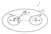
- FIG. 1 is a diagram illustrating a configuration of a wireless communication system according to the first embodiment.
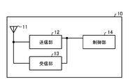
- FIG. 2 is a functional block diagram showing the configuration of the radio station according to the first embodiment.
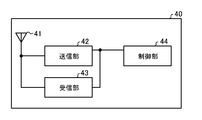
- FIG. 3 is a functional block diagram showing the configuration of the wireless terminal according to the first embodiment.
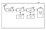
- FIG. 4 is a diagram illustrating a hardware configuration of the radio station according to the first embodiment.
- FIG. 5 is a diagram illustrating a hardware configuration of the wireless terminal according to the first embodiment.
- FIG. 6 is a sequence diagram for explaining the operation of the wireless communication system according to the first embodiment.
- FIG. 7 is a functional block diagram showing a configuration of a radio station of the radio communication system according to the second embodiment.
- FIG. 1 is a diagram illustrating a configuration of a wireless communication system according to the first embodiment.
- FIG. 2 is a functional block diagram showing the configuration of the radio station according to the first embodiment.
- FIG. 3 is a functional block diagram showing the configuration of the wireless terminal according to the first embodiment.
- FIG. 8 is a functional block diagram showing a configuration of a wireless terminal of the wireless communication system according to the second embodiment.
- FIG. 9 is an explanatory diagram regarding the operation of the wireless communication system according to the second embodiment.
- FIG. 10 is an explanatory diagram regarding the operation of the wireless communication system according to the second embodiment.
- FIG. 11 is a sequence diagram for explaining the operation of the wireless communication system according to the second embodiment.
- FIG. 12 is an explanatory diagram regarding notification of the RP set according to the second embodiment.
- FIG. 13 is a table showing an example of control information for notifying an RP set according to the second embodiment.
- FIG. 14 is a table showing an example of control information for notifying the RP set according to the second embodiment.
- FIG. 15 is a table showing an example of control information for notifying the RP set according to the second embodiment.
- FIG. 16 is a sequence diagram for explaining the operation of the wireless communication system according to the third embodiment.
- FIG. 17 is an explanatory diagram regarding notification of an RP set according to the third embodiment.
- FIG. 18 is a diagram illustrating a configuration of a wireless communication system according to the fourth embodiment.
- FIG. 19 is a functional block diagram showing a configuration of a radio station according to the fourth embodiment.
- FIG. 20 is a functional block diagram showing a configuration of a wireless terminal according to the fourth embodiment.
- FIG. 1 shows a configuration of a wireless communication system 1 according to the first embodiment.
- the wireless communication system 1 includes wireless stations 10, 20, 30 and a wireless terminal 40.
- Each of the radio stations 10, 20, and 30 has an antenna and is disposed at a point distant from each other.
- Each of the radio stations 10, 20, and 30 corresponds to a communication point.
- the radio station 10 forms a cell C10, and the radio stations 20 and 30 form cells C20 and 30 that overlap the cell C10, respectively.
- the radio terminal 40 exists in the cell C10 and the cell C20.
- the wireless stations 10, 20, and 30 perform communication between the wireless stations 10, 20, and 30 via a wired connection or a wireless connection.
- the radio stations 10, 20, and 30 can perform CoMP communication with the radio terminal 40.
- the wireless terminal 40 receives the same time from one or more communication points selected as a set to be used for downlink CoMP communication among the wireless stations 10, 20, and 30.
- -Combined transmission in which data is transmitted using radio resources of frequencies is performed.
- a combining process for receiving data and combining received signals between communication points is performed.
- the cells C20 and C30 formed by the radio stations 20 and 30 are included in the cell C10 formed by the radio station 10, but the present invention is not limited to this. Any CoMP communication may be used.
- each of the radio stations 10 to 30 is connected to a host device via a wired connection, and the host device is connected to a network via a wire connection.
- the radio stations 10 to 30 are provided so as to be able to transmit and receive data and control information via a host device or a network.
- FIG. 2 is a functional block diagram showing the configuration of the radio station 10.
- the radio station 10 includes an antenna 11, a transmission unit 12, a reception unit 13, and a control unit 14. Each of these components is connected so that signals and data can be input and output in one direction or in both directions.
- the functional configuration and hardware configuration of the radio stations 20 and 30 are the same as the functional configuration and hardware configuration of the radio station 10.
- the transmission unit 12 transmits a data signal and a control signal via the antenna 11.
- Signals to be transmitted include, for example, signals for reporting system information, L1 / L2 (Layer 1 / Layer 2) control signals such as L1 (Layer 1) signaling and MAC (Medium Access Control) signaling, RRC (Radio Resource Control) Includes upper layer control signals such as signaling.
- the receiving unit 13 receives the data signal and the control signal transmitted from the wireless terminal 40 via the antenna 11.
- the received signal includes, for example, a signal for establishing a connection and a signal indicating reception quality at the wireless terminal 40.
- the antenna 11 may be separated for transmission and reception.
- the control unit 14 acquires information and signals from the host device and other wireless stations via wired connection or wireless connection.
- the control unit 14 outputs data to be transmitted and control information to the transmission unit 12.
- the control unit 14 inputs received data and control information from the reception unit 13.
- the control unit 14 causes the transmission unit 12 to transmit control information. Further, the control unit 14 causes the transmission unit 12 to transmit a reference signal for obtaining (measuring) reception quality and decoding the received signal.
- control information examples include system information, RRC information, and L1 / L2 control information.
- the system information is broadcast as broadcast information in the cell C10 via, for example, a broadcast channel or a shared channel specified by the broadcast channel.
- the system information is notified via an individual data channel specified by an individual control channel, for example.
- the RRC information is notified by RRC signaling through a dedicated data channel specified by the dedicated control channel.
- the L1 / L2 control information is notified by L1 signaling or MAC signaling through the dedicated control channel.
- System information is stored and transmitted in, for example, MIB (Master Information Block) or SIB (System Information Block).
- MIB Master Information Block
- SIB System Information Block
- system information include system master information, configuration information for establishing a connection, and the like.
- the RRC information includes control information related to acquisition of reception quality at the radio terminal 40.
- Control information related to acquisition of reception quality includes, for example, information related to a reference signal of a communication point from which the radio terminal 40 acquires reception quality.
- the RRC information includes first set information indicating a set of candidate communication points that are candidates for performing CoMP communication with a predetermined wireless terminal among a plurality of communication points capable of CoMP communication.
- the first set information includes information indicating a set of reception points (candidate reception point sets) that are candidates for receiving signals in uplink CoMP communication.
- the L1 / L2 control information includes, for example, second information indicating which communication point is actually used in the candidate communication point set previously notified to a predetermined wireless terminal.
- the second set information includes information indicating a set of reception points to be actually used (active reception point set) among the candidate reception point sets. Note that the L1 / L2 control signal is notified more frequently than the higher layer control signal.
- the control unit 14 determines a set of reception points that are candidates for receiving a signal from the wireless terminal 40 among communication points capable of CoMP communication, based on information regarding reception quality at the wireless terminal 40. In addition, the control unit 14 notifies in advance on the basis of the usage status of the radio resource when transmitting data from the radio terminal 40, and determines which reception point of the candidate reception point set is actually used. decide.
- FIG. 3 is a functional block diagram showing the configuration of the wireless terminal 40.
- the wireless terminal 40 includes an antenna 41, a transmission unit 42, a reception unit 43, and a control unit 44. Each of these components is connected so that signals and data can be input and output in one direction or in both directions.
- the transmitting unit 42 transmits a data signal and a control signal via the antenna 41.
- the signal to be transmitted includes, for example, a signal for establishing a connection, a signal for requesting scheduling for data transmission, and a signal for notifying information on reception quality.
- the receiving unit 43 receives the data signal and the control signal transmitted from the wireless terminal via the antenna 41.
- the antenna 41 may be separate for transmission and reception.
- the control unit 44 outputs data to be transmitted and control information to the transmission unit 42.
- the control unit 44 inputs data and control information received from the receiving unit 43.
- the control unit 44 acquires the reception signal of the reference signal for each communication point from the reference signal received from the radio stations 10, 20, 30 based on the control information regarding the acquisition of the reception quality notified from the radio station 10.
- the reception quality for each communication point is acquired.
- the control unit 44 notifies the wireless station 10 of the acquired reception quality for each communication point, and becomes a candidate for receiving a signal through uplink CoMP communication based on the first set information notified from the wireless station 10. Get a set of candidate receiving points.
- the control unit 44 determines which reception point of the notified candidate reception point set is actually used according to the second set information notified from the radio station 10 at the time of data transmission. And send data to the receiving point.
- FIG. 4 is a diagram illustrating a hardware configuration of the radio station 10.
- the radio station 10 includes, as hardware components, for example, an RF (Radio Frequency) circuit 10B including an antenna 10A, a DSP (Digital Signal Processor) 10C, and a CPU (Central Processing Unit) 10D. , Memories 10E and 10F, and a network IF (Interface) 10G.
- the CPU 10D is connected to be able to input and output various signals and data via a network IF 10G such as a switch.
- the memories 10E and 10F include at least one of RAM (Random Access Memory) such as SDRAM (Synchronous Dynamic Random Access Memory), ROM (Read Only Memory), and flash memory, and store programs, control information, and data.
- the transmitter 12 and the receiver 13 are realized by, for example, the RF circuit 10B.
- the control unit 14 is realized by an integrated circuit such as a DSP 10C or an integrated circuit such as a CPU 10D.
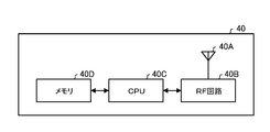
- FIG. 5 is a diagram illustrating a hardware configuration of the wireless terminal 40.
- the wireless terminal 40 includes, as hardware components, an RF circuit 40B including an antenna 40A, a CPU 40C, and a memory 40D, for example.
- LCD Liquid Crystal Display
- the memory 40D includes at least one of RAM such as SDRAM, ROM, and flash memory, for example, and stores programs, control information, and data.
- the transmission unit 42 and the reception unit 43 are realized by, for example, the RF circuit 40B.
- the control unit 44 is realized by an integrated circuit such as a CPU 40C, for example.
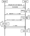
- FIG. 6 is a sequence diagram for explaining operations related to CoMP communication of the wireless communication system 1.
- the wireless stations 10, 20, and 30 are provided as communication points so as to be capable of CoMP communication.
- the wireless station 10 is a serving cell of the wireless terminal 40 and performs CoMP processing between the wireless stations 10, 20, and 30 in an aggregated manner.
- a communication point that is actually used for CoMP communication by the wireless terminal 40 is determined from the communication points at which CoMP communication is possible at the time of data communication.
- the communication points that are actually used are dynamically adjusted by the radio station 10 in a relatively short period.
- the wireless terminal 40 is notified of information indicating the communication point that is actually used.
- the wireless terminal 40 transmits data to the notified communication point that is actually used.
- the communication point can be designated by, for example, identification information assigned in advance.
- the identification information of each communication point is assumed to be about 8 [bit], for example.
- the number of communication points capable of CoMP communication is variable, and there may be many communication points capable of CoMP communication.
- the set of communication points to be actually used is variable for each dynamic adjustment, and the number and combination can be varied.
- a relatively large radio resource is secured.
- such identification information is sequentially notified to the radio terminal 40 in accordance with the adjustment timing, and transmission control is performed by the radio terminal 40 following this notification. Execute. At this time, notification of such identification information may increase signaling and hinder improvement in communication performance.
- the CoMP communication operation is performed as follows.
- control information related to acquisition of reception quality includes, for example, information related to a reference signal for each communication point for acquiring reception quality. This notification is executed by RRC signaling, for example.
- the wireless terminal 40 receives reference signals from a plurality of predetermined communication points among communication points capable of CoMP communication, and acquires reception quality for each communication point. And the radio
- the wireless station 10 receives a signal from the wireless terminal 4 through uplink CoMP communication among a plurality of transmission points capable of CoMP communication based on information on reception quality for each communication point at the wireless terminal 40.
- a candidate reception point set (candidate RP (Reception Point) set) that is a candidate to be selected is selected (S3). For example, a predetermined number of communication points having a high reception quality, or communication points having a reception quality of a predetermined level or higher are selected from the communication points. As a result, communication points smaller than the number of all communication points capable of CoMP communication are selected as candidate reception point sets.
- the wireless station 10 notifies the candidate terminal set to the wireless terminal 40 (S4).
- This notification is executed by RRC signaling, for example.
- the radio station 10 may also notify information on a set of transmission control parameters corresponding to the candidate reception point set.
- the radio station 10 selects an active reception point set (active RP set) that is actually used for signal reception when scheduling signal reception from the radio terminal 40 (S5).
- the radio station 10 notifies the radio terminal 40 of the active reception point set (S6).
- the active reception point set is notified by L1 signaling or MAC signaling through the dedicated control channel, for example.
- L1 signaling and MAC signaling are transmitted periodically or aperiodically at intervals of 1 [ms], for example. Since control is performed with a relatively short period in this way, CoMP communication can be performed by appropriately adjusting communication points by appropriately following changes in propagation environment and the like.
- the active reception point set is notified, for example, as information indicated in a bitmap format indicating by ⁇ 0, 1 ⁇ whether or not each reception point included in the candidate reception point set is used. As a result, the amount of signaling is reduced compared to the notification of the identification information of the reception point actually used.
- the radio terminal 40 sets transmission control according to the active reception point set (S7).
- the information to be set includes, for example, a transmission power calculation method, parameters used for transmission power calculation, and the like. As a result, transmission control is appropriately set according to the reception point actually used.
- the wireless terminal 40 transmits data according to the set transmission control (S8).
- the transmitted data is received at each receiving point.
- the radio station 10 acquires signals received at the respective reception points, and performs cooperative reception processing (for example, synthesis processing) (S9). Thereby, reduction of interference between communication points and improvement of received signal strength are achieved.
- cooperative reception processing for example, synthesis processing
- communication performance can be improved in a wireless communication system that performs CoMP communication.
- the wireless communication system 1 can be realized using the wireless stations 10, 20, and 30 as base stations.
- the radio stations 10, 20, and 30 can be realized as independent eNodeBs (evolved Node B).
- the radio communication system 1 may be realized by using the radio station 10 as a control unit of the base station and the radio stations 20 and 30 as remote units of the base station.
- the control unit can be realized as, for example, a centralized eNodeB
- the remote unit can be realized as, for example, an RRH (Remote Radio Radio Head) included in the centralized eNodeB.
- RRH Remote Radio Radio Head
- control unit is connected to the remote unit via a wired connection such as an optical cable.
- the control unit forms a cell, and each remote unit forms a cover area that overlaps the cell.
- control unit and the remote unit may use common cell identification information.
- the first set information corresponds to information indicating a set of candidate transmission points (candidate transmission point sets) that are candidates for transmitting signals in downlink CoMP communication and candidate transmission points.
- Communication control parameters may be included.
- the first set information may be information indicating a union of a set of candidate reception points and a set of candidate transmission points. Further, information on a set of communication control parameters corresponding to the candidate transmission point set may be notified together.
- the second set information may include information indicating a set of transmission points to be actually used (active transmission point set) out of the candidate transmission point set or the union of the candidate reception point set and the candidate transmission point set. Good.
- the wireless communication system according to the second embodiment includes three wireless stations 50 and a wireless terminal 70.
- the overall configuration of the radio communication system according to the second embodiment is the same as that of the radio communication system 1 shown in FIG.
- FIG. 7 is a functional block diagram showing the configuration of the radio station 50 of the radio communication system according to the second embodiment.
- the radio station 50 includes a receiving antenna 51, a radio processing unit 52, an FFT (Fast Fourier Transform) unit 53, a demodulation unit 54, a decoding unit 55, a MAC / RLC (Medium Access Control). (Radio Link Control) processing unit 56, radio resource control unit 57, MAC control unit 58, packet generation unit 59, MAC scheduling unit 60, encoding unit 61, modulation unit 62, and multiplexing unit 63 , An IFFT (Inverse Fast Fourier Transform) unit 64, a radio processing unit 65, and a transmission antenna 66.
- FFT Fast Fourier Transform
- the receiving antenna 51 receives a radio signal and outputs it to the radio processing unit 52.
- the radio station 50 may include a plurality of reception antennas. Further, the reception antenna 51 may be configured such that, together with the transmission antenna 66, the transmission / reception antenna is switched between transmission and reception by a transmission / reception switching unit or the like.
- the reception antenna 51 receives an uplink signal via, for example, an uplink data channel or a control channel. Channels for receiving signals include PRACH (Physical Random Access Channel), PUSCH (Physical Uplink Shared Channel), and PUCCH (Physical Uplink Control Channel).
- the uplink signal includes a reference signal RS (Reference Signal), a control signal, and a data signal.
- the uplink signal includes, for example, a signal for notifying information indicating reception quality for each communication point at the wireless terminal 40.
- the wireless processing unit 52 performs processing such as A / D (Analog-to-Digital) conversion on the received signal.
- the FFT unit 53 performs FFT processing on the digital signal.
- the demodulator 54 demodulates the FFT-processed signal based on control information notified or stored in advance or a reference signal for demodulation.
- the decoding unit 55 performs a decoding process on the demodulated signal based on channel information estimated from control information or a reference signal notified or stored in advance. The decoding process is performed using, for example, a PUSCH channel estimation value estimated using a reference signal.
- the MAC / RLC processing unit 56 performs reordering processing of the decoded signal, and acquires and outputs the received data.
- the received data is stored in, for example, a reception buffer and processed by the application processing unit.
- the MAC / RLC processing unit 56 outputs reception quality acquired from the received signal, control information, and the like.
- the MAC / RLC processing unit 56 outputs ACK (ACKnowledgement) / NACK (Negative ACKnowledgement) to the radio resource control unit 57 as a decoding result of the data signal.
- the radio resource control unit 57 determines control information related to acquisition of reception quality at the radio terminal 70 based on information about communication points capable of CoMP communication acquired from the host device, and outputs the control information to the packet generation unit 59.
- Control information related to acquisition of reception quality includes, for example, information related to a communication point for measuring reception quality.
- Information relating to a communication point for measuring reception quality includes, for example, RSRP measurement set indicating a set of communication points for measuring RSRP (Reference Signal Received Power).
- the radio resource control unit 57 determines a candidate RP set (Candidate RP set) based on the reception quality of each communication point acquired by the radio terminal 40.
- the candidate RP set is determined based on RSRP report that notifies the RSRP measured for each communication point as information indicating the reception quality for each communication point at the wireless terminal 70.
- the radio resource control unit 57 schedules signal reception from the radio terminal 70 and notifies the MAC control unit 58 of the scheduling result.
- the MAC control unit 58 outputs data indicating an active RP set determined by scheduling of signal reception from the wireless terminal 70 to the packet generation unit 59. Further, the MAC control unit 58 notifies the MAC scheduling unit 60 of control information for MAC scheduling. Further, the MAC control unit 58 outputs a control signal to be transmitted to the multiplexing unit 63 via a PDCCH (Physical Downlink Control Channel).
- PDCCH Physical Downlink Control Channel
- the packet generator 59 generates a packet from user data, candidate RP set information, active RP set information, and RSRP measurement measurement information. For example, user data is acquired from a higher-level device or another wireless station and stored in a transmission buffer.
- the MAC scheduling unit 60 performs processing such as assigning the generated packet to a transport block.
- the encoding unit 61 encodes transmission data based on the control information.
- the modulation unit 62 modulates the encoded data based on the control information.
- the multiplexing unit 63 allocates modulated transmission data, a reference signal (pilot signal), an individual control signal (PDCCH), and the like to radio resources.
- the IFFT unit 64 performs IFFT processing on the multiplexed signal.
- the radio processing unit 65 performs A / D conversion, distortion compensation processing, amplification processing, and the like on the signal after IFFT processing, and outputs the result to the transmission antenna 66.
- the transmission antenna 66 transmits a wireless signal input from the wireless processing unit 65.
- the radio station 50 may include a plurality of transmission antennas.
- the transmission antenna 66 transmits a downlink signal through, for example, a downlink data channel or a control channel.
- Channels for transmitting signals include, for example, a synchronization channel PSCH (Physical Synchronization Channel), a broadcast channel PBCH (Physical Broadcast Channel), a PDSCH (Physical Downlink Shared Channel), and a PDCCH.
- the downlink signal includes a reference signal, a control signal, and a data signal.
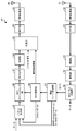
- FIG. 8 is a functional block diagram showing the configuration of the wireless terminal 70 of the second embodiment.
- the wireless terminal 70 includes a data processing unit 71, a multiplexing unit 72, a symbol mapping unit 73, a multiplexing unit 74, an FFT unit 75, a frequency mapping unit 76, an IFFT unit 77, a wireless processing unit 78, a transmission / reception unit, A reception antenna 79, a radio processing unit 80, an FFT unit 81, a demodulation unit 82, a decoding unit 83, a control information processing unit 84, a control channel demodulation unit 85, and a transmission control unit 86 are included.
- the transmission / reception antenna 79 can be switched between transmission and reception, and in the case of transmission, a signal output from the wireless processing unit 78 is transmitted via the transmission / reception antenna 79. In the case of reception, a signal received via the transmission / reception antenna 79 is input to the wireless processing unit 80.
- the antenna may be separated for transmission and reception. Further, a plurality of antennas may be provided.
- the radio processing unit 80 inputs the received downlink radio signal and performs A / D conversion and the like.
- the FFT unit 81 performs FFT processing on the radio-processed signal, and acquires a subcarrier signal from the received OFDM (Orthogonal Frequency Division Multiplexing) signal.
- the demodulator 82 demodulates the data signal using the control information notified through the dedicated control channel.
- the decoding unit 83 decodes the demodulated data signal using the control information notified through the dedicated control channel.
- the received data obtained by decoding is stored in, for example, a reception buffer and processed by the application processing unit.
- the control information obtained by decoding is output to the control information processing unit 84. Examples of the control information include RRC information, MAC-CE (Medium Access Control-Control Control Element) control information, broadcast information, and paging information. Also, the reception quality is acquired from the acquired reference signal.
- the control information processing unit 84 processes the received control information and outputs it to the control channel demodulation unit 85 and the transmission control unit 86.
- the control information processing unit 84 outputs RNTI (Radio Network Temporary Identity) information to the control channel demodulation unit 85.
- the control information processing unit 84 outputs active RP set information used by the transmission control unit 86 and transmission power control parameters.
- the control information processing unit 84 outputs information on the active RP set to the transmission control unit 86 from the candidate RP set information notified by RRC signaling and the bitmap information indicating the active RP set notified by MAC signaling.
- the control channel demodulation unit 85 demodulates the control channel information based on the RNTI information, and outputs control information used by the demodulation unit 82 and the decoding unit 83.
- the data processing unit 71 generates a data signal from the transmission data.
- the transmission data is processed by the application processing unit and stored in the transmission buffer.
- the multiplexing unit 72 multiplexes the control signal generated from the RRC / MAC-CE control information on the data signal.
- the symbol mapping unit 73 maps the transmission signal in the time axis direction.
- the multiplexing unit 74 multiplexes a reference signal (pilot signal) on the symbol-mapped signal.
- the FFT unit 75 performs FFT processing on the multiplexed signal.
- the frequency mapping unit 76 maps the FFT-processed signal in the frequency direction.
- the IFFT processing unit 77 performs IFFT processing on the frequency mapped signal to generate a transmission signal.
- the wireless processing unit 78 performs D / A (Digital-to-Analog) conversion processing on the IFFT-processed signal and outputs the signal to the transmission / reception antenna 79.
- D / A Digital-to-Analog
- the transmission control unit 86 determines transmission power based on the control information.
- the transmission power of the uplink shared channel (PUSCH) in cell c and subframe i is expressed by the following equation (1).
- P MAX, c (i) is the maximum transmission power
- M PUSCH, c (i) is the size of the allocated frequency resource (RB; Resource Block), and P 0_PUSCH, c (j) is for dynamic scheduling, for example.
- PL c is a path loss (propagation loss) estimated using a downlink signal
- a is a path loss coefficient (indicating the degree of compensation for the path loss).
- D TF, c (i) is an offset value for each modulation and coding scheme (MCS)
- f c (i) is an offset value by closed loop control using a TPC command.
- the parameters P 0_PUSCH, c (j), a related to the open loop TPC for compensating for the path loss are stored in advance in the wireless terminal 70 or notified from the wireless station 50 and selected according to the active RP set.
- PL serving is the RP path loss of the connected cell
- PL 1 , PL 2 ,..., PL N are the path loss of each RP of the serving cell and the cooperative cell.
- the conversion method (a) compensates for the path loss of the serving cell.
- the conversion method (b) compensates for the maximum path loss in the serving cell and the cooperative cell.
- the conversion method (c) compensates for the minimum path loss in the serving cell and the cooperative cell.
- the conversion method (d) compensates for the nonlinear average path loss (path loss converted from the gain of JR).
- the hardware configuration of the radio station 50 in the radio communication system according to the second embodiment is the same as the hardware configuration of the radio station 10 of FIG.
- the reception antenna 51, the wireless processing unit 52, the wireless processing unit 65, and the transmission antenna 66 of the wireless station 50 are realized by an antenna and an RF circuit, for example.
- the unit 60, the encoding unit 61, the modulation unit 62, the multiplexing unit 63, and the IFFT unit 64 are realized by an integrated circuit such as a DSP or an integrated circuit such as a CPU.
- the hardware configuration of the wireless terminal 70 in the wireless communication system according to the second embodiment is the same as the hardware configuration of the mobile terminal 40 in FIG.
- the wireless processing unit 78, the transmission / reception antenna 79, and the wireless processing unit 80 of the wireless terminal 70 are realized by, for example, an antenna and an RF circuit.
- the unit 84, the control channel demodulation unit 85, and the transmission control unit 86 are realized by an integrated circuit such as a CPU.
- the three wireless stations 50 are provided as communication points so as to be capable of CoMP communication.
- One radio station 50 is a serving cell of the radio terminal 70, and performs CoMP processing between the three radio stations 50 in an aggregated manner. Then, at the time of data communication, a communication point that is actually used for CoMP communication by the wireless terminal 70 is determined at the time of data communication from communication points at which CoMP communication is possible.
- FIG. 9 shows a sequence diagram of generally assumed CoMP communication operation as a related technique.
- the radio station notifies control information RSRP measurement set information related to acquisition of reception quality at the radio terminal (S31).
- the wireless terminal receives the notified control information.
- pilot signals from a plurality of predetermined communication points among communication points capable of CoMP communication are received, and reception quality for each communication point is acquired.
- the wireless terminal transmits reception quality information RSRP report to the wireless station (S32).
- the radio station performs uplink CoMP communication among a plurality of communication points capable of CoMP communication based on information on reception quality for each communication point at the radio terminal when scheduling signal reception from the radio terminal 40.
- the active RP set to be used for signal reception from the wireless terminal is selected (S33).
- the communication point used for signal reception is dynamically adjusted by the radio station 50 in a relatively short period.
- the radio station 50 notifies the radio terminal 70 of the active RP set (S34).
- each reception point is designated by identification information assigned in advance, for example.
- the radio terminal 70 switches transmission control according to the active RP set (S35), and transmits data (S36).
- the radio station 50 acquires signals received at the respective reception points, and performs cooperative reception processing (for example, synthesis processing) (S37).
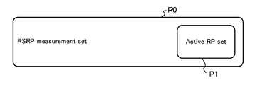
- FIG. 10 schematically shows the selection of the active RP set in the above case.
- the set P0 of RSRP measurement set notified in S31 as a mother set in S32, the number of active RP sets and combinations of the set P1 of active RP sets can be variously changed.
- a radio resource capable of transmitting the identification information of the entire RSRP measurement set is secured. Then, such identification information is notified at a relatively short period in S34. In this case, an increase in signaling may occur, which may hinder improvement in communication performance.
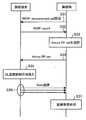
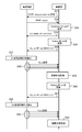
- FIG. 11 is a sequence diagram for explaining operations related to CoMP communication of the wireless communication system
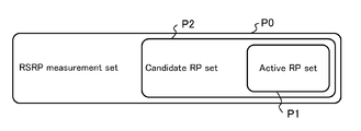
- FIG. 12 is a diagram schematically illustrating selection of an active RP set.
- the radio station 50 notifies the radio terminal 70 of control information RSRP measurement set relating to acquisition of reception quality (S51).
- FIG. 12 shows a set P0 of RSRP measurement set.
- the wireless terminal 70 receives pilot signals from a plurality of predetermined communication points among communication points capable of CoMP communication, and acquires reception quality for each communication point. Then, the wireless terminal 70 transmits reception quality information RSRP report to the wireless station 50 (S52).
- the radio station 50 receives a signal from the radio terminal 70 by uplink CoMP communication among a plurality of transmission points capable of CoMP communication based on information on reception quality for each communication point at the radio terminal 70.
- a candidate reception point set to be a candidate to be selected is selected (S53). For example, a predetermined number of communication points having a high reception quality, or communication points having a reception quality of a predetermined level or higher are selected from the communication points.
- FIG. 12 illustrates a set P2 of candidate RP sets. As shown in FIG. 12, communication points smaller than the number of communication points in RSRP measurement set (set P0) are selected as candidate RP sets (set P2). As a result, communication points smaller than the number of all communication points capable of CoMP communication are selected as candidate RP sets.
- the radio station 50 notifies the candidate RP set to the radio terminal 70 (S54). This notification is executed by RRC signaling, for example. At this time, since communication points smaller than the number of all communication points capable of CoMP communication are selected as candidate RP sets, the amount of signaling is reduced rather than notifying the identification information of all communication points. At this time, the radio station 50 may also notify information for transmission control setting corresponding to the candidate RP set.
- FIG. 12 illustrates a set P1 of active RP sets.
- the active RP set (set P1) is selected from the candidate RP sets (set P2).
- the candidate RP sets (set P2) For example, as shown in FIG. 12, communication points fewer than the number of communication points of RSRP measurement set (set P0) are selected as candidate RP sets (set P2), so select from RSRP measurement set (set P0) Compared to the case, the number and combination of reception points can be reduced.
- the radio station 50 notifies the radio terminal 70 of the active RP set (S56).
- the active RP set is notified by L1 signaling or MAC signaling through the dedicated control channel, for example.
- the active RP set is notified by information indicating which of the candidate RP sets is used, for example.
- the active RP set is notified as, for example, information indicated in a bitmap format indicating by ⁇ 0, 1 ⁇ whether or not each communication point included in the candidate RP set is used.
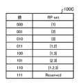
- FIGS. 13 to 15 show tables 100A to 100C showing examples of active RP sets.
- an active RP set selected from a candidate reception point set including three candidate reception points is 3 [bit] information indicated by ⁇ 0, 1 ⁇ .
- the amount of signaling is reduced compared to the notification of the identification information of the reception point actually used.
- the wireless terminal 70 switches transmission control according to the active RP set (S57).
- the information to be set includes, for example, a transmission power calculation method, parameters used for transmission power calculation, and the like. As a result, transmission control is appropriately set according to the reception point actually used.
- the wireless terminal 70 transmits data according to the set transmission control (S58).
- the transmitted data is received at each receiving point.
- the radio station 50 acquires signals received at the respective reception points, and performs cooperative reception processing (for example, synthesis processing) (S59). Thereby, reduction of interference between communication points and improvement of received signal strength are achieved.
- cooperative reception processing for example, synthesis processing
- the radio station 50 updates the RP set that is actually used for signal reception when scheduling the signal reception from the radio terminal 40 (S60).
- the radio station 50 notifies the radio terminal 70 of the active RP set (S61). At this time, notification may be made only when there is a change in the active RP set.
- the radio terminal 70 switches transmission control according to the active RP set (S62). As a result, transmission control is appropriately set according to the reception point actually used.
- the wireless terminal 70 transmits data according to the set transmission control (S63). The transmitted data is received at each receiving point.
- the radio station 50 acquires signals received at the respective reception points, and performs cooperative reception processing (for example, synthesis processing) (S64). Thereby, reduction of interference between communication points and improvement of received signal strength are achieved.
- communication performance can be improved in a wireless communication system that performs CoMP communication.
- the wireless communication system can realize three wireless stations 50 as base stations.
- the three radio stations 50 can be realized as independent eNodeBs.
- the radio communication system may be realized by using one radio station 50 as a control unit of a base station and another radio station as a remote unit of the base station.
- the control unit can be realized as, for example, a centralized eNodeB
- the remote unit can be realized as, for example, an RRH included in the centralized eNodeB.
- the control unit is connected to the remote unit via a wired connection such as an optical cable.
- the control unit forms a cell, and each remote unit forms a cover area that overlaps the cell.
- the control unit and the remote unit may use common cell identification information.
- FIG. 16 is a sequence diagram for explaining an operation related to CoMP communication of the radio communication system according to the third embodiment
- FIG. 17 is a diagram schematically illustrating selection of an active RP set.
- the overall configuration of the wireless communication system according to the third embodiment is the same as the configuration of the wireless communication system 90 of FIG.
- the radio station according to the third embodiment is different from the radio station 50 according to the second embodiment in operations related to the radio resource control unit 57 and the MAC control unit 58.
- the radio resource control unit 57 determines a candidate RP set based on the reception quality of each communication point measured by the radio terminal 40, and a candidate for transmitting a signal by downlink CoMP communication.
- a candidate transmission point set (candidate TP (Transmission Point) set) is determined. Then, information indicating the union of the candidate RP set and the candidate TP set (Candidate TP set) is output to the packet generation unit 59.
- the MAC control unit 58 outputs data indicating an active RP set determined by signal reception scheduling to the packet generation unit 59 and also sets an active transmission point set (determined by signal transmission scheduling). Data indicating the active TP set (Active TP set) is output to the packet generator 59.
- Other configurations of the radio station according to the third embodiment are the same as the configurations of the radio station 50 of FIG. 7 of the second embodiment.
- the hardware configuration of the radio station according to the third embodiment is the same as the hardware configuration of the radio station 50 according to the second embodiment.
- the wireless terminal according to the third embodiment is different from the wireless station 70 of the second embodiment in the operation related to the control information processing unit 84.
- the control information processing unit 84 processes the received control information and outputs it to the control channel demodulation unit 85, the transmission control unit 86, and the multiplexing unit 72. For example, the control information processing unit 84 outputs active TP set information.
- the control information processing unit 84 outputs information on the active TP set from the candidate RP / TP set information notified by RRC signaling and the bitmap information indicating the active TP set notified by MAC signaling.
- the radio station 50 (described as eNB in FIG. 16) notifies control information RSRP measurement set related to acquisition of reception quality at the radio terminal 70 (described as UE in FIG. 16).
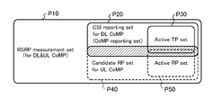
- FIG. 17 illustrates a set P10 of RSRP ⁇ measurement set.
- the wireless terminal 70 receives reference signals from a plurality of predetermined communication points among communication points capable of CoMP communication, and acquires reception quality for each communication point. Then, the wireless terminal 70 transmits reception quality information RSRP report to the wireless station 50 (S72).
- the wireless station 50 receives a signal from the wireless terminal 70 through uplink CoMP communication among a plurality of communication points capable of CoMP communication based on information on reception quality at each communication point at the wireless terminal 70.
- FIG. 17 illustrates a set P20 of candidate RP sets and a set P40 of candidate TP sets. In FIG.
- the hatched area is an overlapping portion between the candidate PRP set P20 and the candidate TP set P40.
- communication points fewer than the number of communication points in RSRP measurement set (set P10) are selected as candidate RP sets (set P20) and candidate TP sets (set 40).
- communication points smaller than the number of all communication points capable of CoMP communication are selected as candidate RP sets and candidate TP sets.
- the radio station 50 notifies the radio terminal 70 of information indicating the union of the candidate RP set and the candidate TP set (S74).
- This notification is executed by RRC signaling, for example.
- the radio station 50 since communication points smaller than the number of all communication points capable of CoMP communication are selected as candidate RP sets and candidate TP sets, the amount of signaling is reduced rather than notifying the identification information of all communication points. And since the identification information of the communication point to notify about the part which a candidate RP point and a candidate TP point overlap can be reduced, a signaling amount can be reduced and communication performance can be aimed at.
- the radio station 50 may also notify information for transmission control setting corresponding to the candidate RP set.
- FIG. 17 illustrates a set P30 of active RP sets and a set P50 of active TP sets.
- an active RP set (set P30) is selected from candidate RP sets (set P20)
- an active RP set (set P50) is selected from candidate TP sets (set P40). .
- FIG. 17 illustrates a set P30 of active RP sets and a set P50 of active TP sets.
- an active RP set (set P30) is selected from candidate RP sets (set P20)
- an active RP set (set P50) is selected from candidate TP sets (set P40). .
- the radio station 50 notifies the radio terminal 70 of the active RP set and the active TP set (S76).
- the active RP set and the active TP set are notified by L1 signaling or MAC signaling via the dedicated control channel.
- the active RP set is notified by information indicating which of the candidate RP sets is used, for example.
- the active TP set is notified by information indicating which of the candidate TP sets is used, for example.
- communication points fewer than the number of communication points of RSRP measurement set (set P10) are selected as candidate RP sets (set P20) and candidate TP sets (set P40).
- the number and combinations of reception points and transmission points that can be taken are reduced, and the amount of signaling is reduced compared to the case of notifying the information specified from RSRP measurement set (set P10). Since fewer communication points than the number of all communicable communication points are selected as candidate RP sets, the number and combinations that can be taken compared to the case of notifying the information to be specified from all CoMP communicable sets And the amount of signaling is reduced.
- the active RP set and the active TP set are, for example, information indicating in bitmap format indicating by ⁇ 0, 1 ⁇ whether or not each communication point included in the candidate RP set and candidate TP set is used. Be notified. As a result, the amount of signaling is reduced by notifying the identification information of the reception point and transmission point that are actually used.
- the wireless terminal 70 switches transmission control according to the active RP set (S77).
- the information to be set includes, for example, a transmission power calculation method, parameters used for transmission power calculation, and the like. As a result, transmission control is appropriately set according to the reception point actually used.
- the wireless terminal 70 transmits data according to the set transmission control (S78).
- the transmitted data is received at each receiving point. Further, the wireless terminal 70 receives data transmitted from each transmission point.
- the radio station 50 acquires signals received at the respective reception points, and performs cooperative transmission / reception processing (for example, synthesis processing) (S79). Further, the wireless terminal 70 performs a process of combining signals transmitted from the transmission points. Thereby, reduction of interference between communication points and improvement of received signal strength are achieved.
- cooperative transmission / reception processing for example, synthesis processing
- the radio station 50 updates the active RP set and active TP set that are actually used for signal reception when scheduling signal reception from the radio terminal 40 (S80).
- the radio station 50 notifies the radio terminal 70 of the active RP set and the active TP set as in S76 (S81).
- the active RP set may be notified only when the active RP set is changed.
- the active TP set may be notified only when there is a change in the active TP set.
- the wireless terminal 70 switches transmission control according to the active RP set (S82). As a result, transmission control is appropriately set according to the reception point actually used.
- the wireless terminal 70 transmits data according to the set transmission control (S83).
- the transmitted data is received at each receiving point. Further, the wireless terminal 70 receives data transmitted from each transmission point. Next, similarly to S79, the radio station 50 acquires signals received at the respective reception points, and performs cooperative transmission / reception processing (for example, synthesis processing) (S84). Thereby, reduction of interference between communication points and improvement of received signal strength are achieved.
- cooperative transmission / reception processing for example, synthesis processing
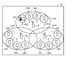
- FIG. 18 is a diagram illustrating a configuration of a wireless communication system 110 according to the fourth embodiment.
- the radio station 160 includes a control unit 120 and remote units 150A to 150D, as shown in the next figure (FIG. 19).
- another radio station (not shown) has a control unit 130 and remote units 150E-150H.
- yet another radio station (not shown) has a control unit 140 and remote units 150I-150J.
- the control units 120, 130, and 140 can be realized as eNodeB, for example.
- the remote units 150A to 150L can be realized as, for example, the RRH included in the eNodeB.
- the control units 120, 130, 140 and remote units 150A to 150L each have an antenna and are arranged at points distant from each other.
- control units 120, 130, and 140 and the remote units 150A to 150L each correspond to a communication point.
- Control units 120, 130, and 140 form cells C120, C130, and C140, and remote units 150A to 150L form cover areas A to L, respectively.
- the radio terminal 200 exists in the cell C120. At this time, the wireless terminal 200 is included in the cover area A.
- the control unit 120 and the remote units 150A to 150D communicate with each other via a wired connection.
- the control unit 130 and the remote units 150E to 150H communicate with each other via a wired connection.
- the control unit 140 and the remote units 150I to 150J communicate with each other via a wired connection.
- a radio station 160, another radio station (not shown), a control unit 120, 130, 140 of another radio station (not shown), and remote units 150A to 150L are mixed, At least some of these perform CoMP communication.
- wireless communication is performed from one or more communication points selected as a set to be used for downlink CoMP communication among the control units 120, 130, and 140 and the remote units 150A to 150L.
- the data is combined and transmitted to the terminal 200.
- uplink CoMP communication with the radio terminal 200 at one or more communication points selected as a set to be used for uplink CoMP communication among the control units 120, 130, 140 and the remote units 150A to 150L.
- the data from the wireless terminal 200 is received, and the received signal is synthesized between the communication points.
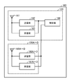
- FIG. 19 is a functional block diagram showing the configuration of the radio station 160.
- the control unit 120 of the radio station 160 includes an antenna 161, a transmission unit 162, a reception unit 163, and a control unit 164.
- Remote units 150A to 150D of radio station 160 each include antennas 165A to 165D, transmitters 166A to D, and receivers 167A to 167D. Each of these components is connected so that signals and data can be input and output in one direction or in both directions.
- the antennas 165A to 165D and the antenna 161 have the same configuration.
- the transmission units 166A to 166D and the transmission unit 162 have the same configuration.
- the receiving units 167A to 167D and the receiving unit 163 have the same configuration.
- the functional configuration and hardware configuration of another radio station (not shown) and yet another radio station (not shown) are the same as those of the radio station 160.
- the transmission unit 162 and the reception unit 163 have the same configuration as the transmission unit and the reception unit of the first
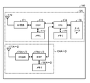
- FIG. 20 is a diagram showing a hardware configuration of the radio station 160.
- the radio station 160 includes, as hardware components, for example, RF circuits 171, 178A to D including antennas 170 and 177A to D, DSPs 172 and 179A to D, and memories 173 and 180A to D.
- the CPU 174 is connected through a network IF 176 such as a switch so that various signals and data can be input and output.
- the memories 173, 180A to D, 175 include at least one of RAM such as SDRAM, ROM, and flash memory, for example, and store programs, control information, and data.
- the transmitters 162 and 166A to D and the receivers 163 and 167A to D are realized by integrated circuits such as RF circuits 171, 178A to D and 172, 179A to D, for example.
- the control unit 164 is realized by an integrated circuit such as the CPU 174, for example.
- the control unit 120 corresponds to the components 170 to 176, and the remote units 150A to 150D correspond to the components 177A to D, 178A to D, 179A to D, and 180A to D.
- the functional configuration and hardware configuration of the wireless terminal 200 according to the fourth embodiment are the same as those of the wireless terminal 40 of the first embodiment.
- a set of candidate reception points is selected and notified to the wireless terminal 200 as in the description of FIG. 6 of the first embodiment.
- the amount of signaling is reduced rather than notifying the identification information of all communication points.
- an active reception point is selected and notified to the radio terminal 200.
- the active RP set is notified by information indicating which of the candidate RP sets is used, for example.
- the active RP set is notified as, for example, information indicated by a bitmap format indicating by ⁇ 0, 1 ⁇ whether each communication point included in the candidate RP set is used. As a result, the amount of signaling is reduced compared to the notification of the identification information of the reception point actually used.
- communication performance can be improved in a wireless communication system that performs CoMP communication.
- control unit 164 of the control unit 120 outputs data signals and control signals to be transmitted to the transmission unit 162 and the transmission units 166A to 166A-D.
- the control unit 164 inputs received data and control information from the reception unit 163 and the reception units 167A to 167D.
- Other parts are the same as in the first embodiment.
- the wireless communication systems of the first to fourth embodiments can be realized as, for example, an LTE-A system.
- the present invention can also be applied to a wireless communication system using a communication method other than LTE-A.
- the first to fourth embodiments can be applied to mobile terminals such as mobile phones, smartphones, and PDAs (Personal Digital Assistants) as wireless terminals.
- the first to fourth embodiments can be applied to various communication devices that communicate with a base station such as a mobile relay station.
- first to fourth embodiments can be applied to base stations of various scales such as macro base stations and femto base stations as radio stations.
- first to fourth embodiments can be applied to various communication devices that communicate with mobile stations such as relay stations.
- each component of the radio station and radio terminal is not limited to the mode of the first to fourth embodiments, and all or a part thereof can be used for various loads, usage conditions, etc. Accordingly, it may be configured to be functionally or physically distributed / integrated in an arbitrary unit.
- the memory may be connected via a network or a cable as an external device of a wireless station or a wireless terminal.
- Radio communication system 10 20, 30, 50 Radio station 40, 70 Radio terminal C10, C20, C30 Cell 11, 41 Antenna 12, 42 Transmitter 13, 43 Receiver 14, 44 Controller 10A, 40A Antenna 10B, 40B RF circuit 10C DSP 10D, 40C CPU 10E, 10F, 40D Memory 10G Network IF 51 reception antenna 52 radio processing unit 53 FFT unit 54 demodulation unit 55 decoding unit 56 MAC / RLC processing unit 57 radio resource control unit 58 MAC control unit 59 packet generation unit 60 MAC scheduling unit 61 encoding unit 62 modulation unit 63 multiplexing unit 64 IFFT unit 65 Radio processing unit 66 Transmitting antenna 71 Data processing unit 72 Multiplexing unit 73 Symbol mapping unit 74 Multiplexing unit 75 FFT unit 76 Frequency mapping unit 77 IFFT unit 78 Radio processing unit 79 Antenna 80 Radio processing unit 81 FFT unit 82 Demodulating unit 83 Decoding unit 84 Control information processing unit 85 Control channel demodulation unit 86 Transmission control unit 110
Landscapes
- Engineering & Computer Science (AREA)
- Computer Networks & Wireless Communication (AREA)
- Signal Processing (AREA)
- Quality & Reliability (AREA)
- Mobile Radio Communication Systems (AREA)
Abstract
Priority Applications (6)
| Application Number | Priority Date | Filing Date | Title |
|---|---|---|---|
| JP2014505789A JP5896016B2 (ja) | 2012-03-19 | 2012-03-19 | 無線通信方法、無線通信システム、無線局、及び無線端末 |
| CN201280071516.4A CN104170448B (zh) | 2012-03-19 | 2012-03-19 | 无线通信方法、无线通信系统、无线站以及无线终端 |
| PCT/JP2012/001904 WO2013140434A1 (fr) | 2012-03-19 | 2012-03-19 | Procédé de communication radio, système de communication radio, station radio et terminal radio |
| KR1020147025728A KR101644494B1 (ko) | 2012-03-19 | 2012-03-19 | 무선 통신 방법, 무선 통신 시스템, 무선국 및 무선 단말기 |
| EP12871829.3A EP2830354A4 (fr) | 2012-03-19 | 2012-03-19 | Procédé de communication radio, système de communication radio, station radio et terminal radio |
| US14/487,670 US9730195B2 (en) | 2012-03-19 | 2014-09-16 | Radio communication method, radio communication system, radio station, and radio terminal |
Applications Claiming Priority (1)
| Application Number | Priority Date | Filing Date | Title |
|---|---|---|---|
| PCT/JP2012/001904 WO2013140434A1 (fr) | 2012-03-19 | 2012-03-19 | Procédé de communication radio, système de communication radio, station radio et terminal radio |
Related Child Applications (1)
| Application Number | Title | Priority Date | Filing Date |
|---|---|---|---|
| US14/487,670 Continuation US9730195B2 (en) | 2012-03-19 | 2014-09-16 | Radio communication method, radio communication system, radio station, and radio terminal |
Publications (1)
| Publication Number | Publication Date |
|---|---|
| WO2013140434A1 true WO2013140434A1 (fr) | 2013-09-26 |
Family
ID=49221941
Family Applications (1)
| Application Number | Title | Priority Date | Filing Date |
|---|---|---|---|
| PCT/JP2012/001904 Ceased WO2013140434A1 (fr) | 2012-03-19 | 2012-03-19 | Procédé de communication radio, système de communication radio, station radio et terminal radio |
Country Status (6)
| Country | Link |
|---|---|
| US (1) | US9730195B2 (fr) |
| EP (1) | EP2830354A4 (fr) |
| JP (1) | JP5896016B2 (fr) |
| KR (1) | KR101644494B1 (fr) |
| CN (1) | CN104170448B (fr) |
| WO (1) | WO2013140434A1 (fr) |
Cited By (4)
| Publication number | Priority date | Publication date | Assignee | Title |
|---|---|---|---|---|
| JP2016158099A (ja) * | 2015-02-24 | 2016-09-01 | Kddi株式会社 | 制御装置、制御方法及びプログラム |
| JP2020519187A (ja) * | 2017-05-05 | 2020-06-25 | チャイナ アカデミー オブ テレコミュニケーションズ テクノロジー | マルチビーム構成のための電力制御フレームワーク |
| JPWO2020230861A1 (fr) * | 2019-05-15 | 2020-11-19 | ||
| WO2023112702A1 (fr) * | 2021-12-15 | 2023-06-22 | ソニーグループ株式会社 | Dispositif terminal, dispositif de communication et procédé de communication |
Families Citing this family (5)
| Publication number | Priority date | Publication date | Assignee | Title |
|---|---|---|---|---|
| CN102685874B (zh) * | 2012-04-12 | 2018-11-23 | 南京中兴新软件有限责任公司 | 一种多个接入点间偏差校准方法、系统和装置 |
| US10419191B2 (en) * | 2016-01-15 | 2019-09-17 | New York University | Systems, methods, and computer-readable media utilizing an improved radio frame design and MAC layer for ultra-low latency |
| EP4290959A3 (fr) | 2016-12-28 | 2024-03-13 | Mitsubishi Electric Corporation | Système de communication |
| WO2020006025A1 (fr) * | 2018-06-29 | 2020-01-02 | Sharp Laboratories Of America, Inc. | Régulation de puissance pour renforcement de la fiabilité d'un canal physique de commande de liaison montante (pucch) pour nouvelle radio (nr) de 5ème génération (5g) |
| CN112119597B (zh) * | 2020-08-21 | 2022-10-14 | 北京小米移动软件有限公司 | 波束失败确定方法、装置、设备及存储介质 |
Citations (2)
| Publication number | Priority date | Publication date | Assignee | Title |
|---|---|---|---|---|
| JP2011035910A (ja) * | 2009-08-05 | 2011-02-17 | Ntt Docomo Inc | マルチセル協調伝送方法、中央コントローラおよびユーザ機器 |
| JP2012504365A (ja) * | 2008-09-30 | 2012-02-16 | テレフオンアクチーボラゲット エル エム エリクソン(パブル) | 多地点協調送受信(CoMP)セルにおけるサブセル探索のレートを動的に調節する方法および装置 |
Family Cites Families (14)
| Publication number | Priority date | Publication date | Assignee | Title |
|---|---|---|---|---|
| US20070140207A1 (en) * | 2005-05-31 | 2007-06-21 | Kyocera Corporation | Communication system, communication apparatus, communication method and base station |
| JP2010034625A (ja) * | 2008-07-25 | 2010-02-12 | Fujitsu Ltd | 無線基地局、移動局、無線通信システムおよび無線通信方法 |
| US8700039B2 (en) * | 2009-02-10 | 2014-04-15 | Lg Electronics Inc. | Method and apparatus for coordinated multiple point transmission and reception |
| JP2010258612A (ja) | 2009-04-22 | 2010-11-11 | Sharp Corp | 無線通信システム、基地局装置、制御方法、プログラムおよび記録媒体 |
| CN103563270A (zh) * | 2011-02-11 | 2014-02-05 | 韩国电子通信研究院 | 使用多传送和接收点的无线通信系统 |
| JP5325928B2 (ja) * | 2011-05-02 | 2013-10-23 | 株式会社エヌ・ティ・ティ・ドコモ | チャネル状態情報通知方法、無線基地局装置、ユーザ端末及び無線通信システム |
| JP2013034115A (ja) * | 2011-08-02 | 2013-02-14 | Sharp Corp | 基地局、端末、通信システムおよび通信方法 |
| CN104012159A (zh) * | 2011-12-22 | 2014-08-27 | 交互数字专利控股公司 | Lte载波聚合中的控制信令 |
| JP6242857B2 (ja) * | 2012-04-19 | 2017-12-06 | サムスン エレクトロニクス カンパニー リミテッド | 協力マルチーポイント通信システムに対する基準シンボルポートの準共存識別のための方法及び装置 |
| JP2013236289A (ja) * | 2012-05-10 | 2013-11-21 | Sharp Corp | 端末、基地局、通信方法および集積回路 |
| US8982693B2 (en) * | 2012-05-14 | 2015-03-17 | Google Technology Holdings LLC | Radio link monitoring in a wireless communication device |
| KR101970279B1 (ko) * | 2012-07-09 | 2019-04-18 | 삼성전자주식회사 | 무선 통신 시스템에서 상향 링크 전력 제어장치 및 방법 |
| US9781621B2 (en) * | 2012-08-02 | 2017-10-03 | Sharp Kabushiki Kaisha | Terminal, base station, communication method, and integrated circuit |
| US9692584B2 (en) * | 2013-01-17 | 2017-06-27 | Telefonatiebolaget L M Ericsson (Publ) | Methods of radio communications using different subframe configurations and related radio and/or network nodes |
-
2012
- 2012-03-19 WO PCT/JP2012/001904 patent/WO2013140434A1/fr not_active Ceased
- 2012-03-19 CN CN201280071516.4A patent/CN104170448B/zh not_active Expired - Fee Related
- 2012-03-19 EP EP12871829.3A patent/EP2830354A4/fr not_active Withdrawn
- 2012-03-19 JP JP2014505789A patent/JP5896016B2/ja not_active Expired - Fee Related
- 2012-03-19 KR KR1020147025728A patent/KR101644494B1/ko not_active Expired - Fee Related
-
2014
- 2014-09-16 US US14/487,670 patent/US9730195B2/en not_active Expired - Fee Related
Patent Citations (2)
| Publication number | Priority date | Publication date | Assignee | Title |
|---|---|---|---|---|
| JP2012504365A (ja) * | 2008-09-30 | 2012-02-16 | テレフオンアクチーボラゲット エル エム エリクソン(パブル) | 多地点協調送受信(CoMP)セルにおけるサブセル探索のレートを動的に調節する方法および装置 |
| JP2011035910A (ja) * | 2009-08-05 | 2011-02-17 | Ntt Docomo Inc | マルチセル協調伝送方法、中央コントローラおよびユーザ機器 |
Non-Patent Citations (4)
| Title |
|---|
| 3GPP TR36.814 V9.0.0, March 2010 (2010-03-01) |
| 3GPP TS36.211 V10.2.0, June 2011 (2011-06-01) |
| CHTTL: "Discussion on CoMP Cooperating Set", 3GPP R1-092833, 29 June 2009 (2009-06-29), XP050351276 * |
| See also references of EP2830354A4 |
Cited By (5)
| Publication number | Priority date | Publication date | Assignee | Title |
|---|---|---|---|---|
| JP2016158099A (ja) * | 2015-02-24 | 2016-09-01 | Kddi株式会社 | 制御装置、制御方法及びプログラム |
| JP2020519187A (ja) * | 2017-05-05 | 2020-06-25 | チャイナ アカデミー オブ テレコミュニケーションズ テクノロジー | マルチビーム構成のための電力制御フレームワーク |
| JP7030845B2 (ja) | 2017-05-05 | 2022-03-07 | 大唐移▲動▼通信▲設▼▲備▼有限公司 | マルチビーム構成のための電力制御フレームワーク |
| JPWO2020230861A1 (fr) * | 2019-05-15 | 2020-11-19 | ||
| WO2023112702A1 (fr) * | 2021-12-15 | 2023-06-22 | ソニーグループ株式会社 | Dispositif terminal, dispositif de communication et procédé de communication |
Also Published As
| Publication number | Publication date |
|---|---|
| JPWO2013140434A1 (ja) | 2015-08-03 |
| CN104170448B (zh) | 2018-05-01 |
| JP5896016B2 (ja) | 2016-03-30 |
| US20150004992A1 (en) | 2015-01-01 |
| EP2830354A4 (fr) | 2015-04-01 |
| CN104170448A (zh) | 2014-11-26 |
| US9730195B2 (en) | 2017-08-08 |
| KR20140131962A (ko) | 2014-11-14 |
| EP2830354A1 (fr) | 2015-01-28 |
| KR101644494B1 (ko) | 2016-08-01 |
Similar Documents
| Publication | Publication Date | Title |
|---|---|---|
| CA3057541C (fr) | Procede de mesure d'interference et dispositif associe | |
| US10721692B2 (en) | Radio communication method, local area base station apparatus, mobile terminal apparatus and radio communication system | |
| CN109861802B (zh) | 无线网络中自适应传输的系统和方法 | |
| JP5896016B2 (ja) | 無線通信方法、無線通信システム、無線局、及び無線端末 | |
| US12603726B2 (en) | Enhanced fast CRS rate matching selection in DSS | |
| US9295007B2 (en) | Method for determining uplink transmission power and user equipment | |
| JPWO2016013446A1 (ja) | 無線基地局および無線通信方法 | |
| US10582525B2 (en) | Communication control method, base station, and user terminal, for performing D2D communication | |
| EP3304781A1 (fr) | Procédé et dispositif pour choisir un noeud de coordination dans un ensemble multipoint coordonné | |
| US9397818B2 (en) | Enhanced inter-cell interference control in a radio communication system | |
| WO2014175793A1 (fr) | Procédé et nœud de réseau pour une adaptation de liaison dans un réseau de communication sans fil | |
| KR20120121299A (ko) | 기지국의 상향링크 전력 제어 정보 제공 방법 및 단말의 상향링크 전력 제어 방법, 그 기지국, 그 단말 | |
| US20260074756A1 (en) | Methods for improving wireless device beam prediction procedures based on a beam identification update guard interval | |
| US20230199639A1 (en) | Multiple selected/deselected cells for layer 1/layer 2 based mobility | |
| US20150382376A1 (en) | Wireless communication method, wireless communication system, wireless station, and wireless terminal | |
| US20230403119A1 (en) | Multi-slot reference signal triggering | |
| JP6075391B2 (ja) | 無線通信方法、無線通信システム、無線局および無線端末 | |
| JP2016105653A (ja) | 無線通信方法、無線通信システム、無線局、及び無線端末 | |
| JP2016105637A (ja) | 移動端末装置、無線基地局及び無線通信方法 | |
| US20140219125A1 (en) | Base-station device and communication method | |
| WO2014203298A1 (fr) | Procédé de radiocommunication, système de radiocommunication, station radio et terminal radio | |
| WO2013124881A1 (fr) | Procédé de communication sans fil, système de communication sans fil, station radio et terminal radio | |
| JP2016105636A (ja) | 移動端末装置、無線基地局及び無線通信方法 |
Legal Events
| Date | Code | Title | Description |
|---|---|---|---|
| 121 | Ep: the epo has been informed by wipo that ep was designated in this application |
Ref document number: 12871829 Country of ref document: EP Kind code of ref document: A1 |
|
| ENP | Entry into the national phase |
Ref document number: 2014505789 Country of ref document: JP Kind code of ref document: A |
|
| ENP | Entry into the national phase |
Ref document number: 20147025728 Country of ref document: KR Kind code of ref document: A |
|
| WWE | Wipo information: entry into national phase |
Ref document number: 2012871829 Country of ref document: EP |
|
| NENP | Non-entry into the national phase |
Ref country code: DE |