EP2851226A2 - Joint d'étanchéité - Google Patents
Joint d'étanchéité Download PDFInfo
- Publication number
- EP2851226A2 EP2851226A2 EP14184031.4A EP14184031A EP2851226A2 EP 2851226 A2 EP2851226 A2 EP 2851226A2 EP 14184031 A EP14184031 A EP 14184031A EP 2851226 A2 EP2851226 A2 EP 2851226A2
- Authority
- EP
- European Patent Office
- Prior art keywords
- vehicle
- seal wall
- wall
- opening
- weatherstrip
- Prior art date
- Legal status (The legal status is an assumption and is not a legal conclusion. Google has not performed a legal analysis and makes no representation as to the accuracy of the status listed.)
- Granted
Links
Images


Classifications
-
- B—PERFORMING OPERATIONS; TRANSPORTING
- B60—VEHICLES IN GENERAL
- B60J—WINDOWS, WINDSCREENS, NON-FIXED ROOFS, DOORS, OR SIMILAR DEVICES FOR VEHICLES; REMOVABLE EXTERNAL PROTECTIVE COVERINGS SPECIALLY ADAPTED FOR VEHICLES
- B60J10/00—Sealing arrangements
- B60J10/80—Sealing arrangements specially adapted for opening panels, e.g. doors
- B60J10/82—Sealing arrangements specially adapted for opening panels, e.g. doors for movable panels in roofs
-
- B—PERFORMING OPERATIONS; TRANSPORTING
- B60—VEHICLES IN GENERAL
- B60J—WINDOWS, WINDSCREENS, NON-FIXED ROOFS, DOORS, OR SIMILAR DEVICES FOR VEHICLES; REMOVABLE EXTERNAL PROTECTIVE COVERINGS SPECIALLY ADAPTED FOR VEHICLES
- B60J10/00—Sealing arrangements
- B60J10/15—Sealing arrangements characterised by the material
- B60J10/16—Sealing arrangements characterised by the material consisting of two or more plastic materials having different physical or chemical properties
-
- B—PERFORMING OPERATIONS; TRANSPORTING
- B60—VEHICLES IN GENERAL
- B60J—WINDOWS, WINDSCREENS, NON-FIXED ROOFS, DOORS, OR SIMILAR DEVICES FOR VEHICLES; REMOVABLE EXTERNAL PROTECTIVE COVERINGS SPECIALLY ADAPTED FOR VEHICLES
- B60J10/00—Sealing arrangements
- B60J10/20—Sealing arrangements characterised by the shape
- B60J10/24—Sealing arrangements characterised by the shape having tubular parts
-
- B—PERFORMING OPERATIONS; TRANSPORTING
- B60—VEHICLES IN GENERAL
- B60J—WINDOWS, WINDSCREENS, NON-FIXED ROOFS, DOORS, OR SIMILAR DEVICES FOR VEHICLES; REMOVABLE EXTERNAL PROTECTIVE COVERINGS SPECIALLY ADAPTED FOR VEHICLES
- B60J10/00—Sealing arrangements
- B60J10/20—Sealing arrangements characterised by the shape
- B60J10/27—Sealing arrangements characterised by the shape having projections, grooves or channels in the longitudinal direction
- B60J10/277—Sealing arrangements characterised by the shape having projections, grooves or channels in the longitudinal direction for facilitating specific deformation of sealing parts, e.g. for ensuring proper folding
-
- B—PERFORMING OPERATIONS; TRANSPORTING
- B60—VEHICLES IN GENERAL
- B60J—WINDOWS, WINDSCREENS, NON-FIXED ROOFS, DOORS, OR SIMILAR DEVICES FOR VEHICLES; REMOVABLE EXTERNAL PROTECTIVE COVERINGS SPECIALLY ADAPTED FOR VEHICLES
- B60J10/00—Sealing arrangements
- B60J10/30—Sealing arrangements characterised by the fastening means
- B60J10/32—Sealing arrangements characterised by the fastening means using integral U-shaped retainers
Definitions
- the present disclosure relates to weatherstrips each sealing a clearance between a peripheral portion of a roof panel covering an opening in an upper portion of a vehicle and a portion of the vehicle around the opening in the upper portion of the vehicle.
- roof panels each opening or closing an opening in an upper portion of a vehicle as described in, for example, Japanese Unexamined Patent Publication No. 2010-260393 have been known.
- a clearance between a peripheral portion of such a roof panel and a portion of a vehicle around an opening in an upper portion of a vehicle is sealed with a roof weatherstrip.
- the weatherstrip includes an attachment portion and a flexible seal wall.
- the attachment portion is attached to a frame toward the interior of a cabin, and extends along the clearance in a generally horizontal direction.
- the seal wall is continuous with an upper part of the attachment portion, and has a generally U-shaped cross section.
- the seal wall and the attachment portion define a hollow portion. A lower surface of the peripheral portion of the roof panel and a lower surface of the portion of the vehicle around the opening in the upper portion of the vehicle contact the seal wall from above.
- a change in roof panel thickness causes a lower surface of the peripheral portion of the roof panel to be significantly below a lower surface of the portion of the vehicle around the opening in the upper portion of the vehicle, the lower surface of the portion of the vehicle around the opening in the upper portion of the vehicle may not contact the weatherstrip, and water may enter a cabin through the clearance between the lower surface and the weatherstrip.
- the present disclosure shows a configuration in which even when a portion of a roof weatherstrip near a peripheral portion of a roof panel is pressed from above, a portion of the weatherstrip near a portion of a vehicle around an opening in an upper portion of the vehicle is prevented from being displaced downwardly (bent) by an amount equivalent to the amount by which a portion of the weatherstrip near the peripheral portion of the roof panel is displaced downwardly.
- the present disclosure is directed toward a weatherstrip sealing a clearance between a peripheral portion of a replaceable roof panel covering an opening in an upper portion of a vehicle and a portion of the vehicle around the opening in the upper portion of the vehicle, and includes the following solutions.
- a weatherstrip includes: an attachment portion attached to a vehicle body; a lip-like flexible seal wall having a generally J-shaped cross section, extending from an upper portion of the attachment portion toward an interior of a cabin, then turned up, and extending outwardly of the cabin, a lower surface of the peripheral portion of the roof panel and a lower surface of the portion of the vehicle around the opening in the upper portion of the vehicle contacting the lip-like flexible seal wall from above; a flexible bridging wall bridging the attachment portion and a portion of the seal wall corresponding to the clearance or the portion of the vehicle around the opening in the upper portion of the vehicle; and a hollow portion surrounded by the attachment portion, the seal wall, and the bridging wall.
- a root portion of the seal wall connected to the attachment portion may be made of a material having greater rigidity than the bridging wall and a portion of the seal wall except the root portion.
- the root portion and the attachment portion may be made of an identical material, and are continuous.
- a root portion of the seal wall connected to the attachment portion may include a flexible lip portion extending toward the interior of the cabin and having a lower surface contacting the vehicle body from above.
- an inner surface of a portion of the seal wall toward the interior of the cabin may have a recess.
- the portion of the vehicle around the opening in the upper portion of the vehicle may be a peripheral portion of a rear door panel toward a front of the vehicle, and the rear door panel may cover an opening in a rear portion of the vehicle such that the opening can be opened or closed.
- the seal wall and the bridging wall are bent downwardly. This allows the bridging wall to apply an upward pressure to a portion of the seal wall near the portion of the vehicle around the opening in the upper portion of the vehicle.
- the lower surface of the peripheral portion of the roof panel is below the lower surface of the portion of the vehicle around the opening in the upper portion of the vehicle, and a portion of the seal wall near the peripheral portion of the roof panel is pressed more downwardly than a portion of the seal wall near the portion of the vehicle around the opening in the upper portion of the vehicle, the upward pressure is applied from the bridging wall to the portion of the seal wall near the portion of the vehicle around the opening in the upper portion of the vehicle to allow the seal wall to press against the lower surface of the portion of the vehicle around the opening in the upper portion of the vehicle. This can prevent a clearance from being formed between the lower surface of the portion of the vehicle around the opening in the upper portion of the vehicle and the seal wall.
- the root portion of the seal wall connected to the attachment portion is less likely to be bent than the portion of the seal wall except the root portion. For this reason, when the seal wall seals the clearance between the peripheral portion of the roof panel and the portion of the vehicle around the opening in the upper portion of the vehicle, the phenomenon where the root portion is bent downwardly of the seal wall toward the interior of the cabin (the phenomenon called "inclination") is prevented even in a situation where the pressure is applied to the seal wall toward the interior of the cabin. This prevention prevents the seal wall from being displaced from the location corresponding to the clearance between the peripheral portion of the roof panel and the portion of the vehicle around the opening in the upper portion of the vehicle toward the interior of the vehicle, and can ensure the sealing of the clearance.
- the root portion is less likely to be bent toward the interior of the cabin with respect to the attachment portion. This makes it more difficult for the seal wall to be bent further downward toward the interior of the cabin than in the second aspect of the disclosure even with the pressure applied to the seal wall toward the interior of the cabin. This can ensure that the seal wall is prevented from being displaced from the location corresponding to the clearance between the peripheral portion of the roof panel and the portion of the vehicle around the opening in the upper portion of the vehicle toward the interior of the cabin, and can improve the sealing performance at which the clearance is sealed.
- the lip portion supports the seal wall from the interior of the cabin even with the pressure applied to the seal wall toward the interior of the cabin. This makes it difficult for the seal wall to be bent toward the interior of the cabin.
- the seal wall seals the clearance between the peripheral portion of the roof panel and the portion of the vehicle around the opening in the upper portion of the vehicle, the seal wall is not bent downwardly toward the interior of the cabin, and the clearance can continue being sealed at high sealing performance.
- a portion of the seal wall including the recess is thinner than the other portions thereof, and for this reason, when the pressure is applied to the seal wall from above, this pressure ensures that the portion of the seal wall including the recess is bent. This makes it difficult for the shape of the bent seal wall to vary even with the changing of the roof panel to another roof panel of a different type, and can reduce variations in sealing performance at which the clearance between the peripheral portion of the replaceable roof panel of the vehicle and the portion of the vehicle around the opening in the upper portion of the vehicle is sealed.
- the lower surface of the rear door panel does not contact the seal wall of the weatherstrip. Since the bridging wall, therefore, applies an upward pressure to a portion of the seal wall near the rear door panel, this allows a portion of the seal wall near the rear door panel to have a portion that is inclined such that with decreasing distance to the outer end of the seal wall, the height of the seal wall increases. This prevents water flowing through the upper surface of the roof panel toward the rear of the vehicle from moving backward of the inclined portion of the seal wall, and can ensure that water is prevented from entering the cabin through the opening in the rear portion of the vehicle when the rear door panel is opened.
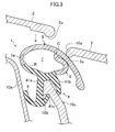
- FIGS. 1A and 1B illustrate a vehicle 10 according to a first embodiment of the present disclosure.
- the vehicle 10 includes a metal roof panel 2 covering an opening 10a in an upper portion of the vehicle 10, and a rear door panel 3 covering an opening 10b in a rear portion of the vehicle 10 such that the opening 10b can be opened or closed.
- the roof panel 2 can be replaced with another roof panel of a different type (a different material).
- the opening 10a in the upper portion of the vehicle 10 and the opening 10b in the rear portion of the vehicle 10 are continuous (see FIG. 1B ), and the roof panel 2 covering the opening 10a in the upper portion of the vehicle 10 and the rear door panel 3 covering the opening 10b in the rear portion of the vehicle 10 are arranged in parallel.
- a rear portion of the vehicle 10 located around the opening 10a in the upper portion of the vehicle 10 corresponds to a peripheral portion of the rear door panel 3 toward the front of the vehicle 10.
- a retainer 10c (near a vehicle body) is provided inside a portion of a cabin corresponding to a clearance S1 between a peripheral portion of the roof panel 2 toward the rear of the vehicle 10 and a peripheral portion of the rear door panel 3 toward the front of the vehicle 10 to extend along the clearance S1 in the vehicle width direction.
- An upper end portion of the retainer 10c includes a nail portion 10d protruding toward the front of the vehicle 10.
- a body frame 10e is provided below the roof panel 2 so as to be inclined downward toward the rear of the vehicle 10, is separated from the retainer 10c by a predetermined distance, and extends in the vehicle width direction.
- a weatherstrip 1 according to the first embodiment of the present disclosure is attached to the upper end of the retainer 10c.
- the weatherstrip 1 includes an attachment portion 4, a lip-like flexible seal wall 5, a flexible bridging wall 6, and a hollow portion 7.
- the attachment portion 4 is fitted to the retainer 10c.
- the seal wall 5 extends from an upper portion of the attachment portion 4 toward the front of the vehicle 10 (toward the interior of the cabin), is subsequently turned up, and extends toward the rear of the vehicle (toward the outside of the cabin).
- the seal wall 5 thus has a generally J-shaped cross section.
- the bridging wall 6 bridges a portion of the seal wall 5 corresponding to the clearance S1 (a portion C thereof in each of FIGS. 2-4 ) and the attachment portion 4 in a generally vertical direction.
- the hollow portion 7 is surrounded by the attachment portion 4, the seal wall 5, and the bridging wall 6.
- the attachment portion 4 has a generally U-shaped cross-sectional shape that is open downward, and includes a front wall 41 a located toward the front of the vehicle 10 and a rear wall 41b located toward the rear of the vehicle 10.
- the attachment portion 4 is made of sponge rubber that has a specific gravity of greater than or equal to about 0.6 and equal to or less than about 1.3 and contains a plurality of air bubbles, or solid rubber that has a specific gravity of greater than or equal to about 0.6 and equal to or less than about 1.3 and does not contain air bubbles.
- the sponge rubber or the solid rubber is a rubber-like elastic material of, for example, ethylene-propylene-diene copolymer (EPDM).
- a lower end portion of the front wall 41a includes a protrusion 41c protruding obliquely upward toward the rear of the vehicle 10.
- a portion of the lower end portion of the front wall 41a toward the front of the vehicle 10 (toward the interior of the cabin) includes a flexible lip portion 8.
- the lip portion 8 extends obliquely upward toward the front of the vehicle 10, and has a lower surface that contacts the body frame 10e with the attachment portion 4 fitted to the retainer 10c.
- a root portion R of the seal wall 5 connected to the attachment portion 4 is made of the same material as that of the attachment portion 4, a portion of the seal wall 5 except the root portion R is made of sponge rubber having a specific gravity of greater than or equal to about 0.4 and equal to or less than about 0.8 and containing a plurality of air bubbles.
- the sponge rubber is ethylene-propylene-diene copolymer (EPDM).
- the attachment portion 4 and the root portion R of the seal wall 5 connected to the attachment portion 4 are made of the same material, are continuous, and are designed to provide greater rigidity than the portion of the seal wall 5 except the root portion R.
- a portion of the seal wall 5 toward the front of the vehicle 10 (toward the interior of the cabin) is gently curved, and a recess 5a is formed in the inner surface (a surface toward the rear of the vehicle 10) of the portion of the seal wall 5 toward the front of the vehicle 10 to extend in the vehicle width direction.
- a portion of the seal wall 5 from a middle portion thereof toward the rear end of the vehicle 10 is gently curved such that the middle portion is above the other portions of the seal wall 5.
- a portion of the seal wall 5 toward the rear end of the vehicle 10 is thicker than the other portion thereof.
- the material of the bridging wall 6 is identical to that of the portion of the seal wall 5 except the root portion R, and the bridging wall 6 is gently curved such that a generally vertically central portion of the bridging wall 6 is located toward the rear of the vehicle 10 (outwardly of the cabin).
- the bridging wall 6 is bent such that a generally vertically central portion of the bridging wall 6 protrudes outwardly of the cabin, and a region of the bridging wall 6 around the protruding end thereof contacts a lower surface of the seal wall 5.
- the metal roof panel 2 covering the opening 10a in the upper portion of the vehicle 10 can be replaced with a glass roof panel 2 that is thicker than the metal roof panel 2.
- a lower surface 2a of a peripheral portion of the roof panel 2 toward the rear of the vehicle 10 is below the lower surface 3a of the peripheral portion of the rear door panel 3 toward the front of the vehicle 10 as illustrated in FIG. 5 .
- the seal wall 5 of the weatherstrip 1 according to the first embodiment of the present disclosure When the seal wall 5 of the weatherstrip 1 according to the first embodiment of the present disclosure is pressed from above, the seal wall 5 and the bridging wall 6 are bent downwardly. This allows the bridging wall 6 to apply an upward pressure to a portion of the seal wall 5 near the peripheral portion of the rear door panel 3.
- the root portion R of the seal wall 5 connected to the attachment portion 4 has greater rigidity than the portion of the seal wall 5 except the root portion R and the bridging wall 6, and is thus less likely to be bent. For this reason, when the seal wall 5 seals the clearance S1 between the peripheral portion of the roof panel 2 and the peripheral portion of the rear door panel 3, the phenomenon where the root portion R is bent downwardly of the seal wall 5 toward the interior of the cabin (the phenomenon called "inclination") is prevented even in a situation where the pressure acts on the seal wall 5 toward the interior of the cabin. This prevention prevents the seal wall 5 from being displaced from the location corresponding to the clearance S 1 between the peripheral portion of the roof panel 2 and the peripheral portion of the rear door panel 3 toward the interior of the vehicle, and can ensure the sealing of the clearance S1.
- the root portion R and the attachment portion 4 are made of the same material, and are continuous, the root portion R is less likely to be bent toward the front of the vehicle 10 (toward the interior of the cabin) with respect to the attachment portion 4. This makes it more difficult for the seal wall 5 to be bent downward toward the front of the vehicle 10 even with the pressure applied to the seal wall 5 toward the front of the vehicle 10 (toward the interior of the cabin), can ensure that the seal wall 5 is prevented from being displaced from the location corresponding to the clearance S1 between the peripheral portion of the roof panel 2 and the peripheral portion of the rear door panel 3 toward the front of the vehicle 10 (toward the interior of the cabin), and can improve the sealing performance at which the clearance S1 is sealed.
- a portion of the seal wall 5 including the recess 5a is thinner than the other portions thereof, and for this reason, when the pressure is applied to the seal wall 5 from above, this pressure ensures that the portion of the seal wall 5 including the recess 5a is bent. This makes it difficult for the shape of the bent seal wall 5 to vary even with the changing of the roof panel 2 to another roof panel 2 of a different type, and can reduce variations in sealing performance at which the clearance S1 between the peripheral portion of the replaceable roof panel 2 of the vehicle 10 and the peripheral portion of the rear door panel 3 is sealed.
- FIGS. 8 and 9 illustrate a weatherstrip 1 according to a second embodiment of the present disclosure.
- the structure of a portion of a seal wall 5 and the location of a lip portion 8 are merely different from those of the first embodiment, and other elements are identical to those of the first embodiment. Thus, only the difference between the first and second embodiments will now be described.
- the seal wall 5 of the second embodiment includes a first wall portion 51 and a second wall portion 52.
- the first wall portion 51 extends obliquely upwardly from an upper portion of an attachment portion 4 near the front of a vehicle 10 toward the front of the vehicle 10 (toward the interior of the cabin).
- the second wall portion 52 extends from the extending end of the first wall portion 51 toward the rear of the vehicle 10 (outwardly of the cabin).
- a recess 5c is formed in the inner surface of a portion of the seal wall 5 connecting the first wall portion 51 to the second wall portion 52.
- An acute angle ⁇ (see FIG. 8 ) is formed between a surface of a portion of the recess 5c near the first wall portion 51 and a surface of a portion of the recess 5c near the second wall portion 52.
- the lip portion 8 of the second embodiment is made of the same material as a root portion R of the seal wall 5 connected to the attachment portion 4, and extends obliquely upwardly from a surface of a generally vertically central portion of the root portion R near the front of the vehicle 10 toward the front of the vehicle 10 as illustrated in FIG. 8 .
- a lower surface of the lip portion 8 contacts a body frame 10e as illustrated in FIG. 9 .
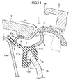
- FIGS. 10-14 illustrate a weatherstrip 1 according to a third embodiment of the present disclosure.
- the structure of a portion of a seal wall 5, the location of a bridging wall 6, the location of a lip portion 8, and the structure of a portion of a rear door panel 3 are merely different from those of the first embodiment, and other elements are identical to those of the first embodiment. Thus, only the difference between the first and third embodiments will now be described.
- the seal wall 5 of the third embodiment is semielliptic, and its middle portion is located above the other portions of the seal wall 5.
- a root portion R of the seal wall 5 connected to an attachment portion 4 extends generally horizontally in the longitudinal direction of a vehicle.
- a portion of the seal wall 5 closer to the rear door panel 3 than a portion C of the seal wall 5 is thicker than a portion of the seal wall 5 closer to a roof panel 2 than the portion C.
- a recess 5b is formed in the inner surface (a surface toward the rear of the vehicle) of a portion of the seal wall 5 toward the front of the vehicle (toward the interior of the cabin) to extend in the vehicle width direction.
- a bridging wall 6 of the third embodiment is connected to a portion of the seal wall 5 corresponding to a peripheral portion of the rear door panel 3 (the portion C in each of FIGS. 11 and 12 ).
- the lip portion 8 of the third embodiment protrudes obliquely upwardly from an end of the root portion R of the seal wall 5 connected to the attachment portion 4 near the front of a vehicle toward the front of the vehicle along the root portion R as illustrated in FIG. 10 .
- a lower surface of the lip portion 8 contacts a body frame 10e as illustrated in FIGS. 11-14 .
- a portion of the rear door panel 3 of the third embodiment closer to the rear of the vehicle than a peripheral portion of the rear door panel 3 toward the front of the vehicle has a lower surface 3b protruding downwardly so as to be located below a lower surface 3a of the peripheral portion of the rear door panel 3 toward the front of the vehicle as illustrated in FIGS. 11 and 12 .
- the lower surface 3b presses the seal wall 5 from above such that while the rear door panel 3 covers an opening 10b in an rear portion of the vehicle, a portion of the seal wall 5 closer to the rear door panel 3 than the portion C is suspended.
- a portion of the seal wall 5 connected to the bridging wall 6 (the portion C) is located to correspond to the lower surface 3a of the peripheral portion of the rear door panel 3.
- the seal wall 5 and the bridging wall 6 are bent downwardly, thereby allowing the bridging wall 6 to apply an upward pressure to a portion of the seal wall 5 near the peripheral portion of the rear door panel 3. This can prevent a clearance from being formed between the lower surface 3a of the peripheral portion of the rear door panel 3 and the weatherstrip 1.
- each of the first and second embodiments of the present disclosure is used to seal the clearance S1 between the roof panel 2 and the rear door panel 3, it can be used also to seal a clearance S 1 between a peripheral portion of a rear door panel 3 of a vehicle including the rear door panel 3 that is arranged in parallel with a roof panel 2 and a portion of the vehicle around an opening 10a in an upper portion of the vehicle.
- the material of the weatherstrip 1 is EPDM
- the material of the weatherstrip 1 is not limited to EPDM.
- the weatherstrip 1 may be made of any other rubber material or any other elastic material, such as isoprene rubber (IR), chloroprene rubber (CR), a thermoplastic elastomer (an olefinic or styrenic thermoplastic elastomer), or soft polyvinyl chloride.
- the seal wall 5 is made of sponge rubber containing a plurality of air bubbles
- the material of the seal wall 5 is not limited to the sponge rubber.
- the seal wall 5 may be made of, for example, solid rubber that does not contain air bubbles.
- the present disclosure is suitable for a weatherstrip sealing the clearance between a peripheral portion of a roof panel covering an opening in an upper portion of a vehicle and a portion of the vehicle around the opening in the upper portion of the vehicle.
Landscapes
- Engineering & Computer Science (AREA)
- Mechanical Engineering (AREA)
- Seal Device For Vehicle (AREA)
- Body Structure For Vehicles (AREA)
Applications Claiming Priority (1)
| Application Number | Priority Date | Filing Date | Title |
|---|---|---|---|
| JP2013194557A JP6242639B2 (ja) | 2013-09-19 | 2013-09-19 | ウェザストリップ |
Publications (3)
| Publication Number | Publication Date |
|---|---|
| EP2851226A2 true EP2851226A2 (fr) | 2015-03-25 |
| EP2851226A3 EP2851226A3 (fr) | 2015-04-08 |
| EP2851226B1 EP2851226B1 (fr) | 2019-01-16 |
Family
ID=51589076
Family Applications (1)
| Application Number | Title | Priority Date | Filing Date |
|---|---|---|---|
| EP14184031.4A Active EP2851226B1 (fr) | 2013-09-19 | 2014-09-09 | Joint d'étanchéité |
Country Status (4)
| Country | Link |
|---|---|
| US (1) | US9415670B2 (fr) |
| EP (1) | EP2851226B1 (fr) |
| JP (1) | JP6242639B2 (fr) |
| CN (1) | CN104442323B (fr) |
Families Citing this family (11)
| Publication number | Priority date | Publication date | Assignee | Title |
|---|---|---|---|---|
| JP2017024432A (ja) * | 2015-07-15 | 2017-02-02 | アイシン精機株式会社 | サンルーフ装置のウエザストリップ |
| FR3044605B1 (fr) * | 2015-12-02 | 2019-07-19 | Renault S.A.S | Porte de vehicule automobile comprenant un joint d'etancheite. |
| JP6681193B2 (ja) * | 2015-12-28 | 2020-04-15 | 西川ゴム工業株式会社 | 見切りシール及び見切り部のシール構造 |
| DE102017120233A1 (de) * | 2016-09-05 | 2018-03-08 | Nishikawa Rubber Co., Ltd. | Dichtungsstreifen für kraftfahrzeug |
| JP7073279B2 (ja) * | 2017-01-11 | 2022-05-23 | 日本板硝子株式会社 | ガラス板モジュール |
| US10358020B2 (en) | 2017-09-18 | 2019-07-23 | Honda Motor Co., Ltd. | Sunroof seal assembly and method for a vehicle |
| WO2019148937A1 (fr) * | 2018-01-30 | 2019-08-08 | 佛山市顺德区美的洗涤电器制造有限公司 | Bande d'étanchéité pour lave-vaisselle et lave-vaisselle comprenant celle-ci |
| JP7097190B2 (ja) * | 2018-02-19 | 2022-07-07 | 西川ゴム工業株式会社 | 自動車用ウェザーストリップ |
| US11376939B2 (en) * | 2018-06-19 | 2022-07-05 | Faraday&Future Inc. | Vehicular seal carrier system |
| JP6982029B2 (ja) * | 2019-07-04 | 2021-12-17 | 本田技研工業株式会社 | 車両用ドアシール材 |
| US20240166038A1 (en) * | 2022-11-18 | 2024-05-23 | Rivian Ip Holdings, Llc | Tonneau cover |
Citations (1)
| Publication number | Priority date | Publication date | Assignee | Title |
|---|---|---|---|---|
| JP2010260393A (ja) | 2009-04-30 | 2010-11-18 | Toyoda Gosei Co Ltd | 自動車用ルーフウエザストリップ |
Family Cites Families (47)
| Publication number | Priority date | Publication date | Assignee | Title |
|---|---|---|---|---|
| US4381115A (en) * | 1980-03-31 | 1983-04-26 | Nishikawa Rubber Co., Ltd. | Door weather-strip |
| DE3016237A1 (de) * | 1980-04-26 | 1981-10-29 | Volkswagenwerk Ag, 3180 Wolfsburg | Dichtungsanordnung |
| JPS5830734Y2 (ja) * | 1980-07-10 | 1983-07-07 | ダイキヨ−・ペパスト株式会社 | 開閉自在な天井窓の防水構造 |
| DE3103535A1 (de) * | 1981-02-03 | 1982-09-23 | Volkswagenwerk Ag, 3180 Wolfsburg | "dichtung fuer eine beweglich angeordnete fensterscheibe" |
| DE3119366A1 (de) * | 1981-05-15 | 1983-01-27 | Bayerische Motoren Werke AG, 8000 München | Kraftfahrzeug, insbesondere personenkraftwagen, mit wenigstens einer aussenhautbuendigen fensterscheibe |
| GB2160920B (en) * | 1984-06-26 | 1987-10-14 | Draftex Ind Ltd | Sealing strip |
| JPH0757575B2 (ja) * | 1989-12-28 | 1995-06-21 | 鬼怒川ゴム工業株式会社 | 自動車用ウエザーストリップ |
| JPH04166415A (ja) * | 1990-10-29 | 1992-06-12 | Kinugawa Rubber Ind Co Ltd | 自動車用ウエザーストリップ |
| DE4112256C3 (de) * | 1991-04-15 | 1998-06-18 | Parat Werk Schoenenbach Gmbh | Klapp- bzw. Faltverdeck für Fahrzeuge wie Cabriolets o. dgl. |
| IT1260042B (it) * | 1992-03-26 | 1996-03-28 | Zani Srl | Perfezionamento a dispositivi di azionamento per tettucci |
| JPH0784162A (ja) * | 1993-09-13 | 1995-03-31 | Hitachi Ltd | 光素子の実装構造体及びその実装法 |
| US5860692A (en) * | 1994-09-28 | 1999-01-19 | Toyoda Gosei Co., Ltd. | Weather strip for motor vehicle and method for manufacturing the same |
| DE4441671C1 (de) * | 1994-11-23 | 1995-11-16 | Porsche Ag | Faltverdeck für Fahrzeuge, insbesondere Personenkraftwagen |
| DE19702336A1 (de) * | 1997-01-23 | 1998-07-30 | Webasto Karosseriesysteme | Öffnungsfähiges Fahrzeugdach |
| US5950366A (en) * | 1997-04-21 | 1999-09-14 | General Motors Corporation | Seal structure for removable roof |
| DE19801870C2 (de) * | 1998-01-20 | 2001-09-27 | Porsche Ag | Dichtungseinrichtung für zumindest eine rahmenlose Sichtscheibe eines Kraftfahrzeuges |
| DE19924792C1 (de) * | 1999-05-29 | 2000-08-10 | Webasto Vehicle Sys Int Gmbh | Fahrzeugdach mit wenigstens zwei ausstellbaren und verschiebbaren starren Deckelelementen |
| DE19946925C2 (de) * | 1999-09-30 | 2003-07-17 | Cts Fahrzeug Dachsysteme Gmbh | Dichtelement für ein Fahrzeugdach mit einer Dachöffnung |
| JP3749103B2 (ja) * | 2000-09-27 | 2006-02-22 | 豊田合成株式会社 | 自動車用ウエザストリップのシール構造 |
| DE10051436B4 (de) * | 2000-10-17 | 2004-06-17 | Webasto Vehicle Systems International Gmbh | Dichtungsvorrichtung für ein Dachteil eines Fahrzeugdaches |
| DE20111998U1 (de) * | 2001-07-19 | 2002-08-29 | Meteor Gummiwerke K. H. Bädje GmbH & Co, 31167 Bockenem | Fensterdichtungsprofil für ein Kabriolett |
| DE10137032C1 (de) * | 2001-07-30 | 2003-01-30 | Daimler Chrysler Ag | Dichtungsanordnung für ein Klappdach eines Hardtop-Fahrzeugs |
| SE522716C2 (sv) * | 2001-12-18 | 2004-03-02 | Accra Teknik Ab | A-stolpe och ett tätningsförsett taksidoparti hos ett fordon med en dörr utan fönsterram |
| JP4032303B2 (ja) * | 2003-02-14 | 2008-01-16 | 豊田合成株式会社 | 自動車用ウエザストリップ |
| JP4147964B2 (ja) * | 2003-02-10 | 2008-09-10 | 豊田合成株式会社 | 自動車用ウエザストリップ |
| US20040182010A1 (en) * | 2003-03-21 | 2004-09-23 | Wilfried Kalb | Seal element for a movable vehicle component |
| JP4032250B2 (ja) | 2003-06-04 | 2008-01-16 | 豊田合成株式会社 | 自動車用スライディングルーフのシール構造 |
| DE10350675A1 (de) * | 2003-10-30 | 2005-06-16 | Daimlerchrysler Ag | A-Säule eines Kraftfahrzeugs |
| DE102004017328B4 (de) * | 2004-04-06 | 2006-05-11 | Cts Fahrzeug-Dachsysteme Gmbh | Dichtungsanordnung für ein verstellbares Fahrzeugdach |
| DE102005033276B3 (de) * | 2005-07-15 | 2006-10-19 | Webasto Ag | Dachaufbau mit einem Dachausschnitt und Dichtung hierfür |
| JP4647450B2 (ja) | 2005-09-27 | 2011-03-09 | 豊田合成株式会社 | ウエザストリップ |
| DE102005060976B4 (de) | 2005-12-20 | 2011-02-24 | Metzeler Automotive Profile Systems Gmbh | Dichtung zum Abdichten eines Spalts zwischen einem ersten Bauteil und einem zweiten Bauteil, insbesondere im Bereich des Dachs eines Kraftfahrzeugs |
| JP4784825B2 (ja) * | 2006-04-24 | 2011-10-05 | 豊田合成株式会社 | 自動車用ウエザストリップ |
| JP2008087495A (ja) * | 2006-09-29 | 2008-04-17 | Toyoda Gosei Co Ltd | 自動車用ウエザストリップ |
| US20080229670A1 (en) * | 2007-03-15 | 2008-09-25 | Toyoda Gosei Co., Ltd. | Weather strip |
| DE102008020936B4 (de) * | 2007-04-27 | 2016-11-10 | Toyoda Gosei Co., Ltd. | Dichtungsstreifen und Herstellungsverfahren für diesen |
| JP2010532293A (ja) * | 2007-06-29 | 2010-10-07 | クーパー−スタンダード・オートモーティブ・インコーポレーテッド | 内側ガーニッシュ組立体モジュールシステム |
| JP5152664B2 (ja) * | 2007-09-20 | 2013-02-27 | 豊田合成株式会社 | 自動車用ウエザストリップ |
| CN201280883Y (zh) * | 2008-09-11 | 2009-07-29 | 比亚迪股份有限公司 | 车门组件 |
| CN101428550A (zh) * | 2008-12-08 | 2009-05-13 | 伟巴斯特车顶供暖系统(上海)有限公司 | 汽车天窗玻璃总成 |
| JP5152118B2 (ja) * | 2009-07-08 | 2013-02-27 | 豊田合成株式会社 | ウエザストリップ |
| JP5207554B2 (ja) * | 2009-08-31 | 2013-06-12 | 豊田合成株式会社 | 自動車用ルーフウエザストリップ |
| ITBO20110476A1 (it) * | 2011-08-01 | 2013-02-02 | Ferrari Spa | Automobile con un tetto apribile provvista di montanti verticali interni ed esterni |
| DE102012101694A1 (de) * | 2012-03-01 | 2013-09-05 | Webasto Ag | Schiebedachsystem mit Dichtungsanordnung |
| DE102013108081A1 (de) * | 2013-07-29 | 2015-01-29 | Roof Systems Germany Gmbh | Dachkonstruktion für ein Kraftfahrzeug und Kraftfahrzeug-Rohbaukarosserie |
| WO2015131186A1 (fr) * | 2014-02-28 | 2015-09-03 | Fca Us Llc | Dispositif de blocage à vide |
| JP6237390B2 (ja) * | 2014-03-26 | 2017-11-29 | 豊田合成株式会社 | センターピラーウエザストリップ |
-
2013
- 2013-09-19 JP JP2013194557A patent/JP6242639B2/ja active Active
-
2014
- 2014-09-08 US US14/479,975 patent/US9415670B2/en active Active
- 2014-09-09 EP EP14184031.4A patent/EP2851226B1/fr active Active
- 2014-09-12 CN CN201410462627.9A patent/CN104442323B/zh active Active
Patent Citations (1)
| Publication number | Priority date | Publication date | Assignee | Title |
|---|---|---|---|---|
| JP2010260393A (ja) | 2009-04-30 | 2010-11-18 | Toyoda Gosei Co Ltd | 自動車用ルーフウエザストリップ |
Also Published As
| Publication number | Publication date |
|---|---|
| US9415670B2 (en) | 2016-08-16 |
| CN104442323A (zh) | 2015-03-25 |
| JP6242639B2 (ja) | 2017-12-06 |
| CN104442323B (zh) | 2018-11-13 |
| US20150076856A1 (en) | 2015-03-19 |
| JP2015058843A (ja) | 2015-03-30 |
| EP2851226A3 (fr) | 2015-04-08 |
| EP2851226B1 (fr) | 2019-01-16 |
Similar Documents
| Publication | Publication Date | Title |
|---|---|---|
| EP2851226B1 (fr) | Joint d'étanchéité | |
| CN205970791U (zh) | 汽车车门用嵌条的安装构造 | |
| US10549618B2 (en) | Weather strip | |
| US10279667B2 (en) | Seal for automobile door | |
| US9845001B1 (en) | Glass run for automobile door | |
| US10611223B2 (en) | Glass run for automobile door | |
| CN108569123B (zh) | 玻璃滑槽 | |
| US20070271853A1 (en) | Glass run mounting structure | |
| CN107031360A (zh) | 车门密封结构 | |
| CN107627823A (zh) | 玻璃导槽 | |
| JP6059925B2 (ja) | ドアウエザストリップ | |
| JP6390967B2 (ja) | オープニングトリムウエザストリップ | |
| JP4453549B2 (ja) | 車両用ドアのシール構造 | |
| JP5790613B2 (ja) | ガラスラン | |
| US20230132871A1 (en) | Vehicle molding | |
| KR20160054996A (ko) | 차량용 글래스 런 | |
| JP2010234998A (ja) | ドアウエザストリップの取付構造 | |
| JP5085409B2 (ja) | ウェザストリップの取付構造 | |
| JP2010047157A (ja) | 自動車用ウエザストリップ | |
| JP2011025855A (ja) | 自動車用ドアの吸い出され防止構造 | |
| JP5521958B2 (ja) | 自動車用ウエザストリップ | |
| JP4997046B2 (ja) | シール構造 | |
| JP2006335110A (ja) | ガラスラン | |
| JP2009078664A (ja) | オープニングトリムウエザストリップ | |
| JP2017039410A (ja) | 車両のドア構造 |
Legal Events
| Date | Code | Title | Description |
|---|---|---|---|
| PUAL | Search report despatched |
Free format text: ORIGINAL CODE: 0009013 |
|
| PUAI | Public reference made under article 153(3) epc to a published international application that has entered the european phase |
Free format text: ORIGINAL CODE: 0009012 |
|
| 17P | Request for examination filed |
Effective date: 20140909 |
|
| AK | Designated contracting states |
Kind code of ref document: A2 Designated state(s): AL AT BE BG CH CY CZ DE DK EE ES FI FR GB GR HR HU IE IS IT LI LT LU LV MC MK MT NL NO PL PT RO RS SE SI SK SM TR |
|
| AX | Request for extension of the european patent |
Extension state: BA ME |
|
| AK | Designated contracting states |
Kind code of ref document: A3 Designated state(s): AL AT BE BG CH CY CZ DE DK EE ES FI FR GB GR HR HU IE IS IT LI LT LU LV MC MK MT NL NO PL PT RO RS SE SI SK SM TR |
|
| AX | Request for extension of the european patent |
Extension state: BA ME |
|
| RIC1 | Information provided on ipc code assigned before grant |
Ipc: B60J 10/12 20060101ALI20150303BHEP Ipc: B60J 10/00 20060101AFI20150303BHEP |
|
| R17P | Request for examination filed (corrected) |
Effective date: 20151002 |
|
| RBV | Designated contracting states (corrected) |
Designated state(s): AL AT BE BG CH CY CZ DE DK EE ES FI FR GB GR HR HU IE IS IT LI LT LU LV MC MK MT NL NO PL PT RO RS SE SI SK SM TR |
|
| REG | Reference to a national code |
Ref country code: DE Ref legal event code: R079 Ref document number: 602014039920 Country of ref document: DE Free format text: PREVIOUS MAIN CLASS: B60J0010000000 Ipc: B60J0010160000 |
|
| GRAP | Despatch of communication of intention to grant a patent |
Free format text: ORIGINAL CODE: EPIDOSNIGR1 |
|
| STAA | Information on the status of an ep patent application or granted ep patent |
Free format text: STATUS: GRANT OF PATENT IS INTENDED |
|
| RIC1 | Information provided on ipc code assigned before grant |
Ipc: B60J 10/32 20160101ALI20180905BHEP Ipc: B60J 10/82 20160101ALI20180905BHEP Ipc: B60J 10/16 20160101AFI20180905BHEP Ipc: B60J 10/277 20160101ALI20180905BHEP Ipc: B60J 10/24 20160101ALI20180905BHEP |
|
| INTG | Intention to grant announced |
Effective date: 20180928 |
|
| GRAS | Grant fee paid |
Free format text: ORIGINAL CODE: EPIDOSNIGR3 |
|
| GRAA | (expected) grant |
Free format text: ORIGINAL CODE: 0009210 |
|
| STAA | Information on the status of an ep patent application or granted ep patent |
Free format text: STATUS: THE PATENT HAS BEEN GRANTED |
|
| AK | Designated contracting states |
Kind code of ref document: B1 Designated state(s): AL AT BE BG CH CY CZ DE DK EE ES FI FR GB GR HR HU IE IS IT LI LT LU LV MC MK MT NL NO PL PT RO RS SE SI SK SM TR |
|
| REG | Reference to a national code |
Ref country code: GB Ref legal event code: FG4D |
|
| REG | Reference to a national code |
Ref country code: CH Ref legal event code: EP |
|
| REG | Reference to a national code |
Ref country code: IE Ref legal event code: FG4D |
|
| REG | Reference to a national code |
Ref country code: DE Ref legal event code: R096 Ref document number: 602014039920 Country of ref document: DE |
|
| REG | Reference to a national code |
Ref country code: AT Ref legal event code: REF Ref document number: 1089457 Country of ref document: AT Kind code of ref document: T Effective date: 20190215 |
|
| REG | Reference to a national code |
Ref country code: NL Ref legal event code: MP Effective date: 20190116 |
|
| REG | Reference to a national code |
Ref country code: LT Ref legal event code: MG4D |
|
| PG25 | Lapsed in a contracting state [announced via postgrant information from national office to epo] |
Ref country code: NL Free format text: LAPSE BECAUSE OF FAILURE TO SUBMIT A TRANSLATION OF THE DESCRIPTION OR TO PAY THE FEE WITHIN THE PRESCRIBED TIME-LIMIT Effective date: 20190116 |
|
| REG | Reference to a national code |
Ref country code: AT Ref legal event code: MK05 Ref document number: 1089457 Country of ref document: AT Kind code of ref document: T Effective date: 20190116 |
|
| PG25 | Lapsed in a contracting state [announced via postgrant information from national office to epo] |
Ref country code: ES Free format text: LAPSE BECAUSE OF FAILURE TO SUBMIT A TRANSLATION OF THE DESCRIPTION OR TO PAY THE FEE WITHIN THE PRESCRIBED TIME-LIMIT Effective date: 20190116 Ref country code: PT Free format text: LAPSE BECAUSE OF FAILURE TO SUBMIT A TRANSLATION OF THE DESCRIPTION OR TO PAY THE FEE WITHIN THE PRESCRIBED TIME-LIMIT Effective date: 20190516 Ref country code: SE Free format text: LAPSE BECAUSE OF FAILURE TO SUBMIT A TRANSLATION OF THE DESCRIPTION OR TO PAY THE FEE WITHIN THE PRESCRIBED TIME-LIMIT Effective date: 20190116 Ref country code: NO Free format text: LAPSE BECAUSE OF FAILURE TO SUBMIT A TRANSLATION OF THE DESCRIPTION OR TO PAY THE FEE WITHIN THE PRESCRIBED TIME-LIMIT Effective date: 20190416 Ref country code: FI Free format text: LAPSE BECAUSE OF FAILURE TO SUBMIT A TRANSLATION OF THE DESCRIPTION OR TO PAY THE FEE WITHIN THE PRESCRIBED TIME-LIMIT Effective date: 20190116 Ref country code: PL Free format text: LAPSE BECAUSE OF FAILURE TO SUBMIT A TRANSLATION OF THE DESCRIPTION OR TO PAY THE FEE WITHIN THE PRESCRIBED TIME-LIMIT Effective date: 20190116 Ref country code: LT Free format text: LAPSE BECAUSE OF FAILURE TO SUBMIT A TRANSLATION OF THE DESCRIPTION OR TO PAY THE FEE WITHIN THE PRESCRIBED TIME-LIMIT Effective date: 20190116 |
|
| PG25 | Lapsed in a contracting state [announced via postgrant information from national office to epo] |
Ref country code: BG Free format text: LAPSE BECAUSE OF FAILURE TO SUBMIT A TRANSLATION OF THE DESCRIPTION OR TO PAY THE FEE WITHIN THE PRESCRIBED TIME-LIMIT Effective date: 20190416 Ref country code: GR Free format text: LAPSE BECAUSE OF FAILURE TO SUBMIT A TRANSLATION OF THE DESCRIPTION OR TO PAY THE FEE WITHIN THE PRESCRIBED TIME-LIMIT Effective date: 20190417 Ref country code: HR Free format text: LAPSE BECAUSE OF FAILURE TO SUBMIT A TRANSLATION OF THE DESCRIPTION OR TO PAY THE FEE WITHIN THE PRESCRIBED TIME-LIMIT Effective date: 20190116 Ref country code: RS Free format text: LAPSE BECAUSE OF FAILURE TO SUBMIT A TRANSLATION OF THE DESCRIPTION OR TO PAY THE FEE WITHIN THE PRESCRIBED TIME-LIMIT Effective date: 20190116 Ref country code: IS Free format text: LAPSE BECAUSE OF FAILURE TO SUBMIT A TRANSLATION OF THE DESCRIPTION OR TO PAY THE FEE WITHIN THE PRESCRIBED TIME-LIMIT Effective date: 20190516 Ref country code: LV Free format text: LAPSE BECAUSE OF FAILURE TO SUBMIT A TRANSLATION OF THE DESCRIPTION OR TO PAY THE FEE WITHIN THE PRESCRIBED TIME-LIMIT Effective date: 20190116 |
|
| REG | Reference to a national code |
Ref country code: DE Ref legal event code: R097 Ref document number: 602014039920 Country of ref document: DE |
|
| PG25 | Lapsed in a contracting state [announced via postgrant information from national office to epo] |
Ref country code: RO Free format text: LAPSE BECAUSE OF FAILURE TO SUBMIT A TRANSLATION OF THE DESCRIPTION OR TO PAY THE FEE WITHIN THE PRESCRIBED TIME-LIMIT Effective date: 20190116 Ref country code: IT Free format text: LAPSE BECAUSE OF FAILURE TO SUBMIT A TRANSLATION OF THE DESCRIPTION OR TO PAY THE FEE WITHIN THE PRESCRIBED TIME-LIMIT Effective date: 20190116 Ref country code: CZ Free format text: LAPSE BECAUSE OF FAILURE TO SUBMIT A TRANSLATION OF THE DESCRIPTION OR TO PAY THE FEE WITHIN THE PRESCRIBED TIME-LIMIT Effective date: 20190116 Ref country code: SK Free format text: LAPSE BECAUSE OF FAILURE TO SUBMIT A TRANSLATION OF THE DESCRIPTION OR TO PAY THE FEE WITHIN THE PRESCRIBED TIME-LIMIT Effective date: 20190116 Ref country code: EE Free format text: LAPSE BECAUSE OF FAILURE TO SUBMIT A TRANSLATION OF THE DESCRIPTION OR TO PAY THE FEE WITHIN THE PRESCRIBED TIME-LIMIT Effective date: 20190116 Ref country code: DK Free format text: LAPSE BECAUSE OF FAILURE TO SUBMIT A TRANSLATION OF THE DESCRIPTION OR TO PAY THE FEE WITHIN THE PRESCRIBED TIME-LIMIT Effective date: 20190116 Ref country code: AT Free format text: LAPSE BECAUSE OF FAILURE TO SUBMIT A TRANSLATION OF THE DESCRIPTION OR TO PAY THE FEE WITHIN THE PRESCRIBED TIME-LIMIT Effective date: 20190116 Ref country code: AL Free format text: LAPSE BECAUSE OF FAILURE TO SUBMIT A TRANSLATION OF THE DESCRIPTION OR TO PAY THE FEE WITHIN THE PRESCRIBED TIME-LIMIT Effective date: 20190116 |
|
| PLBE | No opposition filed within time limit |
Free format text: ORIGINAL CODE: 0009261 |
|
| STAA | Information on the status of an ep patent application or granted ep patent |
Free format text: STATUS: NO OPPOSITION FILED WITHIN TIME LIMIT |
|
| PG25 | Lapsed in a contracting state [announced via postgrant information from national office to epo] |
Ref country code: SM Free format text: LAPSE BECAUSE OF FAILURE TO SUBMIT A TRANSLATION OF THE DESCRIPTION OR TO PAY THE FEE WITHIN THE PRESCRIBED TIME-LIMIT Effective date: 20190116 |
|
| 26N | No opposition filed |
Effective date: 20191017 |
|
| PG25 | Lapsed in a contracting state [announced via postgrant information from national office to epo] |
Ref country code: SI Free format text: LAPSE BECAUSE OF FAILURE TO SUBMIT A TRANSLATION OF THE DESCRIPTION OR TO PAY THE FEE WITHIN THE PRESCRIBED TIME-LIMIT Effective date: 20190116 |
|
| PG25 | Lapsed in a contracting state [announced via postgrant information from national office to epo] |
Ref country code: TR Free format text: LAPSE BECAUSE OF FAILURE TO SUBMIT A TRANSLATION OF THE DESCRIPTION OR TO PAY THE FEE WITHIN THE PRESCRIBED TIME-LIMIT Effective date: 20190116 |
|
| PG25 | Lapsed in a contracting state [announced via postgrant information from national office to epo] |
Ref country code: MC Free format text: LAPSE BECAUSE OF FAILURE TO SUBMIT A TRANSLATION OF THE DESCRIPTION OR TO PAY THE FEE WITHIN THE PRESCRIBED TIME-LIMIT Effective date: 20190116 |
|
| REG | Reference to a national code |
Ref country code: CH Ref legal event code: PL |
|
| PG25 | Lapsed in a contracting state [announced via postgrant information from national office to epo] |
Ref country code: LU Free format text: LAPSE BECAUSE OF NON-PAYMENT OF DUE FEES Effective date: 20190909 Ref country code: LI Free format text: LAPSE BECAUSE OF NON-PAYMENT OF DUE FEES Effective date: 20190930 Ref country code: IE Free format text: LAPSE BECAUSE OF NON-PAYMENT OF DUE FEES Effective date: 20190909 Ref country code: CH Free format text: LAPSE BECAUSE OF NON-PAYMENT OF DUE FEES Effective date: 20190930 |
|
| REG | Reference to a national code |
Ref country code: BE Ref legal event code: MM Effective date: 20190930 |
|
| PG25 | Lapsed in a contracting state [announced via postgrant information from national office to epo] |
Ref country code: BE Free format text: LAPSE BECAUSE OF NON-PAYMENT OF DUE FEES Effective date: 20190930 |
|
| PG25 | Lapsed in a contracting state [announced via postgrant information from national office to epo] |
Ref country code: FR Free format text: LAPSE BECAUSE OF NON-PAYMENT OF DUE FEES Effective date: 20190930 |
|
| PG25 | Lapsed in a contracting state [announced via postgrant information from national office to epo] |
Ref country code: CY Free format text: LAPSE BECAUSE OF FAILURE TO SUBMIT A TRANSLATION OF THE DESCRIPTION OR TO PAY THE FEE WITHIN THE PRESCRIBED TIME-LIMIT Effective date: 20190116 |
|
| PG25 | Lapsed in a contracting state [announced via postgrant information from national office to epo] |
Ref country code: MT Free format text: LAPSE BECAUSE OF FAILURE TO SUBMIT A TRANSLATION OF THE DESCRIPTION OR TO PAY THE FEE WITHIN THE PRESCRIBED TIME-LIMIT Effective date: 20190116 Ref country code: HU Free format text: LAPSE BECAUSE OF FAILURE TO SUBMIT A TRANSLATION OF THE DESCRIPTION OR TO PAY THE FEE WITHIN THE PRESCRIBED TIME-LIMIT; INVALID AB INITIO Effective date: 20140909 |
|
| PG25 | Lapsed in a contracting state [announced via postgrant information from national office to epo] |
Ref country code: MK Free format text: LAPSE BECAUSE OF FAILURE TO SUBMIT A TRANSLATION OF THE DESCRIPTION OR TO PAY THE FEE WITHIN THE PRESCRIBED TIME-LIMIT Effective date: 20190116 |
|
| PGFP | Annual fee paid to national office [announced via postgrant information from national office to epo] |
Ref country code: DE Payment date: 20250730 Year of fee payment: 12 |
|
| PGFP | Annual fee paid to national office [announced via postgrant information from national office to epo] |
Ref country code: GB Payment date: 20250731 Year of fee payment: 12 |