EP2851245A1 - Verrouillage de direction mécanique pour véhicules - Google Patents
Verrouillage de direction mécanique pour véhicules Download PDFInfo
- Publication number
- EP2851245A1 EP2851245A1 EP14184936.4A EP14184936A EP2851245A1 EP 2851245 A1 EP2851245 A1 EP 2851245A1 EP 14184936 A EP14184936 A EP 14184936A EP 2851245 A1 EP2851245 A1 EP 2851245A1
- Authority
- EP
- European Patent Office
- Prior art keywords
- lock
- locking bolt
- locking
- lock cylinder
- mechanical
- Prior art date
- Legal status (The legal status is an assumption and is not a legal conclusion. Google has not performed a legal analysis and makes no representation as to the accuracy of the status listed.)
- Granted
Links
- 230000008878 coupling Effects 0.000 claims description 17
- 238000010168 coupling process Methods 0.000 claims description 17
- 238000005859 coupling reaction Methods 0.000 claims description 17
- 230000007246 mechanism Effects 0.000 claims description 11
- 238000001514 detection method Methods 0.000 claims description 4
- 239000007858 starting material Substances 0.000 description 6
- 230000004048 modification Effects 0.000 description 3
- 238000012986 modification Methods 0.000 description 3
- 238000003780 insertion Methods 0.000 description 2
- 230000037431 insertion Effects 0.000 description 2
- 238000004519 manufacturing process Methods 0.000 description 2
- 230000036316 preload Effects 0.000 description 2
- 230000006835 compression Effects 0.000 description 1
- 238000007906 compression Methods 0.000 description 1
- 230000001419 dependent effect Effects 0.000 description 1
- 239000000446 fuel Substances 0.000 description 1
- 230000000750 progressive effect Effects 0.000 description 1
- 238000005096 rolling process Methods 0.000 description 1
- 230000001960 triggered effect Effects 0.000 description 1
- 210000000707 wrist Anatomy 0.000 description 1
Images

Classifications
-
- B—PERFORMING OPERATIONS; TRANSPORTING
- B60—VEHICLES IN GENERAL
- B60R—VEHICLES, VEHICLE FITTINGS, OR VEHICLE PARTS, NOT OTHERWISE PROVIDED FOR
- B60R25/00—Fittings or systems for preventing or indicating unauthorised use or theft of vehicles
- B60R25/01—Fittings or systems for preventing or indicating unauthorised use or theft of vehicles operating on vehicle systems or fittings, e.g. on doors, seats or windscreens
- B60R25/02—Fittings or systems for preventing or indicating unauthorised use or theft of vehicles operating on vehicle systems or fittings, e.g. on doors, seats or windscreens operating on the steering mechanism
- B60R25/021—Fittings or systems for preventing or indicating unauthorised use or theft of vehicles operating on vehicle systems or fittings, e.g. on doors, seats or windscreens operating on the steering mechanism restraining movement of the steering column or steering wheel hub, e.g. restraining means controlled by ignition switch
-
- B—PERFORMING OPERATIONS; TRANSPORTING
- B60—VEHICLES IN GENERAL
- B60R—VEHICLES, VEHICLE FITTINGS, OR VEHICLE PARTS, NOT OTHERWISE PROVIDED FOR
- B60R25/00—Fittings or systems for preventing or indicating unauthorised use or theft of vehicles
- B60R25/01—Fittings or systems for preventing or indicating unauthorised use or theft of vehicles operating on vehicle systems or fittings, e.g. on doors, seats or windscreens
- B60R25/02—Fittings or systems for preventing or indicating unauthorised use or theft of vehicles operating on vehicle systems or fittings, e.g. on doors, seats or windscreens operating on the steering mechanism
- B60R25/021—Fittings or systems for preventing or indicating unauthorised use or theft of vehicles operating on vehicle systems or fittings, e.g. on doors, seats or windscreens operating on the steering mechanism restraining movement of the steering column or steering wheel hub, e.g. restraining means controlled by ignition switch
- B60R25/0211—Fittings or systems for preventing or indicating unauthorised use or theft of vehicles operating on vehicle systems or fittings, e.g. on doors, seats or windscreens operating on the steering mechanism restraining movement of the steering column or steering wheel hub, e.g. restraining means controlled by ignition switch comprising a locking member radially and linearly moved towards the steering column
- B60R25/02115—Fittings or systems for preventing or indicating unauthorised use or theft of vehicles operating on vehicle systems or fittings, e.g. on doors, seats or windscreens operating on the steering mechanism restraining movement of the steering column or steering wheel hub, e.g. restraining means controlled by ignition switch comprising a locking member radially and linearly moved towards the steering column key actuated
- B60R25/02118—Fittings or systems for preventing or indicating unauthorised use or theft of vehicles operating on vehicle systems or fittings, e.g. on doors, seats or windscreens operating on the steering mechanism restraining movement of the steering column or steering wheel hub, e.g. restraining means controlled by ignition switch comprising a locking member radially and linearly moved towards the steering column key actuated with linear bolt motion parallel to the lock axis
- B60R25/02121—Fittings or systems for preventing or indicating unauthorised use or theft of vehicles operating on vehicle systems or fittings, e.g. on doors, seats or windscreens operating on the steering mechanism restraining movement of the steering column or steering wheel hub, e.g. restraining means controlled by ignition switch comprising a locking member radially and linearly moved towards the steering column key actuated with linear bolt motion parallel to the lock axis comprising safety devices avoiding locking until removal of the key
-
- B—PERFORMING OPERATIONS; TRANSPORTING
- B60—VEHICLES IN GENERAL
- B60R—VEHICLES, VEHICLE FITTINGS, OR VEHICLE PARTS, NOT OTHERWISE PROVIDED FOR
- B60R25/00—Fittings or systems for preventing or indicating unauthorised use or theft of vehicles
- B60R25/01—Fittings or systems for preventing or indicating unauthorised use or theft of vehicles operating on vehicle systems or fittings, e.g. on doors, seats or windscreens
- B60R25/02—Fittings or systems for preventing or indicating unauthorised use or theft of vehicles operating on vehicle systems or fittings, e.g. on doors, seats or windscreens operating on the steering mechanism
- B60R25/021—Fittings or systems for preventing or indicating unauthorised use or theft of vehicles operating on vehicle systems or fittings, e.g. on doors, seats or windscreens operating on the steering mechanism restraining movement of the steering column or steering wheel hub, e.g. restraining means controlled by ignition switch
- B60R25/0211—Fittings or systems for preventing or indicating unauthorised use or theft of vehicles operating on vehicle systems or fittings, e.g. on doors, seats or windscreens operating on the steering mechanism restraining movement of the steering column or steering wheel hub, e.g. restraining means controlled by ignition switch comprising a locking member radially and linearly moved towards the steering column
- B60R25/02115—Fittings or systems for preventing or indicating unauthorised use or theft of vehicles operating on vehicle systems or fittings, e.g. on doors, seats or windscreens operating on the steering mechanism restraining movement of the steering column or steering wheel hub, e.g. restraining means controlled by ignition switch comprising a locking member radially and linearly moved towards the steering column key actuated
- B60R25/02118—Fittings or systems for preventing or indicating unauthorised use or theft of vehicles operating on vehicle systems or fittings, e.g. on doors, seats or windscreens operating on the steering mechanism restraining movement of the steering column or steering wheel hub, e.g. restraining means controlled by ignition switch comprising a locking member radially and linearly moved towards the steering column key actuated with linear bolt motion parallel to the lock axis
-
- B—PERFORMING OPERATIONS; TRANSPORTING
- B60—VEHICLES IN GENERAL
- B60R—VEHICLES, VEHICLE FITTINGS, OR VEHICLE PARTS, NOT OTHERWISE PROVIDED FOR
- B60R25/00—Fittings or systems for preventing or indicating unauthorised use or theft of vehicles
- B60R25/01—Fittings or systems for preventing or indicating unauthorised use or theft of vehicles operating on vehicle systems or fittings, e.g. on doors, seats or windscreens
- B60R25/02—Fittings or systems for preventing or indicating unauthorised use or theft of vehicles operating on vehicle systems or fittings, e.g. on doors, seats or windscreens operating on the steering mechanism
- B60R25/021—Fittings or systems for preventing or indicating unauthorised use or theft of vehicles operating on vehicle systems or fittings, e.g. on doors, seats or windscreens operating on the steering mechanism restraining movement of the steering column or steering wheel hub, e.g. restraining means controlled by ignition switch
- B60R25/02147—Fittings or systems for preventing or indicating unauthorised use or theft of vehicles operating on vehicle systems or fittings, e.g. on doors, seats or windscreens operating on the steering mechanism restraining movement of the steering column or steering wheel hub, e.g. restraining means controlled by ignition switch comprising a locking member having other than linear, axial or radial motion, e.g. rotatable; Steering column locking using balls, rollers or the like
-
- B—PERFORMING OPERATIONS; TRANSPORTING
- B60—VEHICLES IN GENERAL
- B60R—VEHICLES, VEHICLE FITTINGS, OR VEHICLE PARTS, NOT OTHERWISE PROVIDED FOR
- B60R25/00—Fittings or systems for preventing or indicating unauthorised use or theft of vehicles
- B60R25/20—Means to switch the anti-theft system on or off
- B60R25/2063—Ignition switch geometry
Definitions
- the invention relates to a mechanical steering lock for vehicles according to the preamble of claim 1.
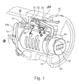
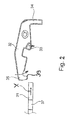
- Such a mechanical steering lock is for example from the DE102010038160 A1 known and in the FIGS. 1 and 2 shown, wherein the Fig. 1 a partially cutaway detail view of the Lenkungsverrieglung with a housing 15, a lock cylinder received therein 10 and essential elements of a later described in detail locking mechanism for a (not shown) locking bolt, and Fig. 2 represents isolated elements of the security mechanism.
- Such steering locks typically have the lock cylinder 10 with a keyway 12 into which a key (not shown) can be inserted to release the lock cylinder 10.
- a cylinder core 11 can be rotated by means of the key from an initial or closed position by defined rotational angle ranges in at least two defined successive operating positions, which are defined by perceptible locking positions.
- the first operating position is also referred to as the "ACC" position (of “accumulator”).
- the power supply of selected units of the vehicle eg blower, radio, windows, actuators for seat adjustment, etc.
- the first position is typically achieved after a defined first rotation angle range of the key and thus of the cylinder core 11 by about 60 °, the ACC contact for reasons of manufacturing tolerance and safe adjustment of the shift position already shortly before reaching the detent position will be produced.
- the ACC contact remains closed from this position beyond the next detent position.
- the voltage supply of ignition and engine consumers (eg release of fuel ) produced.
- This position is also referred to as "normal operating position” or “IGN” position (of "ignition”).
- IGN normal operating position
- the safe adjustment of the shift position is already made shortly before reaching the detent position of the second operating position and it remains from this position, if necessary, even closed to the start position of the key or cylinder core, if this is present as described below.
- this third operating position may follow, in which the starter is actuated when producing a starter contact and by a further rotation of the cylinder core 11 by means of the key by a rotation angle range of a further approximately 30 ° from the second operating position against a spring load is reached.
- the spring load returns the cylinder core 11 after releasing the key and starting the engine back to the "normal operating position".
- a separate starter button may be provided, with which the starting of the engine is triggered by producing a starter contact.
- the mechanical locking bolt (in FIG Fig. 3b shown schematically), the is movably mounted in the steering lock, from a first position (locking position) in which it in one of a plurality of recesses on the circumference of a locking ring (in Fig. 3b only one such recess is shown), which is coupled to a steering column of the vehicle, is engaged and thereby prevents their rotation, moved to a second position in which it is fully disengaged from the recess of the locking ring in a release position in which he Steering operation releases.
- the locking bolt is mechanically coupled to the cylinder core of the lock cylinder, for example via a control element 13 with a control or lifting cam 13a, which is in engagement with a driver of the locking bolt, so that a rotation about a rotational angle ⁇ of the lock cylinder or the cylinder core eleventh is transmitted to the control element 13 and the rotation of the control cam 13a via the driver generates a translational movement of the locking bolt.
- the rotation of the lock cylinder or cylinder core in the first operating position causes the translational movement of the locking bolt from the locking position to the disengaged or released position.
- the mechanical steering lock then has a securing device which is mechanically associated with both the lock cylinder and the locking bolt and has a securing element which is movably mounted in the steering lock between a deactivated position or release position and an activated position or securing position.
- the securing element In the deactivated position, the securing element has no influence on the locking bolt and its movement.
- the activated position or securing position the securing element is in mechanical engagement with the locking bolt or an extension of the same and prevents a return movement of the locking bolt in its first position or locking position, as long as the key is in the keyway.
- These mechanical securing of the locking bolt by the securing element is intended to prevent unintentional engagement of the locking bolt in a recess of the locking rim while driving.
- the in Fig. 1 and 2 when in the DE102010038160 A1 described embodiment of the securing device, the in Fig. 1 and 2 1, this comprises a sensing element 14 configured as a movable slider which is movable on the keyway 12 between a retracted position (as shown) when no key is in the keyway and an extended position by inserting the key into the keyway ,
- the securing element is designed as a pivoting lever 32 which is mounted on a guide shaft 33, whose pins are guided on both sides in elongated guides, movable and by a biasing spring 30 in the in Fig. 1 shown disabled position or release position is forced.
- the preloading spring 30 exerts a preloading on the pivoting lever 32 in such a way that, on the one hand, it extends in total in a direction B towards the locking cylinder or against a coupling element 31, which serves as a mechanical extension of the locking bolt, as well as in the direction of a rotation C (here clockwise) is biased about the pins of the guide shaft 33.
- the voltage applied by the preload in direction B on the coupling element 31 pivot lever 32 pivots about a contact line A on the coupling element and is otherwise guided on the pin of the guide shaft 33.
- the detection element 14 projecting into the keyway is displaced to the extended position and thereby engages with a hook-like end 34 of the pivot lever 32, so that the pivot lever 32 counter to the biasing force of the spring 30 in the counterclockwise direction ( against the direction C) is pivoted about the contact line A on the coupling element 31 under guidance on the guide shaft 33 from the release position to the activated position or securing position.
- the opposite hook-like end 35 of the pivot lever 32 engage with a recess 37 which is formed in the elongated coupling element 31.
- the control in the prior art has a relatively steep control cam, so that such a long stroke of the locking bolt within the limited range of rotation of the lock cylinder or the cylinder core of about 60 ° when unlocking and turning from the closed position to the first Operating position (or "ACC" position) can be achieved (the assignment between Rotation of the lock cylinder and stroke or movement distance of the locking bolt in the prior art corresponds to the curve C in Fig. 3a ; the locking position of the locking bolt is the position "U” in Fig. 3b and the disengaged position or release position of the lock pin in the prior art is the position "V").
- the steep control curve inevitably increases the torque required to turn, resulting in a reduced sense of comfort because this moment is manually applied to the mechanical steering lock via the key.
- one or more of the outer telescoping tube segments of the steering column has been longitudinally slotted so that the locking pin need not be fully withdrawn from the tube segment (s) and yet a longitudinal movement of the steering column tube segments in the longitudinal adjustment or compression in frontal impact is possible.
- the slot in the longitudinal direction but the strength of the respective pipe segment and thus the entire telescopic steering column is significantly weakened.
- the invention aims to solve at least some of these problems and it is the object of the invention to provide a generic mechanical steering lock for vehicles in proposal, whose comfort feeling when unlocking and / or their strength is improved even when used with a telescopic steering column.
- the mechanical steering lock for vehicles therefore has a lock cylinder with a key channel, in the in a closed position a key is used to release the lock cylinder, and after the release of the closed position over at least two defined successive rotation angle ranges, each leading to one of a plurality of defined operating positions, is rotatable, and a locking pin which is movably mounted in the steering lock to between a first position in which it engages in a ratchet on a steering column to prevent its rotation, and a second position in which it is disengaged from the ratchet, to be moved translationally.
- the locking bolt is mechanically coupled to the lock cylinder such that rotation of the lock cylinder causes movement of the lock bolt from the first position to the second position, this mechanical coupling being configured in accordance with the invention such that rotation of the lock cylinder is over at least two of the defined rotation angle ranges causes the movement of the locking bolt from the first position to the second position.
- the first defined rotation angle range preferably corresponds to a rotation of the lock cylinder in an "ACC" position and the second, subsequent defined rotation angle range corresponds to a rotation of the lock cylinder into an "IGN” or drive position.
- the movement distance of the locking bolt which is achieved by the mechanical coupling of lock cylinder rotation and locking bolt, for example via a lifting or control curve, unlike in the prior art to two (or more) successive defined rotational angle ranges of the lock cylinder, between them a predetermined Sch thoroughlyzylinder- or contact or operating position is distributed.
- the required to reach the driving position total stroke of the locking bolt is thus achieved only in the second (or another) of the successive operating positions of the lock cylinder, which is not necessarily must follow each other directly, but for example, can be separated by an intermediate region in which the rotation of the lock cylinder causes no translational movement of the locking bolt.
- the stroke or movement distance of the locking bolt is assigned to a larger rotation angle range of the lock cylinder, either the torque required for turning can be reduced, which increases the comfort for the user, or it can at approximately constant rotation angle range of the lock cylinder and thus without changing the defined operating positions the lock cylinder at a substantially constant moment or constant slope of the control cam, a larger total stroke can be achieved, so that the locking bolt can be pulled out even with more stable designed steering columns with larger diameter, especially in telescopic steering columns, completely out of the or the pipe segment (s) of the steering column, without that they must be provided with a movement slot for the longitudinal movement of the pipe segments as in the prior art.
- the invention utilizes a previously “unused” but always present rotational angle range of the lock cylinder (typically that of the "ACC" position to the “IGN” position) in addition to the movement of the locking bolt.
- the mechanical coupling of the locking bolt is achieved with the lock cylinder for moving the locking bolt from the first to the second position via a relative rotation of a control cam and a driver therewith engaged, of which one element rotationally fixed to the locking bolt and the other rotationally fixed to the lock cylinder is coupled.
- the control cam which is effective for the movement of the locking bolt is thereby extended beyond the first rotational angle range into the second (or a further) rotational angle range and can thus be inclined more flatly, which leads to a lower torque or cause a larger stroke at approximately the same pitch.
- the slope of the cam must It can be neither constant nor continuous over the at least two (or more) involved in the stroke rotation angle ranges, but may vary in sections.
- the steering lock has a securing mechanism with a securing element which is mechanically associated with both the lock cylinder and the locking bolt and is movably mounted in the steering lock such that it is moved from a release position into a locking position by inserting the key into the keyway, in that it is in mechanical engagement with the locking bolt when in the second position, thereby preventing the locking bolt from returning to the first position as long as the key is in the keyway.
- the mechanical assignment of securing element and locking bolt is designed so that the securing element is moved between the release position and the locking stage in an intermediate Arret istsease in which it prevents the locking bolt by a mechanical engagement on a return movement to the first position while the locking pin is in a position between the first and second positions.
- this intermediate locking step is assigned to the first of the at least two operating positions of the lock cylinder, which is reached after the first rotation angle range, while the locking step is assigned to the second of the at least two operating positions of the lock cylinder, which is reached after the second rotation angle range.
- the securing element is preferably as in the described prior art, a pivot lever which is movably mounted on a guide axis and which is pivotable via engagement with a protruding into the key channel movable detection element which is moved by the key inserted in the keyway key.
- the locking step and the intermediate locking step are in this case preferably formed by two recesses in the locking bolt or in a mechanical extension of the same, in each of which a locking or engagement step of a preferably hook-like end of the pivot lever can engage successively in the at least two positions of the locking bolt, the associated with the operating positions of the lock cylinder.
- the locking bolt or the mechanical extension of the same has a recess and the end of the pivot lever has two latching steps, which successively engage in the at least two positions of the locking bolt with the recess, which are associated with the operating positions of the lock cylinder.
- the mechanical steering lock for vehicles according to the invention is largely based on the in the FIGS. 1 and 2 shown and already in the introduction with reference to the DE102010038160 A1 described in detail steering lock. A description of the basic structural elements will therefore not be repeated here, and reference is made in this respect to the remarks in the introduction to the description.
- the steering lock according to the invention differs on the one hand in the structure of the mechanical coupling of the lock cylinder with the locking bolt, which generates its movement, as well as in the structure of the securing element for the locking bolt.
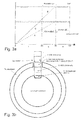
- the Fig. 3a shows a schematic representation of a settlement of a lifting or control curve of a mechanical Coupling of lock cylinder and locking bolt in the prior art and according to the invention.
- the abscissa shows the angle of rotation ⁇ of the lock cylinder and the ordinate the stroke of the control cam, which causes the movement distance X of the locking bolt.
- the curve C corresponds to the described in the introduction of the prior art, in which the entire movement path of the locking bolt is achieved by turning the lock cylinder over the rotation angle range I (from the closed position to the locked position of the operating position 1, usually the "ACC" position corresponds to - typical angle range: approx. 60 °).
- the further rotation of the lock cylinder over the further rotation angle ranges II and III causes no further lifting or retracting movement of the locking bolt.
- the locking pin is so in the prior art with reaching the detent position 1, wherein the ACC contact is made, from the locking position U, in which it is engaged with a recess of the locking ring, retracted to the fully disengaged position V (see Fig. 3b ).
- the curve A in Fig. 3a corresponds to a variant of the invention in which the entire retraction movement distance of the locking bolt at approximately the same stroke X as in the curve C, but by turning over the rotation angle ranges I and II of the lock cylinder is reached (from the closed position over the detent position 1, which usually corresponds to the "ACC" position, in the rest position 2, which usually corresponds to the "IGN” position).
- the slope of the cam is here constant or substantially constant. However, the slope can be different in several sections and each constant or completely or partially progressive or degressive.
- the curve B corresponds to a modification of the first variant of the invention, in which, although about the same slope as in the curve C is applied, the entire movement distance of the locking bolt but by turning is achieved over the rotational angle ranges I and II of the lock cylinder, so that in the locking position 2, a considerably larger stroke of the locking bolt is reached.
- the curve A corresponding variant of the invention allows a lower torque as in the prior art (which is why the application is preferred for small cars) and the curve B corresponding variant of the invention allows a greater range of movement of the locking bolt (which is why the application in heavy vehicles with larger dimensioned steering column or a telescopic steering column is preferred).
- the locking pin is in the locked position 1 of the lock cylinder, for example, at the position W and is thus already disengaged from the recess of the locking ring, so that a rotation of the steering wheel and a sliding or rolling of the vehicle is traveled is possible.
- the locking bolt is then in the fully retracted position V as in the prior art, which corresponds to the driving position.
- the locking pin is in the locked position 1 of the lock cylinder, for example, at the position V and thus is already in a position corresponding to the fully retracted position in the prior art.
- the locking position 2 of the locking bolt in this variant is still further withdrawn, for example, in the position Y, in which he is then completely bent back from the telescopic sleeve (s) even with steering columns with large diameter or telescopic steering columns, so that they do not must be provided a movement slot.
- the rotation angle ranges between the defined operating positions of the lock cylinder are exemplary and not limited to the angle specifications. It is of course preferable to maintain the rotational angle ranges of the lock cylinder according to the steering locks used in practice, so that the habits of the users do not have to be changed or not changed significantly. An enlargement of the rotation angle ranges over a total of 90 to 120 ° addition is also not advantageous because otherwise the operation of the lock cylinder by the user over all operating positions can not be reached from the wrist without grasping.
- the rotation angle ranges I and II can certainly be increased in variants that dispense with the third rotation angle range in favor of a separate start switch as described in the introduction.
- latching or operating positions of the lock cylinder and corresponding contact positions can be included in the mechanical coupling of lock cylinder and Verriegelungsbolzenhub, provided that it is ensured that the locking bolt has reached the unlocking end position in the driving position, in which he also by the securing element is secured.
- the "active" part of the control cam and thus the movement of the locking bolt does not end as usual in the prior art just before the defined locking positions but can be quite well before terminated to ensure even with larger tolerances that the locking pin safely disengaged and is secured when the respective contact is made.
- the slope of the control curve must not be linear and continuous within the respective rotation angle ranges but can follow any trajectory.
- third rotation angle range III (between the "IGN” position and a "START" position), which typically serves to start the starter or the engine and is operated only briefly, are used for the control cam and the translational movement of the locking bolt.
- the safety mechanism for the locking bolt of the mechanical steering lock in the retracted Position or driving position is preferably as described in the prior art according to the DE102010038160 A1 configured and has a securing element, which is assigned to both the lock cylinder and the locking bolt mechanically and so movably mounted in the steering lock that it is moved by inserting the key in the keyway of a release position in a locking stage in which it is in a mechanical engagement is located with the locking bolt when it is in the second position (the fully retracted position), and thereby prevents the locking bolt from moving back to the first position as long as the key is in the keyway.
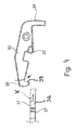
- the securing element can also be configured in the invention, for example, as a pivot lever 32 which is pivotally and additionally slidably mounted as described in the introduction about a guide axis 33 and the projecting into the keyway 12 detection element 14, which is provided with an end portion 34 of the pivot lever 32nd engages, is pivotable.
- This intermediate locking step is preferably associated with the first of the at least two locking or operating positions of the lock cylinder, which is reached after the first rotation angle range (typically the "ACC" position), while the completely retracted position of the locking bolt in driving position corresponding locking stage of the second of the at least two locking or operating positions of the lock cylinder is assigned, which is reached after the second rotation angle range (typically the "IGN” position).
- the first rotation angle range typically the "ACC” position
- IGN second rotation angle range
- the two locking stages comprise two successive recesses 37 and 38 in the locking bolt or in a mechanical extension 31 thereof, in each of which a locking or engagement stage 39 of the preferably hook-like end 35 of the pivot lever 32 successively in the retraction movement of the locking bolt in the direction X in two positions of the locking bolt can engage, which are preferably assigned to the operating positions of the lock cylinder.
- the two locking steps comprise two successive and offset detent steps 40 and 41 which are provided on the end portion 35 of the pivoting lever 32 in succession upon retraction of the locking bolt or mechanical extension 31 thereof in direction X into a recess formed therein 37 intervene.
- the inventive idea is not limited to a realization in the described steering lock but can be applied to other types of steering locks, provided that they have a mechanical coupling of the lock cylinder with the locking bolt for moving the same in response to the rotation of the lock cylinder or a cylinder core.
- the inventive idea of the plurality of locking stages is not limited to an application in the described locking mechanism with the pivot lever, but can be applied to other mechanical security mechanisms.
Landscapes
- Engineering & Computer Science (AREA)
- Mechanical Engineering (AREA)
- Lock And Its Accessories (AREA)
Applications Claiming Priority (2)
| Application Number | Priority Date | Filing Date | Title |
|---|---|---|---|
| DE102013015629 | 2013-09-19 | ||
| DE102013018835.0A DE102013018835A1 (de) | 2013-09-19 | 2013-11-08 | Mechanische Lenkungsverriegelung für Fahrzeuge |
Publications (2)
| Publication Number | Publication Date |
|---|---|
| EP2851245A1 true EP2851245A1 (fr) | 2015-03-25 |
| EP2851245B1 EP2851245B1 (fr) | 2016-06-29 |
Family
ID=51618982
Family Applications (1)
| Application Number | Title | Priority Date | Filing Date |
|---|---|---|---|
| EP14184936.4A Not-in-force EP2851245B1 (fr) | 2013-09-19 | 2014-09-16 | Verrouillage de direction mécanique pour véhicules |
Country Status (3)
| Country | Link |
|---|---|
| EP (1) | EP2851245B1 (fr) |
| CN (1) | CN104442693B (fr) |
| DE (1) | DE102013018835A1 (fr) |
Families Citing this family (2)
| Publication number | Priority date | Publication date | Assignee | Title |
|---|---|---|---|---|
| DE102016109832A1 (de) * | 2016-04-13 | 2017-10-19 | Huf Hülsbeck & Fürst Gmbh & Co. Kg | Führungsvorrichtung für die Führung eines Sperrbolzens eines Lenkradschlosses |
| DE102019125189A1 (de) * | 2019-09-19 | 2021-03-25 | Huf Hülsbeck & Fürst Gmbh & Co. Kg | Verriegelungsvorrichtung für ein funktionswesentliches Bauteil, Funktionseinheit für ein Fahrzeug sowie Verfahren zum zerstörungsfreien Abstützen einer Bewegung eines funktionswesentlichen Bauteils |
Citations (7)
| Publication number | Priority date | Publication date | Assignee | Title |
|---|---|---|---|---|
| FR2573465A1 (fr) * | 1984-11-19 | 1986-05-23 | Emain Jean | Antivol notamment pour vehicules automobiles |
| JP2002371735A (ja) * | 2001-06-15 | 2002-12-26 | Yuhshin Co Ltd | ステアリングロック装置 |
| JP2006248520A (ja) * | 2006-04-19 | 2006-09-21 | Yuhshin Co Ltd | ステアリングロック装置 |
| FR2909952A1 (fr) * | 2006-12-19 | 2008-06-20 | Valeo Securite Habitacle Sas | Antivol de vehicule comprenant un boitier equipe et procede de realisation dudit boitier. |
| DE102008014636A1 (de) * | 2007-03-27 | 2008-10-02 | U-Shin Ltd. | Lenkradschlosseinrichtung |
| EP2420416A2 (fr) * | 2010-08-19 | 2012-02-22 | Huf Hülsbeck & Fürst GmbH & Co. KG | Dispositif de logement d'un élément de blocage mobile |
| DE102010038160A1 (de) | 2010-10-13 | 2012-04-19 | Huf Hülsbeck & Fürst Gmbh & Co. Kg | Vorrichtung zur Verlagerung eines Sperrelementes |
Family Cites Families (2)
| Publication number | Priority date | Publication date | Assignee | Title |
|---|---|---|---|---|
| FR2737453B1 (fr) * | 1995-08-01 | 1997-08-29 | Antivols Simplex Sa | Agencement d'un antivol de colonne de direction |
| JP4073884B2 (ja) * | 2004-03-26 | 2008-04-09 | 株式会社ホンダロック | 車両用操作ノブ付きステアリングロック装置 |
-
2013
- 2013-11-08 DE DE102013018835.0A patent/DE102013018835A1/de not_active Withdrawn
-
2014
- 2014-09-16 EP EP14184936.4A patent/EP2851245B1/fr not_active Not-in-force
- 2014-09-19 CN CN201410484102.5A patent/CN104442693B/zh not_active Expired - Fee Related
Patent Citations (7)
| Publication number | Priority date | Publication date | Assignee | Title |
|---|---|---|---|---|
| FR2573465A1 (fr) * | 1984-11-19 | 1986-05-23 | Emain Jean | Antivol notamment pour vehicules automobiles |
| JP2002371735A (ja) * | 2001-06-15 | 2002-12-26 | Yuhshin Co Ltd | ステアリングロック装置 |
| JP2006248520A (ja) * | 2006-04-19 | 2006-09-21 | Yuhshin Co Ltd | ステアリングロック装置 |
| FR2909952A1 (fr) * | 2006-12-19 | 2008-06-20 | Valeo Securite Habitacle Sas | Antivol de vehicule comprenant un boitier equipe et procede de realisation dudit boitier. |
| DE102008014636A1 (de) * | 2007-03-27 | 2008-10-02 | U-Shin Ltd. | Lenkradschlosseinrichtung |
| EP2420416A2 (fr) * | 2010-08-19 | 2012-02-22 | Huf Hülsbeck & Fürst GmbH & Co. KG | Dispositif de logement d'un élément de blocage mobile |
| DE102010038160A1 (de) | 2010-10-13 | 2012-04-19 | Huf Hülsbeck & Fürst Gmbh & Co. Kg | Vorrichtung zur Verlagerung eines Sperrelementes |
Also Published As
| Publication number | Publication date |
|---|---|
| CN104442693B (zh) | 2017-04-12 |
| EP2851245B1 (fr) | 2016-06-29 |
| DE102013018835A1 (de) | 2015-03-19 |
| CN104442693A (zh) | 2015-03-25 |
Similar Documents
| Publication | Publication Date | Title |
|---|---|---|
| EP3870786B1 (fr) | Serrure conçue pour un véhicule automobile, en particulier serrure de véhicule automobile à actionnement électrique | |
| EP3218246B1 (fr) | Colonne de direction comportant une butée longitudinale présentant une fonction de libération en cas d'accident | |
| DE19752519A1 (de) | Verriegelungseinrichtung für Lenkungen von Kraftfahrzeugen | |
| DE3827418C2 (fr) | ||
| DE102010018243B4 (de) | Schließzylinderanordnung | |
| DE102015108664A1 (de) | Schließzylinder mit Rückstellsperre | |
| EP2300280A2 (fr) | Procédé servant à commander le système de direction d'une moto | |
| DE2441463B2 (de) | Zylinderschloss mit einem axial verschiebbaren zylinderkern, insbesondere fuer ein lenkschloss in kraftfahrzeugen | |
| EP2851245B1 (fr) | Verrouillage de direction mécanique pour véhicules | |
| EP1057696B1 (fr) | Dispositif à arceau de sécurité pour véhicules | |
| EP1431482A2 (fr) | Serrure de porte pour véhicule automobile | |
| DE102017115276A1 (de) | Verriegelungsvorrichtung sowie Lenksäulenbaugruppe | |
| DE3236190C2 (de) | Lenk- und Zündschloß für Kraftfahrzeuge | |
| EP1121278B1 (fr) | Dispositif de commande pour l'allumage et le blocage de la direction d'une automobile | |
| EP2244925B1 (fr) | Colonne de direction réglable pour une automobile | |
| DE102022111137B4 (de) | Betätigungsvorrichtung zum öffnen und schliessen einer abdeckung in oder an einem fahrzeug | |
| WO2019233523A1 (fr) | Serrure de véhicule à moteur, à commande électrique | |
| DE19838992A1 (de) | Zündanlaßschalter für Kraftfahrzeuge mit elektronischer Lenkungsverriegelung | |
| DE102013018836A1 (de) | Mechanische Sperrvorrichtung, insbesondere für den Fahrzeugbereich | |
| DE2621857C3 (de) | Lenk- und Zündschloß | |
| DE102015105221B4 (de) | Überrollschutzsystem für Kraftfahrzeuge | |
| DE3534523C2 (de) | Lenkradschloß | |
| EP1387783B1 (fr) | Demarreur a commande manuelle pour unite sans cle servant au controle d'autorisation de demarrage de moteur d'un vehicule automobile | |
| DE102016123331A1 (de) | Verbesserte Verriegelungsvorrichtung | |
| DE2605589B2 (de) | Kraftfahrzeug-Lenkschloß |
Legal Events
| Date | Code | Title | Description |
|---|---|---|---|
| PUAI | Public reference made under article 153(3) epc to a published international application that has entered the european phase |
Free format text: ORIGINAL CODE: 0009012 |
|
| 17P | Request for examination filed |
Effective date: 20140916 |
|
| AK | Designated contracting states |
Kind code of ref document: A1 Designated state(s): AL AT BE BG CH CY CZ DE DK EE ES FI FR GB GR HR HU IE IS IT LI LT LU LV MC MK MT NL NO PL PT RO RS SE SI SK SM TR |
|
| AX | Request for extension of the european patent |
Extension state: BA ME |
|
| R17P | Request for examination filed (corrected) |
Effective date: 20150513 |
|
| RBV | Designated contracting states (corrected) |
Designated state(s): AL AT BE BG CH CY CZ DE DK EE ES FI FR GB GR HR HU IE IS IT LI LT LU LV MC MK MT NL NO PL PT RO RS SE SI SK SM TR |
|
| GRAP | Despatch of communication of intention to grant a patent |
Free format text: ORIGINAL CODE: EPIDOSNIGR1 |
|
| INTG | Intention to grant announced |
Effective date: 20160112 |
|
| GRAS | Grant fee paid |
Free format text: ORIGINAL CODE: EPIDOSNIGR3 |
|
| GRAA | (expected) grant |
Free format text: ORIGINAL CODE: 0009210 |
|
| AK | Designated contracting states |
Kind code of ref document: B1 Designated state(s): AL AT BE BG CH CY CZ DE DK EE ES FI FR GB GR HR HU IE IS IT LI LT LU LV MC MK MT NL NO PL PT RO RS SE SI SK SM TR |
|
| REG | Reference to a national code |
Ref country code: GB Ref legal event code: FG4D Free format text: NOT ENGLISH |
|
| REG | Reference to a national code |
Ref country code: CH Ref legal event code: EP |
|
| REG | Reference to a national code |
Ref country code: AT Ref legal event code: REF Ref document number: 808830 Country of ref document: AT Kind code of ref document: T Effective date: 20160715 |
|
| REG | Reference to a national code |
Ref country code: IE Ref legal event code: FG4D Free format text: LANGUAGE OF EP DOCUMENT: GERMAN |
|
| REG | Reference to a national code |
Ref country code: DE Ref legal event code: R096 Ref document number: 502014001009 Country of ref document: DE |
|
| REG | Reference to a national code |
Ref country code: FR Ref legal event code: PLFP Year of fee payment: 3 |
|
| REG | Reference to a national code |
Ref country code: LT Ref legal event code: MG4D |
|
| PG25 | Lapsed in a contracting state [announced via postgrant information from national office to epo] |
Ref country code: FI Free format text: LAPSE BECAUSE OF FAILURE TO SUBMIT A TRANSLATION OF THE DESCRIPTION OR TO PAY THE FEE WITHIN THE PRESCRIBED TIME-LIMIT Effective date: 20160629 Ref country code: NO Free format text: LAPSE BECAUSE OF FAILURE TO SUBMIT A TRANSLATION OF THE DESCRIPTION OR TO PAY THE FEE WITHIN THE PRESCRIBED TIME-LIMIT Effective date: 20160929 Ref country code: LT Free format text: LAPSE BECAUSE OF FAILURE TO SUBMIT A TRANSLATION OF THE DESCRIPTION OR TO PAY THE FEE WITHIN THE PRESCRIBED TIME-LIMIT Effective date: 20160629 |
|
| REG | Reference to a national code |
Ref country code: NL Ref legal event code: MP Effective date: 20160629 |
|
| PG25 | Lapsed in a contracting state [announced via postgrant information from national office to epo] |
Ref country code: HR Free format text: LAPSE BECAUSE OF FAILURE TO SUBMIT A TRANSLATION OF THE DESCRIPTION OR TO PAY THE FEE WITHIN THE PRESCRIBED TIME-LIMIT Effective date: 20160629 Ref country code: RS Free format text: LAPSE BECAUSE OF FAILURE TO SUBMIT A TRANSLATION OF THE DESCRIPTION OR TO PAY THE FEE WITHIN THE PRESCRIBED TIME-LIMIT Effective date: 20160629 Ref country code: SE Free format text: LAPSE BECAUSE OF FAILURE TO SUBMIT A TRANSLATION OF THE DESCRIPTION OR TO PAY THE FEE WITHIN THE PRESCRIBED TIME-LIMIT Effective date: 20160629 Ref country code: LV Free format text: LAPSE BECAUSE OF FAILURE TO SUBMIT A TRANSLATION OF THE DESCRIPTION OR TO PAY THE FEE WITHIN THE PRESCRIBED TIME-LIMIT Effective date: 20160629 Ref country code: GR Free format text: LAPSE BECAUSE OF FAILURE TO SUBMIT A TRANSLATION OF THE DESCRIPTION OR TO PAY THE FEE WITHIN THE PRESCRIBED TIME-LIMIT Effective date: 20160930 Ref country code: NL Free format text: LAPSE BECAUSE OF FAILURE TO SUBMIT A TRANSLATION OF THE DESCRIPTION OR TO PAY THE FEE WITHIN THE PRESCRIBED TIME-LIMIT Effective date: 20160629 |
|
| PG25 | Lapsed in a contracting state [announced via postgrant information from national office to epo] |
Ref country code: IT Free format text: LAPSE BECAUSE OF FAILURE TO SUBMIT A TRANSLATION OF THE DESCRIPTION OR TO PAY THE FEE WITHIN THE PRESCRIBED TIME-LIMIT Effective date: 20160629 Ref country code: SK Free format text: LAPSE BECAUSE OF FAILURE TO SUBMIT A TRANSLATION OF THE DESCRIPTION OR TO PAY THE FEE WITHIN THE PRESCRIBED TIME-LIMIT Effective date: 20160629 Ref country code: EE Free format text: LAPSE BECAUSE OF FAILURE TO SUBMIT A TRANSLATION OF THE DESCRIPTION OR TO PAY THE FEE WITHIN THE PRESCRIBED TIME-LIMIT Effective date: 20160629 Ref country code: RO Free format text: LAPSE BECAUSE OF FAILURE TO SUBMIT A TRANSLATION OF THE DESCRIPTION OR TO PAY THE FEE WITHIN THE PRESCRIBED TIME-LIMIT Effective date: 20160629 Ref country code: IS Free format text: LAPSE BECAUSE OF FAILURE TO SUBMIT A TRANSLATION OF THE DESCRIPTION OR TO PAY THE FEE WITHIN THE PRESCRIBED TIME-LIMIT Effective date: 20161029 Ref country code: CZ Free format text: LAPSE BECAUSE OF FAILURE TO SUBMIT A TRANSLATION OF THE DESCRIPTION OR TO PAY THE FEE WITHIN THE PRESCRIBED TIME-LIMIT Effective date: 20160629 |
|
| PG25 | Lapsed in a contracting state [announced via postgrant information from national office to epo] |
Ref country code: ES Free format text: LAPSE BECAUSE OF FAILURE TO SUBMIT A TRANSLATION OF THE DESCRIPTION OR TO PAY THE FEE WITHIN THE PRESCRIBED TIME-LIMIT Effective date: 20160629 Ref country code: BE Free format text: LAPSE BECAUSE OF NON-PAYMENT OF DUE FEES Effective date: 20160930 Ref country code: PL Free format text: LAPSE BECAUSE OF FAILURE TO SUBMIT A TRANSLATION OF THE DESCRIPTION OR TO PAY THE FEE WITHIN THE PRESCRIBED TIME-LIMIT Effective date: 20160629 Ref country code: SM Free format text: LAPSE BECAUSE OF FAILURE TO SUBMIT A TRANSLATION OF THE DESCRIPTION OR TO PAY THE FEE WITHIN THE PRESCRIBED TIME-LIMIT Effective date: 20160629 Ref country code: PT Free format text: LAPSE BECAUSE OF FAILURE TO SUBMIT A TRANSLATION OF THE DESCRIPTION OR TO PAY THE FEE WITHIN THE PRESCRIBED TIME-LIMIT Effective date: 20161031 |
|
| REG | Reference to a national code |
Ref country code: DE Ref legal event code: R097 Ref document number: 502014001009 Country of ref document: DE |
|
| PG25 | Lapsed in a contracting state [announced via postgrant information from national office to epo] |
Ref country code: MC Free format text: LAPSE BECAUSE OF FAILURE TO SUBMIT A TRANSLATION OF THE DESCRIPTION OR TO PAY THE FEE WITHIN THE PRESCRIBED TIME-LIMIT Effective date: 20160629 |
|
| PG25 | Lapsed in a contracting state [announced via postgrant information from national office to epo] |
Ref country code: DK Free format text: LAPSE BECAUSE OF FAILURE TO SUBMIT A TRANSLATION OF THE DESCRIPTION OR TO PAY THE FEE WITHIN THE PRESCRIBED TIME-LIMIT Effective date: 20160629 |
|
| 26N | No opposition filed |
Effective date: 20170330 |
|
| PLBE | No opposition filed within time limit |
Free format text: ORIGINAL CODE: 0009261 |
|
| STAA | Information on the status of an ep patent application or granted ep patent |
Free format text: STATUS: NO OPPOSITION FILED WITHIN TIME LIMIT |
|
| REG | Reference to a national code |
Ref country code: IE Ref legal event code: MM4A |
|
| PG25 | Lapsed in a contracting state [announced via postgrant information from national office to epo] |
Ref country code: IE Free format text: LAPSE BECAUSE OF NON-PAYMENT OF DUE FEES Effective date: 20160916 |
|
| PG25 | Lapsed in a contracting state [announced via postgrant information from national office to epo] |
Ref country code: SI Free format text: LAPSE BECAUSE OF FAILURE TO SUBMIT A TRANSLATION OF THE DESCRIPTION OR TO PAY THE FEE WITHIN THE PRESCRIBED TIME-LIMIT Effective date: 20160629 Ref country code: LU Free format text: LAPSE BECAUSE OF NON-PAYMENT OF DUE FEES Effective date: 20160916 Ref country code: BG Free format text: LAPSE BECAUSE OF FAILURE TO SUBMIT A TRANSLATION OF THE DESCRIPTION OR TO PAY THE FEE WITHIN THE PRESCRIBED TIME-LIMIT Effective date: 20160929 |
|
| REG | Reference to a national code |
Ref country code: FR Ref legal event code: PLFP Year of fee payment: 4 |
|
| REG | Reference to a national code |
Ref country code: BE Ref legal event code: MM Effective date: 20160930 |
|
| REG | Reference to a national code |
Ref country code: CH Ref legal event code: PL |
|
| PG25 | Lapsed in a contracting state [announced via postgrant information from national office to epo] |
Ref country code: HU Free format text: LAPSE BECAUSE OF FAILURE TO SUBMIT A TRANSLATION OF THE DESCRIPTION OR TO PAY THE FEE WITHIN THE PRESCRIBED TIME-LIMIT; INVALID AB INITIO Effective date: 20140916 |
|
| PG25 | Lapsed in a contracting state [announced via postgrant information from national office to epo] |
Ref country code: MT Free format text: LAPSE BECAUSE OF FAILURE TO SUBMIT A TRANSLATION OF THE DESCRIPTION OR TO PAY THE FEE WITHIN THE PRESCRIBED TIME-LIMIT Effective date: 20160629 Ref country code: CY Free format text: LAPSE BECAUSE OF FAILURE TO SUBMIT A TRANSLATION OF THE DESCRIPTION OR TO PAY THE FEE WITHIN THE PRESCRIBED TIME-LIMIT Effective date: 20160629 Ref country code: MK Free format text: LAPSE BECAUSE OF FAILURE TO SUBMIT A TRANSLATION OF THE DESCRIPTION OR TO PAY THE FEE WITHIN THE PRESCRIBED TIME-LIMIT Effective date: 20160629 |
|
| PG25 | Lapsed in a contracting state [announced via postgrant information from national office to epo] |
Ref country code: CH Free format text: LAPSE BECAUSE OF NON-PAYMENT OF DUE FEES Effective date: 20170930 Ref country code: LI Free format text: LAPSE BECAUSE OF NON-PAYMENT OF DUE FEES Effective date: 20170930 |
|
| REG | Reference to a national code |
Ref country code: FR Ref legal event code: PLFP Year of fee payment: 5 |
|
| PG25 | Lapsed in a contracting state [announced via postgrant information from national office to epo] |
Ref country code: TR Free format text: LAPSE BECAUSE OF FAILURE TO SUBMIT A TRANSLATION OF THE DESCRIPTION OR TO PAY THE FEE WITHIN THE PRESCRIBED TIME-LIMIT Effective date: 20160629 Ref country code: AL Free format text: LAPSE BECAUSE OF FAILURE TO SUBMIT A TRANSLATION OF THE DESCRIPTION OR TO PAY THE FEE WITHIN THE PRESCRIBED TIME-LIMIT Effective date: 20160629 |
|
| GBPC | Gb: european patent ceased through non-payment of renewal fee |
Effective date: 20180916 |
|
| PG25 | Lapsed in a contracting state [announced via postgrant information from national office to epo] |
Ref country code: GB Free format text: LAPSE BECAUSE OF NON-PAYMENT OF DUE FEES Effective date: 20180916 |
|
| PGFP | Annual fee paid to national office [announced via postgrant information from national office to epo] |
Ref country code: FR Payment date: 20190923 Year of fee payment: 6 |
|
| REG | Reference to a national code |
Ref country code: AT Ref legal event code: MM01 Ref document number: 808830 Country of ref document: AT Kind code of ref document: T Effective date: 20190916 |
|
| PG25 | Lapsed in a contracting state [announced via postgrant information from national office to epo] |
Ref country code: AT Free format text: LAPSE BECAUSE OF NON-PAYMENT OF DUE FEES Effective date: 20190916 |
|
| PG25 | Lapsed in a contracting state [announced via postgrant information from national office to epo] |
Ref country code: FR Free format text: LAPSE BECAUSE OF NON-PAYMENT OF DUE FEES Effective date: 20200930 |
|
| PGFP | Annual fee paid to national office [announced via postgrant information from national office to epo] |
Ref country code: DE Payment date: 20210921 Year of fee payment: 8 |
|
| REG | Reference to a national code |
Ref country code: DE Ref legal event code: R119 Ref document number: 502014001009 Country of ref document: DE |
|
| PG25 | Lapsed in a contracting state [announced via postgrant information from national office to epo] |
Ref country code: DE Free format text: LAPSE BECAUSE OF NON-PAYMENT OF DUE FEES Effective date: 20230401 |