EP2851491A2 - Installation de verrouillage - Google Patents
Installation de verrouillage Download PDFInfo
- Publication number
- EP2851491A2 EP2851491A2 EP14185694.8A EP14185694A EP2851491A2 EP 2851491 A2 EP2851491 A2 EP 2851491A2 EP 14185694 A EP14185694 A EP 14185694A EP 2851491 A2 EP2851491 A2 EP 2851491A2
- Authority
- EP
- European Patent Office
- Prior art keywords
- pin
- cylinder
- adjusting ring
- key
- lock
- Prior art date
- Legal status (The legal status is an assumption and is not a legal conclusion. Google has not performed a legal analysis and makes no representation as to the accuracy of the status listed.)
- Granted
Links
Images


Classifications
-
- E—FIXED CONSTRUCTIONS
- E05—LOCKS; KEYS; WINDOW OR DOOR FITTINGS; SAFES
- E05B—LOCKS; ACCESSORIES THEREFOR; HANDCUFFS
- E05B27/00—Cylinder locks or other locks with tumbler pins or balls that are set by pushing the key in
- E05B27/005—Cylinder locks or other locks with tumbler pins or balls that are set by pushing the key in with changeable combinations
-
- E—FIXED CONSTRUCTIONS
- E05—LOCKS; KEYS; WINDOW OR DOOR FITTINGS; SAFES
- E05B—LOCKS; ACCESSORIES THEREFOR; HANDCUFFS
- E05B27/00—Cylinder locks or other locks with tumbler pins or balls that are set by pushing the key in
- E05B27/0053—Cylinder locks or other locks with tumbler pins or balls that are set by pushing the key in for use with more than one key, e.g. master-secondary key
-
- E—FIXED CONSTRUCTIONS
- E05—LOCKS; KEYS; WINDOW OR DOOR FITTINGS; SAFES
- E05B—LOCKS; ACCESSORIES THEREFOR; HANDCUFFS
- E05B27/00—Cylinder locks or other locks with tumbler pins or balls that are set by pushing the key in
- E05B27/0003—Details
- E05B27/0007—Rotors
- E05B27/001—Rotors having relatively movable parts, e.g. coaxial- or split-plugs
Definitions
- the invention relates to a system comprising a cylinder lock and at least three keys, wherein a first key locks the cylinder lock and is arranged to assign a first lock authorization and at least one second lock authorization in the cylinder lock, a second key locks the cylinder lock and can not issue a lock authorization, and a third key locks the cylinder lock when the first lock privilege is granted and does not lock when the second lock privilege is granted.
- a long-standing task of safety technology is to provide systems of cylinder locks and associated keys, in which on the one hand keys are provided which lock the lock anyway, while on the other hand keys are provided which lock the lock only in the presence of an authorization.
- keys should always be able to lock, others should be able to operate only the lock, and lock other keys only in certain cases, but not in others.
- the object of the invention is to provide a cylinder lock, in which the authorization for locking can be assigned in a simple, mechanical way.
- This object is achieved in that in a system shown at the outset of a cylinder lock and at least three keys, the award of the blocking privileges in the cylinder lock on mechanical way by the first key itself.
- the first key not only serves to lock the lock, but sets depending on its position when deducting by pressing a locking element a first or a second locking authorization.
- a movable blocking element can be provided which is reversibly movable by the first key from a first position corresponding to the first blocking authorization to a second position corresponding to the second blocking authorization.
- the blocking element can in particular be designed as a setting ring which switches over between a first housing pin arrangement and a second housing pin arrangement, wherein the third key can block only one of these two housing pin arrangements.
- the cylinder lock is in communication with a trap and a fourth key is provided which can not assign authorizations, the cylinder lock does not lock, but can operate the case.
- Key A can always lock the lock and assign the lock authorizations
- Key B can always lock the lock and not grant lock privileges
- Key C can only lock the lock in a single lock privilege
- Key D can never lock the lock, but only operate the latch.
- the invention may further be provided that means are provided which allow removal of the first key (key A) only in the first or second position, and prevent removal of the other key in a position which is not equal to the Ansteckposition. This ensures that only the key A granting the authorization can change the position of the lock element.
- a first housing pin assembly and a second Gehausehatan angel are provided, wherein the cylinder lock is executed in the first position for interrogating the first housing pin assembly, and in the second position for interrogating the second housing pin assembly.
- the invention further extends to a cylinder lock for such a system according to the invention, comprising a cylinder housing and a cylinder core rotatably mounted therein, wherein in the cylinder core core pin holes with core pins and housing housing bores are provided with housing pins in the cylinder housing.
- a first housing pin assembly and at least one second Gehausejanan angel is provided, which are preferably arranged offset to each other at an angle.
- a first defined cylinder core position and a second defined cylinder core position is provided, wherein the core pins cooperate in a first cylinder core position with the first housing pin assembly and cooperate in a second cylinder core position with the second housing pin assembly.
- the first housing pin assembly includes a first blocking pin and the second housing pin assembly includes a second blocking pin.
- the core pins comprise an actuating pin, which cooperates in the first cylinder core position with the first locking pin and in the second cylinder core position the second locking pin.
- a rotatably arranged adjusting ring is provided, which has an adjusting ring opening at its periphery, wherein the adjusting ring between a first adjusting ring position for interrogating the first blocking pin in the first cylinder core position and a second adjusting ring position for interrogating the second blocking pin in the second cylinder core position is movable back and forth.
- the blocking pins are designed or arranged such that the first blocking pin can penetrate into the cylinder core in the first adjusting ring position and block it, and the second blocking pin in the second setting ring position can not penetrate into the cylinder core and block it.
- keys may be provided which do not lock the cylinder lock in the first setting position while locking the cylinder lock in the second setting position.
- the first blocking pin is centered relative to the setting pin in the first cylinder core position, and the second blocking pin is offset relative to the setting pin in the second cylinder core position.
- the second blocking pin remains hanging at the interface between the adjusting ring and the cylinder core and can not penetrate into the cylinder core.
- it can also be provided to carry out the adjusting ring opening of the adjusting ring as a slot in order to enable both the first blocking pin and the second blocking pin offset thereto to be able to penetrate the setting ring opening.
- the first blocking pin has a diameter which is smaller than the diameter of the adjusting ring opening
- the second blocking pin has a diameter which is greater than the diameter of the adjusting ring opening.
- the second blocking pin at least in sections has an extension which extends over the diameter of the adjusting ring opening, so that it can not penetrate into the cylinder core.
- the second blocking pin has a base whose diameter is greater than the diameter of the adjusting ring opening, and has a nose whose diameter is smaller than the diameter of the adjusting ring opening, wherein the extent of the nose is less than or equal to the thickness of the adjusting ring is in the range of the adjusting ring opening.
- a control groove is provided on the inner circumference of the adjusting ring. This makes it possible to provide a further division level, which is located at the bottom of this control groove.
- the control groove can extend over any desired angular range, preferably over an angular range of 90 ° to 270 °, particularly preferably 180 °.
- the cylinder core can be rotated over the angular range of the control groove, but not further.
- the case of the lock can be actuated, but not a closing operation can be performed.
- the correspondingly executed key is thus suitable in any case only for actuating the case.
- the invention further extends to a flat key for a cylinder lock according to the invention, wherein the key has a milling, which is designed for engagement in the adjusting pin.
- the depth of this milling can be preferably carried out such that the adjusting pin is pressed either to the outer periphery of the adjusting ring, to the inner circumference of the adjusting ring, to the bottom of an optionally provided control groove, or not to the inner periphery of the adjusting ring.
- the invention further extends to a system of a cylinder lock according to the invention and at least one such flat key.
- a first flat key (key A) may be provided, the milling is carried out such that the adjusting pin is pressed against the outer circumference of the adjusting ring; and a second flat key (key B) may be provided, the milling of which is carried out such that the adjusting pin is pressed against the inner circumference of the adjusting ring; and a third flat key (key C) be provided, the milling is carried out such that the adjusting pin is not pressed up to the adjusting ring, but remains in the cylinder core.
- a fourth flat key (key D) may be provided in the system, the milling is carried out such that the adjusting pin is pressed against the groove bottom of the control groove.
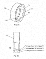
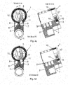
- Fig. 1 1 shows a cylinder housing 2 and a cylinder core 3 inserted therein.
- housing pin holes 5 are provided, which are filled with housing pins (not shown).
- the different core pins and housing pins ensure that only when inserting the correct key results in a dividing plane in which the cylinder core 3 can be rotated in the cylinder housing 2.
- a collar 10 is further provided, which is arranged between the cylinder core 3 and the cylinder housing 2
- the cylinder housing on a stepped edge, which allows the attachment of the adjusting ring 10.
- the adjusting ring 10 has at its periphery a collar opening 11 and at its inner periphery two exemptions 14th
- adjusting ring opening 11 of the adjusting ring 10 is designed such that it can alternatively be brought into coincidence with one of the housing pin bores 5.
- first blocking pin 8 and the second blocking pin 9 are shown, which are mounted in corresponding bores of the cylinder housing under spring tension.
- the adjusting pin 17 is further arranged, which is depending on the position of the adjusting ring 10 and the cylinder core 3 either with the first locking pin 8 or the second locking pin 9 is engaged.
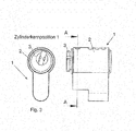
- Fig. 2a and Fig. 2b show schematic views of the adjusting ring 10.
- This has a collar opening 11, which is designed in the present embodiment as a slot.
- the exemptions 14 are provided on the inner circumference.
- the control groove has a depth of preferably about 0.3 mm and extends on the inner circumference of the adjusting ring 10 over an angular range of about 180 °.
- the adjusting ring 10 forms, in cooperation with the cylinder core 3 and the housing and core pins, three graduation planes for moving the cylinder core:
- the first graduation plane for key A forms on the outer circumference of the adjusting ring 10.
- the second graduation plane for key D forms on the groove bottom of the control groove 12.
- no dividing plane is provided, since in this key the adjusting pin 17 remains in the cylinder core.
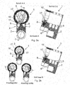
- Fig. 3 as well as the following Fig. 3a - 3d show schematic representations and sections of a cylinder lock 1 according to the invention, wherein the cylinder core 3 and the adjusting ring 10 is relative to the cylinder housing 2 in a defined position (cylinder core position 1). It is in the Fig. 3a - 3d each different keys inserted into the cylinder lock, which move the setting pin 17 to different positions. However, the keys are not shown for the sake of clarity.
- Fig. 3a - Fig. 3d each show on the left side a section along the line AA in Fig. 3 , and on the right side a section along the offset line CC as shown in Fig. 3a is indicated.
- the cylinder lock 1 comprises the cylinder housing 2 and the cylinder core 3.
- key A is inserted into the core, and pushes the adjusting pin 17 in the cylinder core 3 to its outermost position.
- the first dividing plane forms on the outer periphery of the adjusting ring 10, since the adjusting ring opening 11 is closed by the adjusting pin 17.
- the cylinder core 3 rotates and takes over the adjusting pin 17 with the adjusting ring 10
- a first housing pin assembly 6 and a second housing pin assembly 7 is provided which are mutually offset at an angle.
- a first blocking pin 8 In the first housing pin assembly 6 is a first blocking pin 8
- a second blocking pin 9 In the situation according to Fig. 3a However, these two blocking pins are ineffective because the adjusting pin 17 is brought into the 1st division level.
- the key A used may lock the cylinder lock and switch between housing pin assembly 6 and housing pin assembly 7.
- Key A assigns the blocking authorization by moving the adjusting ring and can be deducted in both positions.
- Fig. 3b shows the situation when key D is inserted into the cylinder lock 1
- key D pushes the setting pin 17 up to the groove bottom of the control groove 12, so it is the second division level achieved.
- the first blocking pin 8 protrudes into the adjusting ring opening 11 and blocks their movement.
- the adjusting ring can not move with the cylinder core 3, and the adjusting pin 17 remains in rotation of the cylinder core 3 in that position in which the control groove 12 ends.
- Fig. 3b indicated schematically below as a stop left or stop right.
- the cylinder core 3 can be moved by key D only in a certain angular range determined by the control groove and, for example, actuate the latch of the lock.
- key D can not lock the cylinder lock.
- Fig. 3c shows the situation when key B is inserted into the cylinder lock 1.
- This key should always lock.
- Key B pushes the adjusting pin 17 up to the inner circumference of the adjusting ring 10, so it is reached the 3rd division level.
- the first blocking pin 8 protrudes into the adjusting ring opening 11 and blocks their movement.
- the collar can not move with the cylinder core 3.
- the adjusting pin 17 does not hang upon rotation of the cylinder core 3, but the cylinder core 3 is freely rotatable.
- key B - like key A - can lock the cylinder lock, but does not grant a lock authorization, since the position of the adjusting ring remains unchanged.
- FIG. 3d shows the situation when key C is inserted into the cylinder lock 1.
- Key D does not push the adjusting pin 17 to the inner periphery of the adjusting ring 10, but the adjusting pin 17 remains inside the core. So none of the graduation levels is reached.
- the first blocking pin 8 remains hanging in the cylinder core 3 and prevents any movement of the cylinder core. Thus, key C can not lock the cylinder lock in this position of the adjusting ring.
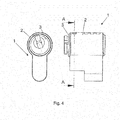
- Fig. 4 as well as the following Fig. 4a - 4d show schematic representations and sections of a cylinder lock 1 according to the invention, wherein the cylinder core 3 and the adjusting ring 10 is relative to the cylinder housing 2 in the second defined position (cylinder core position 2). It is in the Fig. 4a - 4d each different keys inserted into the cylinder lock, which move the setting pin 17 to different positions. However, the keys are not shown for the sake of clarity.
- Fig. 4a - Fig. 4d each show on the left side a section along the line AA in Fig. 4 , and on the right side a section along the offset line CC as shown in Fig. 4a is indicated.
- the cylinder lock 1 comprises the cylinder housing 2 and the cylinder core 3. It is inserted key A into the core, which pushes the adjusting pin 17 in the cylinder core 3 to its outermost position. As a result, the first dividing plane forms on the outer circumference of the adjusting ring 10, since the adjusting ring opening 11 is closed by the adjusting pin 17. Upon actuation of the key A, the cylinder core 3 rotates and takes over the adjusting pin 17 with the adjusting pin 10.
- a first housing pin assembly 6 and a second housing pin assembly 7 is provided which are mutually offset at an angle.
- a first blocking pin 8 In the first housing pin assembly 6 is a first blocking pin 8
- a second blocking pin 9 is provided in the second housing pin assembly 7, a second blocking pin 9 is provided.
- these two blocking pins are ineffective because the adjusting pin 17 is brought into the 1st division level. The key A used can thus lock the cylinder lock and switch between housing pin assembly 6 and housing pin assembly 7.
- a section along the offset line CC by the second blocking pin 9 and the adjusting pin 17 is shown.
- the second blocking pin 9 is arranged in a line with the adjusting pin 17, but offset in the normal direction to this.
- the offset is about 0.5mm.
- Fig. 4b shows the situation when key D is inserted into the cylinder lock 1.
- the key pushes the adjusting pin 17 to the groove bottom of the control groove 12, so it is the second division level achieved.
- the second blocking pin 9 protrudes into the adjusting ring opening 11 and blocks their movement.
- the adjusting ring 10 can not move with the Zylinderkem 3, and the adjusting pin 17 remains in rotation of the cylinder core 3 in that position in which the control groove 12 ends.
- the cylinder core 3 can be moved by key D only in a certain angular range determined by the control groove and, for example, actuate the latch of the lock.
- key D can not lock the cylinder lock.
- Fig. 4c shows the situation when key B is inserted into the cylinder lock 1.
- key B pushes the setting pin 17 up to the inner circumference of the adjusting ring 10, so it is reached the 3rd division level.
- the second blocking pin 9 protrudes into the adjusting ring opening 11 and blocks their movement.
- the collar can not move with the cylinder core 3.
- the adjusting pin 17 does not hang upon rotation of the cylinder core 3, but the cylinder core 3 is freely rotatable.
- key B like key A, can also lock the cylinder lock, but does not grant a lock authorization.
- FIG. 4d shows the situation when key C is inserted into the cylinder lock 1.
- Key C does not push the adjusting pin 17 to the inner circumference of the adjusting ring 10, so it is not reached the division planes.
- Between adjusting pin 17 and second locking pin 9 remains a gap.
- the second blocking pin 9 does not penetrate into the cylinder core 3, but remains hanging at the transition between the cylinder core 3 and adjusting ring opening 11, since the second blocking pin 9 is arranged offset relative to the adjusting pin 17.
- key A and B always locks, key D can only operate the case, and key C does not lock in the cylinder core position 1, but locks in the cylinder core 2 position.
- key A is able to rotate the collar 10 and thus produce the cylinder core position 1 or 2 cylinder core position.
- key A thus has the function of granting authorizations: If he brings the cylinder core and the adjusting ring into the cylinder core position 1, key C can not lock the cylinder lock. If he brings the cylinder core and the adjusting ring into the cylinder core position 2, key C can lock the cylinder lock.
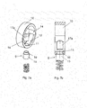
- Fig. 5 shows three-dimensional representations of a flat key 18 which is inserted into a cylinder lock according to the invention with a collar 10.
- a milling 19 is provided, the depth of which determines how far the setting pin 17 is moved.
- the adjusting ring 10 has an adjusting ring opening 11, which is designed as a slot, so that both the first blocking pin 8, as well as the staggered arranged second blocking pin 9 can be added.
- the offset is about 0.5mm along the direction of the keyway.
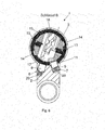
- Fig. 6 shows a further sectional view through a cylinder lock according to the invention 1.
- a cylinder core 3 is rotatably arranged in a cylinder housing 2.
- Key B is inserted into the cylinder core 3 and moves the adjusting pin 17 to the inner circumference of the adjusting ring 10.
- first housing pin assemblies 6 and second housing pin assemblies 7 are provided which comprise a first blocking pin 8 and a second blocking pin 9, which springs 20 be kept under tension.
- the key B was used, and the cylinder core 3 can be rotated.
- the key can not be removed in the illustrated position, in which the position of the adjusting ring 10 deviates from the cylinder core position, since the two control slides 13 counteract a removal of the key. Only when the cylinder core 3 brought into a position is in which the control slide 13 engage in the appropriate exemptions 14 on the collar 10, the key can be removed.
- Fig. 7a - 7b and 8a - 8d show schematically a further embodiment of the invention.
- the adjusting ring opening 11 of the adjusting ring 10 is not designed in the form of a slot, but circular, and the second locking pin 9 is not offset from the adjusting pin 17a, but arranged flush with it.
- the second blocking pin 9 hangs on the boundary between the adjusting ring 10 and the cylinder core 3, the second blocking pin 9 is specially shaped.
- the second blocking pin 9 has a base 15 whose outer diameter is greater than the diameter of the adjusting ring opening 11, and a nose 16 set thereon, whose diameter is smaller than the diameter of the adjusting ring opening 11. Further, the axial extent of the nose 16 is smaller than that Thickness of the adjusting ring 10 in the region of the adjusting ring opening 11. This ensures that the second blocking pin 9 can not protrude into the cylinder core 3 in any case and thus never blocks the cylinder core 3.
- Fig. 8a - 8d shows a schematic section through an inventive cylinder housing 3 with the execution of the adjusting ring 10 and second locking pin 9 Fig. 7a - 7b .
- the key A is inserted, and the adjusting pin 17a is located on the outer periphery of the adjusting ring 10 (first dividing plane).
- the key locks and can assign permissions.
- key D is inserted, and the adjusting pin 17a is pressed to the bottom of the Kontrolinut 12, whereby the key can be rotated only in a - given by the angular range of the control groove 12 - angular range, for example, to operate the trap.
- Fig. 8c key B is inserted, and the adjusting pin 17 a is pressed against the inner periphery of the adjusting ring 10.
- the cylinder core can be rotated independently of the blocking pins 8, 9 and locks the key.
- Fig. 8d the situation when inserting the key C: the adjusting pin 17a is not pressed to the inner periphery of the adjusting ring 10, yet the second locking pin 9 can not penetrate into the cylinder core 3, since it hangs on its base 15 on the adjusting ring opening 11, as in Fig. 7b clearly shown.
- the functionality that key A can assign and withdraw by turning the adjusting ring of cylinder core position 1 in the cylinder core position 2 and back the blocking authorization of the key C.
- the invention is not limited to the illustrated embodiments, but includes all systems of cylinder locks and keys according to the following claims.
- the invention is not limited to the cylinder lock itself, but also includes the flat key with the inventive milling and a system of a cylinder lock according to the invention and matching flat keys.
Landscapes
- Lock And Its Accessories (AREA)
Applications Claiming Priority (1)
| Application Number | Priority Date | Filing Date | Title |
|---|---|---|---|
| ATA734/2013A AT514892B1 (de) | 2013-09-24 | 2013-09-24 | Schließanlage |
Publications (3)
| Publication Number | Publication Date |
|---|---|
| EP2851491A2 true EP2851491A2 (fr) | 2015-03-25 |
| EP2851491A3 EP2851491A3 (fr) | 2015-10-07 |
| EP2851491B1 EP2851491B1 (fr) | 2019-01-09 |
Family
ID=51627961
Family Applications (1)
| Application Number | Title | Priority Date | Filing Date |
|---|---|---|---|
| EP14185694.8A Active EP2851491B1 (fr) | 2013-09-24 | 2014-09-22 | Installation de verrouillage |
Country Status (3)
| Country | Link |
|---|---|
| EP (1) | EP2851491B1 (fr) |
| AT (1) | AT514892B1 (fr) |
| ES (1) | ES2719267T3 (fr) |
Family Cites Families (10)
| Publication number | Priority date | Publication date | Assignee | Title |
|---|---|---|---|---|
| US2326358A (en) * | 1940-01-23 | 1943-08-10 | Homer L Hull | Tumbler type lock |
| US2427837A (en) * | 1944-07-29 | 1947-09-23 | John A Connell | Lock |
| US2422600A (en) * | 1945-10-05 | 1947-06-17 | Gunnar E Swanson | Master key cylinder lock |
| US4094175A (en) * | 1976-12-20 | 1978-06-13 | Julius Pechner | Internal tumbler lock key change system |
| US4185480A (en) * | 1978-03-30 | 1980-01-29 | Julius Pechner | Key-operated pin tumbler lock |
| SE440528B (sv) * | 1983-12-22 | 1985-08-05 | Gkn Stenman Ab | Anordning vid cylinderlas |
| SE510053C2 (sv) * | 1997-08-15 | 1999-04-12 | Assa Ab | Cylinderlås |
| DE10232765B4 (de) * | 2002-07-18 | 2004-07-08 | Eric Runkel | Umstellbares Schließwerk |
| EP1607553B1 (fr) * | 2004-06-15 | 2016-08-03 | ASSA ABLOY (Schweiz) AG | Serrure cylindrique |
| US7802455B2 (en) * | 2007-05-07 | 2010-09-28 | Janaka Limited Partnership | Programmable lock having incidental change control |
-
2013
- 2013-09-24 AT ATA734/2013A patent/AT514892B1/de active
-
2014
- 2014-09-22 EP EP14185694.8A patent/EP2851491B1/fr active Active
- 2014-09-22 ES ES14185694T patent/ES2719267T3/es active Active
Non-Patent Citations (1)
| Title |
|---|
| None |
Also Published As
| Publication number | Publication date |
|---|---|
| EP2851491B1 (fr) | 2019-01-09 |
| EP2851491A3 (fr) | 2015-10-07 |
| ES2719267T3 (es) | 2019-07-09 |
| AT514892B1 (de) | 2017-09-15 |
| AT514892A1 (de) | 2015-04-15 |
Similar Documents
| Publication | Publication Date | Title |
|---|---|---|
| DE102012024864B4 (de) | Türverriegelungsvorrichtung | |
| EP0653771A2 (fr) | Commutateur de sécurité | |
| DE202012007145U1 (de) | Versenkbares Druckknopfelement für ein verschließbares oder abschließbares Möbelteil | |
| EP3426865A1 (fr) | Clé et serrure associée | |
| EP3191663B1 (fr) | Clé | |
| EP3092359B1 (fr) | Serrure à cylindre | |
| EP3205796B1 (fr) | Clé pour un barillet, barillet et dispositif de fermeture | |
| EP1288402B1 (fr) | Serrure cylindrique avec boîtier et noyau cylindriques | |
| EP2851491B1 (fr) | Installation de verrouillage | |
| DE102013103790A1 (de) | Kodierung über Sperrbalken | |
| EP0569997B1 (fr) | Cylindre de fermeture, ensemble de fermeture, clef et procédé pour la fabrication d'une combinaison d'un cylindre de fermeture et de sa clé correspondante | |
| EP2765260B1 (fr) | Serrure cylindrique | |
| DE10010501C2 (de) | Integrierte Schloß-/Griffanordnung | |
| DE102014018536A1 (de) | Schlossvorrichtung | |
| DE60306996T2 (de) | Kupplungsmechanismus zum Betätigen eines Schlosses und eine damit ausgerüstete Tür | |
| EP3112567B1 (fr) | Verrou avec dispositif d'activation ou de désactivation d'une fonction de jour pour le verrou | |
| EP0305336A1 (fr) | Manchon pour rotor | |
| DE102007063582A1 (de) | Schließeinrichtung | |
| EP2952656B1 (fr) | Cylindre profilé doté d'un logement de cylindre | |
| EP4707503A1 (fr) | Dispositif de capuchon de protection, dispositif de blocage, dispositif de blocage de protection contre la poussière et dispositif de fermeture | |
| EP4320323A1 (fr) | Serrure à barillet | |
| EP2458117B1 (fr) | Ferrure de protection pour fenêtres | |
| DE102010029166A1 (de) | Profilzylinderschlüssel | |
| AT16096U1 (de) | Schließzylinder und Schlüssel | |
| DE102005017896B4 (de) | Sicherheitsschloss mit Codierung |
Legal Events
| Date | Code | Title | Description |
|---|---|---|---|
| PUAI | Public reference made under article 153(3) epc to a published international application that has entered the european phase |
Free format text: ORIGINAL CODE: 0009012 |
|
| 17P | Request for examination filed |
Effective date: 20140922 |
|
| AK | Designated contracting states |
Kind code of ref document: A2 Designated state(s): AL AT BE BG CH CY CZ DE DK EE ES FI FR GB GR HR HU IE IS IT LI LT LU LV MC MK MT NL NO PL PT RO RS SE SI SK SM TR |
|
| AX | Request for extension of the european patent |
Extension state: BA ME |
|
| PUAL | Search report despatched |
Free format text: ORIGINAL CODE: 0009013 |
|
| AK | Designated contracting states |
Kind code of ref document: A3 Designated state(s): AL AT BE BG CH CY CZ DE DK EE ES FI FR GB GR HR HU IE IS IT LI LT LU LV MC MK MT NL NO PL PT RO RS SE SI SK SM TR |
|
| AX | Request for extension of the european patent |
Extension state: BA ME |
|
| RIC1 | Information provided on ipc code assigned before grant |
Ipc: E05B 35/08 20060101ALI20150831BHEP Ipc: E05B 27/00 20060101AFI20150831BHEP |
|
| R17P | Request for examination filed (corrected) |
Effective date: 20160405 |
|
| RAX | Requested extension states of the european patent have changed |
Extension state: BA Payment date: 20160405 Extension state: ME Payment date: 20160405 |
|
| RBV | Designated contracting states (corrected) |
Designated state(s): AL AT BE BG CH CY CZ DE DK EE ES FI FR GB GR HR HU IE IS IT LI LT LU LV MC MK MT NL NO PL PT RO RS SE SI SK SM TR |
|
| GRAP | Despatch of communication of intention to grant a patent |
Free format text: ORIGINAL CODE: EPIDOSNIGR1 |
|
| STAA | Information on the status of an ep patent application or granted ep patent |
Free format text: STATUS: GRANT OF PATENT IS INTENDED |
|
| INTG | Intention to grant announced |
Effective date: 20180910 |
|
| GRAS | Grant fee paid |
Free format text: ORIGINAL CODE: EPIDOSNIGR3 |
|
| GRAA | (expected) grant |
Free format text: ORIGINAL CODE: 0009210 |
|
| STAA | Information on the status of an ep patent application or granted ep patent |
Free format text: STATUS: THE PATENT HAS BEEN GRANTED |
|
| AK | Designated contracting states |
Kind code of ref document: B1 Designated state(s): AL AT BE BG CH CY CZ DE DK EE ES FI FR GB GR HR HU IE IS IT LI LT LU LV MC MK MT NL NO PL PT RO RS SE SI SK SM TR |
|
| AX | Request for extension of the european patent |
Extension state: BA ME |
|
| REG | Reference to a national code |
Ref country code: GB Ref legal event code: FG4D Free format text: NOT ENGLISH |
|
| REG | Reference to a national code |
Ref country code: CH Ref legal event code: EP Ref country code: AT Ref legal event code: REF Ref document number: 1087487 Country of ref document: AT Kind code of ref document: T Effective date: 20190115 |
|
| REG | Reference to a national code |
Ref country code: DE Ref legal event code: R096 Ref document number: 502014010586 Country of ref document: DE |
|
| REG | Reference to a national code |
Ref country code: IE Ref legal event code: FG4D Free format text: LANGUAGE OF EP DOCUMENT: GERMAN |
|
| REG | Reference to a national code |
Ref country code: CH Ref legal event code: NV Representative=s name: BOHEST AG, CH |
|
| REG | Reference to a national code |
Ref country code: SE Ref legal event code: TRGR |
|
| REG | Reference to a national code |
Ref country code: NL Ref legal event code: FP |
|
| REG | Reference to a national code |
Ref country code: LT Ref legal event code: MG4D |
|
| REG | Reference to a national code |
Ref country code: ES Ref legal event code: FG2A Ref document number: 2719267 Country of ref document: ES Kind code of ref document: T3 Effective date: 20190709 |
|
| REG | Reference to a national code |
Ref country code: DE Ref legal event code: R082 Ref document number: 502014010586 Country of ref document: DE Representative=s name: HERZOG IP PATENTANWALTS GMBH, DE |
|
| PG25 | Lapsed in a contracting state [announced via postgrant information from national office to epo] |
Ref country code: FI Free format text: LAPSE BECAUSE OF FAILURE TO SUBMIT A TRANSLATION OF THE DESCRIPTION OR TO PAY THE FEE WITHIN THE PRESCRIBED TIME-LIMIT Effective date: 20190109 Ref country code: NO Free format text: LAPSE BECAUSE OF FAILURE TO SUBMIT A TRANSLATION OF THE DESCRIPTION OR TO PAY THE FEE WITHIN THE PRESCRIBED TIME-LIMIT Effective date: 20190409 Ref country code: PL Free format text: LAPSE BECAUSE OF FAILURE TO SUBMIT A TRANSLATION OF THE DESCRIPTION OR TO PAY THE FEE WITHIN THE PRESCRIBED TIME-LIMIT Effective date: 20190109 Ref country code: PT Free format text: LAPSE BECAUSE OF FAILURE TO SUBMIT A TRANSLATION OF THE DESCRIPTION OR TO PAY THE FEE WITHIN THE PRESCRIBED TIME-LIMIT Effective date: 20190509 Ref country code: LT Free format text: LAPSE BECAUSE OF FAILURE TO SUBMIT A TRANSLATION OF THE DESCRIPTION OR TO PAY THE FEE WITHIN THE PRESCRIBED TIME-LIMIT Effective date: 20190109 |
|
| PG25 | Lapsed in a contracting state [announced via postgrant information from national office to epo] |
Ref country code: LV Free format text: LAPSE BECAUSE OF FAILURE TO SUBMIT A TRANSLATION OF THE DESCRIPTION OR TO PAY THE FEE WITHIN THE PRESCRIBED TIME-LIMIT Effective date: 20190109 Ref country code: HR Free format text: LAPSE BECAUSE OF FAILURE TO SUBMIT A TRANSLATION OF THE DESCRIPTION OR TO PAY THE FEE WITHIN THE PRESCRIBED TIME-LIMIT Effective date: 20190109 Ref country code: GR Free format text: LAPSE BECAUSE OF FAILURE TO SUBMIT A TRANSLATION OF THE DESCRIPTION OR TO PAY THE FEE WITHIN THE PRESCRIBED TIME-LIMIT Effective date: 20190410 Ref country code: BG Free format text: LAPSE BECAUSE OF FAILURE TO SUBMIT A TRANSLATION OF THE DESCRIPTION OR TO PAY THE FEE WITHIN THE PRESCRIBED TIME-LIMIT Effective date: 20190409 Ref country code: RS Free format text: LAPSE BECAUSE OF FAILURE TO SUBMIT A TRANSLATION OF THE DESCRIPTION OR TO PAY THE FEE WITHIN THE PRESCRIBED TIME-LIMIT Effective date: 20190109 Ref country code: IS Free format text: LAPSE BECAUSE OF FAILURE TO SUBMIT A TRANSLATION OF THE DESCRIPTION OR TO PAY THE FEE WITHIN THE PRESCRIBED TIME-LIMIT Effective date: 20190509 |
|
| REG | Reference to a national code |
Ref country code: DE Ref legal event code: R097 Ref document number: 502014010586 Country of ref document: DE |
|
| PG25 | Lapsed in a contracting state [announced via postgrant information from national office to epo] |
Ref country code: DK Free format text: LAPSE BECAUSE OF FAILURE TO SUBMIT A TRANSLATION OF THE DESCRIPTION OR TO PAY THE FEE WITHIN THE PRESCRIBED TIME-LIMIT Effective date: 20190109 Ref country code: EE Free format text: LAPSE BECAUSE OF FAILURE TO SUBMIT A TRANSLATION OF THE DESCRIPTION OR TO PAY THE FEE WITHIN THE PRESCRIBED TIME-LIMIT Effective date: 20190109 Ref country code: IT Free format text: LAPSE BECAUSE OF FAILURE TO SUBMIT A TRANSLATION OF THE DESCRIPTION OR TO PAY THE FEE WITHIN THE PRESCRIBED TIME-LIMIT Effective date: 20190109 Ref country code: SK Free format text: LAPSE BECAUSE OF FAILURE TO SUBMIT A TRANSLATION OF THE DESCRIPTION OR TO PAY THE FEE WITHIN THE PRESCRIBED TIME-LIMIT Effective date: 20190109 Ref country code: RO Free format text: LAPSE BECAUSE OF FAILURE TO SUBMIT A TRANSLATION OF THE DESCRIPTION OR TO PAY THE FEE WITHIN THE PRESCRIBED TIME-LIMIT Effective date: 20190109 Ref country code: CZ Free format text: LAPSE BECAUSE OF FAILURE TO SUBMIT A TRANSLATION OF THE DESCRIPTION OR TO PAY THE FEE WITHIN THE PRESCRIBED TIME-LIMIT Effective date: 20190109 Ref country code: AL Free format text: LAPSE BECAUSE OF FAILURE TO SUBMIT A TRANSLATION OF THE DESCRIPTION OR TO PAY THE FEE WITHIN THE PRESCRIBED TIME-LIMIT Effective date: 20190109 |
|
| PLBE | No opposition filed within time limit |
Free format text: ORIGINAL CODE: 0009261 |
|
| STAA | Information on the status of an ep patent application or granted ep patent |
Free format text: STATUS: NO OPPOSITION FILED WITHIN TIME LIMIT |
|
| PG25 | Lapsed in a contracting state [announced via postgrant information from national office to epo] |
Ref country code: SM Free format text: LAPSE BECAUSE OF FAILURE TO SUBMIT A TRANSLATION OF THE DESCRIPTION OR TO PAY THE FEE WITHIN THE PRESCRIBED TIME-LIMIT Effective date: 20190109 |
|
| 26N | No opposition filed |
Effective date: 20191010 |
|
| PG25 | Lapsed in a contracting state [announced via postgrant information from national office to epo] |
Ref country code: SI Free format text: LAPSE BECAUSE OF FAILURE TO SUBMIT A TRANSLATION OF THE DESCRIPTION OR TO PAY THE FEE WITHIN THE PRESCRIBED TIME-LIMIT Effective date: 20190109 |
|
| PG25 | Lapsed in a contracting state [announced via postgrant information from national office to epo] |
Ref country code: TR Free format text: LAPSE BECAUSE OF FAILURE TO SUBMIT A TRANSLATION OF THE DESCRIPTION OR TO PAY THE FEE WITHIN THE PRESCRIBED TIME-LIMIT Effective date: 20190109 |
|
| PG25 | Lapsed in a contracting state [announced via postgrant information from national office to epo] |
Ref country code: MC Free format text: LAPSE BECAUSE OF FAILURE TO SUBMIT A TRANSLATION OF THE DESCRIPTION OR TO PAY THE FEE WITHIN THE PRESCRIBED TIME-LIMIT Effective date: 20190109 |
|
| PG25 | Lapsed in a contracting state [announced via postgrant information from national office to epo] |
Ref country code: LU Free format text: LAPSE BECAUSE OF NON-PAYMENT OF DUE FEES Effective date: 20190922 Ref country code: IE Free format text: LAPSE BECAUSE OF NON-PAYMENT OF DUE FEES Effective date: 20190922 |
|
| REG | Reference to a national code |
Ref country code: BE Ref legal event code: MM Effective date: 20190930 |
|
| PG25 | Lapsed in a contracting state [announced via postgrant information from national office to epo] |
Ref country code: BE Free format text: LAPSE BECAUSE OF NON-PAYMENT OF DUE FEES Effective date: 20190930 |
|
| REG | Reference to a national code |
Ref country code: AT Ref legal event code: MM01 Ref document number: 1087487 Country of ref document: AT Kind code of ref document: T Effective date: 20190922 |
|
| PG25 | Lapsed in a contracting state [announced via postgrant information from national office to epo] |
Ref country code: AT Free format text: LAPSE BECAUSE OF NON-PAYMENT OF DUE FEES Effective date: 20190922 |
|
| PG25 | Lapsed in a contracting state [announced via postgrant information from national office to epo] |
Ref country code: CY Free format text: LAPSE BECAUSE OF FAILURE TO SUBMIT A TRANSLATION OF THE DESCRIPTION OR TO PAY THE FEE WITHIN THE PRESCRIBED TIME-LIMIT Effective date: 20190109 |
|
| PG25 | Lapsed in a contracting state [announced via postgrant information from national office to epo] |
Ref country code: HU Free format text: LAPSE BECAUSE OF FAILURE TO SUBMIT A TRANSLATION OF THE DESCRIPTION OR TO PAY THE FEE WITHIN THE PRESCRIBED TIME-LIMIT; INVALID AB INITIO Effective date: 20140922 Ref country code: MT Free format text: LAPSE BECAUSE OF FAILURE TO SUBMIT A TRANSLATION OF THE DESCRIPTION OR TO PAY THE FEE WITHIN THE PRESCRIBED TIME-LIMIT Effective date: 20190109 |
|
| PG25 | Lapsed in a contracting state [announced via postgrant information from national office to epo] |
Ref country code: MK Free format text: LAPSE BECAUSE OF FAILURE TO SUBMIT A TRANSLATION OF THE DESCRIPTION OR TO PAY THE FEE WITHIN THE PRESCRIBED TIME-LIMIT Effective date: 20190109 |
|
| P01 | Opt-out of the competence of the unified patent court (upc) registered |
Effective date: 20230509 |
|
| PGFP | Annual fee paid to national office [announced via postgrant information from national office to epo] |
Ref country code: GB Payment date: 20230920 Year of fee payment: 10 |
|
| PGFP | Annual fee paid to national office [announced via postgrant information from national office to epo] |
Ref country code: DE Payment date: 20240828 Year of fee payment: 11 |
|
| PGFP | Annual fee paid to national office [announced via postgrant information from national office to epo] |
Ref country code: FR Payment date: 20240925 Year of fee payment: 11 |
|
| PGFP | Annual fee paid to national office [announced via postgrant information from national office to epo] |
Ref country code: NL Payment date: 20240918 Year of fee payment: 11 |
|
| PGFP | Annual fee paid to national office [announced via postgrant information from national office to epo] |
Ref country code: ES Payment date: 20241025 Year of fee payment: 11 |
|
| PGFP | Annual fee paid to national office [announced via postgrant information from national office to epo] |
Ref country code: CH Payment date: 20241001 Year of fee payment: 11 |
|
| GBPC | Gb: european patent ceased through non-payment of renewal fee |
Effective date: 20240922 |
|
| PG25 | Lapsed in a contracting state [announced via postgrant information from national office to epo] |
Ref country code: GB Free format text: LAPSE BECAUSE OF NON-PAYMENT OF DUE FEES Effective date: 20240922 |
|
| PGFP | Annual fee paid to national office [announced via postgrant information from national office to epo] |
Ref country code: SE Payment date: 20250918 Year of fee payment: 12 |