EP2851494A2 - Kraftfahrzeugschloss - Google Patents
Kraftfahrzeugschloss Download PDFInfo
- Publication number
- EP2851494A2 EP2851494A2 EP14185461.2A EP14185461A EP2851494A2 EP 2851494 A2 EP2851494 A2 EP 2851494A2 EP 14185461 A EP14185461 A EP 14185461A EP 2851494 A2 EP2851494 A2 EP 2851494A2
- Authority
- EP
- European Patent Office
- Prior art keywords
- catch
- motor vehicle
- engagement
- striker
- closed position
- Prior art date
- Legal status (The legal status is an assumption and is not a legal conclusion. Google has not performed a legal analysis and makes no representation as to the accuracy of the status listed.)
- Withdrawn
Links
Images
Classifications
-
- E—FIXED CONSTRUCTIONS
- E05—LOCKS; KEYS; WINDOW OR DOOR FITTINGS; SAFES
- E05B—LOCKS; ACCESSORIES THEREFOR; HANDCUFFS
- E05B77/00—Vehicle locks characterised by special functions or purposes
- E05B77/36—Noise prevention; Anti-rattling means
-
- E—FIXED CONSTRUCTIONS
- E05—LOCKS; KEYS; WINDOW OR DOOR FITTINGS; SAFES
- E05B—LOCKS; ACCESSORIES THEREFOR; HANDCUFFS
- E05B77/00—Vehicle locks characterised by special functions or purposes
- E05B77/02—Vehicle locks characterised by special functions or purposes for accident situations
- E05B77/04—Preventing unwanted lock actuation, e.g. unlatching, at the moment of collision
-
- E—FIXED CONSTRUCTIONS
- E05—LOCKS; KEYS; WINDOW OR DOOR FITTINGS; SAFES
- E05B—LOCKS; ACCESSORIES THEREFOR; HANDCUFFS
- E05B77/00—Vehicle locks characterised by special functions or purposes
- E05B77/36—Noise prevention; Anti-rattling means
- E05B77/38—Cushion elements, elastic guiding elements or holding elements, e.g. for cushioning or damping the impact of the bolt against the striker during closing of the wing
-
- E—FIXED CONSTRUCTIONS
- E05—LOCKS; KEYS; WINDOW OR DOOR FITTINGS; SAFES
- E05B—LOCKS; ACCESSORIES THEREFOR; HANDCUFFS
- E05B77/00—Vehicle locks characterised by special functions or purposes
- E05B77/42—Means for damping the movement of lock parts, e.g. slowing down the return movement of a handle
-
- E—FIXED CONSTRUCTIONS
- E05—LOCKS; KEYS; WINDOW OR DOOR FITTINGS; SAFES
- E05B—LOCKS; ACCESSORIES THEREFOR; HANDCUFFS
- E05B85/00—Details of vehicle locks not provided for in groups E05B77/00 - E05B83/00
- E05B85/20—Bolts or detents
- E05B85/24—Bolts rotating about an axis
- E05B85/26—Cooperation between bolts and detents
-
- Y—GENERAL TAGGING OF NEW TECHNOLOGICAL DEVELOPMENTS; GENERAL TAGGING OF CROSS-SECTIONAL TECHNOLOGIES SPANNING OVER SEVERAL SECTIONS OF THE IPC; TECHNICAL SUBJECTS COVERED BY FORMER USPC CROSS-REFERENCE ART COLLECTIONS [XRACs] AND DIGESTS
- Y10—TECHNICAL SUBJECTS COVERED BY FORMER USPC
- Y10T—TECHNICAL SUBJECTS COVERED BY FORMER US CLASSIFICATION
- Y10T292/00—Closure fasteners
- Y10T292/08—Bolts
- Y10T292/1043—Swinging
- Y10T292/1075—Operating means
- Y10T292/1078—Closure
Definitions
- the invention is directed to a motor vehicle lock.
- the motor vehicle lock in question is assigned to a motor vehicle door arrangement which comprises at least a motor vehicle door.
- the expression "motor vehicle door” is to be understood in a broad sense. It includes in particular side doors, back doors, lift gates, trunk lids or engine hoods. Such a motor vehicle door may generally be designed as a sliding door as well.
- the acoustic characteristic of the motor vehicle lock in question is of importance today, as such acoustic characteristic may considerably decrease the operating comfort. Subject of the present discussion is the acoustic characteristic during the closing cycle of the motor vehicle lock.
- the known motor vehicle lock ( EP 1 867 808 B1 ) comprises a pivotable catch and a pivotable pawl assigned thereto.
- the motor vehicle lock further comprises an inlet mouth for a lock striker.
- the motor vehicle lock is arranged at a door of the motor vehicle door arrangement, while the lock striker is arranged at the body of the motor vehicle.
- the catch can be brought into a main closed position and into a preliminary closed position, in which the catch may hold the lock striker by a holding engagement between the catch and the lock striker. In its open position the catch releases the lock striker.
- the striker comes into an actuating engagement with the catch such that the catch moves from its open position into its respective closed position.
- the known motor vehicle lock has proved to be reliable and easy to manufacture.
- the actuating engagement between the lock striker and the catch requires constructional measures for reducing the resulting impact noise.
- Such measures are, for example, the coating of the catch by a damping material.
- the basic idea underlying the present invention is to provide an actuating element that, during a closing cycle of the motor vehicle lock, interacts with the lock striker instead of the catch itself. It has been discovered that with a proper coupling between the actuating element and the catch it is possible to considerably decrease the impact noise during the closing cycle of the motor vehicle lock. In particular, a coating of the catch with damping material is not necessary, as far as the closing cycle is concerned.
- an actuating element is provided, which is displaceable relative to the catch and which is or may be drivingly coupled to the catch, which coupling provides a transmission gearing, in particular a lever gearing, such that during the closing cycle the actuating engagement of the lock striker with the actuating element causes driving the catch from its open position into the direction of its closed position, preferably into its closed position, for establishing the holding engagement between the catch and the lock striker.
- the catch may be provided with a pivotable pawl. This has proven to be a reliable and simple way to block the catch in its closed position.
- An embodiment provides a preferred embodiment which is optimized in view of an improved crash safety that is achieved with low additional constructional effort.
- the pawl itself provides part of a crash support arrangement.
- transmission gearing is designed such that low actuating forces acting from the lock striker on the actuating element are sufficient to move the catch from the open position into the closed position.
- transmission gearing is a simple lever gearing.
- An example embodiment is directed to a motor vehicle lock for a motor vehicle door arrangement, wherein a pivotable catch and an inlet mouth for a lock striker are provided, wherein the catch can be brought into at least one closed position and into at least one open position, wherein the catch as such in its closed position may hold the lock striker by a holding engagement between the catch and the lock striker and in its open position may release the lock striker, wherein during a closing cycle the lock striker comes into an actuating engagement with the motor vehicle lock such that the catch moves from its open position into the direction of its closed position, preferably into its closed position.
- an actuating element is provided, which is displaceable relative to the catch and which is or may be drivingly coupled to the catch , which coupling provides a transmission gearing, in particular a lever gearing, such that during the closing cycle the actuating engagement of the lock striker with the actuating element causes driving the catch from its open position into the direction of its closed position, preferably into its closed position, for establishing the holding engagement between the catch and the lock striker.
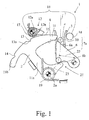
- the motor vehicle lock 1 shown in the drawings is assigned to a motor vehicle door arrangement, which comprises a motor vehicle door.
- a motor vehicle door Regarding the broad interpretation of the expression "motor vehicle door” reference is made to the introductory part of the specification.
- the motor vehicle door is a side door of the motor vehicle.
- the motor vehicle lock 1 comprises a catch 2, which is pivotable around a catch axis 2a.
- the motor vehicle lock 1 further comprises an inlet mouth 3 for a lock striker 4.
- the inlet mouth 3 may be constructed as a channel as shown in the drawings. Generally the inlet mouth 3 may as well just be a free area that allows the lock striker 4 to come into engagement with the catch 2 as will be described.
- the motor vehicle lock 1 in its installed state is arranged at the motor vehicle door, while the lock striker 4 is arranged at the body of the motor vehicle. Depending on the application this overall structure may be vice versa as well.
- a movement of the lock striker 4 relative to the motor vehicle lock 1 here and preferably goes back on the movement of the door of the motor vehicle door arrangement.
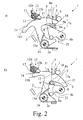
- the catch 2 can be brought into a preliminary closed position ( Fig. 2a ), into a main closed position ( Fig. 2b ) and into an open position ( fig. 1 ).
- the catch 2 as such in its closed positions ( Fig. 2a, 2b ) may hold the lock striker 4 by a holding engagement between the catch 2 and the lock striker 4.
- the direction of the holding forces acting from the lock striker 4 onto the catch 2 are indicated with reference number 5 in the drawings.
- catch 2 as such means here that the lock striker 4 is being held by the catch 2 alone. Accordingly, no additional catch 2 is provided to hold the lock striker 4. With this arrangement the resulting construction is simple and cost effective.
- the closing cycle of the motor vehicle lock is initiated by closing the motor vehicle door as noted in the general part of the specification.
- the lock striker 4 comes into an actuating engagement with the motor vehicle lock 1 such that the catch 2 moves from its open position into the direction of its closed position, here and preferably into its closed position.
- This closed position may be the main closed position of the catch 2. However, it may also be the preliminary closed position of the catch 2, in which case a motorized closing aid may be provided that moves the catch 2 into its main closed position.
- an actuating element 6 is provided, which is at least slightly displaceable relative to the catch 2.
- the actuating element 2 is or may be drivingly coupled to the catch 2, which coupling provides a transmission gearing, in particular a lever gearing, such that during the closing cycle the actuating engagement of the lock striker 4 with the actuating element 6 causes driving the catch 2 from its open position ( Fig. 1 ) into its main closed position ( Fig. 2b ) for establishing the holding engagement between the catch 2 and the lock striker 4.
- driving the catch 2 only into the direction of the closed position or into the preliminary closed position may be foreseen here as well.
- the lock striker 4 travels on a closing path 7 relative to the motor vehicle lock 1, wherein the holding forces 5 acting between the catch 2 and the lock striker 4 during the holding engagement are aligned to the closing path 7.
- the catch 2 comprises a holding engagement surface 8 for the holding engagement with the lock striker 4.
- the holding engagement surface 8 travels basically in a direction perpendicular to the closing path 7, in the drawings from left to right.
- Figs. 1 , 2a and 2b in combination show that the catch 2 during its movement from its open position into its closed position, with its holding engagement surface 8, crosses a crossing section 7a of the closing path 7. It may also be taken from this combination of figures that during the closing cycle the lock striker 4 passes the crossing section 7a of the closing path 7 before the catch 2 crosses the crossing section 7a. This synchronization is of particular importance for the function of the proposed motor vehicle lock.
- the lock striker 4 is in a holding position 9 for the main closed position (and in a holding position 9a for the preliminary closed position). It is preferred now that the actuating engagement between the lock striker 4 and the actuating element 6, when seen along the closing path 7, is taking place before the lock striker 4 reaching the holding position 9 (respective the holding position 9a).
- the first location of actuating engagement is denominated with the reference number 10 for clarification. With this sequence the above noted synchronization is possible with simple construction as will be explained in detail later.
- the catch 2 to be of basically hook shaped design with a hook portion 11 connected to a shaft portion 11 a, wherein the hook portion 11 provides the holding engagement surface 8 for the holding engagement between the catch 2 and the lock striker 4.
- the hook portion 11 is extending basically laterally with regard to the shaft portion 11a.
- a pawl 12 that is pivotable around a pawl axis 12a, may be provided, that is assigned to the catch 2.
- the pawl 12 may be brought into a blocking position ( Figs. 2a, 2b ), in which it is in blocking engagement with the catch 2. In the blocking position the pawl 12 prevents the catch 2 from pivoting from the respective closed position into the direction of the open position.
- the pawl 12 may also be deflected into a release position ( Fig. 1 ), in which it releases the catch 2.
- the catch 2 comprises a preliminary notch 13 and a main notch 14 for the blocking engagement between the pawl 12 and the catch 2.
- the at least one notch 13,14 is/are arranged on an outer contour 15 of the catch 2, in particular on an outer contour of the hook portion 11.
- at least the main notch 14 is arranged at an extension 11 b of the hook portion 11.
- the hook portion 11 and the extension 11b of the hook portion 11 extend from the shaft portion 11a into opposite directions.
- the striker 4 comes into engagement with a first holding engagement point 8a.
- the striker 4 comes into engagement with a second holding engagement point 8b.
- the second holding engagement point 8b is closer to the pivot axis 2a of the catch 2 than the first holding engagement point 8b.
- the distance between the preliminary notch 13, which is assigned to the preliminary closed position, and the main notch 14, which is assigned to the main closed position, is at least the distance between the above noted two holding engagement points 8a, 8b. This distance is fairly large, which may be advantageous as will be explained below.
- the pawl 12 normally falls into engagement with the preliminary notch 13 and subsequently is being guided to a radially outer position, such that it can fall into engagement with the main notch 14.
- This guidance may be accomplished by the preliminary notch 13 itself, which is provided with a ramp 13a as shown in Fig. 1 .
- the outer contour 15 between the preliminary notch 13 and the main notch 14 does not need to guide the pawl 12 anymore, such that it is mainly aligned to a circle around the pivot axis 2a of the catch 2.
- the outer contour 15 between the preliminary notch 13 and the main notch 14 is a continuous connection between the ground of the preliminary notch 13 to the top of the main notch 14. This connection provides the function of the above noted ramp 13a. As it is stretched along the above noted, fairly large distance, the acceleration on the pawl 12 in the radial direction is low even with quick closing cycles which leads to a safe engagement of the pawl 12 with the main notch 14 and which also leads to low noise generation during the closing cycle.
- the embodiment shown is provided with a special crash support arrangement 16 for those holding forces, that exceed a predetermined threshold and that lead to deformation of the motor vehicle lock.
- Those forces are assigned the direction of the holding forces 5 and act on the crash support arrangement 16 in particular when a deformation of the catch 2 or the pivot guide of the catch 2 has taken place.
- Such forces develop mainly in a crash situation, in particular because of crash accelerations.
- crash forces here and preferably are supported by the crash support arrangement 16 via the outer contour 15 of the catch 2.
- this is the same outer contour 15 which comprises the above noted, at least one notch 13,14.
- the crash support arrangement 16 comprises at least one support element 17,18. In order to achieve a symmetric support in view of the holding forces 5 it is further preferred that at least two crash support elements 17, 18 are arranged oppositely to each other with respect to the inlet mouth 3 for the lock striker 4.
- the pawl 12 itself provides a crash support element 17.
- the other, in the above noted sense oppositely to the pawl 12 arranged crash support element 18 is designed as a simple bolt.
- the embodiment shown in Figs. 1 and 2 provides a spring bias of the catch 2, namely, in its open position the catch 2 is spring biased into its open position by an opening spring arrangement 19.
- the proposed coupling between the actuating element 6 and the catch 2 provides a transmission gearing, in particular a lever gearing.
- the transmission gearing is laid out such that only a small force acting from the lock striker 4 onto the actuating element 6 is necessary in order to move the catch 2 from its open position ( Fig. 1 ) into its closed position ( Fig. 2b ).
- the actuating element 6 is an actuating lever with an actuating surface 6a for engagement with the lock striker 4.
- the actuating element 6 is provided with a transmission surface 6b for the engagement with the catch 2, which transmission surface 6b here and preferably is being realized by a bolt.
- the catch 2 is provided with a transmission lever 21 with a corresponding counter transmission surface 21a.
- the actuating surface 6a is inclined with respect to the closing path 7 to provide a wedge gearing between the striker 4 and the actuating element 6. Besides providing an additional transmission this inclination of the actuating surface 6a reduces the contact noise between the lock striker 4 and the actuating element 6 considerably.
- the angle ⁇ between the actuating surface 6a and the closing path 7 is between 20° and 60°.
- the expression "inclination” is to be understood in a wide sense here. It clarifies that there is an inclination between the actuating surface 6a and the closing path 7 at the point of contact between the striker 4 and the actuating element 6. This inclination may vary during the course of the closing cycle, especially if the actuating surface 6a is not ideally planar but curved or the like.
- the actuating element 6 with its transmission surface 6b slides along the counter transmission surface 21a of the catch 2.
- the actuating element 6 is linked to the catch 2 by a joint or the like.
- the gearing between the actuating element 6 and the catch 2 provides a torque converter, such that a torque applied on the actuating element 6 is being converted into a higher torque at the catch 2.
- the effective gearing lever 22 on the side of the actuating lever 6 is accordingly shorter than the effective gearing lever 23 on the side of the catch 2.
- the actuating lever 6 crosses the inlet mouth 3. This guarantees that during the closing cycle the lock striker 4 comes into actuating engagement with the actuating element 6 as noted above. For this effect it can also be sufficient that the actuating lever 6, which comprises the actuating surface 6a, extends somewhat into the inlet mouth 3.
- Figs. 1 , 2a, 2b Further preferred in the embodiment shown in Figs. 1 , 2a, 2b is the fact that the catch 2 is biased into its open position by an above noted opening spring arrangement 19.
- the synchronization of the bias of the opening spring arrangement 19 with the "affordable" force acting from the lock striker 4 onto the actuating element 6 is of particular importance for the function of the proposed motor vehicle lock.
Landscapes
- Lock And Its Accessories (AREA)
Applications Claiming Priority (1)
| Application Number | Priority Date | Filing Date | Title |
|---|---|---|---|
| US14/030,833 US10041279B2 (en) | 2013-09-18 | 2013-09-18 | Motor vehicle lock |
Publications (2)
| Publication Number | Publication Date |
|---|---|
| EP2851494A2 true EP2851494A2 (de) | 2015-03-25 |
| EP2851494A3 EP2851494A3 (de) | 2015-08-05 |
Family
ID=51584983
Family Applications (1)
| Application Number | Title | Priority Date | Filing Date |
|---|---|---|---|
| EP14185461.2A Withdrawn EP2851494A3 (de) | 2013-09-18 | 2014-09-18 | Kraftfahrzeugschloss |
Country Status (2)
| Country | Link |
|---|---|
| US (1) | US10041279B2 (de) |
| EP (1) | EP2851494A3 (de) |
Cited By (3)
| Publication number | Priority date | Publication date | Assignee | Title |
|---|---|---|---|---|
| WO2017108024A1 (de) * | 2015-12-22 | 2017-06-29 | Kiekert Ag | Kraftfahrzeugschloss mit drehfallenabstützung |
| EP3812540A1 (de) * | 2019-10-22 | 2021-04-28 | Kiekert AG | Kraftfahrzeug-schloss, insbesondere kraftfahrzeug-türschloss |
| WO2021180265A1 (de) * | 2020-03-11 | 2021-09-16 | Kiekert Aktiengesellschaft | Kraftfahrzeug-schloss insbesondere kraftfahrzeug-türschloss |
Families Citing this family (6)
| Publication number | Priority date | Publication date | Assignee | Title |
|---|---|---|---|---|
| CN106351521A (zh) * | 2016-08-29 | 2017-01-25 | 合肥创佳汽车电器有限公司 | 一种汽车门锁开启缓释结构 |
| CN106761051A (zh) * | 2016-12-19 | 2017-05-31 | 昆山麦格纳汽车系统有限公司 | 减噪汽车门锁 |
| DE102017120453A1 (de) * | 2017-09-06 | 2019-03-07 | Kiekert Ag | Kraftfahrzeugtürschloss |
| CN115978077A (zh) * | 2021-12-03 | 2023-04-18 | 广州极飞科技股份有限公司 | 一种锁扣组件 |
| US20230220717A1 (en) * | 2022-01-12 | 2023-07-13 | Magna Closures Inc. | Closure latch assembly with integrated door presenter |
| DE102022119847A1 (de) * | 2022-08-08 | 2024-02-08 | Kiekert Aktiengesellschaft | Kraftfahrzeugschloss mit verbessertem Türaufsteller |
Citations (5)
| Publication number | Priority date | Publication date | Assignee | Title |
|---|---|---|---|---|
| US2646299A (en) * | 1950-08-17 | 1953-07-21 | Ford Motor Co | Hood latch |
| US3345100A (en) * | 1965-10-20 | 1967-10-03 | Clarence F Kramer | Door lock mechanism |
| US4889371A (en) * | 1986-11-13 | 1989-12-26 | Vachette | Motorized closing device, particularly for an automotive-vehicle trunk |
| EP1867808B1 (de) | 2006-06-06 | 2009-05-13 | Brose Schliesssysteme GmbH & Co. KG | Kraftfahrzeugschloss |
| WO2011094736A1 (en) * | 2010-02-01 | 2011-08-04 | Strattec Security Corporation | Latch mechanism and latching method |
Family Cites Families (13)
| Publication number | Priority date | Publication date | Assignee | Title |
|---|---|---|---|---|
| US3394956A (en) * | 1967-03-22 | 1968-07-30 | Gen Motors Corp | Closure latch |
| JPS569634B2 (de) * | 1973-11-30 | 1981-03-03 | ||
| FR2488935A1 (fr) | 1980-08-22 | 1982-02-26 | Renault | Serrure de capot ou de coffre d'un vehicule automobile |
| US4875724A (en) * | 1986-10-29 | 1989-10-24 | Magna International Inc. | Hood latch mechanism |
| US5117665A (en) * | 1987-05-27 | 1992-06-02 | Swan Jye P | Vehicle door lock system |
| US4936611A (en) * | 1988-02-03 | 1990-06-26 | Magna International Inc. | Hood latch |
| JPH04293875A (ja) | 1991-03-20 | 1992-10-19 | Mitsui Mining & Smelting Co Ltd | 車両ドアロックの開扉時異音防止装置 |
| DE10019668A1 (de) | 2000-04-19 | 2001-10-31 | Hs Products Karosseriesysteme | Schließvorrichtung, insbesondere für eine Kofferraumklappe |
| FR2848235B1 (fr) | 2002-12-06 | 2005-08-26 | Renault Sa | Serrure pour capot de vehicule automobile |
| CN1946913B (zh) * | 2004-04-30 | 2011-08-10 | 英提尔汽车系统公司 | 外侧车门把手的旋转锁定机构 |
| US20060006669A1 (en) * | 2004-07-08 | 2006-01-12 | James Nelsen | Vehicle latch apparatus and method |
| DE102005016186A1 (de) * | 2005-04-08 | 2006-10-12 | Bayerische Motoren Werke Ag | Schloss mit einer Anschlageinrichtung, insbesondere an der vorderen Motorhaube eines Kraftfahrzeugs |
| DE102010061518B4 (de) | 2010-12-23 | 2022-03-24 | Witte Automotive Gmbh | Frontklappenschloss |
-
2013
- 2013-09-18 US US14/030,833 patent/US10041279B2/en active Active
-
2014
- 2014-09-18 EP EP14185461.2A patent/EP2851494A3/de not_active Withdrawn
Patent Citations (5)
| Publication number | Priority date | Publication date | Assignee | Title |
|---|---|---|---|---|
| US2646299A (en) * | 1950-08-17 | 1953-07-21 | Ford Motor Co | Hood latch |
| US3345100A (en) * | 1965-10-20 | 1967-10-03 | Clarence F Kramer | Door lock mechanism |
| US4889371A (en) * | 1986-11-13 | 1989-12-26 | Vachette | Motorized closing device, particularly for an automotive-vehicle trunk |
| EP1867808B1 (de) | 2006-06-06 | 2009-05-13 | Brose Schliesssysteme GmbH & Co. KG | Kraftfahrzeugschloss |
| WO2011094736A1 (en) * | 2010-02-01 | 2011-08-04 | Strattec Security Corporation | Latch mechanism and latching method |
Cited By (5)
| Publication number | Priority date | Publication date | Assignee | Title |
|---|---|---|---|---|
| WO2017108024A1 (de) * | 2015-12-22 | 2017-06-29 | Kiekert Ag | Kraftfahrzeugschloss mit drehfallenabstützung |
| CN109496247A (zh) * | 2015-12-22 | 2019-03-19 | 开开特股份公司 | 具有转动锁叉支撑结构的机动车锁 |
| US11371267B2 (en) | 2015-12-22 | 2022-06-28 | Kiekert Ag | Motor vehicle lock with rotary latch support |
| EP3812540A1 (de) * | 2019-10-22 | 2021-04-28 | Kiekert AG | Kraftfahrzeug-schloss, insbesondere kraftfahrzeug-türschloss |
| WO2021180265A1 (de) * | 2020-03-11 | 2021-09-16 | Kiekert Aktiengesellschaft | Kraftfahrzeug-schloss insbesondere kraftfahrzeug-türschloss |
Also Published As
| Publication number | Publication date |
|---|---|
| US10041279B2 (en) | 2018-08-07 |
| EP2851494A3 (de) | 2015-08-05 |
| US20150076837A1 (en) | 2015-03-19 |
Similar Documents
| Publication | Publication Date | Title |
|---|---|---|
| EP2851494A2 (de) | Kraftfahrzeugschloss | |
| US9382735B2 (en) | Motor vehicle lock | |
| EP2980341B1 (de) | Kraftfahrzeug-türschlossanordnung | |
| US9637952B2 (en) | Motor vehicle lock | |
| EP2784251B1 (de) | Kraftfahrzeugschloss | |
| US9366063B2 (en) | Motor vehicle lock | |
| CN104420741B (zh) | 机动车锁件 | |
| US20160090759A1 (en) | Motor vehicle lock | |
| US20150308161A1 (en) | Motor vehicle lock | |
| US10781614B2 (en) | Safety device for a motor vehicle, having a rotary latch and a protective position | |
| US20140284939A1 (en) | Motor vehicle lock | |
| US10294700B2 (en) | Vehicle door lock | |
| US11041329B2 (en) | Closing device for a motor vehicle hood | |
| CA2489497A1 (en) | Lift door drive device | |
| CN101542063A (zh) | 具有多个掣子的锁定装置 | |
| US20150337566A1 (en) | Motor vehicle door lock arrangement | |
| US20140284945A1 (en) | Motor vehicle lock | |
| US20140284942A1 (en) | Motor vehicle lock | |
| US11162276B2 (en) | Safety device for a motor vehicle having a rotary latch and an ejection spring | |
| EP1887171A2 (de) | Fahrzeugtürverschluss | |
| US10871011B2 (en) | Method for operating a motor vehicle lock | |
| AU2014352079B2 (en) | Flush bolt and door sealing system | |
| US10508475B2 (en) | Motor vehicle lock | |
| US20060055180A1 (en) | Motor vehicle lock | |
| EP2412902B1 (de) | Sektionaltor mit einer Eingangstür mit einem Verschlusssystem |
Legal Events
| Date | Code | Title | Description |
|---|---|---|---|
| PUAI | Public reference made under article 153(3) epc to a published international application that has entered the european phase |
Free format text: ORIGINAL CODE: 0009012 |
|
| 17P | Request for examination filed |
Effective date: 20140918 |
|
| AK | Designated contracting states |
Kind code of ref document: A2 Designated state(s): AL AT BE BG CH CY CZ DE DK EE ES FI FR GB GR HR HU IE IS IT LI LT LU LV MC MK MT NL NO PL PT RO RS SE SI SK SM TR |
|
| AX | Request for extension of the european patent |
Extension state: BA ME |
|
| PUAL | Search report despatched |
Free format text: ORIGINAL CODE: 0009013 |
|
| AK | Designated contracting states |
Kind code of ref document: A3 Designated state(s): AL AT BE BG CH CY CZ DE DK EE ES FI FR GB GR HR HU IE IS IT LI LT LU LV MC MK MT NL NO PL PT RO RS SE SI SK SM TR |
|
| AX | Request for extension of the european patent |
Extension state: BA ME |
|
| RIC1 | Information provided on ipc code assigned before grant |
Ipc: E05B 85/24 20140101AFI20150629BHEP Ipc: E05B 85/26 20140101ALI20150629BHEP Ipc: E05B 77/02 20140101ALN20150629BHEP Ipc: E05B 77/38 20140101ALI20150629BHEP Ipc: E05B 77/36 20140101ALI20150629BHEP |
|
| R17P | Request for examination filed (corrected) |
Effective date: 20160205 |
|
| RBV | Designated contracting states (corrected) |
Designated state(s): AL AT BE BG CH CY CZ DE DK EE ES FI FR GB GR HR HU IE IS IT LI LT LU LV MC MK MT NL NO PL PT RO RS SE SI SK SM TR |
|
| STAA | Information on the status of an ep patent application or granted ep patent |
Free format text: STATUS: EXAMINATION IS IN PROGRESS |
|
| 17Q | First examination report despatched |
Effective date: 20190819 |
|
| STAA | Information on the status of an ep patent application or granted ep patent |
Free format text: STATUS: THE APPLICATION IS DEEMED TO BE WITHDRAWN |
|
| 18D | Application deemed to be withdrawn |
Effective date: 20210731 |