EP2851692A1 - Système de recherche de défaut d'isolation doté d'une alimentation à sélection de branchement et système de surveillance d'isolation sélectif ainsi que procédé de détermination d'une impédance de ligne inter-automatique entre deux sous-systèmes - Google Patents
Système de recherche de défaut d'isolation doté d'une alimentation à sélection de branchement et système de surveillance d'isolation sélectif ainsi que procédé de détermination d'une impédance de ligne inter-automatique entre deux sous-systèmes Download PDFInfo
- Publication number
- EP2851692A1 EP2851692A1 EP20140177467 EP14177467A EP2851692A1 EP 2851692 A1 EP2851692 A1 EP 2851692A1 EP 20140177467 EP20140177467 EP 20140177467 EP 14177467 A EP14177467 A EP 14177467A EP 2851692 A1 EP2851692 A1 EP 2851692A1
- Authority
- EP
- European Patent Office
- Prior art keywords
- subsystem
- test signal
- insulation
- insulation fault
- subsystems
- Prior art date
- Legal status (The legal status is an assumption and is not a legal conclusion. Google has not performed a legal analysis and makes no representation as to the accuracy of the status listed.)
- Granted
Links
Images


Classifications
-
- G—PHYSICS
- G01—MEASURING; TESTING
- G01R—MEASURING ELECTRIC VARIABLES; MEASURING MAGNETIC VARIABLES
- G01R31/00—Arrangements for testing electric properties; Arrangements for locating electric faults; Arrangements for electrical testing characterised by what is being tested not provided for elsewhere
- G01R31/12—Testing dielectric strength or breakdown voltage ; Testing or monitoring effectiveness or level of insulation, e.g. of a cable or of an apparatus, for example using partial discharge measurements; Electrostatic testing
- G01R31/14—Circuits therefor, e.g. for generating test voltages, sensing circuits
-
- G—PHYSICS
- G01—MEASURING; TESTING
- G01R—MEASURING ELECTRIC VARIABLES; MEASURING MAGNETIC VARIABLES
- G01R19/00—Arrangements for measuring currents or voltages or for indicating presence or sign thereof
- G01R19/0092—Measuring current only
-
- G—PHYSICS
- G01—MEASURING; TESTING
- G01R—MEASURING ELECTRIC VARIABLES; MEASURING MAGNETIC VARIABLES
- G01R27/00—Arrangements for measuring resistance, reactance, impedance, or electric characteristics derived therefrom
- G01R27/02—Measuring real or complex resistance, reactance, impedance, or other two-pole characteristics derived therefrom, e.g. time constant
- G01R27/16—Measuring impedance of element or network through which a current is passing from another source, e.g. cable, power line
-
- G—PHYSICS
- G01—MEASURING; TESTING
- G01R—MEASURING ELECTRIC VARIABLES; MEASURING MAGNETIC VARIABLES
- G01R27/00—Arrangements for measuring resistance, reactance, impedance, or electric characteristics derived therefrom
- G01R27/02—Measuring real or complex resistance, reactance, impedance, or other two-pole characteristics derived therefrom, e.g. time constant
- G01R27/16—Measuring impedance of element or network through which a current is passing from another source, e.g. cable, power line
- G01R27/18—Measuring resistance to earth, i.e. line to ground
-
- G—PHYSICS
- G01—MEASURING; TESTING
- G01R—MEASURING ELECTRIC VARIABLES; MEASURING MAGNETIC VARIABLES
- G01R31/00—Arrangements for testing electric properties; Arrangements for locating electric faults; Arrangements for electrical testing characterised by what is being tested not provided for elsewhere
- G01R31/44—Testing lamps
-
- H—ELECTRICITY
- H02—GENERATION; CONVERSION OR DISTRIBUTION OF ELECTRIC POWER
- H02H—EMERGENCY PROTECTIVE CIRCUIT ARRANGEMENTS
- H02H3/00—Emergency protective circuit arrangements for automatic disconnection directly responsive to an undesired change from normal electric working condition with or without subsequent reconnection ; integrated protection
- H02H3/26—Emergency protective circuit arrangements for automatic disconnection directly responsive to an undesired change from normal electric working condition with or without subsequent reconnection ; integrated protection responsive to difference between voltages or between currents; responsive to phase angle between voltages or between currents
- H02H3/32—Emergency protective circuit arrangements for automatic disconnection directly responsive to an undesired change from normal electric working condition with or without subsequent reconnection ; integrated protection responsive to difference between voltages or between currents; responsive to phase angle between voltages or between currents involving comparison of the voltage or current values at corresponding points in different conductors of a single system, e.g. of currents in go and return conductors
- H02H3/33—Emergency protective circuit arrangements for automatic disconnection directly responsive to an undesired change from normal electric working condition with or without subsequent reconnection ; integrated protection responsive to difference between voltages or between currents; responsive to phase angle between voltages or between currents involving comparison of the voltage or current values at corresponding points in different conductors of a single system, e.g. of currents in go and return conductors using summation current transformers
- H02H3/334—Emergency protective circuit arrangements for automatic disconnection directly responsive to an undesired change from normal electric working condition with or without subsequent reconnection ; integrated protection responsive to difference between voltages or between currents; responsive to phase angle between voltages or between currents involving comparison of the voltage or current values at corresponding points in different conductors of a single system, e.g. of currents in go and return conductors using summation current transformers with means to produce an artificial imbalance for other protection or monitoring reasons or remote control
-
- G—PHYSICS
- G01—MEASURING; TESTING
- G01R—MEASURING ELECTRIC VARIABLES; MEASURING MAGNETIC VARIABLES
- G01R31/00—Arrangements for testing electric properties; Arrangements for locating electric faults; Arrangements for electrical testing characterised by what is being tested not provided for elsewhere
- G01R31/08—Locating faults in cables, transmission lines, or networks
-
- H—ELECTRICITY
- H02—GENERATION; CONVERSION OR DISTRIBUTION OF ELECTRIC POWER
- H02H—EMERGENCY PROTECTIVE CIRCUIT ARRANGEMENTS
- H02H7/00—Emergency protective circuit arrangements specially adapted for specific types of electric machines or apparatus or for sectionalised protection of cable or line systems, and effecting automatic switching in the event of an undesired change from normal working conditions
- H02H7/26—Sectionalised protection of cable or line systems, e.g. for disconnecting a section on which a short-circuit, earth fault, or arc discharge has occured
Definitions
- the invention relates to an insulation fault location system for a branched IT system with a subsystem (subnet) and with a differential current measuring device arranged in the subsystem for detecting a differential current measurement signal.
- the invention further comprises an insulation monitoring system for monitoring an insulation resistance in a branched IT system with a subsystem and with the features of the insulation fault location system and a method for determining a cross connection impedance between two subsystems in a branched IT system with the insulation monitoring system according to the invention.
- an active conductor may have an insulation fault without the current operation of the System must be interrupted, because due to the ideally infinitely large impedance value between the conductor and earth in this first error case can not form a closed circuit.
- An insulation fault is understood to be a faulty state of the IT system, which leads to a decrease in the insulation resistance below the permissible level of insulation.
- insulation fault location Along with the continuous insulation monitoring, a quick and reliable localization and removal of the insulation fault (insulation fault location) is essential.
- test current test current
- test current test current
- This test current signal can be detected by all measuring current transformers in this circuit.
- the aim of using an insulation fault location system in branched IT systems is the most sensitive detection of existing insulation faults in the subsystems and the determination of the subsystem with the largest insulation fault, ie the smallest insulation fault resistance. Since the test signal generator is almost always carried out with current limitation, the test current is divided between all the insulation fault resistances present in the IT system and the system leakage capacitances. The fault current flowing in a subnet is therefore not only dependent on the size of the fault resistance in this subnet, but also on further fault resistances and system leakage capacitances present in the IT system.
- the respective differential current measuring device in the subnet can only reliably detect insulation faults in the subnet to be monitored from a minimum residual current determined by the resolution and the measuring error of the measuring system. Therefore, the sensitivity of the isolation fault detection system is determined by the overall configuration of the IT system and can be adversely affected.
- the test signal is additionally dependent on the nominal voltage of the IT system to be monitored. Again, this is another parameter that affects the sensitivity of the isolation fault location system and increases the complexity of the isolation error search.
- Another peculiarity arises in insulation fault location systems, which feed pulse-shaped test signals, primarily in the form of a rectangular signal sequence, into the IT system.
- the transients must be taken into account by distributing existing system leakage capacitances.
- the ratio of the system leakage capacitance before and after the differential current measuring device in the subnet additionally determines the achievable sensitivity of the insulation fault location device.
- the problem with continuous insulation monitoring is that, according to the current state of the art, it is not possible to actively monitor the IT system of more than one insulation monitoring device at the same time.
- the active measuring systems of two or more active insulation monitoring devices in an IT system could influence each other in such a way that the monitoring task is not reliably guaranteed. Since the conductance of the parallel connection of all complex-valued insulation resistances in the overall system is always evaluated, the insulation monitoring device thus sees all existing system leakage capacitances in the IT system, the insulation monitoring device measuring system must be designed so that it can counteract the interference influences generated by the subsystems.
- the selective monitoring of IT subsystems is required in such a way that an insulation fault in an IT subsystem should lead to rapid shutdown of the affected subsystem and without influencing other IT subsystems.
- the present invention is therefore based on the object of designing an insulation fault location device which enables fast and reliable detection of insulation faults in a branched, multi-subsystem IT system. Furthermore, the object is to design for a branched IT system, an insulation monitoring device that allows fast and reliable monitoring of the entire isolation state of the IT system. Furthermore, a method is desirable, which provides more information on the isolation state of the IT system in addition to the determination of the insulation resistance.
- This object is related to the isolation error search in conjunction with the preamble of claim 1, characterized in that in the subsystem, a test signal generator for the serial feed of a test signal is arranged and that the subsystem has a blocking device, the effectiveness of the fed into this subsystem test signal on this Subsystem limited.
- an isolation fault search optimized for the respective subsystem can be carried out in conjunction with the differential current measuring device likewise present in each subsystem. Unaffected by the electrical state of the rest of the IT system, a fast and reliable detection of insulation faults is thus possible.
- the metrological interpretation of the Insulation fault location system is thus designed so that the electrical characteristics of each subsystem can be taken into account.
- the measurement and monitoring cycles can be adapted to the respective subsystem and freely set independently of the other subsystems.
- a test signal may be fed in at shorter intervals and a very fast measurement can be realized.
- robust, low-interference subsystems e.g. can be worked with larger fürsignalamplituden
- sensitive subsystems advantageously lower test signal amplitudes can be selected.
- test signal amplitude and test signal frequency can be optimally adapted to the conditions (network leakage capacitance, disturbances) of the subsystem to be monitored without influencing the measurement task in other subsystems.
- the blocking device thus prevents a reaction of the optimized for the respective subsystem test signal to the rest of the IT system.
- isolation fault detection system Due to the isolation fault detection system with two-selective, serial impression of a test signal in each subnet separately, while the effectiveness of the impressed test signal on the relevant subnetwork is largely limited by the blocking device, a reliable and fast isolation fault search can be carried out in the overall system.
- test signal generator is designed to generate test signals having a different waveform and adjustable signal parameters.
- Each test signal generator thus allows an individual, adapted to the electrical properties of the respective subsystem generation and feeding of a test signal optimally suitable for the respective subsystem. It is thus possible to make the test signal form, further test signal parameters and the associated evaluation methods adjustable and freely selectable in order to be able to realize the most robust possible detection of the insulation faults in the entire IT system. Furthermore, this embodiment of the investigasignalgenerators offers the possibility of sequential switching to different test signals to meet other measurement and monitoring tasks. By way of example, the multiple measurement with different test signals for the selective determination of leakage-current leading cross-connections between two subsystems may be mentioned here.
- test signal generator is designed as a sine signal generator or as a pulse signal generator.
- the blocking device has an adjustable selectivity which determines the strength of the limitation of the effectiveness of the test signal.
- This adjustable test signal selectivity can be used to determine how much the test signal of the blocking device is to be decoupled from the rest of the power supply network in a considered subsystem. This can be done for example by a Modification and presetting of the effective at the test signal frequency impedance of the blocking device done.
- the blocking device is designed as a series resonant circuit. Based on the electrical properties of the IT system as well as the expected interference and thus depending on the scholarsignalform the blocking device in the case of a sinusoidal test signal from a passive series resonant circuit whose resonant frequency corresponds to the frequency of the injected test signal and by his in the case of resonance by the ohmic resistance certain minimum impedance causes only a small part of the test current flows into the rest of the "preceding" IT system.
- the blocking device is advantageously designed as a comb filter.
- the active comb filter effects a low-resistance connection to ground potential for the respective test signal components of the relevant subsystem and prevents the rest of the IT system from being influenced by the test signal.
- test signal is designed as a serial feed of a common-mode signal.
- the test signal is superimposed on all active conductors of the subnet with the same phase.
- the object is achieved in conjunction with the characteristics of the insulation fault location system according to claims 1 to 8, characterized in that the subsystem has a selective decoupling device, which occurs when an insulation fault in a subsystem This subsystem is metrologically decoupled from the rest of the IT system and thus prevents an influence on the measurements in the rest of the IT system.
- the isolation fault detection system can be extended to a selective isolation monitoring system.
- the test current generated in the respective test current generator and fed in series into the subsystem can be configured as a measuring current for the insulation monitoring.
- this measuring current is not measured at the measuring resistor of an insulation monitoring device, but, like the test current mentioned above, is likewise detected by the differential current measuring device of the respective subsystem.
- the insulation monitoring system has the decoupling device in addition to the features of the insulation fault location system.
- the selective decoupling device With regard to the actual supply task, that is to say at the operating system frequency of the IT system to be monitored, the selective decoupling device must as far as possible behave like a low-resistance line resistance so as not to impair the intended operation of the IT system, e.g. the energy supply of the affected branch, inadmissible influence. With the aid of the selective decoupling device, it is also possible to simultaneously monitor existing high-impedance, error-free subsystems in the event of a low-resistance insulation fault in a subsystem.
- the claimed insulation monitoring system can be used both in ungrounded and in grounded systems.
- a parallel insulation monitoring in different subsystems is possible.
- the insulation monitoring system according to the invention can be optimally adapted to the conditions of the individual subsystem. Lying e.g. In a subsystem only low leakage capacitances before, so the isolation monitoring for this subnet can deliver results very quickly, even if there are very large network leakage capacity in other subnets. This also solves the problem of selectively acting insulation monitoring. A second error can thus be reliably detected.
- the selective decoupling device has an adjustable selectivity, which determines the degree of decoupling.
- a sufficiently high-impedance impedance is generated in the selective decoupling device for the test signals.
- the faulty branch for the test signals of the rest of the network therefore represents a high-impedance impedance.
- This impedance is, for example, with regard to its frequency dependence to the respective measuring system. and monitoring task customizable.
- the decoupling device must be sufficiently low-impedance in order not to unduly influence the intended operation of the entire IT system.
- the decoupling device when a sinusoidal test signal is fed in, is preferably designed as a parallel resonant circuit.
- This embodiment makes it possible to generate a high-impedance impedance at exactly the resonant frequency of the parallel resonant circuit, which corresponds to the frequency of the injected sinusoidal test signal.
- the object is achieved in that the two subsystems in a sequential multiple measurement first with the same test signal at the same setting the selectivity of the blocking device and the Decoupling device are acted upon, are subsequently acted upon with different test signals at different settings of the selectivities and the cross-connection impedance is determined from the difference of the measured insulation resistance values.
- two subsystems can first be operated respectively with the same test signal and the same settings of the test signal selectivities of the blocking device and the decoupling device, in a second step with different test signals and different test signal selectivities and in a third step, from a comparison of those in the steps one and two measured insulation resistance values are determined, the cross-connection impedance - wherein the order of the first two steps is interchangeable.
- test current components flow not only via possibly existing leakage impedances to earth but also over any existing cross-connections between the two subsystems.
- test signal components that are used in other subsystems are shielded for the subsystem considered, so that cross-connections to other subsystems have little influence on the measurement of the insulation resistance in the considered subsystem.
- the Fig. 1 shows the structure of a typical, corresponding to the prior art insulation fault location system for a branched IT system 4 with n subsystems (subnets) S 1 , .., S n .
- the IT system 4 is formed by way of example as a 3-phase power supply network with the outer conductors L 1 , L 2 , L 3 , the neutral conductor N and the protective conductor PE.
- the active conductors L 1 , L 2 , L 3 and N connect the current source 8 via a branched line system with the respective consumers V 1 , .., V n in the individual subsystems S 1 , .., S n .
- a test signal generator G for feeding a test signal is arranged in the main system.
- the test signal in the faulty subsystem S 1 ,..., S n of a differential current measuring device M 1 , .. , M n recorded and can then be evaluated in a central evaluation unit.
- the illustrated network configuration is further characterized by the system leakage capacitances C v and C n1 , .., C nn , where the distributed network leakage capacitances C v , C n1 , .., C nn are described here as lumped elements which precedes (C v ) and after (C n1 , .., C nn ) the differential current devices M 1 , .., M n are arranged.
- FIG. 2 An insulation fault location system 2 according to the invention with a branch-selective feed is shown.
- the insulation fault detection system 2 according to the invention for each subsystem S 1 , .., S n a test signal generator G 1 , .., G n for the serial feed of an individually to the electrical characteristics of the IT system 4, in particular the respective subsystem S 1 , .. , S n , tuned test signal.
- the test signal generator G 1 , .., G n serially feeds a common mode test signal into each subnet phase.
- This common mode test signal may be, for example, a sinusoidal 1V / 1 kHz test signal or a pulse signal.
- each subsystem S 1 , .., S n comprises a blocking device B 1 , .., B n , in order to prevent a reaction of the fed into the respective subsystem S 1 , .., S n test signal to the rest of the IT system.
- the blocking device B 1 ,..., B n concerned is preferably realized as a series resonant circuit with respect to earth with a resonance frequency of 1 kHz. Simulation results show that in a design of the series resonant circuit with an ohmic resistance of 100 mOhm and modeling the upstream network leakage capacity of 20 uF only approximately 1/80 of the 1 kHz test current from the subsystem S 1 , .., S n in the front of it flows.
- each subsystem S 1 , .., S n a suitable for detecting the test current differential current measuring device M 1 , .., M n arranged.
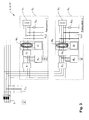
- FIG. 3 shows that in Fig. 2 illustrated isolation fault detection system 2, which has been extended by a decoupling device E 1 , .., E n arranged in each subsystem S 1 , .., S n and thus leads to the realization of a selective isolation monitoring system 12 according to the invention.
- a saturated ground fault occurs in a subsystem S 1 ,..., S n , ie, a subnet phase is connected to earth with negligible resistance
- the encapsulation of the individual subnets S 1 ,..., S n with the series resonant circuit of the blocking device B 1 .., B n against earth as a sole measure no longer be sufficiently effective.
- the encapsulation of the faulty subnet S 1 , .., S n is guaranteed even in this critical case.
- this additional decoupling provides additional measurement reliability, but is not necessary in principle.
- a decoupling device E 1 , .., E n in the form of a parallel resonant circuit, it is advantageous to use inductors coupled instead of single inductances.
- These "current-compensated chokes" provide a barely effective inductance component for the line-frequency (push-pull) load current, while the full inductance is effective for the test signal-frequency (common-mode) measuring current.
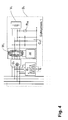
- the Fig. 4 shows an embodiment of a subnet S 1 , .., S n for pulse-shaped test signals.
- the blocking device B 1 is designed as an active comb filter which effects a low-impedance connection to ground potential only for the test signal components of the relevant subsystem S 1 ,..., S n .
Landscapes
- Physics & Mathematics (AREA)
- General Physics & Mathematics (AREA)
- Engineering & Computer Science (AREA)
- Power Engineering (AREA)
- Locating Faults (AREA)
- Testing Of Short-Circuits, Discontinuities, Leakage, Or Incorrect Line Connections (AREA)
Applications Claiming Priority (1)
| Application Number | Priority Date | Filing Date | Title |
|---|---|---|---|
| DE201310218836 DE102013218836A1 (de) | 2013-09-19 | 2013-09-19 | Isolationsfehlersuchsystem mit zweigselektiver Einspeisung und selektives Isolationsüberwachungssystem sowie Verfahren zur Bestimmung einer Querverbindungsimpedanz zwischen zwei Subsystemen |
Publications (2)
| Publication Number | Publication Date |
|---|---|
| EP2851692A1 true EP2851692A1 (fr) | 2015-03-25 |
| EP2851692B1 EP2851692B1 (fr) | 2019-06-12 |
Family
ID=51257282
Family Applications (1)
| Application Number | Title | Priority Date | Filing Date |
|---|---|---|---|
| EP14177467.9A Active EP2851692B1 (fr) | 2013-09-19 | 2014-07-17 | Système de recherche de défaut d'isolation doté d'une alimentation à sélection de branchement et système de surveillance d'isolation sélectif ainsi que procédé de détermination d'une impédance de ligne inter-automatique entre deux sous-systèmes |
Country Status (4)
| Country | Link |
|---|---|
| US (1) | US10151790B2 (fr) |
| EP (1) | EP2851692B1 (fr) |
| CN (1) | CN104459459B (fr) |
| DE (1) | DE102013218836A1 (fr) |
Cited By (2)
| Publication number | Priority date | Publication date | Assignee | Title |
|---|---|---|---|---|
| EP3139188A1 (fr) * | 2015-09-03 | 2017-03-08 | Bender GmbH & Co. KG | Procédé et dispositif de recherche d'erreur d'isolation comprenant une détermination adaptative de courant de test |
| EP4175095A1 (fr) * | 2021-10-26 | 2023-05-03 | Bender GmbH & Co. KG | Procédé et dispositif de détection et de localisation d'erreurs cycliques d'isolation de courte durée dans un système d'alimentation électrique non mis à la terre |
Families Citing this family (30)
| Publication number | Priority date | Publication date | Assignee | Title |
|---|---|---|---|---|
| DE102014223287A1 (de) | 2014-11-14 | 2016-05-19 | Bender Gmbh & Co. Kg | Elektrische Schutzeinrichtung und Verfahren zur selektiven Abschaltung eines Subsystems bei einem zweiten Fehler in einem IT-Stromversorgungssystem |
| DE102015214615A1 (de) | 2015-07-31 | 2017-02-02 | Bender Gmbh & Co. Kg | Verfahren und Vorrichtungen zur erweiterten Isolationsfehlersuche mit multifunktionalem Prüfstrom |
| MX386339B (es) | 2017-03-31 | 2025-03-18 | Corning Optical Communications LLC | Desconexión segura de potencia para distribución de potencia sobre conductores de potencia a dispostivos de consumo de potencia. |
| DE102017205931B3 (de) | 2017-04-06 | 2018-07-26 | Bender Gmbh & Co. Kg | Isolationsfehlersuchsysteme und Verfahren zur Isolationsfehlersuche für ein redundantes Dioden gekoppeltes Gleichstrom-Stromversorgungssystem |
| DE102017209243B4 (de) * | 2017-05-31 | 2018-12-20 | Bender Gmbh & Co. Kg | Verfahren und Messanordnung zur Überwachung eines Fertigungsablaufs einer modular aufgebauten Spannungsquelle |
| DE102017209663B3 (de) * | 2017-06-08 | 2018-10-18 | Bender Gmbh & Co. Kg | Verfahren zur Isolationsfehlersuche und Isolationsfehlersucheinrichtung für ein ungeerdetes Stromversorgungssystem |
| CN109239538B (zh) * | 2017-07-10 | 2022-08-09 | 比亚迪股份有限公司 | 列车以及列车的绝缘检测系统 |
| CN109239562B (zh) * | 2017-07-10 | 2022-08-09 | 比亚迪股份有限公司 | 列车以及列车的绝缘检测系统 |
| CN109239537B (zh) * | 2017-07-10 | 2022-08-09 | 比亚迪股份有限公司 | 列车以及列车的绝缘检测系统 |
| DE102017217473B3 (de) | 2017-09-29 | 2019-01-17 | Bender Gmbh & Co. Kg | Verfahren und Überwachungsvorrichtung zur selektiven Bestimmung einer Teil-Netzableitkapazität in einem ungeerdeten Stromversorgungssystem |
| CN109061465B (zh) * | 2018-07-10 | 2020-07-24 | 江苏中车电机有限公司 | 一种检测电机定子绝缘薄弱点位置的检测方法 |
| DE102018121979A1 (de) | 2018-09-10 | 2020-03-12 | Bender Gmbh & Co. Kg | Verfahren zur Isolationsüberwachung eines Umrichter-gespeisten Stromversorgungssystems |
| WO2020086780A1 (fr) | 2018-10-25 | 2020-04-30 | Corning Optical Communications LLC | Système de distribution d'énergie |
| DE102018130690B3 (de) * | 2018-12-03 | 2020-03-26 | Bender Gmbh & Co. Kg | Magnetfeld-Messvorrichtung und Verfahren zur Erfassung eines Lokalisierungsstroms in einem verzweigten Wechselstrom-Stromversorgungssystem |
| CN112285481A (zh) * | 2019-07-12 | 2021-01-29 | 北京德意新能科技有限公司 | 一种用于直流线路绝缘监测与故障定位的装置 |
| US11973343B2 (en) | 2019-08-05 | 2024-04-30 | Corning Research & Development Corporation | Safety power disconnection for power distribution over power conductors to radio communications circuits |
| CN110456270B (zh) * | 2019-08-09 | 2020-06-16 | 清华大学 | 一种电机绝缘在线监测方法及装置 |
| DE102019129413B4 (de) * | 2019-10-31 | 2021-10-07 | Dr. Ing. H.C. F. Porsche Aktiengesellschaft | Kompensationsvorrichtung für Ableitströme |
| CN111127802A (zh) * | 2019-12-03 | 2020-05-08 | 安徽北斗易通信息技术有限公司 | 一种基于串联谐振机理的配电电气火灾预警方法及装置 |
| US11791656B2 (en) | 2020-04-23 | 2023-10-17 | Corning Research & Development Corporation | Systems and methods for synchronizing subunits in a multi-unit power distribution network |
| US11855455B2 (en) | 2020-04-23 | 2023-12-26 | Corning Research & Development Corporation | Systems and methods for power start up in a multi-unit power distribution network |
| CN111426881A (zh) * | 2020-05-13 | 2020-07-17 | 常熟瑞特电气股份有限公司 | Rim型绝缘监测方法及装置 |
| CN111426882A (zh) * | 2020-05-13 | 2020-07-17 | 常熟瑞特电气股份有限公司 | Rim型绝缘监测系统 |
| US11621776B2 (en) | 2020-07-29 | 2023-04-04 | Corning Research & Development Corporation | Systems for low power distribution in a power distribution network |
| CN113193882B (zh) * | 2021-04-02 | 2023-07-14 | 渝丰科技股份有限公司 | 基于电力载波通信的野外求助定位方法 |
| US12126168B2 (en) | 2021-11-30 | 2024-10-22 | Corning Research & Development Corporation | Power distribution within a power source unit |
| DE102022117233B3 (de) | 2022-07-11 | 2023-12-21 | Bender Gmbh & Co. Kg | Verfahren und elektrische Schaltungsanordnung zur Bestimmung eines Zweig-Isolationswiderstands und einer Zweig-Ableitkapazität in einem ungeerdeten Stromversorgungssystem |
| DE102022128107B3 (de) * | 2022-10-25 | 2024-02-01 | Bender Gmbh & Co. Kg | Verfahren und elektrische Schaltungsanordnung zur zweigselektiven Bestimmung resistiver und kapazitiver, isolationsbestimmender Größen in einem verzweigten ungeerdeten Stromversorgungssystem |
| DE102023116532B3 (de) | 2023-06-23 | 2024-10-02 | Bender Gmbh & Co. Kg | Verfahren und elektrische Schaltungsanordnung zur selektiven Isolationsüberwachung in einem Stromversorgungssystem mit abtrennbaren Subsystemen |
| DE102024202460A1 (de) * | 2024-03-15 | 2025-09-18 | Siemens Aktiengesellschaft | Isolationsfehlerlokalisierung in einem IT-Netz |
Citations (4)
| Publication number | Priority date | Publication date | Assignee | Title |
|---|---|---|---|---|
| DE1945803A1 (de) * | 1969-09-05 | 1971-03-11 | Siemens Ag | Schaltungsanordnung zur UEberwachung des Laeuferkreises von Gleichstrommaschinen |
| EP1936393A1 (fr) * | 2006-12-22 | 2008-06-25 | Abb Research Ltd. | Appareil et procédé de mesure d'impédance |
| WO2010069739A1 (fr) * | 2008-12-18 | 2010-06-24 | Abb Research Ltd | Système de détection de défauts de mise à la terre dans un générateur |
| EP2530801A1 (fr) * | 2011-05-31 | 2012-12-05 | ABB Schweiz AG | Protection contre les défauts de terre |
Family Cites Families (12)
| Publication number | Priority date | Publication date | Assignee | Title |
|---|---|---|---|---|
| JP3158986B2 (ja) * | 1995-08-30 | 2001-04-23 | 株式会社日立製作所 | ガス絶縁開閉装置 |
| JP3763852B2 (ja) * | 1997-06-17 | 2006-04-05 | ディプロム−インジェニエール ヴァルター ベンダー ゲゼルシャフト ミット ベシュレンクテル ハフツング ウント コンパニー コマンディートゲゼルシャフト | 交流電源における絶縁および障害電流の監視方法および監視回路 |
| US7843197B2 (en) * | 2004-06-15 | 2010-11-30 | Pass & Seymour, Inc. | Protective device with end-of-life indication before power denial |
| DE102004018918B3 (de) * | 2004-04-19 | 2005-07-28 | Ean Elektroschaltanlagen Grimma Gmbh | Verfahren und Einrichtung zur Isolationsfehlerortung in einem isolierten ungeerdeten Wechselstromnetz |
| JP5368295B2 (ja) * | 2006-03-16 | 2013-12-18 | パワー・モニターズ・インコーポレーテッド | 地下監視システム及び方法 |
| US9261562B2 (en) * | 2008-10-04 | 2016-02-16 | Skf Usa, Inc. | Portable system for immotive multiphasic motive force electrical machine testing |
| DE102010011476A1 (de) * | 2010-03-16 | 2011-09-22 | Adensis Gmbh | Isolationstestverfahren für Photovoltaikgroßanlagen |
| CN201955425U (zh) * | 2011-01-27 | 2011-08-31 | 保定天威集团有限公司 | 医院隔离供电系统中的绝缘故障定位装置 |
| US20120287544A1 (en) * | 2011-05-13 | 2012-11-15 | Huang Jui-Kun | Isolation-type ac fault current limited circuit |
| DE102011050590A1 (de) | 2011-05-24 | 2012-11-29 | Sma Solar Technology Ag | Isolationsüberwachung mit einem Prüfsignal variabler Frequenz |
| DE102011083792A1 (de) * | 2011-09-29 | 2013-04-04 | Bender Gmbh & Co. Kg | Isolationsfehlersuchgerät und Vorrichtung zur Isolationsfehlerlokalisierung in einem ungeerdeten Stromversorgungsnetz |
| CN102508118A (zh) * | 2011-12-09 | 2012-06-20 | 江苏镇安电力设备有限公司 | 一种配出中性导体的it电力系统接地故障选线方法 |
-
2013
- 2013-09-19 DE DE201310218836 patent/DE102013218836A1/de not_active Withdrawn
-
2014
- 2014-07-17 EP EP14177467.9A patent/EP2851692B1/fr active Active
- 2014-09-16 US US14/487,177 patent/US10151790B2/en active Active
- 2014-09-18 CN CN201410478952.4A patent/CN104459459B/zh not_active Expired - Fee Related
Patent Citations (4)
| Publication number | Priority date | Publication date | Assignee | Title |
|---|---|---|---|---|
| DE1945803A1 (de) * | 1969-09-05 | 1971-03-11 | Siemens Ag | Schaltungsanordnung zur UEberwachung des Laeuferkreises von Gleichstrommaschinen |
| EP1936393A1 (fr) * | 2006-12-22 | 2008-06-25 | Abb Research Ltd. | Appareil et procédé de mesure d'impédance |
| WO2010069739A1 (fr) * | 2008-12-18 | 2010-06-24 | Abb Research Ltd | Système de détection de défauts de mise à la terre dans un générateur |
| EP2530801A1 (fr) * | 2011-05-31 | 2012-12-05 | ABB Schweiz AG | Protection contre les défauts de terre |
Non-Patent Citations (1)
| Title |
|---|
| BALDWIN T ET AL: "Analysis of fault locating signals for high-impedance grounded systems", CONFERENCE RECORD OF THE 2001 IEEE INDUSTRY APPLICATIONS CONFERENCE. 36TH IAS ANNUAL MEETING . CHICAGO, IL, SEPT. 30 - OCT. 4, 2001; [CONFERENCE RECORD OF THE IEEE INDUSTRY APPLICATIONS CONFERENCE. IAS ANNUAL MEETING], NEW YORK, NY : IEEE, US, vol. 3, 30 September 2001 (2001-09-30), pages 1823 - 1830, XP010561937, ISBN: 978-0-7803-7114-9, DOI: 10.1109/IAS.2001.955779 * |
Cited By (4)
| Publication number | Priority date | Publication date | Assignee | Title |
|---|---|---|---|---|
| EP3139188A1 (fr) * | 2015-09-03 | 2017-03-08 | Bender GmbH & Co. KG | Procédé et dispositif de recherche d'erreur d'isolation comprenant une détermination adaptative de courant de test |
| US10598718B2 (en) | 2015-09-03 | 2020-03-24 | Bender Gmbh & Co. Kg | Method and device for insulation fault location having an adaptive test current determination |
| EP4175095A1 (fr) * | 2021-10-26 | 2023-05-03 | Bender GmbH & Co. KG | Procédé et dispositif de détection et de localisation d'erreurs cycliques d'isolation de courte durée dans un système d'alimentation électrique non mis à la terre |
| US11867718B2 (en) | 2021-10-26 | 2024-01-09 | Bender GmbH + Co. KG | Method and device for identifying and locating cyclic momentary insulation faults in an underground power supply system |
Also Published As
| Publication number | Publication date |
|---|---|
| US20150077130A1 (en) | 2015-03-19 |
| EP2851692B1 (fr) | 2019-06-12 |
| US10151790B2 (en) | 2018-12-11 |
| CN104459459B (zh) | 2019-11-01 |
| DE102013218836A1 (de) | 2015-03-19 |
| CN104459459A (zh) | 2015-03-25 |
Similar Documents
| Publication | Publication Date | Title |
|---|---|---|
| EP2851692B1 (fr) | Système de recherche de défaut d'isolation doté d'une alimentation à sélection de branchement et système de surveillance d'isolation sélectif ainsi que procédé de détermination d'une impédance de ligne inter-automatique entre deux sous-systèmes | |
| EP2884290B1 (fr) | Dispositif et procédé de surveillance de l'isolation dans un système d'alimentation en courant ayant un point neutre mis à la terre à haute impédance | |
| EP2230522B1 (fr) | Procédé et dispositif de surveillance d'isolation d'un réseau isolé terre | |
| EP1909369B1 (fr) | Agencement de commutation et procédé de surveillance d'isolation pour des applications de convertisseur en fonctionnement | |
| EP2476002B1 (fr) | Identification de défauts dans des réseaux d'alimentation en énergie présentant un point neutre non relié à la terre ou une disparition du point neutre | |
| EP2585841B1 (fr) | Dispositif et procédé de surveillance d'une installation photovoltaïque | |
| DE102014223287A1 (de) | Elektrische Schutzeinrichtung und Verfahren zur selektiven Abschaltung eines Subsystems bei einem zweiten Fehler in einem IT-Stromversorgungssystem | |
| EP3867651B1 (fr) | Dispositif de mesure, installation électrique comprenant un dispositif de mesure et procédé de mesure d'un courant de fuite | |
| EP1090303B1 (fr) | Procede et dispositif pour la surveillance d'une ligne d'electrode d'une installation bipolaire de transport de courant continu a haute tension (c.c.h.t) | |
| EP3524985A1 (fr) | Dispositif et procédé pour une surveillance de l'isolation à reconnaissance d'un conducteur extérieur défectueux dans un système d'alimentation électrique non mis à la masse triphasé | |
| DE102014204038A1 (de) | Verfahren und Vorrichtungen zur selektiven Isolationsüberwachung in ungeerdeten IT-Stromversorgungssystemen | |
| EP3832324A1 (fr) | Agencement de circuit à tension de mesure active permettant de déterminer la résistance d'isolation par rapport à la terre dans un système d'alimentation en courant non mis à la terre | |
| EP3139188A1 (fr) | Procédé et dispositif de recherche d'erreur d'isolation comprenant une détermination adaptative de courant de test | |
| DE102019121961A1 (de) | Kompensationsvorrichtung zur Kompensation von Ableitströmen | |
| DE102017112256A1 (de) | Verfahren zur erkennung eines kontaktfehlers in einer photovoltaikanlage | |
| DE102019132071B4 (de) | Vorrichtung zum Überwachen eines Versorgungsnetzes | |
| DE112019000888T5 (de) | System zur Erdung und Diagnose | |
| EP3723221A1 (fr) | Détection d'une perte à la terre dans un réseau à courant continu | |
| EP3723220B1 (fr) | Emplacements d'une perte à la terre dans un réseau à courant continue | |
| EP3723223A1 (fr) | Emplacements d'une perte à la terre dans un réseau à courant continue | |
| EP3943954B1 (fr) | Agencement de circuit permettant de localiser des défauts d'isolation | |
| DE60001279T2 (de) | Erdfehler-schutzeinrichtung für die wicklung einer elektrischen maschine | |
| DE102021114260A1 (de) | Elektrische Schaltungsanordnung zur normgerechten Isolationsüberwachung mit Schnellabschaltung bei Erdschlusserkennung für ein ungeerdetes Stromversorgungssystem | |
| DE102015101870A1 (de) | Verfahren zur Kompensation eines über eine Ableitkapazität fließenden Anteils an einem Differenzstrom und zur Durchführung des Verfahrens geeigneter Wechselrichter | |
| DE10253864A1 (de) | Verfahren und Anordnung zur Erdschlussüberwachung eines Stators in Sternschaltung |
Legal Events
| Date | Code | Title | Description |
|---|---|---|---|
| PUAI | Public reference made under article 153(3) epc to a published international application that has entered the european phase |
Free format text: ORIGINAL CODE: 0009012 |
|
| 17P | Request for examination filed |
Effective date: 20140717 |
|
| AK | Designated contracting states |
Kind code of ref document: A1 Designated state(s): AL AT BE BG CH CY CZ DE DK EE ES FI FR GB GR HR HU IE IS IT LI LT LU LV MC MK MT NL NO PL PT RO RS SE SI SK SM TR |
|
| AX | Request for extension of the european patent |
Extension state: BA ME |
|
| R17P | Request for examination filed (corrected) |
Effective date: 20150909 |
|
| RBV | Designated contracting states (corrected) |
Designated state(s): AL AT BE BG CH CY CZ DE DK EE ES FI FR GB GR HR HU IE IS IT LI LT LU LV MC MK MT NL NO PL PT RO RS SE SI SK SM TR |
|
| STAA | Information on the status of an ep patent application or granted ep patent |
Free format text: STATUS: EXAMINATION IS IN PROGRESS |
|
| 17Q | First examination report despatched |
Effective date: 20180523 |
|
| GRAP | Despatch of communication of intention to grant a patent |
Free format text: ORIGINAL CODE: EPIDOSNIGR1 |
|
| STAA | Information on the status of an ep patent application or granted ep patent |
Free format text: STATUS: GRANT OF PATENT IS INTENDED |
|
| RIC1 | Information provided on ipc code assigned before grant |
Ipc: H02H 7/26 20060101ALI20181205BHEP Ipc: H02H 3/17 20060101ALI20181205BHEP Ipc: G01R 27/18 20060101AFI20181205BHEP Ipc: G01R 31/08 20060101ALI20181205BHEP Ipc: G01R 31/14 20060101ALI20181205BHEP Ipc: H02H 3/33 20060101ALI20181205BHEP |
|
| INTG | Intention to grant announced |
Effective date: 20190103 |
|
| GRAS | Grant fee paid |
Free format text: ORIGINAL CODE: EPIDOSNIGR3 |
|
| GRAA | (expected) grant |
Free format text: ORIGINAL CODE: 0009210 |
|
| STAA | Information on the status of an ep patent application or granted ep patent |
Free format text: STATUS: THE PATENT HAS BEEN GRANTED |
|
| AK | Designated contracting states |
Kind code of ref document: B1 Designated state(s): AL AT BE BG CH CY CZ DE DK EE ES FI FR GB GR HR HU IE IS IT LI LT LU LV MC MK MT NL NO PL PT RO RS SE SI SK SM TR |
|
| REG | Reference to a national code |
Ref country code: GB Ref legal event code: FG4D Free format text: NOT ENGLISH |
|
| REG | Reference to a national code |
Ref country code: CH Ref legal event code: EP |
|
| REG | Reference to a national code |
Ref country code: AT Ref legal event code: REF Ref document number: 1143260 Country of ref document: AT Kind code of ref document: T Effective date: 20190615 |
|
| REG | Reference to a national code |
Ref country code: DE Ref legal event code: R096 Ref document number: 502014011903 Country of ref document: DE |
|
| REG | Reference to a national code |
Ref country code: IE Ref legal event code: FG4D Free format text: LANGUAGE OF EP DOCUMENT: GERMAN |
|
| REG | Reference to a national code |
Ref country code: NL Ref legal event code: MP Effective date: 20190612 |
|
| REG | Reference to a national code |
Ref country code: LT Ref legal event code: MG4D |
|
| PG25 | Lapsed in a contracting state [announced via postgrant information from national office to epo] |
Ref country code: NO Free format text: LAPSE BECAUSE OF FAILURE TO SUBMIT A TRANSLATION OF THE DESCRIPTION OR TO PAY THE FEE WITHIN THE PRESCRIBED TIME-LIMIT Effective date: 20190912 Ref country code: LT Free format text: LAPSE BECAUSE OF FAILURE TO SUBMIT A TRANSLATION OF THE DESCRIPTION OR TO PAY THE FEE WITHIN THE PRESCRIBED TIME-LIMIT Effective date: 20190612 Ref country code: SE Free format text: LAPSE BECAUSE OF FAILURE TO SUBMIT A TRANSLATION OF THE DESCRIPTION OR TO PAY THE FEE WITHIN THE PRESCRIBED TIME-LIMIT Effective date: 20190612 Ref country code: HR Free format text: LAPSE BECAUSE OF FAILURE TO SUBMIT A TRANSLATION OF THE DESCRIPTION OR TO PAY THE FEE WITHIN THE PRESCRIBED TIME-LIMIT Effective date: 20190612 Ref country code: AL Free format text: LAPSE BECAUSE OF FAILURE TO SUBMIT A TRANSLATION OF THE DESCRIPTION OR TO PAY THE FEE WITHIN THE PRESCRIBED TIME-LIMIT Effective date: 20190612 Ref country code: FI Free format text: LAPSE BECAUSE OF FAILURE TO SUBMIT A TRANSLATION OF THE DESCRIPTION OR TO PAY THE FEE WITHIN THE PRESCRIBED TIME-LIMIT Effective date: 20190612 |
|
| PG25 | Lapsed in a contracting state [announced via postgrant information from national office to epo] |
Ref country code: LV Free format text: LAPSE BECAUSE OF FAILURE TO SUBMIT A TRANSLATION OF THE DESCRIPTION OR TO PAY THE FEE WITHIN THE PRESCRIBED TIME-LIMIT Effective date: 20190612 Ref country code: GR Free format text: LAPSE BECAUSE OF FAILURE TO SUBMIT A TRANSLATION OF THE DESCRIPTION OR TO PAY THE FEE WITHIN THE PRESCRIBED TIME-LIMIT Effective date: 20190913 Ref country code: RS Free format text: LAPSE BECAUSE OF FAILURE TO SUBMIT A TRANSLATION OF THE DESCRIPTION OR TO PAY THE FEE WITHIN THE PRESCRIBED TIME-LIMIT Effective date: 20190612 Ref country code: BG Free format text: LAPSE BECAUSE OF FAILURE TO SUBMIT A TRANSLATION OF THE DESCRIPTION OR TO PAY THE FEE WITHIN THE PRESCRIBED TIME-LIMIT Effective date: 20190912 |
|
| PG25 | Lapsed in a contracting state [announced via postgrant information from national office to epo] |
Ref country code: RO Free format text: LAPSE BECAUSE OF FAILURE TO SUBMIT A TRANSLATION OF THE DESCRIPTION OR TO PAY THE FEE WITHIN THE PRESCRIBED TIME-LIMIT Effective date: 20190612 Ref country code: PT Free format text: LAPSE BECAUSE OF FAILURE TO SUBMIT A TRANSLATION OF THE DESCRIPTION OR TO PAY THE FEE WITHIN THE PRESCRIBED TIME-LIMIT Effective date: 20191014 Ref country code: SK Free format text: LAPSE BECAUSE OF FAILURE TO SUBMIT A TRANSLATION OF THE DESCRIPTION OR TO PAY THE FEE WITHIN THE PRESCRIBED TIME-LIMIT Effective date: 20190612 Ref country code: NL Free format text: LAPSE BECAUSE OF FAILURE TO SUBMIT A TRANSLATION OF THE DESCRIPTION OR TO PAY THE FEE WITHIN THE PRESCRIBED TIME-LIMIT Effective date: 20190612 Ref country code: EE Free format text: LAPSE BECAUSE OF FAILURE TO SUBMIT A TRANSLATION OF THE DESCRIPTION OR TO PAY THE FEE WITHIN THE PRESCRIBED TIME-LIMIT Effective date: 20190612 |
|
| PG25 | Lapsed in a contracting state [announced via postgrant information from national office to epo] |
Ref country code: IT Free format text: LAPSE BECAUSE OF FAILURE TO SUBMIT A TRANSLATION OF THE DESCRIPTION OR TO PAY THE FEE WITHIN THE PRESCRIBED TIME-LIMIT Effective date: 20190612 Ref country code: ES Free format text: LAPSE BECAUSE OF FAILURE TO SUBMIT A TRANSLATION OF THE DESCRIPTION OR TO PAY THE FEE WITHIN THE PRESCRIBED TIME-LIMIT Effective date: 20190612 Ref country code: IS Free format text: LAPSE BECAUSE OF FAILURE TO SUBMIT A TRANSLATION OF THE DESCRIPTION OR TO PAY THE FEE WITHIN THE PRESCRIBED TIME-LIMIT Effective date: 20191012 Ref country code: SM Free format text: LAPSE BECAUSE OF FAILURE TO SUBMIT A TRANSLATION OF THE DESCRIPTION OR TO PAY THE FEE WITHIN THE PRESCRIBED TIME-LIMIT Effective date: 20190612 |
|
| REG | Reference to a national code |
Ref country code: CH Ref legal event code: PL |
|
| REG | Reference to a national code |
Ref country code: DE Ref legal event code: R097 Ref document number: 502014011903 Country of ref document: DE |
|
| PG25 | Lapsed in a contracting state [announced via postgrant information from national office to epo] |
Ref country code: MC Free format text: LAPSE BECAUSE OF FAILURE TO SUBMIT A TRANSLATION OF THE DESCRIPTION OR TO PAY THE FEE WITHIN THE PRESCRIBED TIME-LIMIT Effective date: 20190612 Ref country code: TR Free format text: LAPSE BECAUSE OF FAILURE TO SUBMIT A TRANSLATION OF THE DESCRIPTION OR TO PAY THE FEE WITHIN THE PRESCRIBED TIME-LIMIT Effective date: 20190612 |
|
| REG | Reference to a national code |
Ref country code: BE Ref legal event code: MM Effective date: 20190731 |
|
| PLBE | No opposition filed within time limit |
Free format text: ORIGINAL CODE: 0009261 |
|
| STAA | Information on the status of an ep patent application or granted ep patent |
Free format text: STATUS: NO OPPOSITION FILED WITHIN TIME LIMIT |
|
| PG25 | Lapsed in a contracting state [announced via postgrant information from national office to epo] |
Ref country code: DK Free format text: LAPSE BECAUSE OF FAILURE TO SUBMIT A TRANSLATION OF THE DESCRIPTION OR TO PAY THE FEE WITHIN THE PRESCRIBED TIME-LIMIT Effective date: 20190612 Ref country code: PL Free format text: LAPSE BECAUSE OF FAILURE TO SUBMIT A TRANSLATION OF THE DESCRIPTION OR TO PAY THE FEE WITHIN THE PRESCRIBED TIME-LIMIT Effective date: 20190612 |
|
| 26N | No opposition filed |
Effective date: 20200313 |
|
| PG25 | Lapsed in a contracting state [announced via postgrant information from national office to epo] |
Ref country code: SI Free format text: LAPSE BECAUSE OF FAILURE TO SUBMIT A TRANSLATION OF THE DESCRIPTION OR TO PAY THE FEE WITHIN THE PRESCRIBED TIME-LIMIT Effective date: 20190612 Ref country code: LU Free format text: LAPSE BECAUSE OF NON-PAYMENT OF DUE FEES Effective date: 20190717 Ref country code: LI Free format text: LAPSE BECAUSE OF NON-PAYMENT OF DUE FEES Effective date: 20190731 Ref country code: CH Free format text: LAPSE BECAUSE OF NON-PAYMENT OF DUE FEES Effective date: 20190731 Ref country code: IS Free format text: LAPSE BECAUSE OF FAILURE TO SUBMIT A TRANSLATION OF THE DESCRIPTION OR TO PAY THE FEE WITHIN THE PRESCRIBED TIME-LIMIT Effective date: 20200224 Ref country code: BE Free format text: LAPSE BECAUSE OF NON-PAYMENT OF DUE FEES Effective date: 20190731 |
|
| PG2D | Information on lapse in contracting state deleted |
Ref country code: IS |
|
| PG25 | Lapsed in a contracting state [announced via postgrant information from national office to epo] |
Ref country code: IE Free format text: LAPSE BECAUSE OF NON-PAYMENT OF DUE FEES Effective date: 20190717 |
|
| REG | Reference to a national code |
Ref country code: AT Ref legal event code: MM01 Ref document number: 1143260 Country of ref document: AT Kind code of ref document: T Effective date: 20190717 |
|
| PG25 | Lapsed in a contracting state [announced via postgrant information from national office to epo] |
Ref country code: AT Free format text: LAPSE BECAUSE OF NON-PAYMENT OF DUE FEES Effective date: 20190717 |
|
| PG25 | Lapsed in a contracting state [announced via postgrant information from national office to epo] |
Ref country code: CY Free format text: LAPSE BECAUSE OF FAILURE TO SUBMIT A TRANSLATION OF THE DESCRIPTION OR TO PAY THE FEE WITHIN THE PRESCRIBED TIME-LIMIT Effective date: 20190612 |
|
| PG25 | Lapsed in a contracting state [announced via postgrant information from national office to epo] |
Ref country code: MT Free format text: LAPSE BECAUSE OF FAILURE TO SUBMIT A TRANSLATION OF THE DESCRIPTION OR TO PAY THE FEE WITHIN THE PRESCRIBED TIME-LIMIT Effective date: 20190612 Ref country code: HU Free format text: LAPSE BECAUSE OF FAILURE TO SUBMIT A TRANSLATION OF THE DESCRIPTION OR TO PAY THE FEE WITHIN THE PRESCRIBED TIME-LIMIT; INVALID AB INITIO Effective date: 20140717 |
|
| PG25 | Lapsed in a contracting state [announced via postgrant information from national office to epo] |
Ref country code: MK Free format text: LAPSE BECAUSE OF FAILURE TO SUBMIT A TRANSLATION OF THE DESCRIPTION OR TO PAY THE FEE WITHIN THE PRESCRIBED TIME-LIMIT Effective date: 20190612 |
|
| P01 | Opt-out of the competence of the unified patent court (upc) registered |
Effective date: 20230525 |
|
| PGFP | Annual fee paid to national office [announced via postgrant information from national office to epo] |
Ref country code: DE Payment date: 20250722 Year of fee payment: 12 |
|
| PGFP | Annual fee paid to national office [announced via postgrant information from national office to epo] |
Ref country code: GB Payment date: 20250724 Year of fee payment: 12 |
|
| PGFP | Annual fee paid to national office [announced via postgrant information from national office to epo] |
Ref country code: FR Payment date: 20250723 Year of fee payment: 12 |
|
| PGFP | Annual fee paid to national office [announced via postgrant information from national office to epo] |
Ref country code: CZ Payment date: 20250708 Year of fee payment: 12 |