EP2851739B1 - Verfahren zur Erfassung und Messung von geometrischen Daten eines Demonstrationsglases, das an ein Brillengestell angepasst ist - Google Patents
Verfahren zur Erfassung und Messung von geometrischen Daten eines Demonstrationsglases, das an ein Brillengestell angepasst ist Download PDFInfo
- Publication number
- EP2851739B1 EP2851739B1 EP14183994.4A EP14183994A EP2851739B1 EP 2851739 B1 EP2851739 B1 EP 2851739B1 EP 14183994 A EP14183994 A EP 14183994A EP 2851739 B1 EP2851739 B1 EP 2851739B1
- Authority
- EP
- European Patent Office
- Prior art keywords
- support
- frame
- axis
- screen
- lens
- Prior art date
- Legal status (The legal status is an assumption and is not a legal conclusion. Google has not performed a legal analysis and makes no representation as to the accuracy of the status listed.)
- Active
Links
Images


Classifications
-
- G—PHYSICS
- G01—MEASURING; TESTING
- G01B—MEASURING LENGTH, THICKNESS OR SIMILAR LINEAR DIMENSIONS; MEASURING ANGLES; MEASURING AREAS; MEASURING IRREGULARITIES OF SURFACES OR CONTOURS
- G01B11/00—Measuring arrangements characterised by the use of optical techniques
- G01B11/24—Measuring arrangements characterised by the use of optical techniques for measuring contours or curvatures
- G01B11/25—Measuring arrangements characterised by the use of optical techniques for measuring contours or curvatures by projecting a pattern, e.g. one or more lines, moiré fringes on the object
-
- G—PHYSICS
- G02—OPTICS
- G02C—SPECTACLES; SUNGLASSES OR GOGGLES INSOFAR AS THEY HAVE THE SAME FEATURES AS SPECTACLES; CONTACT LENSES
- G02C13/00—Assembling; Repairing; Cleaning
- G02C13/003—Measuring during assembly or fitting of spectacles
-
- B—PERFORMING OPERATIONS; TRANSPORTING
- B24—GRINDING; POLISHING
- B24B—MACHINES, DEVICES, OR PROCESSES FOR GRINDING OR POLISHING; DRESSING OR CONDITIONING OF ABRADING SURFACES; FEEDING OF GRINDING, POLISHING, OR LAPPING AGENTS
- B24B49/00—Measuring or gauging equipment for controlling the feed movement of the grinding tool or work; Arrangements of indicating or measuring equipment, e.g. for indicating the start of the grinding operation
- B24B49/12—Measuring or gauging equipment for controlling the feed movement of the grinding tool or work; Arrangements of indicating or measuring equipment, e.g. for indicating the start of the grinding operation involving optical means
-
- B—PERFORMING OPERATIONS; TRANSPORTING
- B24—GRINDING; POLISHING
- B24B—MACHINES, DEVICES, OR PROCESSES FOR GRINDING OR POLISHING; DRESSING OR CONDITIONING OF ABRADING SURFACES; FEEDING OF GRINDING, POLISHING, OR LAPPING AGENTS
- B24B9/00—Machines or devices designed for grinding edges or bevels on work or for removing burrs; Accessories therefor
- B24B9/02—Machines or devices designed for grinding edges or bevels on work or for removing burrs; Accessories therefor characterised by a special design with respect to properties of materials specific to articles to be ground
- B24B9/06—Machines or devices designed for grinding edges or bevels on work or for removing burrs; Accessories therefor characterised by a special design with respect to properties of materials specific to articles to be ground of non-metallic inorganic material, e.g. stone, ceramics, porcelain
- B24B9/08—Machines or devices designed for grinding edges or bevels on work or for removing burrs; Accessories therefor characterised by a special design with respect to properties of materials specific to articles to be ground of non-metallic inorganic material, e.g. stone, ceramics, porcelain of glass
- B24B9/14—Machines or devices designed for grinding edges or bevels on work or for removing burrs; Accessories therefor characterised by a special design with respect to properties of materials specific to articles to be ground of non-metallic inorganic material, e.g. stone, ceramics, porcelain of glass of optical work, e.g. lenses, prisms
- B24B9/148—Machines or devices designed for grinding edges or bevels on work or for removing burrs; Accessories therefor characterised by a special design with respect to properties of materials specific to articles to be ground of non-metallic inorganic material, e.g. stone, ceramics, porcelain of glass of optical work, e.g. lenses, prisms electrically, e.g. numerically, controlled
-
- G—PHYSICS
- G01—MEASURING; TESTING
- G01M—TESTING STATIC OR DYNAMIC BALANCE OF MACHINES OR STRUCTURES; TESTING OF STRUCTURES OR APPARATUS, NOT OTHERWISE PROVIDED FOR
- G01M11/00—Testing of optical apparatus; Testing structures by optical methods not otherwise provided for
-
- G—PHYSICS
- G01—MEASURING; TESTING
- G01M—TESTING STATIC OR DYNAMIC BALANCE OF MACHINES OR STRUCTURES; TESTING OF STRUCTURES OR APPARATUS, NOT OTHERWISE PROVIDED FOR
- G01M11/00—Testing of optical apparatus; Testing structures by optical methods not otherwise provided for
- G01M11/02—Testing optical properties
- G01M11/0242—Testing optical properties by measuring geometrical properties or aberrations
- G01M11/025—Testing optical properties by measuring geometrical properties or aberrations by determining the shape of the object to be tested
-
- G—PHYSICS
- G05—CONTROLLING; REGULATING
- G05B—CONTROL OR REGULATING SYSTEMS IN GENERAL; FUNCTIONAL ELEMENTS OF SUCH SYSTEMS; MONITORING OR TESTING ARRANGEMENTS FOR SUCH SYSTEMS OR ELEMENTS
- G05B19/00—Program-control systems
- G05B19/02—Program-control systems electric
- G05B19/42—Recording and playback systems, i.e. in which the program is recorded from a cycle of operations, e.g. the cycle of operations being manually controlled, after which this record is played back on the same machine
- G05B19/4202—Recording and playback systems, i.e. in which the program is recorded from a cycle of operations, e.g. the cycle of operations being manually controlled, after which this record is played back on the same machine preparation of the program medium using a drawing, a model
- G05B19/4207—Recording and playback systems, i.e. in which the program is recorded from a cycle of operations, e.g. the cycle of operations being manually controlled, after which this record is played back on the same machine preparation of the program medium using a drawing, a model in which a model is traced or scanned and corresponding data recorded
-
- G—PHYSICS
- G06—COMPUTING OR CALCULATING; COUNTING
- G06T—IMAGE DATA PROCESSING OR GENERATION, IN GENERAL
- G06T1/00—General purpose image data processing
- G06T1/0007—Image acquisition
Definitions
- This method is in particular used to measure the demonstration glass in order firstly to place an adapter on an ophthalmic lens blank, and secondly to reproduce the demonstration glass, in the form of an ophthalmic lens. , machining this sketch.
- an adapter is a part which is fixed, for example by gluing, on one face of the optical (or ophthalmic) glass blank (or lens) to be machined, and which is then fixed in a predetermined angular position, on one of the two half-shafts of the roughing machine of the grinder or other machine for machining optical glasses.
- the FR-A-2,854,268 discloses a method of the aforementioned type for obtaining data used for controlling a machine for grinding and / or drilling ophthalmic lenses with numerical control.
- a demonstration glass is a transparent, non-corrective plastic lens having the outline, and possibly at least one piercing or the like, typical of a spectacle frame model for which ophthalmic lenses will be machined respecting the shape and the orientation of the demonstration lens in said frame.
- a geometric pattern will generally designate the outline of the object, or marking lines identifying in particular the geometric axis of the frame, but it may also designate fixing holes or the like formed in the glass of presentation.
- Other marking lines may constitute patterns, including marking lines of the center of the pupil of a user.
- the demonstration glass is placed on the support with its concave face facing the support. With some curvatures of the sphere of this face and some forms of the outline of the demonstration glass, this glass takes a position of equilibrium which is unknown and it is not possible to evaluate from the 2D image provided by the device. However, this equilibrium position directly affects the 2D projection captured by the camera and therefore the image obtained. In such situations, it is therefore impossible, from the 2D image, to accurately measure the contour shape for reproduction purposes by an ophthalmic lens machining machine such as a grinder.
- the object of the invention is to eliminate this disadvantage by providing a method which makes it possible to accurately obtain, in all cases, the data necessary for the positioning of the adapter and the control of the optical lens size machine.
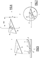
- FIG. 1A We have shown on the Figure 1A an eyeglass frame 1 which comprises two branches 2 and two oval-shaped frame circles 3 connected by a bridge 4. To this frame 1 is associated a mounting axis 5 parallel to the tangent 6 to the two circles 3 at the top of which this.
- Mount 1 is equipped with two demonstration glasses 7, transparent and non-corrective, the shape of which must be reproduced accurately from an optical glass blank to form a pair of glasses.
- Each glass 7 has two parallel spherical faces, namely a convex front face 8 and a concave rear face 9 ( figure 5 ), and bears on one of its faces a line 10 which extends along the axis of frame 5.
- the figure 2 schematically represents a blank of circular optical glass 14 to be converted by grinding into an optical glass fitting perfectly in the frame 1 chosen.
- the optical center CO of the blank is generally close to the center of its circular outline, and has been represented at this center on the figure 2 .
- the optician By means of a frontofocometer, the optician has positioned the optical axis AO of the lens according to the prescription. It has also marked and materialized on the lens, by means of a point CO placed at the optical center and two points 15, 16 located on either side of the point CO, an axis 17 passing through the point CO and parallel to the mounting axis 5, this axis 17 and the optical axis AO forming a prescribed angle ⁇ . Depending on the case, the angle ⁇ may be equal to zero or be positive as represented on the figure 2 .
- the figure 3 represents an acquisition and measurement device 18, which may in particular be as described in FIG. FR-A-2,854,268 supra.
- the device 18 comprises a support, in particular a transparent, flat and horizontal support plate 19 on which can be successively placed a presentation glass 7 and a blank 14.
- a plane projection screen 20 which may in particular be constituted by a frosted glass plate or a sheet of translucent material, of the tracing type.
- Means 21 for illuminating the analyzed object are disposed above the support plate 19, so as to illuminate the entire object 7 or 14 and to project a shadow of the object onto the screen of the object. projection 20, through the support plate 19.
- These lighting means 21 consist essentially of a light source 22, for example an LED, and an optical assembly or collimator 23, generally formed of a set of lenses. This set 23 is intended to channel the light radiation emitted by the source, and to provide a regular illumination of the object 7 or 14 with vertical light rays.
- the image of the object formed on the projection screen 20, this image being in fact the shadow of the object on this screen, is observed by a matrix video camera 24 connected to an image analysis and signal processing unit 25, itself connected to a monitor 26.
- This unit 25 is adapted to determine the dimensional characteristics of the patterns captured by the camera, in a manner known per se.
- the monitor 26 includes a display screen 27 and a keypad 28 for controlling and adjusting the display.
- the device further comprises programming means 29 connected on the one hand to the analysis and processing unit 25 and on the other hand to a control unit 30 of the grinder 31.
- the analysis and processing unit 25 may comprise image correction means to take into account the distortion of the pixels as a function of the distance to the vertical central axis XX of the camera 24 and the means of lighting 21.
- the acquisition and measurement device 118 shown in FIG. figure 4 does not differ from the device 18 of the figure 3 that by the reversal of the position of the lighting means 21 and the camera 24.
- the lighting means 21 are constituted by a plane and horizontal diffuser 32 disposed under the support 19, instead of the screen 20 of the figure 3 , while the camera 24 is disposed above the collimator 23, looking downward along the axis XX.
- the image of the object placed on the support 19 which is captured by the camera, and no longer its shadow on a screen as is the case with the device of the figure 3 .
- the glass Since the glass is spherical, it finds a position of stable equilibrium determined by its outline, in which the face 8 has a single point of contact 33 with the support 19.
- the glass 7 finds its equilibrium position when the center of gravity G of the glass is vertical to the point of contact 33.
- the outline of the glass and the centroid B, as well as the image 10I of the line 10 are determined and the image of the demonstration glass is positioned on the screen 27, with respect to an orthonormal reference X-X ', YY' of origin O ( figure 6 ), so that the center of gravity B coincides with the point O and the line 10I is parallel to the axis X-X '.
- the optician places on the screen the COI image of the optical center CO of the blank 14 in this orthonormal frame according to the position of the pupil of the wearer. To do this, for example, he can enter the pupillary half-distance (PD, distance between the two pupils, / 2) and the distance H between the pupil and the bottom of the frame in line with the pupil. .
- PD pupillary half-distance
- H distance between the pupil and the bottom of the frame in line with the pupil.
- the optician then lays the concave face of the blank 14 on the support 19.
- the image of the blank is integrated on the screen and superimposes the previously described information, namely the outline of the oriented presentation glass relative to the axis of the mount.
- the adapter 35 can finally be fixed, for example glued, on the convex upper face of the blank.
- the center of the adapter must be positioned to correspond to the point O, which itself corresponds to the center of gravity B of the 2D shape of the demonstration glass.
- the support axis of the adapter is then perfectly perpendicular to the surface of the screen, and its angular orientation is conventionally made parallel to the axis 10I.
- the device 18, 118 does not include a monitor 26.
- the data generated by the unit 25 is transferred to a separate device, called a "blocker", for fitting the adapter.
- the optical axis is respectively aligned with a generatrix of the cylinder or with the generatrices of radius R or r of a torus, defining the cylindrical or toric surface of the lens.
- the optical axis always passes in a plane containing the optical center of the lens, except where the lens has a cylindrical surface in combination with a flat surface.
- the position and the orientation of the optical axis of a lens is determined in a known manner by means of a frontofocometer.
Landscapes
- Engineering & Computer Science (AREA)
- Physics & Mathematics (AREA)
- General Physics & Mathematics (AREA)
- Chemical & Material Sciences (AREA)
- Mechanical Engineering (AREA)
- Inorganic Chemistry (AREA)
- Ceramic Engineering (AREA)
- Analytical Chemistry (AREA)
- Optics & Photonics (AREA)
- Ophthalmology & Optometry (AREA)
- Health & Medical Sciences (AREA)
- Geometry (AREA)
- Computer Vision & Pattern Recognition (AREA)
- Automation & Control Theory (AREA)
- Theoretical Computer Science (AREA)
- Eyeglasses (AREA)
- Grinding And Polishing Of Tertiary Curved Surfaces And Surfaces With Complex Shapes (AREA)
- Length Measuring Devices By Optical Means (AREA)
Claims (3)
- Verfahren zum Beschaffen und zum Messen von geometrischen Daten eines Demonstrationsglases (7), das auf ein Brillengestell (1) abgestimmt ist, wobei das Brillengestell (1) zwei Bügel (2) und zwei ovalförmige Brillenfassungen (3), die durch einen Steg (4) verbunden sind, umfasst, mit dem Ziel der Realisierung von Brillengläsern gleich diesem Demonstrationsglas, wobei eine Vorrichtung (18; 118) zum Beschaffen und zum Messen von geometrischen Daten verwendet wird, die umfasst:- einen transparenten Träger (19), der angepasst ist, ein ophtalmisches Objekt zu tragen;- von einer Seite des Trägers her Mittel (21) zum Beleuchten dieses Trägers;- von der anderen Seite des Trägers her eine Videokamera (24), die zu dem Träger gerichtet ist und optisch so angepasst ist, dass ein Videosignal erzeugt wird, das für mindestens ein dem ophtalmischen Objekt, das auf dem Träger liegt, zugeordnetes Motiv repräsentativ ist; und- Mittel (25) zur Signalanalyse und -verarbeitung, die am Eingang das von der Kamera erzeugte Videosignal empfangen,wobei das Verfahren dadurch gekennzeichnet ist, dass:(a) ein Demonstrationsglas (7) genommen wird, das eine Kontur, die an das Gestell (1) angepasst ist, und zwei parallele sphärische Flächen aufweist;(b) eine Achse (10) des Gestells auf das Demonstrationsglas gezeichnet wird, wobei die Achse (10) des Gestells parallel zu der Tangente (6) an die zwei Fassungen an deren Scheitelpunkte liegt;(c) die konvexe Fläche (8) des Demonstrationsglases (7) auf den transparenten Träger (19) der Vorrichtung (18) zum Beschaffen und zum Messen gelegt wird;(d) zwei dem Demonstrationsglas zugeordnete Motive, nämlich einerseits dessen Kontur und andererseits die Achse (10) des Gestells erfasst werden und die Abmessungen dieser zwei Motive bestimmt werden; und(e) die Position des Baryzentrums (B) der Kontur berechnet wird.
- Verfahren nach Anspruch 1, dadurch gekennzeichnet, dass die Vorrichtung zum Beschaffen und zum Messen einen einen Bildschirm (27) aufweisenden Monitor (26) umfasst, dass die Mittel (25) zur Signalanalyse und -verarbeitung angepasst sind, dem Monitor (26) ein Signal zu liefern, das repräsentativ für die zwei Motive ist, und diese zwei Motive auf dem Bildschirm (27) anzuzeigen, und dass auf dem Bildschirm auchdas Baryzentrum (B) angezeigt wird.
- Verfahren nach Anspruch 2, dadurch gekennzeichnet, dass:- die Position der Pupille des Trägers in Bezug auf das Demonstrationsglas erfasst wird;- diese Position auf dem Bildschirm (27) als Bild des optischen Zentrums (COI) angezeigt wird;- auf einen Rohling (14) des Brillenglases für ein mindestens eine zylindrische Fläche oder eine torische Fläche aufweisendes Glas, das optische Zentrum (CO) und die optische (AO) dieses Rohlings positioniert wird, gegebenenfalls unter Berücksichtigung einer Achsenkorrektur, die für den Träger verlangt wird;- auf den Rohling Punkte (15, CO, 16) gezeichnet werden, die eine Gerade (17) parallel zur Achse (10) des Gestells definieren;- die konkave Fläche des Rohlings (14) auf den Träger (19) positioniert wird, wobei das optische Zentrum (CO), das er trägt, und das Bild des optischen Zentrums (COI), das auf dem Bildschirm angezeigt wird, in Übereinstimmung gebracht wird, und die Gerade (17) ausgerichtet oder parallel mit dem Bild der Achse (10I) des Gestells, die auf dem Bildschirm (27) erscheint, positioniert wird; und- ein Adapter (35) auf die konvexe Fläche des Rohlings gelegt wird, wobei das Zentrum des Adapters mit dem Baryzentrum (B) übereinstimmend gemacht wird.
Applications Claiming Priority (1)
| Application Number | Priority Date | Filing Date | Title |
|---|---|---|---|
| FR1358971A FR3010802B1 (fr) | 2013-09-18 | 2013-09-18 | Procede d'acquisition et de mesure de donnees geometriques d'un verre de demonstration adapte a une monture de lunettes |
Publications (2)
| Publication Number | Publication Date |
|---|---|
| EP2851739A1 EP2851739A1 (de) | 2015-03-25 |
| EP2851739B1 true EP2851739B1 (de) | 2019-05-08 |
Family
ID=49510407
Family Applications (1)
| Application Number | Title | Priority Date | Filing Date |
|---|---|---|---|
| EP14183994.4A Active EP2851739B1 (de) | 2013-09-18 | 2014-09-08 | Verfahren zur Erfassung und Messung von geometrischen Daten eines Demonstrationsglases, das an ein Brillengestell angepasst ist |
Country Status (6)
| Country | Link |
|---|---|
| US (1) | US9644949B2 (de) |
| EP (1) | EP2851739B1 (de) |
| KR (1) | KR102235908B1 (de) |
| CN (1) | CN104460047B (de) |
| BR (1) | BR102014023171B1 (de) |
| FR (1) | FR3010802B1 (de) |
Families Citing this family (6)
| Publication number | Priority date | Publication date | Assignee | Title |
|---|---|---|---|---|
| US20160059373A1 (en) * | 2013-03-28 | 2016-03-03 | Hoya Corporation | Shape division method, shape division program and data processing device, and lens data processing method, lens edging method and lens data processing program |
| JP6063325B2 (ja) * | 2013-03-28 | 2017-01-18 | Hoya株式会社 | レンズ加工方法、レンズ加工プログラムおよび加工制御装置 |
| US10354403B2 (en) * | 2017-08-31 | 2019-07-16 | Albert Mo | Device for capturing images of eyewear from a forced perspective |
| CN113439009B (zh) * | 2019-03-15 | 2023-07-21 | 依视路国际公司 | 将粘性标签施加到眼科镜片面的方法以及实现该方法的设备 |
| US20240151988A1 (en) * | 2021-03-09 | 2024-05-09 | Essilor International | Method for automatically centering an ophthalmic lens |
| EP4402450A1 (de) * | 2021-09-16 | 2024-07-24 | Schneider GmbH & Co. KG | Verfahren und vorrichtung zur qualitätskontrolle von ophthalmischen linsen |
Family Cites Families (11)
| Publication number | Priority date | Publication date | Assignee | Title |
|---|---|---|---|---|
| US4330203A (en) * | 1979-10-15 | 1982-05-18 | Gerd Oppenheim | Optical lens layout and blocking device |
| DE3230495A1 (de) * | 1982-08-17 | 1984-02-23 | Wernicke & Co GmbH, 4000 Düsseldorf | Brillenglasrandschleifmaschine |
| US5428448A (en) * | 1993-10-20 | 1995-06-27 | Augen Wecken Plasticos S.R.L. De C.V. | Method and apparatus for non-contact digitazation of frames and lenses |
| US6012965A (en) * | 1997-10-07 | 2000-01-11 | Micro Optics Design Corp. | Manufacturing ophthalmic lenses using lens structure cognition and spatial positioning system |
| FR2854268B1 (fr) * | 2002-05-02 | 2005-12-02 | Briot Int | Dispositif d'acquisition et d'affichage de donnees associees a un objet ophtalmique et procede d'analyse d'image correspondant |
| FR2878979B1 (fr) * | 2004-12-03 | 2007-04-20 | Essilor Int | Procede et dispositif de mesure de puissance d'une lentille ophtalmique par mesure optique globale sans contact et palpage combines |
| EP2028533B1 (de) * | 2007-12-28 | 2020-09-23 | Essilor International | Verfahren zur Berechnung eines optischen Systems nach einer bestimmten Brillenfassung |
| FR2950161B1 (fr) * | 2009-09-14 | 2011-10-07 | Essilor Int | Procede d'elaboration d'une consigne de detourage d'une lentille ophtalmique en vue de son montage sur une monture de lunettes semi-cerclee. |
| FR2950160B1 (fr) * | 2009-09-14 | 2011-10-07 | Essilor Int | Methode d'elaboration d'une consigne de detourage d'une lentille ophtalmique. |
| US20110141535A1 (en) | 2009-12-14 | 2011-06-16 | Westcott Robert M | Document scanner with automatic dust avoidance |
| FR2959831B1 (fr) * | 2010-05-10 | 2013-02-15 | Essilor Int | Procede de preparation d'une lentille ophtalmique equipee d'une marque memoire. |
-
2013
- 2013-09-18 FR FR1358971A patent/FR3010802B1/fr not_active Expired - Fee Related
-
2014
- 2014-09-08 EP EP14183994.4A patent/EP2851739B1/de active Active
- 2014-09-10 US US14/482,377 patent/US9644949B2/en active Active
- 2014-09-18 KR KR1020140124345A patent/KR102235908B1/ko active Active
- 2014-09-18 CN CN201410479715.XA patent/CN104460047B/zh active Active
- 2014-09-18 BR BR102014023171-4A patent/BR102014023171B1/pt active IP Right Grant
Non-Patent Citations (1)
| Title |
|---|
| None * |
Also Published As
| Publication number | Publication date |
|---|---|
| CN104460047A (zh) | 2015-03-25 |
| CN104460047B (zh) | 2018-11-27 |
| BR102014023171A2 (pt) | 2015-12-15 |
| US9644949B2 (en) | 2017-05-09 |
| US20150077546A1 (en) | 2015-03-19 |
| BR102014023171B1 (pt) | 2020-12-15 |
| FR3010802B1 (fr) | 2015-10-16 |
| KR102235908B1 (ko) | 2021-04-06 |
| FR3010802A1 (fr) | 2015-03-20 |
| KR20150032505A (ko) | 2015-03-26 |
| EP2851739A1 (de) | 2015-03-25 |
Similar Documents
| Publication | Publication Date | Title |
|---|---|---|
| EP2851739B1 (de) | Verfahren zur Erfassung und Messung von geometrischen Daten eines Demonstrationsglases, das an ein Brillengestell angepasst ist | |
| EP0206860B1 (de) | Vorrichtung zum Zentrieren und Auflegen eines Adapters auf einen Rohling eines optischen Glases sowie zum Steuern einer Schleifmaschine | |
| EP1392472B1 (de) | Automatische oder halbautomatische maschine für das aussenkonturfräsen einer linse | |
| EP1692564B1 (de) | Einrichtung und verfahren zum automatischen erkennen verschiedener eigenschaften einer brillenlinse | |
| EP1722924A2 (de) | Vorrichtung zum zentrieren/festklemmen eines brillenglases, zugehörige verfahren zur manuellen zentrierung und verfahren zur automatischen erfassung | |
| EP1692563B1 (de) | Einrichtung zur automatischen erkennung der indexmarkierungen einer brillenlinse | |
| FR2465461A1 (fr) | Mensurateur optique de la position de l'axe visuel | |
| EP2091689B1 (de) | Vorrichtung zur bestimmung der position und/oder der querabmessung eines bohrlochs in einer linse zur herstellung von brillen mit randlosem rahmen | |
| WO2005092570A1 (fr) | Methode de centrage manuel d'une lentille ophtalmique dans un centreur-bloqueur et dispositif centreur-bloqueur associe | |
| FR2663528A3 (fr) | Procede pour la prise des mesures necessaires au montage des verres correcteurs et moyens pour sa mise en óoeuvre. | |
| EP3164759B1 (de) | Verfahren zum betrachten von markierungen auf einer brille | |
| FR2866442A1 (fr) | Afficheur orphtalmique comportant une lentille optalmique et un imageur optique | |
| EP1692565B1 (de) | Verfahren zur automatischen verifikation mindestens einer zentrierungseigenschaft einer mit indexmarkierungen ausgestatteten brillenlinse | |
| WO2000000924A1 (fr) | Procede et dispositif de lecture de reliefs portes par un recipient transparent ou translucide | |
| FR2939915A1 (fr) | Procede de preparation d'une lentille ophtalmique en vue de son montage sur une monture de lunettes cambree | |
| EP0021998B1 (de) | Apparat zum Feststellen des Durchmessers von Brillengläsern | |
| EP2866109B1 (de) | Verfahren und Vorrichtung zur Erfassung und Berechnung von Daten eines ophthalmischen Gegenstands | |
| FR2829842A1 (fr) | Dispositif d'acquisition des parametres de positionnement de verres ophtalmiques sur une monture de lunettes | |
| FR2763707A1 (fr) | Centrale de mesure en optique | |
| FR2854268A1 (fr) | Dispositif d'acquisition et d'affichage de donnees associees a un objet ophtalmique et procede d'analyse d'image correspondant | |
| FR3027385A1 (fr) | Dispositif d'acquisition et de mesure de donnees geometriques d'au moins un motif associe a un verre optique et procede associe | |
| WO2005092571A1 (fr) | Methode de centrage manuel d'une lentille ophtalmique de lunettes avec affichage intermittent d'un signe opaque servant à la correction de l'erreur de déviation prismatique induite par la lentille | |
| FR2858408A1 (fr) | Procede et machine de mesure de l'indice de refraction d'une lentille ophtalmique | |
| FR2872443A1 (fr) | Dispositif et procede de caracterisation d'une lentille optique | |
| FR2803048A1 (fr) | Procede pour faciliter le choix d'une monture de lunettes a la forme du visage de l'utilisateur |
Legal Events
| Date | Code | Title | Description |
|---|---|---|---|
| PUAI | Public reference made under article 153(3) epc to a published international application that has entered the european phase |
Free format text: ORIGINAL CODE: 0009012 |
|
| 17P | Request for examination filed |
Effective date: 20140908 |
|
| AK | Designated contracting states |
Kind code of ref document: A1 Designated state(s): AL AT BE BG CH CY CZ DE DK EE ES FI FR GB GR HR HU IE IS IT LI LT LU LV MC MK MT NL NO PL PT RO RS SE SI SK SM TR |
|
| AX | Request for extension of the european patent |
Extension state: BA ME |
|
| R17P | Request for examination filed (corrected) |
Effective date: 20150907 |
|
| RBV | Designated contracting states (corrected) |
Designated state(s): AL AT BE BG CH CY CZ DE DK EE ES FI FR GB GR HR HU IE IS IT LI LT LU LV MC MK MT NL NO PL PT RO RS SE SI SK SM TR |
|
| STAA | Information on the status of an ep patent application or granted ep patent |
Free format text: STATUS: EXAMINATION IS IN PROGRESS |
|
| 17Q | First examination report despatched |
Effective date: 20180703 |
|
| GRAP | Despatch of communication of intention to grant a patent |
Free format text: ORIGINAL CODE: EPIDOSNIGR1 |
|
| STAA | Information on the status of an ep patent application or granted ep patent |
Free format text: STATUS: GRANT OF PATENT IS INTENDED |
|
| RIC1 | Information provided on ipc code assigned before grant |
Ipc: G02C 13/00 20060101AFI20181105BHEP Ipc: B24B 49/12 20060101ALI20181105BHEP Ipc: B24B 9/14 20060101ALI20181105BHEP |
|
| INTG | Intention to grant announced |
Effective date: 20181129 |
|
| GRAS | Grant fee paid |
Free format text: ORIGINAL CODE: EPIDOSNIGR3 |
|
| GRAA | (expected) grant |
Free format text: ORIGINAL CODE: 0009210 |
|
| STAA | Information on the status of an ep patent application or granted ep patent |
Free format text: STATUS: THE PATENT HAS BEEN GRANTED |
|
| AK | Designated contracting states |
Kind code of ref document: B1 Designated state(s): AL AT BE BG CH CY CZ DE DK EE ES FI FR GB GR HR HU IE IS IT LI LT LU LV MC MK MT NL NO PL PT RO RS SE SI SK SM TR |
|
| REG | Reference to a national code |
Ref country code: GB Ref legal event code: FG4D Free format text: NOT ENGLISH |
|
| REG | Reference to a national code |
Ref country code: CH Ref legal event code: EP Ref country code: AT Ref legal event code: REF Ref document number: 1131107 Country of ref document: AT Kind code of ref document: T Effective date: 20190515 |
|
| REG | Reference to a national code |
Ref country code: DE Ref legal event code: R096 Ref document number: 602014046168 Country of ref document: DE Ref country code: IE Ref legal event code: FG4D Free format text: LANGUAGE OF EP DOCUMENT: FRENCH |
|
| REG | Reference to a national code |
Ref country code: NL Ref legal event code: MP Effective date: 20190508 |
|
| REG | Reference to a national code |
Ref country code: LT Ref legal event code: MG4D |
|
| PG25 | Lapsed in a contracting state [announced via postgrant information from national office to epo] |
Ref country code: SE Free format text: LAPSE BECAUSE OF FAILURE TO SUBMIT A TRANSLATION OF THE DESCRIPTION OR TO PAY THE FEE WITHIN THE PRESCRIBED TIME-LIMIT Effective date: 20190508 Ref country code: NL Free format text: LAPSE BECAUSE OF FAILURE TO SUBMIT A TRANSLATION OF THE DESCRIPTION OR TO PAY THE FEE WITHIN THE PRESCRIBED TIME-LIMIT Effective date: 20190508 Ref country code: LT Free format text: LAPSE BECAUSE OF FAILURE TO SUBMIT A TRANSLATION OF THE DESCRIPTION OR TO PAY THE FEE WITHIN THE PRESCRIBED TIME-LIMIT Effective date: 20190508 Ref country code: ES Free format text: LAPSE BECAUSE OF FAILURE TO SUBMIT A TRANSLATION OF THE DESCRIPTION OR TO PAY THE FEE WITHIN THE PRESCRIBED TIME-LIMIT Effective date: 20190508 Ref country code: FI Free format text: LAPSE BECAUSE OF FAILURE TO SUBMIT A TRANSLATION OF THE DESCRIPTION OR TO PAY THE FEE WITHIN THE PRESCRIBED TIME-LIMIT Effective date: 20190508 Ref country code: AL Free format text: LAPSE BECAUSE OF FAILURE TO SUBMIT A TRANSLATION OF THE DESCRIPTION OR TO PAY THE FEE WITHIN THE PRESCRIBED TIME-LIMIT Effective date: 20190508 Ref country code: HR Free format text: LAPSE BECAUSE OF FAILURE TO SUBMIT A TRANSLATION OF THE DESCRIPTION OR TO PAY THE FEE WITHIN THE PRESCRIBED TIME-LIMIT Effective date: 20190508 Ref country code: PT Free format text: LAPSE BECAUSE OF FAILURE TO SUBMIT A TRANSLATION OF THE DESCRIPTION OR TO PAY THE FEE WITHIN THE PRESCRIBED TIME-LIMIT Effective date: 20190908 Ref country code: NO Free format text: LAPSE BECAUSE OF FAILURE TO SUBMIT A TRANSLATION OF THE DESCRIPTION OR TO PAY THE FEE WITHIN THE PRESCRIBED TIME-LIMIT Effective date: 20190808 |
|
| PG25 | Lapsed in a contracting state [announced via postgrant information from national office to epo] |
Ref country code: GR Free format text: LAPSE BECAUSE OF FAILURE TO SUBMIT A TRANSLATION OF THE DESCRIPTION OR TO PAY THE FEE WITHIN THE PRESCRIBED TIME-LIMIT Effective date: 20190809 Ref country code: LV Free format text: LAPSE BECAUSE OF FAILURE TO SUBMIT A TRANSLATION OF THE DESCRIPTION OR TO PAY THE FEE WITHIN THE PRESCRIBED TIME-LIMIT Effective date: 20190508 Ref country code: RS Free format text: LAPSE BECAUSE OF FAILURE TO SUBMIT A TRANSLATION OF THE DESCRIPTION OR TO PAY THE FEE WITHIN THE PRESCRIBED TIME-LIMIT Effective date: 20190508 Ref country code: BG Free format text: LAPSE BECAUSE OF FAILURE TO SUBMIT A TRANSLATION OF THE DESCRIPTION OR TO PAY THE FEE WITHIN THE PRESCRIBED TIME-LIMIT Effective date: 20190808 |
|
| REG | Reference to a national code |
Ref country code: AT Ref legal event code: MK05 Ref document number: 1131107 Country of ref document: AT Kind code of ref document: T Effective date: 20190508 |
|
| PG25 | Lapsed in a contracting state [announced via postgrant information from national office to epo] |
Ref country code: DK Free format text: LAPSE BECAUSE OF FAILURE TO SUBMIT A TRANSLATION OF THE DESCRIPTION OR TO PAY THE FEE WITHIN THE PRESCRIBED TIME-LIMIT Effective date: 20190508 Ref country code: AT Free format text: LAPSE BECAUSE OF FAILURE TO SUBMIT A TRANSLATION OF THE DESCRIPTION OR TO PAY THE FEE WITHIN THE PRESCRIBED TIME-LIMIT Effective date: 20190508 Ref country code: EE Free format text: LAPSE BECAUSE OF FAILURE TO SUBMIT A TRANSLATION OF THE DESCRIPTION OR TO PAY THE FEE WITHIN THE PRESCRIBED TIME-LIMIT Effective date: 20190508 Ref country code: RO Free format text: LAPSE BECAUSE OF FAILURE TO SUBMIT A TRANSLATION OF THE DESCRIPTION OR TO PAY THE FEE WITHIN THE PRESCRIBED TIME-LIMIT Effective date: 20190508 Ref country code: CZ Free format text: LAPSE BECAUSE OF FAILURE TO SUBMIT A TRANSLATION OF THE DESCRIPTION OR TO PAY THE FEE WITHIN THE PRESCRIBED TIME-LIMIT Effective date: 20190508 Ref country code: SK Free format text: LAPSE BECAUSE OF FAILURE TO SUBMIT A TRANSLATION OF THE DESCRIPTION OR TO PAY THE FEE WITHIN THE PRESCRIBED TIME-LIMIT Effective date: 20190508 |
|
| REG | Reference to a national code |
Ref country code: DE Ref legal event code: R097 Ref document number: 602014046168 Country of ref document: DE |
|
| PG25 | Lapsed in a contracting state [announced via postgrant information from national office to epo] |
Ref country code: SM Free format text: LAPSE BECAUSE OF FAILURE TO SUBMIT A TRANSLATION OF THE DESCRIPTION OR TO PAY THE FEE WITHIN THE PRESCRIBED TIME-LIMIT Effective date: 20190508 |
|
| PLBE | No opposition filed within time limit |
Free format text: ORIGINAL CODE: 0009261 |
|
| STAA | Information on the status of an ep patent application or granted ep patent |
Free format text: STATUS: NO OPPOSITION FILED WITHIN TIME LIMIT |
|
| PG25 | Lapsed in a contracting state [announced via postgrant information from national office to epo] |
Ref country code: TR Free format text: LAPSE BECAUSE OF FAILURE TO SUBMIT A TRANSLATION OF THE DESCRIPTION OR TO PAY THE FEE WITHIN THE PRESCRIBED TIME-LIMIT Effective date: 20190508 |
|
| 26N | No opposition filed |
Effective date: 20200211 |
|
| PG25 | Lapsed in a contracting state [announced via postgrant information from national office to epo] |
Ref country code: PL Free format text: LAPSE BECAUSE OF FAILURE TO SUBMIT A TRANSLATION OF THE DESCRIPTION OR TO PAY THE FEE WITHIN THE PRESCRIBED TIME-LIMIT Effective date: 20190508 |
|
| PG25 | Lapsed in a contracting state [announced via postgrant information from national office to epo] |
Ref country code: MC Free format text: LAPSE BECAUSE OF FAILURE TO SUBMIT A TRANSLATION OF THE DESCRIPTION OR TO PAY THE FEE WITHIN THE PRESCRIBED TIME-LIMIT Effective date: 20190508 Ref country code: SI Free format text: LAPSE BECAUSE OF FAILURE TO SUBMIT A TRANSLATION OF THE DESCRIPTION OR TO PAY THE FEE WITHIN THE PRESCRIBED TIME-LIMIT Effective date: 20190508 |
|
| REG | Reference to a national code |
Ref country code: CH Ref legal event code: PL |
|
| PG25 | Lapsed in a contracting state [announced via postgrant information from national office to epo] |
Ref country code: LU Free format text: LAPSE BECAUSE OF NON-PAYMENT OF DUE FEES Effective date: 20190908 Ref country code: LI Free format text: LAPSE BECAUSE OF NON-PAYMENT OF DUE FEES Effective date: 20190930 Ref country code: CH Free format text: LAPSE BECAUSE OF NON-PAYMENT OF DUE FEES Effective date: 20190930 Ref country code: IE Free format text: LAPSE BECAUSE OF NON-PAYMENT OF DUE FEES Effective date: 20190908 |
|
| REG | Reference to a national code |
Ref country code: BE Ref legal event code: MM Effective date: 20190930 |
|
| PG25 | Lapsed in a contracting state [announced via postgrant information from national office to epo] |
Ref country code: BE Free format text: LAPSE BECAUSE OF NON-PAYMENT OF DUE FEES Effective date: 20190930 |
|
| GBPC | Gb: european patent ceased through non-payment of renewal fee |
Effective date: 20190908 |
|
| PG25 | Lapsed in a contracting state [announced via postgrant information from national office to epo] |
Ref country code: GB Free format text: LAPSE BECAUSE OF NON-PAYMENT OF DUE FEES Effective date: 20190908 |
|
| PG25 | Lapsed in a contracting state [announced via postgrant information from national office to epo] |
Ref country code: CY Free format text: LAPSE BECAUSE OF FAILURE TO SUBMIT A TRANSLATION OF THE DESCRIPTION OR TO PAY THE FEE WITHIN THE PRESCRIBED TIME-LIMIT Effective date: 20190508 |
|
| PG25 | Lapsed in a contracting state [announced via postgrant information from national office to epo] |
Ref country code: IS Free format text: LAPSE BECAUSE OF FAILURE TO SUBMIT A TRANSLATION OF THE DESCRIPTION OR TO PAY THE FEE WITHIN THE PRESCRIBED TIME-LIMIT Effective date: 20190908 |
|
| PG25 | Lapsed in a contracting state [announced via postgrant information from national office to epo] |
Ref country code: HU Free format text: LAPSE BECAUSE OF FAILURE TO SUBMIT A TRANSLATION OF THE DESCRIPTION OR TO PAY THE FEE WITHIN THE PRESCRIBED TIME-LIMIT; INVALID AB INITIO Effective date: 20140908 Ref country code: MT Free format text: LAPSE BECAUSE OF FAILURE TO SUBMIT A TRANSLATION OF THE DESCRIPTION OR TO PAY THE FEE WITHIN THE PRESCRIBED TIME-LIMIT Effective date: 20190508 |
|
| PG25 | Lapsed in a contracting state [announced via postgrant information from national office to epo] |
Ref country code: MK Free format text: LAPSE BECAUSE OF FAILURE TO SUBMIT A TRANSLATION OF THE DESCRIPTION OR TO PAY THE FEE WITHIN THE PRESCRIBED TIME-LIMIT Effective date: 20190508 |
|
| P01 | Opt-out of the competence of the unified patent court (upc) registered |
Effective date: 20230512 |
|
| PGFP | Annual fee paid to national office [announced via postgrant information from national office to epo] |
Ref country code: DE Payment date: 20250919 Year of fee payment: 12 |
|
| PGFP | Annual fee paid to national office [announced via postgrant information from national office to epo] |
Ref country code: FR Payment date: 20250922 Year of fee payment: 12 |
|
| PGFP | Annual fee paid to national office [announced via postgrant information from national office to epo] |
Ref country code: IT Payment date: 20250930 Year of fee payment: 12 |