EP2852017A2 - Installation socket for electro-technical purposes - Google Patents
Installation socket for electro-technical purposes Download PDFInfo
- Publication number
- EP2852017A2 EP2852017A2 EP14401087.3A EP14401087A EP2852017A2 EP 2852017 A2 EP2852017 A2 EP 2852017A2 EP 14401087 A EP14401087 A EP 14401087A EP 2852017 A2 EP2852017 A2 EP 2852017A2
- Authority
- EP
- European Patent Office
- Prior art keywords
- installation
- subframe
- adapter
- installation box
- mouth
- Prior art date
- Legal status (The legal status is an assumption and is not a legal conclusion. Google has not performed a legal analysis and makes no representation as to the accuracy of the status listed.)
- Granted
Links
Images



Classifications
-
- H—ELECTRICITY
- H02—GENERATION; CONVERSION OR DISTRIBUTION OF ELECTRIC POWER
- H02G—INSTALLATION OF ELECTRIC CABLES OR LINES, OR OF COMBINED OPTICAL AND ELECTRIC CABLES OR LINES
- H02G3/00—Installations of electric cables or lines or protective tubing therefor in or on buildings, equivalent structures or vehicles
- H02G3/02—Details
- H02G3/08—Distribution boxes; Connection or junction boxes
- H02G3/12—Distribution boxes; Connection or junction boxes for flush mounting
- H02G3/121—Distribution boxes; Connection or junction boxes for flush mounting in plain walls
Definitions
- the invention relates to an installation box for electrical purposes for installation in a wall with a mouth side open can body.
- Installation boxes of this type are widely known in the art.
- the state of the art for example, on the AT 233645 B directed.
- Installation boxes are known in different embodiments in the prior art.
- such installation boxes are designed as flush-mounted installation boxes, as described in the cited document.
- installation boxes are known, which are described as hollow wall boxes and which are intended for installation in a mounting hole of a cavity wall.
- the corresponding wall has an installation space for an installation box.
- a corresponding blind hole can be formed in the wall or, in the case of hollow wall boxes, a cavity can be formed in the cavity wall Cut out section whose cross section corresponds to the cross section of the installation box so that the installation box can be inserted into the cutout.
- the corresponding wall is provided with installed installation box with a plaster layer, so that the installation box behind the outer surface with its mouth, which is formed by the plaster layer.
- support rings are known, which are combined with a corresponding switch, button, a socket or the like.
- This installation unit is then inserted into the installation box, so that the support ring rests on the outside on the mouth edge of the installation box and / or the plaster layer, which protrudes from the mouth of the installation box.
- the securing position of the installation device in the installation box for example, by the fact that spreader claws are arranged on the support ring, which can be tightened by means of accessible from the front of the support ring ago screws, so that the spreader claws are tightened against the jacket of the installation box and thus a secure fit of the installation device in the installation box is reached.
- the support ring To attach the support ring to the mouth of the installation box to be able to, it is also known that the support ring has keyhole-like recesses, which are penetrated by fastening screws which are screwed into the installation device. Finally, a cover plate is applied to such an arrangement and secured in a suitable manner on the installation device or on the support ring.
- the present invention seeks to provide an installation box generic type, which allows a nearly flush arrangement of a cover plate in a corresponding installation box, with a supernatant is avoided by a support ring or other parts of the installation device.
- the invention proposes that the subframe in the can body in the direction of a bottom of the can body and in the direction of the mouth of the can body is adjustable and lockable in different positions, the recording and support for a built-in can body installation device and / or a support ring for it.
- Such a configuration makes it possible that the relative mounting depth of the subframe to the can body of the installation box is variable, so that the installation depth can be adapted to the local present desired state.
- the adjustment of the mounting depth of the subframe relative to the can body can be realized for example by a threaded adjustment of the parts to each other or by latching the parts in different positions.
- the subframe together with its associated parts can be further moved to the outer surface formed by the wall.
- thinner plaster layers it is possible to lower the subframe deeper in the can body.
- a mounting situation is achieved in which neither components of the subframe nor the attached elements with the exception of a possibly existing cover plate or the like protrude over the plane spanned by the wall level.
- the can body may have any cross-section, for example polygonal, in particular square, wherein the subframe is preferably adapted to the cross-sectional shape.
- the can body has a circular cross-section.
- the can body is formed cylindrically with circumferential mantle.
- Installation boxes with a circular cross-section and also with a cylindrical jacket are known in the art.
- Such installation boxes are a model for the installation box inventive type, wherein the installation box according to the invention is larger in diameter than conventional installation boxes, so that in the installation box according to the invention, the subframe, the electrical installation equipment and the support ring can be placed sunk.
- the can body has muzzle side transversely to its longitudinal extension outwardly projecting mating surfaces which rest in installation target position on the wall outside next to the mounting hole.
- the can body on the outlet side circumferentially outside as a counter bearing surface has a collar or flange.
- Such configurations serve to be able to use the installation box in a simple manner in a wall opening, wherein the abutment surfaces or the circumferential collar form a Einstecktiefenbegrenzung for the installation box.
- the collar and the abutment surfaces are provided in the mouth area of the installation box, so that the installation box does not protrude beyond the flange or on the abutment surfaces to the outside. After applying a plaster layer or the like on the wall surface, the counter bearing surfaces are covered by this.
- the subframe is designed as a ring body, projects from the at the mouth of the can body end facing a collar transversely outwards.
- the ring body has a sufficient height, as it corresponds to its purpose.
- the provided at one end of the annular body collar is advantageous in the arrangement of the fastening means for the individual elements, in particular the means by means of which the subframe is held adjustably in the can body.
- adjusting means are held on the subframe, which are engaged with Stellstofffactn on the inner surface of the can body and by means of which the adjustment and detection is realized in different positions.
- the adjusting means are cap screws whose head is held rotatably in a cage formed on the outer casing of the subframe, but axially immovable and whose threaded shaft is screwed into a channel forming the Stellstofffact on the inner surface of the can body.
- the arrangement of the adjusting means is preferably provided on the outer casing of the subframe, wherein for access to the actuating means of the collar projecting radially beyond the actuating means, in the area but the adjusting means has recesses, which areteurgreifbar example with a tool.
- adjusting means receptacles are formed in the region of the subframe arranged adjusting means, in which engage the actuating means in the desired position and by means of which the adjustment of the subframe is possible in different positions relative to the installation box.
- the adjusting means head screws whose head is rotatably supported in each case in a formed on the outer casing of the subframe cage, but axially immovable, so that the screwing of the threaded shaft into the channel on the inner shell of the installation box is variable by rotation of the cap screws.
- the cap screw and corresponding thread-related screwing or unscrewing from the installation box of the subframe is moved and adjusted to the appropriate level.
- the subframe on the inner casing channels which are aligned parallel to a central longitudinal axis of the subframe has, and that retaining means, in particular cap screws are screwed or screwed into this, by means of which an installation device or a support ring, the installation device holds, is attached to the subframe or fastened.
- the can body is formed as a hollow wall box, on the jacket are arranged on and swing-out tabs which are actuated by means inserted in channels of the can body strap bolts and adjustable in the swung position along the jacket in the direction of the mouth.
- At least one protruding web is arranged on the subframe on its side facing the mouth parallel to the direction of adjustment.
- the installer who installed the installation box together with subframe and the like easily recognize and adjust the depth of the subframe relative to the outer wall surface, namely in the namely the projecting webs on adjustment of the subframe relative to the installation box then indicate the desired installation depth, if the free web ends in the of the wall or the lie thereon plaster layer spanned reference plane.
- preferably several equal length webs are provided, for example, 3 or 4 evenly distributed over the circumference of the subframe.
- subframe is designed as a mouth-open can body.
- the subframe is designed as an open ring body.
- the subframe could also be designed as an open can body, which is intended and adapted to accommodate appropriate installation equipment.
- predetermined breaking points, cutouts or the like which are used for cable entry and removal, are also provided in the form of an open can body subframe so that corresponding cable connections and the like in the interior of the open Can body can be performed.
- an open annular subframe there is an opening for feeding cables or the like anyway.
- the abutment surface in the form of the circumferential mouth edge together opposite areas or at least at one edge region has predetermined breaking points at which the mouth edge for generating a tangentially directed or formed as a secant flat peripheral edge is breakable.
- This configuration serves to allow a close system of installation boxes installed side by side, which have a circular cross-section per se.
- the flattening makes it possible to bring the adjacent cans together with the surface created by the flattening, so that the standard installation distance can be achieved.
- the corresponding support ring is designed in terms of its design and geometric configurations so that it can be inserted without constraint in the installation box.
- the can body is covered in the installation target position of a cover plate, are integrated in the electrical switching elements or the passages for switches, push-button, sockets or the like parts of electrical installation equipment, wherein the cover plate is preferably releasably attached to the support ring or to a built-in installation device, for example by means of detents or screws.
- the invention relates to an installation box for electrical purposes for installation in a wall with a can body with an open at the front or opening opening for installation parts.
- installation boxes are circular in cross-section, since a corresponding opening in a wall for use of such a box or a hole in a cavity wall for installation of such a can most easily be generated in a circular shape.
- different cross-sectional shapes of the installation boxes are possible. These may well be formed polygonal or in a circular configuration with flattened Be configured opposite side surfaces.
- Another type of installation box is a so-called concrete building box, which is embedded in precast concrete elements.
- Such concrete building blocks are independent of their cross-section of the installation, as they are usually nailed to the formwork of concrete formwork and covered by reinforcing material. The potting then takes place with concrete mass. It is completely indifferent, which cross-sectional shape has such an installation box.
- Typical of such installation boxes, which are suitable and intended for installation as concrete building blocks is that they are closed on all sides, so contrary to the hollow wall box and the flush box have no open mouth, but the mouth is closed by a lid or a closure part. After concreting and stripping the corresponding concrete part of this cover or the like is free and can be cut out by means of a suitable tool, so that then the installation space of the concrete wall box for the installation of installation parts is available.
- the corresponding wall After installation of such installation boxes in corresponding wall openings, it is common that the corresponding wall, regardless of which type is used, is provided with installed installation box with a plaster layer on which, if necessary, cover layers are applied. Thus lies the Installation box with its mouth behind the outer surface formed by the plaster layer or the like.
- support rings are known, which are combined with a corresponding switch, button, a socket or the like.
- Such a mounting unit can then be inserted into the mouth of the installation box, so that the support ring rests on the outside of the mouth edge of the installation box and / or on the plaster layer, which protrudes from the mouth of the installation box.
- the securing position of the installation device in the installation box is usually characterized in that the support ring Sp Dr Drllen are arranged, which can be tightened by means of accessible from the front of the support ring forth screws, so that the Sp Drllen be tightened against the jacket of the installation box and thus a secure fit of the installation device in the installation box is reached.
- the support ring has keyhole-like recesses, which are penetrated by fastening screws which are screwed into the installation device.
- a cover plate can be applied to such an arrangement and suitably on Installation device or attached to the support ring.
- the present invention seeks to provide installation boxes generic type, which allows a nearly flush arrangement of a cover at a corresponding installation box in the installed state, with a supernatant is avoided by a support ring or other parts of the installation device.
- these installations should be possible regardless of the thickness of the plaster layer or the like, which is applied to a corresponding wall surface after installation of the installation box.
- a first solution to this problem proposes according to the invention that on the can body a the front of which superior adapter is attached and that in the adapter, a subframe relative to the adapter in the direction of the front of the can body and away from this is arranged adjustable, which forms an installation equipment carrier for built-in or installable in the can body installation equipment or holds a support ring for it.
- a protruding adapter is attached to the can body on its front side, which has the installation opening.
- the adapter may for example have a circular recess which is adapted to the preferably circular opening of the installation box.
- the outer dimension of the adapter may be annular or polygonal.
- Such an adapter is connected with suitable measures firmly to the can body, so that these two parts form a mounting unit. In the case of a flush-mounted box, this unit can be installed in the corresponding recess of the wall or the like, wherein in the installation situation the edge of the adapter facing away from the can body is arranged flush in the wall surface.
- the corresponding adapter can be fixed to the corresponding installation box before concreting. But it is also possible to put the adapter after pouring the installation box with concrete and after removing the formwork and with the To connect can body. Again, the edge facing away from the can body is then substantially flush in the wall surface of the concrete part.
- a subframe is used, which lies in an end position flush behind the peripheral edge of the adapter or terminates with this, which faces away from the can body.
- This subframe is adjustable with respect to the adapter in such a way that it can also be adjusted to a position in which it is adjustable relative to the adapter towards the outside, that is to say in the direction of the opening of the wall surface.
- the subframe relative to the adapter can be adjusted and adjusted accordingly, so that the subframe as a mounting element for installation equipment or support rings still sufficiently behind the plane spanned by the plaster level, but against the previous adapter is relocated.
- This ensures that the built-in installation box and content Erten on the subframe elements are vorverlagert as necessary, but lie behind the mounting plane formed by the plaster layer or the like or at most lie in this plane. This makes it possible to realize a nearly flush installation of an applied to the installation box cover plate, trim or the like.
- a second solution of the problem is characterized in that an adapter is arranged, which is intended for installation in an opening of a cavity wall and means for attachment in the opening, that the can body is inserted into the adapter, wherein the can body front side has an auxiliary frame which is firmly connected or connected to the can body, and that the can body including subframe relative to the adapter in the adapter and from the adapter is adjustably arranged, wherein the subframe forms an installation equipment carrier built into the can body or installable installation equipment or holds a support ring for it ,
- an adapter is provided, which is inserted into the opening of a hollow wall and is fixed by means of suitable fastening means in this position on the cavity wall.
- the can body which may be a conventional hollow wall box, is then inserted into the adapter ring, wherein the can body front side has the subframe, which is fixedly connected to the can body.
- the can body thus forms a unit with the subframe.
- This unit is adjustable with respect to the permanently installed adapter, that is adjustable into the adapter or out of the adapter, so that an adaptation to the installation situation with respect to the level of the wall surface, which is equipped with a plaster surface is achieved.
- the subframe forms an installation equipment carrier for built-in or installable in the can body installation equipment or a support ring for it.
- the particular advantage of the embodiment of the invention is that previously common installation boxes of different types are used without further changes, ie usual cavity wall boxes, common wall outlets and conventional concrete wall boxes, these only with the corresponding adapter or with the additional subframe can be combined.
- the subframe can be identical for all solutions. Only the adapter distinguishes an embodiment which is suitable for flush-mounted boxes and concrete building boxes, and a second embodiment which is suitable and intended for cavity wall boxes.
- the subframe is held relative to the adapter towards a bottom edge of the adapter and towards the mouth of the wall opening adjustable and lockable in different positions.
- the relative mounting depth of the subframe is variable relative to the adapter, so that the mounting depth can be adapted to the local present desired state.
- the adjustment of the mounting depth of the subframe relative to the adapter for example, by a threaded adjustment of the parts to each other or by Rastung the parts can be realized in different positions.
- the subframe together with its associated parts can be further moved to the outer surface formed by the wall.
- the subframe For thinner plaster layers, it is possible to lower the subframe deeper in the adapter.
- a mounting situation is adjustable, in which neither components of the subframe nor the elements attached thereto with the exception of a possibly existing cover plate or the like project beyond the plane spanned by the plastered wall level.
- the cross-sectional shape of the can body and also the cross-sectional shape of the adapter and the subframe may be arbitrary, for example polygonal, in particular square or circular, with only the interaction of the parts must be ensured together.
- the adapter which is intended for installation in an opening of a cavity wall and having the corresponding means for attachment in the opening, may be formed as an open ring. But it is also possible to provide the adapter with a circumferential thin wall and a bottom in the same configuration, in particular an airtight arrangement in one Cavity wall opening to achieve.
- the thin wall can be a skin or foil.
- the adapter is preferably designed as an open ring.
- the adapter has a transversely directed to the longitudinal extent of the can body edge region and one of the outside edge opposite the front of the can body protruding collar or collar parts and that the subframe has a parallel to this edge region and collar flange edge and collar or collar parts ,
- This shaping of the adapter is conducive with respect to the installation of the adapter in the corresponding wall opening or in the corresponding concrete component, wherein in addition a correspondingly fitting receptacle for the subframe is formed by the edge region and the collar projecting therefrom.
- the subframe can be applied in a mounting position with its flange edge to the edge region of the adapter and is aligned with its collar parallel to the collar of the adapter.
- At the edge region of the adapter directed from the front side actuating means shots are formed for adjusting means or screws in the parts of the actuating means or the threaded shaft of Engage or engage screws that are arranged on the subframe axially immovable, but rotatable.
- the adjusting means are designed as cap screws whose head is rotatably held in a trained on the outer casing of the subframe cage, but axially immovable, and the threaded shaft can be screwed into a Stellstofffact forming channel, for example on the outer jacket of the adapter ,
- the arrangement of the adjusting means is preferably provided on the jacket of the subframe, wherein for accessing the adjusting means whose flange edge projects radially beyond the adjusting means, but in the region of the adjusting means has recesses which are tangible with a tool.
- the adjusting means which are preferably designed as cap screws, are arranged so that the head is rotatably held in a cage formed on the outer casing of the subframe, but axially immovable, so by turning the capscrews the screwing of the threaded shaft into the channel on the adapter, the forms the Stellstofffact, is variable. Turning the capscrew and threading or unscrewing the subframe from the adapter or adapter will cause the subframe to turn forcibly moved and adjusted to the appropriate level.
- the can body has at the front at an orifice a radially outwardly projecting flanged edge or flanged edge portions.
- installation boxes of the flange is a positioning aid for the can body in the adapter, wherein the adapter forms a corresponding receiving edge, is applied to the assembly in the desired position of the flange of the can body.
- the adapter has a frontally projecting radially outward flange edge or flange edge parts.
- the adapter on and swing-out tabs are arranged, which are actuated by means of adapter held tab bolts and adjustable in the pivoted position parallel to the central axis of the adapter.
- the adapter is fastened in a simple manner to the cutout of the cavity wall, as is customary in the attachment of hollow wall boxes.
- projecting webs are formed parallel to the actuating direction on the subframe, which protrude with respect to the subframe and / or are formed by projecting from an edge region of the subframe collar parts.
- the installer who installed the installation box including adapter and subframe can easily recognize and adjust the installation depth of the subframe relative to the outer wall surface, namely in the protruding webs upon adjustment of the subframe in the installation target position relative to the adapter then indicate the desired installation depth when the free web ends lie in the plane defined by the wall or the plaster layer located thereon reference plane.
- the webs may have a length corresponding to the desired depth of the subframe so that installation elements can be mounted, which are then behind the reference plane.
- the webs can be cut to the desired length, for example, so that they protrude for example 6 mm or 8 mm.
- an inner dimension or inner diameter adapted support ring can be used in the subframe, which then rests on the subframe and is dominated by the webs.
- the can body together with adapter and subframe in the installation target position is covered by a cover plate, which is preferably supported on the protruding webs of the subframe and are integrated in the electrical switching elements or the switches, key switches, sockets or other parts of electrical Installation devices, wherein the cover plate is preferably releasably attached to a built-in the can body support ring or on a built-in installation device, preferably by means of screws or locking means.
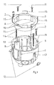
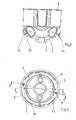
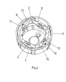
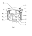
- an installation box for electrical purposes for installation in an opening of a wall with a mouth side open can body 1 is shown.
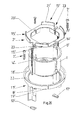
- a subframe 2 is inserted into the can body 1, which forms the receptacle and holder for a can be installed in the can body 1 installation device and / or a support ring 3 for an installation device.
- the subframe 2 is aligned with its directed to the mouth of the can body 1 end portion in the installation target position so that it lies behind the mouth level of the can body 1, as shown in the drawing figures.
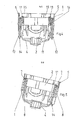
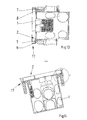
- the subframe 2 is held in the can body 1 in the direction of a bottom 4 of the can body 1 or in the direction of the mouth of the can body 1 adjustable and lockable in different positions, in particular in FIG. 8 and 9 is illustrated.
- the can body 1 of the installation box has a circular cross-section, wherein the can body is formed cylindrically with circumferential mantle.
- the can body 1 On the mouth side, the can body 1 has transverse to its longitudinal extension directed, outwardly projecting abutment surfaces 5, which are preferably formed as a mouth side circumferential collar, as shown in the figures.
- the jacket of the can body 1 and / or the bottom 4 may have breakable or pierceable areas, which serve for the insertion and removal of cables or installation tubes.
- the subframe 2 is designed as a ring body, protrudes from the at the mouth of the can body 1 zugenden end portion a collar 6 transversely outwards.
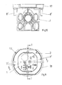
- actuating means 7 are held, which are engaged with adjusting means 8 on the inner surface of the can body 1 and by means of which the adjustment and detection is realized in different positions.
- the adjusting means are 7 cap screws, which are rotatably but axially held immovable. Their threaded shank is in each case screwed into a channel of Stellstofffact 8 on the inner shell of the installation box.
- the screws or adjusting means 7 each take with the subframe 2, so that it is adjusted relative to the can body.
- the head of the cap screws in each case in a formed on the outer casing of the subframe 2 cage 9 can be rotatably held but axially immovable.
- the installation box is designed as a hollow wall box, on the jacket on and swing-out tabs 12 are arranged, which are actuated by means inserted into channels 13 of the can body 1 tab bolts 14, ie from the pivoted-back position, in which they are behind the circumference of the can jacket , Are movable in a swung-out fastening position and are adjustable in the pivoted position along the jacket in the direction of its mouth.
- protruding webs 15 are additionally formed on its side facing the mouth side parallel to the actuating direction, which form an assembly aid for the installer, so that it can visually recognize the correct distance of the subframe 2 from the outer surface of the wall into which the installation box is inserted ,
- the can body 1 has in the region of its circumferential abutment surface 5 to each other opposite areas or at least one region of predetermined breaking points 16 at which the mouth edge for generating a tangentially directed or formed as a secant flat edge edge is breakable. This serves to achieve the standard installation distance of juxtaposed installation boxes.
- FIGS. 6 to 8 is in the installation box or the can body 1 whose inner dimension or inner diameter adapted support ring 3 is used, which rests on the mouth of the subframe 2, in particular its collar 6.
- the support ring 3 may be connected in a conventional manner with an installation device, such as a switch, push-button, a socket or other electrical installation equipment.
- an installation device such as a switch, push-button, a socket or other electrical installation equipment.
- the invention makes it possible in a simple manner to align the installed in the can body 1 of the installation box elements by means of the subframe 2 at the desired height so that subsequently a supernatant arrangement relative to the outer surface of the mounting wall is achieved, so that a fixed on this unit cover or aperture in Essentially flush with the surface of the mounting wall.
- the cover or panel may have openings for switches, plugs or the like. she can also be designed as a sensor surface or sensors can be embedded in it.
- the a can body 1 with an open at the front or opening opening for installation parts.
- it is a can body 1, which is designed in the form of a conventional flush-mounted box.
- FIG. 19 it is a can body 1, which is designed in the manner of a conventional concrete building box.
- the can body 1 is initially closed by a detachable wall at its mouth. This in the FIG. 19
- the above apparent wall can be in the installation situation, if the part is thus cast in a concrete part, with a suitable tool, such as a knife, be separated, so that the mounting hole is open.
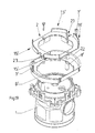
- a front side superior adapter 17 is attached on the can body 1.
- an auxiliary frame 2 is adjustably arranged, so that this as shown in FIG FIGS. 16 and 17 relative to the adapter 17 in the direction of the front side of the can body 1 and away from it is adjustable.
- This subframe 2 is intended to be an installation equipment carrier for the can body 1 built or installed Make installation equipment or keep a support ring for it.
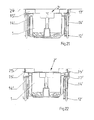
- FIGS. 20 to 22 is also an installation box for electrical purposes shown, which has an open installation opening for installation parts on a front side.
- an adapter 17 ' is arranged, which is intended for installation in an opening of a cavity wall and has means for attachment in the opening.
- the can body 1 is used as intended in the adapter 17 '.
- the can body 1 has an auxiliary frame 2 'at the front, which is fixedly connected to the can body 1, for example, by being screwed.
- the can body 1 together with the subframe 2 'relative to the adapter 17' in the adapter 17 'in and out of this adjustable.
- the subframe 2 ' forms an installation equipment carrier for built-in or installed in the can body 1 installation equipment or he holds a support ring for it.
- the adapter 17,17 'a directed transversely to the longitudinal extent of the can body 1 edge region 18,18' and one of which outside edge opposite the Front side of the can body 1 protruding collar 19,19 'on.
- the subframe 2, 2 ' has a flange edge 20, 20' and collar or collar parts 21, 21 'directed parallel to this edge region 18, 18' and collar 19, 19 '.
- the adapter 17,17' are directed away from the front side actuating means 8 'for adjusting means 7', in which parts of the adjusting means 7 ', in particular the threaded shank of adjusting screws designed as adjusting 7' engage.
- These adjusting means 7 ' are on the subframe 2,2' in regions 23 axially immovable, but rotatably arranged so that by rotation of the adjusting means 7 ', the distance of the subframe 2,2' of the adapter 17,17 'can be adjusted.
- the can body 1 has at the front at an orifice a radially outwardly projecting flange edge 5 '.
- the adapter 17,17 has an end face radially outwardly projecting flange edge 22 or Flanschrandmaschine.
- cover plate can take on different functions, so for example, can be integrated into these electrical switching elements or it can be arranged switches, push-button, sockets or other parts of installation devices.
- the cover plate is preferably releasably attached to a built-in the can body 1 support ring or on a built-in installation device, for example by means of screws or locking means.
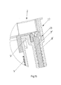
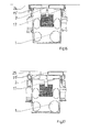
- FIG. 16 and FIG. 21 a situation is shown in which the installation box 1 together with subframe 2,2 'and adapter 17,17' is installed in a wall 24, so that the front side of this unit is flush with the outer surface of the wall concludes.
- FIG. 17 and in FIG. 22 It is shown that on the wall 24 a plaster layer is applied.
- the subframe 2,2' is displaced upwardly by means of the adjusting means 7 'in the drawing, wherein the displacement takes place so far that the ends of the webs 15' flush in the of the Plaster surface 25 spanned plane lie. It is thus an installation allows, which makes it possible to mount without overhang on the plaster surface 25 installation elements, in which case a cover plate can be applied, which only applies their material thickness on the plaster surface 25.
Landscapes
- Engineering & Computer Science (AREA)
- Architecture (AREA)
- Civil Engineering (AREA)
- Structural Engineering (AREA)
- Connection Or Junction Boxes (AREA)
- Connector Housings Or Holding Contact Members (AREA)
Abstract
Die Erfindung betrifft eine Installationsdose für elektrotechnische Zwecke zum Einbau in eine Wand mit einem mündungsseitig offenen Dosenkörper (1), wobei in den Dosenkörper (1) ein Hilfsrahmen (2) eingesetzt ist, der die Aufnahme und Halterung für ein in den Dosenkörper (1) einbaubares Installationsgerät und/oder einen in diesen einbaubaren Tragring (3) für ein Installationsgerät ist, und der Hilfsrahmen (2) mit seinem zur Mündung des Dosenkörpers (1) gerichteten Endbereich hinter der Mündungsebene des Dosenkörpers (1) zurückliegt.The invention relates to an installation box for electrical purposes for installation in a wall with a mouth side open can body (1), wherein in the can body (1) an auxiliary frame (2) is inserted, the receiving and mounting for a in the can body (1). einbaubares installation device and / or in this installable support ring (3) for an installation device is, and the subframe (2) with its to the mouth of the can body (1) directed end portion behind the mouth level of the can body (1).
Description
Die Erfindung betrifft eine Installationsdose für elektrotechnische Zwecke zum Einbau in eine Wand mit einem mündungsseitig offenen Dosenkörper.The invention relates to an installation box for electrical purposes for installation in a wall with a mouth side open can body.
Installationsdosen dieser Art sind im Stand der Technik vielfach bekannt. Zum Stand der Technik wird beispielsweise auf die
Installationsdosen sind in unterschiedlicher Ausgestaltung im Stand der Technik bekannt. Beispielsweise sind solche Installationsdosen als Unterputzinstallationsdosen ausgebildet, wie in der angegebenen Druckschrift beschrieben. Auch sind Installationsdosen bekannt, die als Hohlwanddosen beschrieben werden und die zum Einbau in eine Einbauöffnung einer Hohlwand bestimmt sind. In jedem Falle weist die entsprechende Wand einen Einbauraum für eine Installationsdose auf. Beispielsweise kann bei Unterputzinstallationsdosen ein entsprechendes Sackloch in der Wandung ausgebildet werden oder aber bei Hohlwanddosen wird in der Hohlwand ein Ausschnitt ausgeschnitten, dessen Querschnitt dem Querschnitt der Installationsdose entspricht, sodass die Installationsdose in den Ausschnitt eingesetzt werden kann.Installation boxes are known in different embodiments in the prior art. For example, such installation boxes are designed as flush-mounted installation boxes, as described in the cited document. Also, installation boxes are known, which are described as hollow wall boxes and which are intended for installation in a mounting hole of a cavity wall. In any case, the corresponding wall has an installation space for an installation box. For example, in the case of flush-mounted installation boxes, a corresponding blind hole can be formed in the wall or, in the case of hollow wall boxes, a cavity can be formed in the cavity wall Cut out section whose cross section corresponds to the cross section of the installation box so that the installation box can be inserted into the cutout.
Nach dem Einbau solcher Installationsdosen in entsprechende Wandöffnungen ist es üblich, dass die entsprechende Wand samt eingesetzter Installationsdose mit einer Putzschicht versehen wird, sodass die Installationsdose hinter der Außenfläche mit ihrer Mündung zurückliegt, die durch die Putzschicht gebildet ist.After installation of such installation boxes in corresponding wall openings, it is common that the corresponding wall is provided with installed installation box with a plaster layer, so that the installation box behind the outer surface with its mouth, which is formed by the plaster layer.
Um Installationsgeräte, beispielsweise Schalter, Tastschalter, Steckdosen oder dergleichen in solche Installationsdosen einbauen zu können, sind Tragringe bekannt, die mit einem entsprechenden Schalter, Taster, einer Steckdose oder dergleichen kombiniert werden. Diese Einbaueinheit wird dann in die Installationsdose eingesetzt, sodass der Tragring außen auf dem Mündungsrand der Installationsdose und/oder der Putzschicht, die gegenüber der Mündung der Installationsdose vorsteht, aufliegt. Die Lagesicherung des Installationsgerätes in der Installationsdose erfolgt beispielsweise dadurch, dass am Tragring Spreizkrallen angeordnet sind, welche mittels von der Vorderseite des Tragringes her zugänglicher Schrauben angezogen werden können, sodass die Spreizkrallen gegen den Mantel der Installationsdose angezogen werden und somit ein sicherer Sitz des Installationsgerätes in der Installationsdose erreicht wird. Um den Tragring an der Mündung der Installationsdose befestigen zu können, ist es außerdem bekannt, dass der Tragring schlüssellochartige Ausnehmungen aufweist, die von Befestigungsschrauben durchgriffen sind, die in das Installationsgerät eingeschraubt werden. Schließlich wird auf eine solche Anordnung eine Abdeckplatte aufgebracht und in geeigneter Weise am Installationsgerät oder am Tragring befestigt.In order to install installation equipment, such as switches, push buttons, sockets or the like in such installation boxes, support rings are known, which are combined with a corresponding switch, button, a socket or the like. This installation unit is then inserted into the installation box, so that the support ring rests on the outside on the mouth edge of the installation box and / or the plaster layer, which protrudes from the mouth of the installation box. The securing position of the installation device in the installation box, for example, by the fact that spreader claws are arranged on the support ring, which can be tightened by means of accessible from the front of the support ring ago screws, so that the spreader claws are tightened against the jacket of the installation box and thus a secure fit of the installation device in the installation box is reached. To attach the support ring to the mouth of the installation box to be able to, it is also known that the support ring has keyhole-like recesses, which are penetrated by fastening screws which are screwed into the installation device. Finally, a cover plate is applied to such an arrangement and secured in a suitable manner on the installation device or on the support ring.
Eine solche Ausgestaltung ist zwar zweckmäßig und auch brauchbar, jedoch besteht ein Problem darin, dass der Überstand des Installationsgerätes über die Außenfläche der Wand relativ groß ist, weil an der Außenfläche der Tragring und die Abdeckplatte anliegt, die gegenüber der Wandfläche vorragen.Although such an embodiment is convenient and useful, there is a problem in that the projection of the installation device on the outer surface of the wall is relatively large, because on the outer surface of the support ring and the cover plate is present, which protrude from the wall surface.
Insbesondere Anordnungen, bei denen aus Designgründen eine nahezu flächenbündige Anordnung der Abdeckplatte ermöglicht sein soll, sind mit solchen Konstruktionen nicht realisierbar.In particular arrangements in which, for design reasons, a nearly flush arrangement of the cover plate should be made possible, can not be realized with such constructions.
Ausgehend von diesem Stand der Technik liegt der Erfindung die Aufgabe zugrunde, eine Installationsdose gattungsgemäßer Art zu schaffen, die eine nahezu flächenbündige Anordnung einer Abdeckplatte bei einer entsprechenden Installationsdose ermöglicht, wobei ein Überstand durch einen Tragring oder sonstige Teile des Installationsgerätes vermieden ist.Based on this prior art, the present invention seeks to provide an installation box generic type, which allows a nearly flush arrangement of a cover plate in a corresponding installation box, with a supernatant is avoided by a support ring or other parts of the installation device.
Zur Lösung der Aufgabe schlägt die Erfindung vor, dass der Hilfsrahmen im Dosenkörper in Richtung auf einen Boden des Dosenkörpers und in Richtung zur Mündung des Dosenkörpers verstellbar und in unterschiedlichen Positionen feststellbar gehalten ist, der die Aufnahme und Halterung für ein in den Dosenkörper einbaubares Installationsgerät und/oder einen Tragring dafür ist.To solve the problem, the invention proposes that the subframe in the can body in the direction of a bottom of the can body and in the direction of the mouth of the can body is adjustable and lockable in different positions, the recording and support for a built-in can body installation device and / or a support ring for it.
Durch eine solche Ausgestaltung ist es ermöglicht, dass die relative Einbautiefe des Hilfsrahmens zum Dosenkörper der Installationsdose variabel ist, sodass die Einbautiefe an den örtlich vorliegenden Sollzustand angepasst werden kann.Such a configuration makes it possible that the relative mounting depth of the subframe to the can body of the installation box is variable, so that the installation depth can be adapted to the local present desired state.
Die Anpassung der Einbautiefe des Hilfsrahmens relativ zum Dosenkörper kann beispielsweise durch eine gewindemäßige Verstellung der Teile zueinander oder auch durch Rastung der Teile in unterschiedlichen Stellungen realisiert werden.The adjustment of the mounting depth of the subframe relative to the can body can be realized for example by a threaded adjustment of the parts to each other or by latching the parts in different positions.
Ist beispielsweise die Putzschicht, die nach Einsetzen der Installationsdose in die entsprechende Wandöffnung aufgebracht wird, relativ dick, so kann der Hilfsrahmen samt damit verbundener Teile weiter zur von der Wand gebildeten Außenfläche hin verschoben werden. Bei dünneren Putzschichten ist es möglich, den Hilfsrahmen im Dosenkörper tiefer zu versenken. In jedem Falle wird eine Einbausituation erreicht, bei der weder Bestandteile des Hilfsrahmens noch der daran befestigten Elemente mit Ausnahme einer möglicherweise vorhandenen Abdeckplatte oder dergleichen über die von der Wandung aufgespannte Ebene vorragen.For example, if the plaster layer, which is applied after insertion of the installation box in the corresponding wall opening, relatively thick, the subframe together with its associated parts can be further moved to the outer surface formed by the wall. For thinner plaster layers, it is possible to lower the subframe deeper in the can body. In any case, a mounting situation is achieved in which neither components of the subframe nor the attached elements with the exception of a possibly existing cover plate or the like protrude over the plane spanned by the wall level.
Der Dosenkörper kann beliebigen Querschnitt haben, beispielsweise polygonal, insbesondere quadratisch, wobei der Hilfsrahmen vorzugsweise der Querschnittsform angepasst ist.The can body may have any cross-section, for example polygonal, in particular square, wherein the subframe is preferably adapted to the cross-sectional shape.
In an sich bekannter Weise ist bevorzugt vorgesehen, dass der Dosenkörper kreisrunden Querschnitt hat.In a manner known per se, it is preferably provided that the can body has a circular cross-section.
Auch ist in an sich bekannte Weise vorgesehen, dass der Dosenkörper zylindrisch mit umlaufendem Mantel ausgebildet ist.It is also provided in a manner known per se, that the can body is formed cylindrically with circumferential mantle.
Installationsdosen mit kreisrundem Querschnitt und auch mit zylindrischem Mantel sind im Stand der Technik bekannt. Solche Installationsdosen sind Vorbild für die Installationsdose erfindungsgemäßer Art, wobei die erfindungsgemäße Installationsdose im Durchmesser größer als herkömmliche Installationsdosen ausgebildet ist, damit in der Installationsdose gemäß der Erfindung der Hilfsrahmen, die elektrischen Installationsgeräte und der Tragring versenkt angeordnet werden können.Installation boxes with a circular cross-section and also with a cylindrical jacket are known in the art. Such installation boxes are a model for the installation box inventive type, wherein the installation box according to the invention is larger in diameter than conventional installation boxes, so that in the installation box according to the invention, the subframe, the electrical installation equipment and the support ring can be placed sunk.
Dabei können insbesondere handelsübliche Installationsgeräte und gegebenenfalls sogar handelsübliche Tragringe verwendet werden, da der Durchmesser der erfindungsgemäßen Installationsdose entsprechend größer und den Zweckbestimmungen der Erfindung angepasst bemessen ist.In this case, in particular commercial installation equipment and possibly even commercially available support rings can be used, since the diameter of the installation box according to the invention correspondingly larger and the Purpose of the invention adapted dimensions.
Zudem kann vorgesehen sein, dass der Dosenkörper mündungsseitig quer zu seiner Längserstreckung nach außen abragende Gegenflächen aufweist, die in Einbausolllage an der Wandaußenseite neben der Einbauöffnung anliegen.In addition, it can be provided that the can body has muzzle side transversely to its longitudinal extension outwardly projecting mating surfaces which rest in installation target position on the wall outside next to the mounting hole.
Auch kann besonders bevorzugt vorgesehen sein, dass der Dosenkörper mündungsseitig außen umlaufend als Gegenlagerfläche einen Kragen oder Flanschrand aufweist.Also, it may be particularly preferred that the can body on the outlet side circumferentially outside as a counter bearing surface has a collar or flange.
Solche Ausgestaltungen dienen dazu, die Installationsdose in einfacher Art und Weise in eine Wandöffnung einsetzen zu können, wobei die Gegenlagerflächen bzw. der umlaufende Kragen eine Einstecktiefenbegrenzung für die Installationsdose bilden. Der Kragen und die Gegenlagerflächen sind im Mündungsbereich der Installationsdose vorgesehen, sodass die Installationsdose nicht über den Flanschrand bzw. über die Gegenlagerflächen nach außen vorragt. Nach Auftragen einer Putzschicht oder dergleichen auf die Wandfläche sind die Gegenlagerflächen von dieser überdeckt.Such configurations serve to be able to use the installation box in a simple manner in a wall opening, wherein the abutment surfaces or the circumferential collar form a Einstecktiefenbegrenzung for the installation box. The collar and the abutment surfaces are provided in the mouth area of the installation box, so that the installation box does not protrude beyond the flange or on the abutment surfaces to the outside. After applying a plaster layer or the like on the wall surface, the counter bearing surfaces are covered by this.
Insbesondere bei Einsatz der Installationsdose als Hohlwanddose dient der umlaufende Kragen bzw. dienen die an der Mündung vorgesehenen Gegenlagerflächen als Widerlager beim Anziehen der Befestigungsmittel zum Festsetzen der Hohlwanddose in dem Ausschnitt der Hohlwand.In particular, when using the installation box as a hollow wall box is the circumferential collar or serve provided at the mouth abutment surfaces as an abutment when tightening the fasteners for fixing the cavity wall box in the cutout of the cavity wall.
Es ist zudem vorzugsweise vorgesehen, dass der Hilfsrahmen als Ringkörper ausgebildet ist, von dem am der Mündung des Dosenkörpers zugewandten Endbereich ein Kragen quer nach außen abragt.It is also preferably provided that the subframe is designed as a ring body, projects from the at the mouth of the can body end facing a collar transversely outwards.
Der Ringkörper hat eine ausreichende Höhe, wie es seiner Zweckbestimmung entspricht. Der am einen Ende des Ringkörpers vorgesehene Kragen ist bei der Anordnung der Befestigungsmittel für die einzelnen Elemente vorteilhaft, insbesondere der Mittel, mittels derer der Hilfsrahmen in dem Dosenkörper verstellbar gehalten ist.The ring body has a sufficient height, as it corresponds to its purpose. The provided at one end of the annular body collar is advantageous in the arrangement of the fastening means for the individual elements, in particular the means by means of which the subframe is held adjustably in the can body.
Besonders bevorzugt ist dabei vorgesehen, dass am Hilfsrahmen Stellmittel gehalten sind, die mit Stellmittelaufnahmen am Innenmantel des Dosenkörpers in Eingriff sind und mittels derer die Verstellung und Feststellung in unterschiedlichen Positionen realisiert ist.Particularly preferably, it is provided that adjusting means are held on the subframe, which are engaged with Stellmittelaufnahmen on the inner surface of the can body and by means of which the adjustment and detection is realized in different positions.
Hierbei kann vorgesehen sein, dass die Stellmittel Kopfschrauben sind, deren Kopf jeweils in einem am Außenmantel des Hilfsrahmens ausgebildeten Käfig drehbar, aber axial unverstellbar gehalten ist und deren Gewindeschaft in einen die Stellmittelaufnahme bildenden Kanal am Innenmantel des Dosenkörpers eingeschraubt ist.It can be provided that the adjusting means are cap screws whose head is held rotatably in a cage formed on the outer casing of the subframe, but axially immovable and whose threaded shaft is screwed into a channel forming the Stellmittelaufnahme on the inner surface of the can body.
Die Anordnung der Stellmittel ist vorzugsweise am Außenmantel des Hilfsrahmens vorgesehen, wobei zum Zugriff zu den Stellmitteln der Kragen über die Stellmittel zwar radial vorragt, im Bereich der Stellmittel aber Ausnehmungen aufweist, die beispielsweise mit einem Werkzeug durchgreifbar sind. Am Innenmantel der Installationsdose sind im Bereich der am Hilfsrahmen angeordneten Stellmittel entsprechende Stellmittelaufnahmen ausgebildet, in die die Stellmittel in der Sollposition eingreifen und mittels derer die Verstellung des Hilfsrahmens in unterschiedlichen Positionen relativ zur Installationsdose ermöglicht ist. Vorzugsweise sind die Stellmittel Kopfschrauben, deren Kopf jeweils in einem am Außenmantel des Hilfsrahmens ausgebildeten Käfig drehbar gehalten ist, aber axial unverstellbar, sodass durch Drehung der Kopfschrauben die Einschraubtiefe des Gewindeschaftes in den Kanal am Innenmantel der Installationsdose variabel ist. Beim Drehen der Kopfschraube und entsprechendem gewindebedingten Einschrauben oder Herausschrauben aus der Installationsdose wird der Hilfsrahmen mitbewegt und auf das entsprechende Niveau eingestellt.The arrangement of the adjusting means is preferably provided on the outer casing of the subframe, wherein for access to the actuating means of the collar projecting radially beyond the actuating means, in the area but the adjusting means has recesses, which are durchgreifbar example with a tool. On the inner jacket of the installation box corresponding adjusting means receptacles are formed in the region of the subframe arranged adjusting means, in which engage the actuating means in the desired position and by means of which the adjustment of the subframe is possible in different positions relative to the installation box. Preferably, the adjusting means head screws whose head is rotatably supported in each case in a formed on the outer casing of the subframe cage, but axially immovable, so that the screwing of the threaded shaft into the channel on the inner shell of the installation box is variable by rotation of the cap screws. When turning the cap screw and corresponding thread-related screwing or unscrewing from the installation box of the subframe is moved and adjusted to the appropriate level.
Des Weiteren ist bevorzugt vorgesehen, dass der Hilfsrahmen am Innenmantel Kanäle, die parallel zu einer Mittellängsachse des Hilfsrahmens ausgerichtet sind, aufweist, und dass Haltemittel, insbesondere Kopfschrauben, in diese einschraubbar oder eingeschraubt sind, mittels derer ein Installationsgerät oder ein Tragring, der ein Installationsgerät hält, am Hilfsrahmen befestigt oder befestigbar ist.Furthermore, it is preferably provided that the subframe on the inner casing channels which are aligned parallel to a central longitudinal axis of the subframe has, and that retaining means, in particular cap screws are screwed or screwed into this, by means of which an installation device or a support ring, the installation device holds, is attached to the subframe or fastened.
Durch diese Ausgestaltung ist es in einfacher Weise möglich, einen Tragring, gegebenenfalls einen Tragring mit Installationsgerät, oder auch ein Installationsgerät im Hilfsrahmen zu fixieren, sodass diese Elemente gemeinsam mit dem Hilfsrahmen relativ zur Installationsdose hinsichtlich der Einbautiefe variabel sind.By this configuration, it is possible in a simple manner, a support ring, if necessary to fix a support ring with installation device, or even an installation device in the subframe so that these elements are variable relative to the installation box with respect to the installation depth together with the subframe.
Auch kann bevorzugt sein, dass der Dosenkörper als Hohlwanddose ausgebildet ist, an deren Mantel ein- und ausschwenkbare Laschen angeordnet sind, die mittels in Kanäle des Dosenkörpers eingesetzter Laschenschrauben betätigbar und in ausgeschwenkter Lage längs des Mantels in Richtung zur Mündung verstellbar sind.Also, it may be preferred that the can body is formed as a hollow wall box, on the jacket are arranged on and swing-out tabs which are actuated by means inserted in channels of the can body strap bolts and adjustable in the swung position along the jacket in the direction of the mouth.
Solche Ausgestaltungen sind bei Hohlwanddosen an sich bekannt.Such embodiments are known in hollow wall boxes per se.
Eine bevorzugte Weiterbildung wird zudem darin gesehen, dass am Hilfsrahmen an seiner zur Mündung weisenden Seite parallel zur Stellrichtung mindestens ein vorragender Steg angeordnet ist.A preferred development is also seen in that at least one protruding web is arranged on the subframe on its side facing the mouth parallel to the direction of adjustment.
Durch den am Hilfsrahmen zur Mündung ragenden Steg kann der Monteur, der die Installationsdose samt Hilfsrahmen und dergleichen installiert, in einfacher Weise die Einbautiefe des Hilfsrahmens relativ zur außenliegenden Wandoberfläche erkennen und einstellen, in dem nämlich die vorragenden Stege bei Verstellung des Hilfsrahmens relativ zur Installationsdose dann die gewünschte Einbautiefe anzeigen, wenn die freien Stegenden in der von der Wand oder der darauf befindlichen Putzschicht aufgespannten Bezugsebene liegen.By projecting on the subframe to the muzzle bridge, the installer who installed the installation box together with subframe and the like, easily recognize and adjust the depth of the subframe relative to the outer wall surface, namely in the namely the projecting webs on adjustment of the subframe relative to the installation box then indicate the desired installation depth, if the free web ends in the of the wall or the lie thereon plaster layer spanned reference plane.
Um eine entsprechende Montagehilfe zu bieten, sind vorzugsweise mehrere gleichlange Stege vorgesehen, beispielsweise 3 oder 4 gleichmäßig auf den Umfang des Hilfsrahmens verteilt.In order to provide a corresponding assembly aid, preferably several equal length webs are provided, for example, 3 or 4 evenly distributed over the circumference of the subframe.
Eine mögliche Variante wird darin gesehen, dass der Hilfsrahmen als mündungsseitig offener Dosenkörper ausgebildet ist.A possible variant is seen in the fact that the subframe is designed as a mouth-open can body.
Es ist nicht zwingend erforderlich, dass der Hilfsrahmen als offener Ringkörper ausgebildet ist. Der Hilfsrahmen könnte auch als offener Dosenkörper ausgebildet sein, der dazu bestimmt und dazu geeignet ist, entsprechende Installationsgeräte aufzunehmen. Hierbei muss lediglich eine Anpassung insoweit vorgenommen werden, als beispielsweise in der Installationsdose vorgesehene Sollbruchstellen, Ausschnitte oder dergleichen, die zur Kabeleinführung und -abführung dienen, auch in dem als offenem Dosenkörper ausgebildeten Hilfsrahmen vorgesehen sind, damit entsprechende Kabelanschlüsse und dergleichen in das Innere des offenen Dosenkörpers geführt werden können. Bei einem offenen ringförmigen Hilfsrahmen ist eine Öffnung um Zuführen von Kabeln oder dergleichen ohnehin vorhanden.It is not mandatory that the subframe is designed as an open ring body. The subframe could also be designed as an open can body, which is intended and adapted to accommodate appropriate installation equipment. Here, only an adjustment must be made insofar as provided for example in the installation box predetermined breaking points, cutouts or the like, which are used for cable entry and removal, are also provided in the form of an open can body subframe so that corresponding cable connections and the like in the interior of the open Can body can be performed. In an open annular subframe, there is an opening for feeding cables or the like anyway.
Eine unter Umständen bevorzugte Weiterbildung wird darin gesehen, dass die Gegenlagerfläche in Form des umlaufenden Mündungsrandes aneinander gegenüberliegenden Bereichen oder zumindest an einem Randbereich Sollbruchstellen aufweist, an denen der Mündungsrand zur Erzeugung einer tangential gerichteten oder als Sekante ausgebildeten flachen Randkante abbrechbar ist.A possibly preferred development is seen in that the abutment surface in the form of the circumferential mouth edge together opposite areas or at least at one edge region has predetermined breaking points at which the mouth edge for generating a tangentially directed or formed as a secant flat peripheral edge is breakable.
Diese Ausgestaltung dient dazu, eine enge Anlage von nebeneinander installierten Installationsdosen zu ermöglichen, die an sich kreisrunden Querschnitt aufweisen. Durch die Abflachung ist es möglich, die benachbarten Dosen mit der durch die Abflachung erzeugten Fläche aneinander zu führen, sodass der Standard-Einbauabstand erreicht werden kann.This configuration serves to allow a close system of installation boxes installed side by side, which have a circular cross-section per se. The flattening makes it possible to bring the adjacent cans together with the surface created by the flattening, so that the standard installation distance can be achieved.
Eine unter Umständen bevorzugte Weiterbildung wird zudem darin gesehen, dass in den Dosenkörper ein dessen Innenabmessung oder Innendurchmesser angepasster Tragring eingesetzt ist, der auf der Mündung des Hilfsrahmens aufliegt.A possibly preferred development is also seen in the fact that in the can body an inner dimension or inner diameter adapted support ring is used, which rests on the mouth of the subframe.
Gemäß dieser Ausgestaltung ist der entsprechende Tragring hinsichtlich seiner Bemessung und geometrischen Ausgestaltungen so ausgebildet, dass er zwängungsfrei in die Installationsdose eingefügt werden kann.According to this embodiment, the corresponding support ring is designed in terms of its design and geometric configurations so that it can be inserted without constraint in the installation box.
Insbesondere ist bevorzugt vorgesehen, dass der Dosenkörper in der Einbausolllage von einer Abdeckplatte überdeckt ist, in die elektrische Schaltelemente integriert sind oder die Durchgriffe für Schalter, Tastschalter, Steckdosen oder dergleichen Teile von elektrischen Installationsgeräten aufweist, wobei die Abdeckplatte vorzugsweise am Tragring oder an einem eingebauten Installationsgerät lösbar befestigt ist, z.B. mittels Rasten oder Schrauben.In particular, it is preferably provided that the can body is covered in the installation target position of a cover plate, are integrated in the electrical switching elements or the passages for switches, push-button, sockets or the like parts of electrical installation equipment, wherein the cover plate is preferably releasably attached to the support ring or to a built-in installation device, for example by means of detents or screws.
Des Weiteren betrifft die Erfindung eine Installationsdose für elektrotechnische Zwecke zum Einbau in eine Wand mit einem Dosenkörper mit einer an einer Frontseite offenen oder zu öffnenden Einbauöffnung für Installationsteile.Furthermore, the invention relates to an installation box for electrical purposes for installation in a wall with a can body with an open at the front or opening opening for installation parts.
Im Stand der Technik sind Installationsdosen unterschiedlicher Art bekannt. Beispielsweise ist aus der
Aus der
Üblicherweise sind solche Installationsdosen im Querschnitt kreisrund, da eine entsprechende Öffnung in einer Wand zum Einsatz einer solchen Dose oder eine Lochung in einer Hohlwand zum Einbau einer solchen Dose am einfachsten in kreisrunder Form erzeugt werden kann. Dennoch sind abweichende Querschnittsformen der Installationsdosen möglich. Diese können durchaus auch polygonal ausgebildet sein oder bei kreisrunder Ausgestaltung mit abgeflachten gegenüberliegenden Seitenflächen ausgestaltet sein.Typically, such installation boxes are circular in cross-section, since a corresponding opening in a wall for use of such a box or a hole in a cavity wall for installation of such a can most easily be generated in a circular shape. Nevertheless, different cross-sectional shapes of the installation boxes are possible. These may well be formed polygonal or in a circular configuration with flattened Be configured opposite side surfaces.
Ein weiterer Typ von Installationsdose ist eine sogenannte Betonbaudose, die in Betonfertigteile einbetoniert wird. Solche Betonbaudosen sind von ihrem Querschnitt von der Einbauart unabhängig, da sie üblicherweise an der Schalung einer Betonschalung angenagelt werden und von Bewehrungsmaterial abgedeckt werden. Der Verguss erfolgt dann mit Betonmasse. Es ist dafür völlig gleichgültig, welche Querschnittsform eine solche Installationsdose hat. Typisch für solche Installationsdosen, die zum Einbau als Betonbaudosen geeignet und bestimmt sind, ist, dass diese allseitig geschlossen sind, also entgegen der Hohlwanddose und der Unterputzdose keine offene Mündung aufweisen, sondern die Mündung ist durch einen Deckel oder ein Verschlussteil verschlossen. Nach dem Betonieren und Ausschalen des entsprechenden Betonteiles liegt dieser Deckel oder dergleichen frei und kann mittels eines geeigneten Werkzeuges ausgeschnitten werden, sodass dann der Einbauraum der Betonbaudose für den Einbau von Installationsteilen zur Verfügung steht.Another type of installation box is a so-called concrete building box, which is embedded in precast concrete elements. Such concrete building blocks are independent of their cross-section of the installation, as they are usually nailed to the formwork of concrete formwork and covered by reinforcing material. The potting then takes place with concrete mass. It is completely indifferent, which cross-sectional shape has such an installation box. Typical of such installation boxes, which are suitable and intended for installation as concrete building blocks, is that they are closed on all sides, so contrary to the hollow wall box and the flush box have no open mouth, but the mouth is closed by a lid or a closure part. After concreting and stripping the corresponding concrete part of this cover or the like is free and can be cut out by means of a suitable tool, so that then the installation space of the concrete wall box for the installation of installation parts is available.
Nach dem Einbau solcher Installationsdosen in entsprechende Wandöffnungen ist es üblich, dass die entsprechende Wand, gleichgültig welche Bauart eingesetzt wird, samt eingesetzter Installationsdose mit einer Putzschicht versehen wird, auf die gegebenenfalls noch Deckschichten aufgebracht werden. Somit liegt die Installationsdose mit ihrer Mündung hinter der durch die Putzschicht oder dergleichen gebildeten Außenfläche zurück.After installation of such installation boxes in corresponding wall openings, it is common that the corresponding wall, regardless of which type is used, is provided with installed installation box with a plaster layer on which, if necessary, cover layers are applied. Thus lies the Installation box with its mouth behind the outer surface formed by the plaster layer or the like.
Um Installationsgeräte, beispielsweise Schalter, Tastschalter, Steckdosen oder dergleichen in solche Installationsdosen einbauen zu können, sind Tragringe bekannt, die mit einem entsprechenden Schalter, Taster, einer Steckdose oder dergleichen kombiniert werden. Eine solche Einbaueinheit kann dann in die Mündung der Installationsdose eingesetzt werden, sodass der Tragring außen auf dem Mündungsrand der Installationsdose und/oder auf der Putzschicht, die gegenüber der Mündung der Installationsdose vorsteht, aufliegt. Die Lagesicherung des Installationsgerätes in der Installationsdose erfolgt üblicherweise dadurch, dass am Tragring Spreizkrallen angeordnet sind, welche mittels von der Vorderseite des Tragringes her zugänglicher Schrauben angezogen werden können, sodass die Spreizkrallen gegen den Mantel der Installationsdose angezogen werden und somit ein sicherer Sitz des Installationsgerätes in der Installationsdose erreicht wird. Um den Tragring an der Mündung der Installationsdose befestigen zu können, ist es zudem bekannt, dass der Tragring schlüssellochartige Ausnehmungen aufweist, die von Befestigungsschrauben durchgriffen sind, die in das Installationsgerät eingeschraubt werden. Schließlich kann auf eine solche Anordnung eine Abdeckplatte aufgebracht werden und in geeigneter Weise am Installationsgerät oder am Tragring befestigt werden.In order to install installation equipment, such as switches, push buttons, sockets or the like in such installation boxes, support rings are known, which are combined with a corresponding switch, button, a socket or the like. Such a mounting unit can then be inserted into the mouth of the installation box, so that the support ring rests on the outside of the mouth edge of the installation box and / or on the plaster layer, which protrudes from the mouth of the installation box. The securing position of the installation device in the installation box is usually characterized in that the support ring Spreizkrallen are arranged, which can be tightened by means of accessible from the front of the support ring forth screws, so that the Spreizkrallen be tightened against the jacket of the installation box and thus a secure fit of the installation device in the installation box is reached. In order to attach the support ring at the mouth of the installation box, it is also known that the support ring has keyhole-like recesses, which are penetrated by fastening screws which are screwed into the installation device. Finally, a cover plate can be applied to such an arrangement and suitably on Installation device or attached to the support ring.
Eine solche Ausgestaltung ist zwar zweckmäßig und auch brauchbar, jedoch besteht ein Problem darin, dass der Überstand des Installationsgerätes über die Außenfläche der Wand relativ groß ist, weil an der Außenfläche beispielsweise der Tragring und die Abdeckplatte anliegt, die gegenüber der Randfläche vorragt.Although such an embodiment is useful and useful, but there is a problem in that the projection of the installation device on the outer surface of the wall is relatively large, because on the outer surface, for example, the support ring and the cover plate abuts, which protrudes from the edge surface.
Vornehmlich bei Anordnungen, bei denen aus Designgründen eine nahezu flächenbündige Anordnung der Abdeckplatte ermöglicht sein sollen, sind mit solchen Konstruktionen nicht realisierbar.Primarily in arrangements in which, for design reasons, a nearly flush arrangement of the cover plate should be made possible, can not be realized with such constructions.
Ausgehend von diesem Stand der Technik liegt der Erfindung die Aufgabe zugrunde, Installationsdosen gattungsgemäßer Art zu schaffen, die eine nahezu flächenbündige Anordnung einer Abdeckplatte bei einer entsprechenden Installationsdose im Einbauzustand ermöglicht, wobei ein Überstand durch einen Tragring oder sonstige Teile des Installationsgerätes vermieden ist. Insbesondere sollen diese Installationen ermöglicht sein unabhängig von der Dicke der Putzschicht oder dergleichen, die auf eine entsprechende Wandfläche nach der Installation der Installationsdose aufgebracht wird.Based on this prior art, the present invention seeks to provide installation boxes generic type, which allows a nearly flush arrangement of a cover at a corresponding installation box in the installed state, with a supernatant is avoided by a support ring or other parts of the installation device. In particular, these installations should be possible regardless of the thickness of the plaster layer or the like, which is applied to a corresponding wall surface after installation of the installation box.
Eine erste Lösung dieser Aufgabe schlägt erfindungsgemäß vor, dass an dem Dosenkörper ein dessen Frontseite überragender Adapter befestigt ist und dass in dem Adapter ein Hilfsrahmen gegenüber dem Adapter in Richtung zur Frontseite des Dosenkörpers und von diesem weg verstellbar angeordnet ist, der einen Installationsgeräteträger für in den Dosenkörper eingebaute oder einbaubare Installationsgeräte bildet oder einen Tragring dafür hält.A first solution to this problem proposes according to the invention that on the can body a the front of which superior adapter is attached and that in the adapter, a subframe relative to the adapter in the direction of the front of the can body and away from this is arranged adjustable, which forms an installation equipment carrier for built-in or installable in the can body installation equipment or holds a support ring for it.
Eine solche Ausgestaltung ist sowohl für sogenannte Unterputzdosen als auch für sogenannte Betonbaudosen brauchbar. Gemäß der Erfindung wird an den Dosenkörper an dessen Frontseite, die die Einbauöffnung aufweist, ein überragender Adapter befestigt. Der Adapter kann beispielsweise eine kreisförmige Ausnehmung aufweisen, die der vorzugsweise kreisförmigen Öffnung der Installationsdose angepasst ist. Die Außenabmessung des Adapters kann ringförmig sein oder auch polygonal. Ein solcher Adapter wird mit geeigneten Maßnahmen fest mit dem Dosenkörper verbunden, sodass diese beiden Teile eine Einbaueinheit bilden. Bei einer Unterputzdose kann diese Einheit in die entsprechende Ausnehmung der Wand oder dergleichen eingebaut werden, wobei in der Einbausituation der dem Dosenkörper abgewandte Rand des Adapters bündig in der Wandfläche angeordnet ist. Bei einer Betonbaudose kann der entsprechende Adapter schon vor dem Betonieren an der entsprechenden Installationsdose fixiert werden. Es ist aber auch möglich, den Adapter erst nach dem Vergießen der Installationsdose mit Beton und nach Entfernen der Schalung aufzusetzen und mit dem Dosenkörper zu verbinden. Auch hierbei liegt die dem Dosenkörper abgewandte Randkante dann im Wesentlichen bündig in der Wandfläche des Betonteiles.Such a configuration is useful both for so-called flush-mounted boxes and for so-called concrete building blocks. According to the invention, a protruding adapter is attached to the can body on its front side, which has the installation opening. The adapter may for example have a circular recess which is adapted to the preferably circular opening of the installation box. The outer dimension of the adapter may be annular or polygonal. Such an adapter is connected with suitable measures firmly to the can body, so that these two parts form a mounting unit. In the case of a flush-mounted box, this unit can be installed in the corresponding recess of the wall or the like, wherein in the installation situation the edge of the adapter facing away from the can body is arranged flush in the wall surface. With a concrete building box, the corresponding adapter can be fixed to the corresponding installation box before concreting. But it is also possible to put the adapter after pouring the installation box with concrete and after removing the formwork and with the To connect can body. Again, the edge facing away from the can body is then substantially flush in the wall surface of the concrete part.
In diesen Adapter ist ein Hilfsrahmen eingesetzt, der in einer Endlage bündig hinter der Randkante des Adapters zurückliegt oder mit dieser abschließt, die dem Dosenkörper abgewandt ist. Dieser Hilfsrahmen ist gegenüber dem Adapter derart verstellbar, dass er auch in eine Position verstellbar ist, in der er gegenüber dem Adapter nach außen, also in Richtung der Öffnung der Wandfläche verstellbar ist.In this adapter, a subframe is used, which lies in an end position flush behind the peripheral edge of the adapter or terminates with this, which faces away from the can body. This subframe is adjustable with respect to the adapter in such a way that it can also be adjusted to a position in which it is adjustable relative to the adapter towards the outside, that is to say in the direction of the opening of the wall surface.
Je nach Dicke der auf die Wandfläche samt Installationsdose im Einbauzustand aufgebrachten Putzschicht oder dergleichen kann der Hilfsrahmen gegenüber dem Adapter entsprechend eingestellt und verstellt werden, sodass der Hilfsrahmen als Montageelement für Installationsgeräte oder Tragringe noch ausreichend hinter der von dem Putz aufgespannten Ebene liegt, aber gegenüber dem zurückliegenden Adapter vorverlagert ist. Hiermit wird erreicht, dass die in die Installationsdose eingebauten und am Hilfsrahmen gehalterten Elemente soweit nötig vorverlagert sind, aber hinter der von der Putzschicht oder dergleichen gebildeten Montageebene zurückliegen oder allenfalls in dieser Ebene liegen. Damit ist es möglich, einen nahezu flächenbündigen Einbau einer auf die Installationsdose aufgebrachten Abdeckplatte, Zierblende oder dergleichen zu realisieren.Depending on the thickness of the wall surface including installation box in the installed state applied plaster layer or the like, the subframe relative to the adapter can be adjusted and adjusted accordingly, so that the subframe as a mounting element for installation equipment or support rings still sufficiently behind the plane spanned by the plaster level, but against the previous adapter is relocated. This ensures that the built-in installation box and content Erten on the subframe elements are vorverlagert as necessary, but lie behind the mounting plane formed by the plaster layer or the like or at most lie in this plane. This makes it possible to realize a nearly flush installation of an applied to the installation box cover plate, trim or the like.
Eine zweite Lösung der Aufgabe ist dadurch gekennzeichnet, dass ein Adapter angeordnet ist, der zum Einbau in eine Öffnung einer Hohlwand bestimmt ist und Mittel zur Befestigung in der Öffnung aufweist, dass der Dosenkörper in den Adapter eingesteckt ist, wobei der Dosenkörper frontseitig einen Hilfsrahmen aufweist, der fest mit dem Dosenkörper verbindbar oder verbunden ist, und dass der Dosenkörper samt Hilfsrahmen gegenüber dem Adapter in den Adapter und aus dem Adapter verstellbar angeordnet ist, wobei der Hilfsrahmen einen Installationsgeräteträger für in den Dosenkörper eingebaute oder einbaubare Installationsgeräte bildet oder einen Tragring dafür hält.A second solution of the problem is characterized in that an adapter is arranged, which is intended for installation in an opening of a cavity wall and means for attachment in the opening, that the can body is inserted into the adapter, wherein the can body front side has an auxiliary frame which is firmly connected or connected to the can body, and that the can body including subframe relative to the adapter in the adapter and from the adapter is adjustably arranged, wherein the subframe forms an installation equipment carrier built into the can body or installable installation equipment or holds a support ring for it ,
Hierbei ist eine Lösung für eine Hohlwanddose angegeben. Dabei ist ein Adapter vorgesehen, der in die Öffnung einer Hohlwand eingesetzt wird und mittels geeigneter Befestigungsmittel in dieser Position an der Hohlwand fixiert wird. Der Dosenkörper, der eine übliche Hohlwanddose sein kann, ist dann in den Adapterring eingesteckt, wobei der Dosenkörper frontseitig den Hilfsrahmen aufweist, der fest mit dem Dosenkörper verbindbar ist. Der Dosenkörper bildet also mit dem Hilfsrahmen eine Einheit. Diese Einheit ist gegenüber dem fest installierten Adapter verstellbar, also in den Adapter hinein oder aus dem Adapter heraus verstellbar angeordnet, sodass eine Anpassung an die Einbausituation bezüglich des Niveaus der Wandfläche, die mit einer Putzfläche ausgestattet ist, erreicht wird. Auch hierbei bildet der Hilfsrahmen einen Installationsgeräteträger für in den Dosenkörper eingebaute oder einbaubare Installationsgeräte oder einen Tragring dafür.Here, a solution for a cavity wall box is given. In this case, an adapter is provided, which is inserted into the opening of a hollow wall and is fixed by means of suitable fastening means in this position on the cavity wall. The can body, which may be a conventional hollow wall box, is then inserted into the adapter ring, wherein the can body front side has the subframe, which is fixedly connected to the can body. The can body thus forms a unit with the subframe. This unit is adjustable with respect to the permanently installed adapter, that is adjustable into the adapter or out of the adapter, so that an adaptation to the installation situation with respect to the level of the wall surface, which is equipped with a plaster surface is achieved. Also In this case, the subframe forms an installation equipment carrier for built-in or installable in the can body installation equipment or a support ring for it.
Der besondere Vorteil der erfindungsgemäßen Ausgestaltung, der für beide angegebenen Lösungen gilt, ist, dass bisher übliche Installationsdosen der unterschiedlichen Bauarten ohne weitere Änderungen einsetzbar sind, also übliche Hohlwanddosen, übliche Unterputzdosen und übliche Betonbaudosen, wobei diese lediglich mit dem entsprechenden Adapter bzw. mit dem zusätzlichen Hilfsrahmen kombiniert werden. Der Hilfsrahmen kann für alle Lösungen identisch sein. Lediglich der Adapter unterscheidet eine Ausführungsform, die für Unterputzdosen und Betonbaudosen geeignet ist, und eine zweite Ausführungsform, die für Hohlwanddosen geeignet und bestimmt ist.The particular advantage of the embodiment of the invention, which applies to both solutions, is that previously common installation boxes of different types are used without further changes, ie usual cavity wall boxes, common wall outlets and conventional concrete wall boxes, these only with the corresponding adapter or with the additional subframe can be combined. The subframe can be identical for all solutions. Only the adapter distinguishes an embodiment which is suitable for flush-mounted boxes and concrete building boxes, and a second embodiment which is suitable and intended for cavity wall boxes.
Vorzugsweise ist der Hilfsrahmen relativ zum Adapter in Richtung auf einen Bodenrand des Adapters und in Richtung zur Mündung der Wandöffnung verstellbar und in unterschiedlichen Positionen feststellbar gehalten. Durch eine solche Ausgestaltung ist es möglich, dass die relative Einbautiefe des Hilfsrahmens relativ zum Adapter variabel ist, sodass die Einbautiefe an den örtlich vorliegenden Sollzustand angepasst werden kann. Die Anpassung der Einbautiefe des Hilfsrahmens kann relativ zum Adapter beispielsweise durch eine gewindemäßige Verstellung der Teile zueinander oder auch durch Rastung der Teile in unterschiedlichen Stellungen realisiert werden.Preferably, the subframe is held relative to the adapter towards a bottom edge of the adapter and towards the mouth of the wall opening adjustable and lockable in different positions. By such a configuration, it is possible that the relative mounting depth of the subframe is variable relative to the adapter, so that the mounting depth can be adapted to the local present desired state. The adjustment of the mounting depth of the subframe relative to the adapter, for example, by a threaded adjustment of the parts to each other or by Rastung the parts can be realized in different positions.
Ist beispielsweise die Putzschicht, die nach Einsetzen der Installationsdose samt Adapter bzw. des Adapters in die entsprechende Wandöffnung aufgebracht wird, relativ dick, so kann der Hilfsrahmen samt damit verbundener Teile weiter zur von der Wand gebildeten Außenfläche hin verschoben werden. Bei dünneren Putzschichten ist es möglich, den Hilfsrahmen im Adapter tiefer zu versenken. In jedem Falle ist eine Einbausituation einstellbar, bei der weder Bestandteile des Hilfsrahmens noch der daran befestigten Elemente mit Ausnahme einer möglicherweise vorhandenen Abdeckplatte oder dergleichen über die von der verputzten Wandung aufgespannte Ebene vorragen. Die Querschnittsform des Dosenkörpers und ebenso die Querschnittsform des Adapters und des Hilfsrahmens kann beliebig sein, beispielsweise polygonal, insbesondere quadratisch oder auch kreisrund, wobei lediglich das Zusammenwirken der Teile miteinander sichergestellt sein muss.For example, if the plaster layer, which is applied after insertion of the installation box including adapter or the adapter in the corresponding wall opening, relatively thick, the subframe together with its associated parts can be further moved to the outer surface formed by the wall. For thinner plaster layers, it is possible to lower the subframe deeper in the adapter. In any case, a mounting situation is adjustable, in which neither components of the subframe nor the elements attached thereto with the exception of a possibly existing cover plate or the like project beyond the plane spanned by the plastered wall level. The cross-sectional shape of the can body and also the cross-sectional shape of the adapter and the subframe may be arbitrary, for example polygonal, in particular square or circular, with only the interaction of the parts must be ensured together.
Der Adapter, der zum Einbau in eine Öffnung einer Hohlwand bestimmt ist und die entsprechenden Mittel zur Befestigung in deren Öffnung aufweist, kann als offener Ring ausgebildet sein. Es ist aber auch möglich, den Adapter mit einer umfangseitigen dünnen Wandung und einem Boden in gleicher Ausgestaltung zu versehen, um insbesondere eine luftdichte Anordnung in einer Hohlwandöffnung zu erreichen. Die dünne Wandung kann eine Haut oder Folie sein.The adapter, which is intended for installation in an opening of a cavity wall and having the corresponding means for attachment in the opening, may be formed as an open ring. But it is also possible to provide the adapter with a circumferential thin wall and a bottom in the same configuration, in particular an airtight arrangement in one Cavity wall opening to achieve. The thin wall can be a skin or foil.
Bei den anderen Ausführungsvarianten ist vorzugsweise der Adapter als offener Ring ausgestaltet.In the other embodiments, the adapter is preferably designed as an open ring.
Eine bevorzugte Weiterbildung wird darin gesehen, dass der Adapter einen quer zur Längserstreckung des Dosenkörpers gerichteten Randbereich und einen davon außenrandseitig gegenüber der Frontseite des Dosenkörpers vorragenden Kragen oder Kragenteile aufweist und dass der Hilfsrahmen einen parallel zu diesem Randbereich und Kragen gerichteten Flanschrand und Kragen oder Kragenteile aufweist.A preferred development is seen in that the adapter has a transversely directed to the longitudinal extent of the can body edge region and one of the outside edge opposite the front of the can body protruding collar or collar parts and that the subframe has a parallel to this edge region and collar flange edge and collar or collar parts ,
Diese Formgebung des Adapters ist bezüglich des Einbaus des Adapters in die entsprechende Wandöffnung oder in das entsprechende Betonbauteil förderlich, wobei zudem durch den Randbereich und den davon abragenden Kragen eine entsprechend passende Aufnahme für den Hilfsrahmen gebildet ist. Der Hilfsrahmen kann in einer Montageposition mit seinem Flanschrand an den Randbereich des Adapters angelegt werden und liegt mit seinem Kragen parallel zum Kragen des Adapters ausgerichtet.This shaping of the adapter is conducive with respect to the installation of the adapter in the corresponding wall opening or in the corresponding concrete component, wherein in addition a correspondingly fitting receptacle for the subframe is formed by the edge region and the collar projecting therefrom. The subframe can be applied in a mounting position with its flange edge to the edge region of the adapter and is aligned with its collar parallel to the collar of the adapter.
Bevorzugt ist ferner vorgesehen, dass am Randbereich des Adapters von der Frontseite weg gerichtete Stellmittelaufnahmen für Stellmittel oder Stellschrauben ausgebildet sind, in die Teile der Stellmittel oder der Gewindeschaft von Stellschrauben eingreifen oder eingreift, die am Hilfsrahmen axial unverschieblich, aber drehbar angeordnet sind.Preferably, it is further provided that at the edge region of the adapter directed from the front side actuating means shots are formed for adjusting means or screws in the parts of the actuating means or the threaded shaft of Engage or engage screws that are arranged on the subframe axially immovable, but rotatable.
Hierbei kann beispielsweise vorgesehen sein, dass die Stellmittel als Kopfschrauben ausgebildet sind, deren Kopf jeweils in einem am Außenmantel des Hilfsrahmens ausgebildeten Käfig drehbar, aber axial unverstellbar gehalten ist, und deren Gewindeschaft in einen die Stellmittelaufnahme bildenden Kanal beispielsweise am Außenmantel des Adapters eingeschraubt werden kann. Die Anordnung der Stellmittel ist vorzugsweise am Mantel des Hilfsrahmens vorgesehen, wobei zum Zugriff zu den Stellmitteln dessen Flanschrand über die Stellmittel radial vorragt, im Bereich der Stellmittel aber Ausnehmungen aufweist, die mit einem Werkzeug durchgreifbar sind. Durch diese Anordnung ist eine Verstellung des Hilfsrahmens in unterschiedliche Positionen relativ zum Adapter möglich. Die Stellmittel, die vorzugsweise als Kopfschrauben ausgebildet sind, sind so angeordnet, dass der Kopf jeweils in einem am Außenmantel des Hilfsrahmens ausgebildeten Käfig drehbar gehalten ist, aber axial unverstellbar, sodass durch Drehung der Kopfschrauben die Einschraubtiefe des Gewindeschaftes in den Kanal am Adapter, der die Stellmittelaufnahme bildet, variabel ist. Beim Drehen der Kopfschraube und entsprechenden gewindebedingten Einschrauben oder Herausschrauben des Hilfsrahmens aus dem Adapter oder in den Adapter, wird der Hilfsrahmen zwangsweise mitbewegt und so auf das entsprechende Niveau eingestellt.In this case, for example, be provided that the adjusting means are designed as cap screws whose head is rotatably held in a trained on the outer casing of the subframe cage, but axially immovable, and the threaded shaft can be screwed into a Stellmittelaufnahme forming channel, for example on the outer jacket of the adapter , The arrangement of the adjusting means is preferably provided on the jacket of the subframe, wherein for accessing the adjusting means whose flange edge projects radially beyond the adjusting means, but in the region of the adjusting means has recesses which are tangible with a tool. By this arrangement, an adjustment of the subframe in different positions relative to the adapter is possible. The adjusting means, which are preferably designed as cap screws, are arranged so that the head is rotatably held in a cage formed on the outer casing of the subframe, but axially immovable, so by turning the capscrews the screwing of the threaded shaft into the channel on the adapter, the forms the Stellmittelaufnahme, is variable. Turning the capscrew and threading or unscrewing the subframe from the adapter or adapter will cause the subframe to turn forcibly moved and adjusted to the appropriate level.
Auch kann bevorzugt vorgesehen sein, dass der Dosenkörper frontseitig an einer Mündung einen nach radial außen vorragenden Flanschrand oder Flanschrandteile aufweist.It can also preferably be provided that the can body has at the front at an orifice a radially outwardly projecting flanged edge or flanged edge portions.
Insbesondere bei als Hohlwanddosen ausgebildeten Installationsdosen ist der Flanschrand eine Positionierungshilfe für den Dosenkörper im Adapter, wobei der Adapter eine entsprechende Aufnahmekante bildet, an die in der Montagesollposition der Flanschrand des Dosenkörpers angelegt ist.Especially when designed as a hollow wall boxes installation boxes of the flange is a positioning aid for the can body in the adapter, wherein the adapter forms a corresponding receiving edge, is applied to the assembly in the desired position of the flange of the can body.
Zudem kann vorgesehen sein, dass der Adapter stirnseitig einen nach radial außen vorragenden Flanschrand oder Flanschrandteile aufweist.In addition, it can be provided that the adapter has a frontally projecting radially outward flange edge or flange edge parts.
Durch diesen vorragenden Flanschrand oder die Flanschrandteile ist eine Montagehilfe gebildet, beim Einbau wird der Adapter in die entsprechende Einbauöffnung bei Unterputzdosen oder Hohlwanddosen eingesetzt, wobei der Flanschrand eine Einstecktiefenbegrenzung für den Adapter bildet.By this projecting flanged edge or Flanschrandteile an assembly aid is formed during installation of the adapter is inserted into the corresponding mounting hole for flush-mounted boxes or cavity wall boxes, the flange edge forms a Einstecktiefenbegrenzung for the adapter.
Bei der Hohlwanddose kann zudem vorgesehen sein, dass am Adapter ein- und ausschwenkbare Laschen angeordnet sind, die mittels am Adapter gehaltener Laschenschrauben betätigbar und in ausgeschwenkter Lage parallel zur Mittelachse des Adapters verstellbar sind.In the hollow wall box can also be provided that the adapter on and swing-out tabs are arranged, which are actuated by means of adapter held tab bolts and adjustable in the pivoted position parallel to the central axis of the adapter.
Damit ist der Adapter in einfacher Weise an dem Ausschnitt der Hohlwand befestigbar, wie dies bei der Befestigung von Hohlwanddosen üblich ist.Thus, the adapter is fastened in a simple manner to the cutout of the cavity wall, as is customary in the attachment of hollow wall boxes.
Zudem ist bevorzugt vorgesehen, dass am Hilfsrahmen parallel zur Stellrichtung vorragende Stege ausgebildet sind, die gegenüber dem Hilfsrahmen vorragen und/oder durch von einem Randbereich des Hilfsrahmens abragende Kragenteile gebildet sind.In addition, it is preferably provided that projecting webs are formed parallel to the actuating direction on the subframe, which protrude with respect to the subframe and / or are formed by projecting from an edge region of the subframe collar parts.
Durch mindestens einen solchen Steg oder auch mehrfach angeordnete Stege gleicher Länge kann der Monteur, der die Installationsdose samt Adapter und Hilfsrahmen installiert, in einfacher Weise die Einbautiefe des Hilfsrahmens relativ zur außenliegenden Wandoberfläche erkennen und einstellen, in dem nämlich die vorragenden Stege bei Verstellung des Hilfsrahmens in der Montagesollposition relativ zum Adapter dann die gewünschte Einbautiefe anzeigen, wenn die freien Stegenden in der von der Wand beziehungsweise der darauf befindlichen Putzschicht aufgespannten Bezugsebene liegen. Die Stege können eine Länge haben, die der gewünschten Einbautiefe des Hilfsrahmens entspricht, damit Installationselemente montierbar sind, die dann hinter der Bezugsebene zurückliegen. Je nach der gewünschten Länge können die Stege beispielsweise auf die gewünschte Länge abgelängt werden, sodass sie beispielsweise 6 mm oder 8 mm vorragen.By at least one such web or multiple arranged webs of equal length, the installer who installed the installation box including adapter and subframe can easily recognize and adjust the installation depth of the subframe relative to the outer wall surface, namely in the protruding webs upon adjustment of the subframe in the installation target position relative to the adapter then indicate the desired installation depth when the free web ends lie in the plane defined by the wall or the plaster layer located thereon reference plane. The webs may have a length corresponding to the desired depth of the subframe so that installation elements can be mounted, which are then behind the reference plane. Depending on the desired length, the webs can be cut to the desired length, for example, so that they protrude for example 6 mm or 8 mm.
Um eine solche Montagehilfe zu bilden, sind vorzugsweise mehrere gleichlange Stege vorgesehen, die gleichmäßig auf den Umfang des Hilfsrahmens verteilt sind.In order to form such an assembly aid, preferably several equal length webs are provided, which are distributed uniformly on the circumference of the subframe.
Bei sämtlichen Ausgestaltungen kann in den Hilfsrahmen ein dessen Innenabmessung oder Innendurchmesser angepasster Tragring eingesetzt werden, der dann auf dem Hilfsrahmen aufliegt und von den Stegen überragt wird.In all embodiments, an inner dimension or inner diameter adapted support ring can be used in the subframe, which then rests on the subframe and is dominated by the webs.
Bevorzugt ist zudem vorgesehen, dass der Dosenkörper samt Adapter und Hilfsrahmen in der Einbausolllage von einer Abdeckplatte überdeckt ist, die vorzugsweise an den vorragenden Stegen des Hilfsrahmens abgestützt ist und in die elektrische Schaltelemente integriert sind oder die Schalter, Tastschalter, Steckdosen oder andere Teile von elektrischen Installationsgeräten aufweist, wobei die Abdeckplatte vorzugsweise an einem in den Dosenkörper eingebauten Tragring oder an einem eingebauten Installationsgerät lösbar befestigt ist, vorzugsweise mittels Schrauben oder Rastmitteln.Preferably, it is also provided that the can body together with adapter and subframe in the installation target position is covered by a cover plate, which is preferably supported on the protruding webs of the subframe and are integrated in the electrical switching elements or the switches, key switches, sockets or other parts of electrical Installation devices, wherein the cover plate is preferably releasably attached to a built-in the can body support ring or on a built-in installation device, preferably by means of screws or locking means.
Ausführungsbeispiele der Erfindung sind in der Zeichnung dargestellt und im Folgenden näher beschrieben:
- Es zeigt:
Figur 1- wesentliche Bestandteile einer erfindungsgemäßen Installationsdose in Explosionsdarstellung;
Figur 2- die Installationsdose im Zusammenbau in Seitenansicht;
Figur 3- desgleichen in Draufsicht gesehen;
Figur 4- eine Ansicht entlang Schnittlinie A-A der
Figur 3 gesehen; Figur 5- eine Ansicht entlang Schnittlinie B-B der
Figur 3 gesehen; Figur 6- eine Variante einer Erfindungsgemäßen Installationsdose von schräg vorn gesehen;
Figur 7- desgleichen in Mittellängsschnitt gesehen;
Figur 8- dergleichen mit unterschiedlicher Einbautiefe des Hilfsrahmens;
- Figur 9
- eine Installationsdose in Form einer Unterputzdose in Draufsicht;
Figur 10- desgleichen in Seitenansicht gesehen;
Figur 11- desgleichen in Schrägansicht von oben gesehen;
Figur 12- eine
Ansicht analog Figur 10 in um 90 Grad gedrehter Lage; Figur 13- die Installationsdose gemäß
Figur 9 im Schnitt A-A gesehen; Figur 14- desgleichen im Schnitt B-B der
Figur 9 gesehen; Figur 15- das Detail
F der Figur 14 in vergrößerter Ansicht; Figur 16- die Installationsdose in einer Einbausituation in einer Gebäudewand ohne verputzter Wandschicht;
Figur 17- desgleichen in der Gebäudewand mit verputzter Wandschicht;
Figur 18- eine Explosionsdarstellung der Installationsdose;
Figur 19- eine Installationsdose für den Betonbau in Explosionsdarstellung;
Figur 20- eine Installationsdose in Form einer Hohlwanddose in Explosionsdarstellung;
Figur 21- desgleichen in einer Einbausituation in einer unverputzten Wand im Schnitt gesehen;
Figur 22- desgleichen bei auf der Wand aufgebrachter Putzschicht.
- It shows:
- FIG. 1
- essential components of a installation box according to the invention in exploded view;
- FIG. 2
- the installation box in assembly in side view;
- FIG. 3
- likewise seen in plan view;
- FIG. 4
- a view along section line AA of
FIG. 3 seen; - FIG. 5
- a view along section line BB of
FIG. 3 seen; - FIG. 6
- a variant of an inventive installation box seen from diagonally forward;
- FIG. 7
- likewise seen in central longitudinal section;
- FIG. 8
- the like with different installation depth of the subframe;
- FIG. 9
- an installation box in the form of a flush box in plan view;
- FIG. 10
- likewise seen in side view;
- FIG. 11
- likewise seen in an oblique view from above;
- FIG. 12
- a view analog
FIG. 10 rotated by 90 degrees; - FIG. 13
- the installation box according to
FIG. 9 seen in section AA; - FIG. 14
- likewise in section BB the
FIG. 9 seen; - FIG. 15
- the detail F of
FIG. 14 in enlarged view; - FIG. 16
- the installation box in a mounting situation in a building wall without plastered wall layer;
- FIG. 17
- likewise in the building wall with plastered wall layer;
- FIG. 18
- an exploded view of the installation box;
- FIG. 19
- an installation box for concrete construction in exploded view;
- FIG. 20
- an installation box in the form a hollow wall box in an exploded view;
- FIG. 21
- likewise seen in section in an installation situation in an unpaved wall;
- FIG. 22
- Likewise when applied on the wall plaster layer.
In der Zeichnung ist eine Installationsdose für elektrotechnische Zwecke zum Einbau in eine Öffnung einer Wand mit einem mündungsseitig offenen Dosenkörper 1 gezeigt. Erfindungsgemäß ist in den Dosenkörper 1 ein Hilfsrahmen 2 eingesetzt, der die Aufnahme und Halterung für ein in den Dosenkörper 1 einbaubares Installationsgerät und/oder einen Tragring 3 für ein Installationsgerät bildet. Der Hilfsrahmen 2 ist mit seinem zur Mündung des Dosenkörpers 1 gerichteten Endbereich in der Einbausolllage so ausgerichtet, dass er hinter der Mündungsebene des Dosenkörpers 1 zurückliegt, wie in den Zeichnungsfiguren gezeigt ist.In the drawing, an installation box for electrical purposes for installation in an opening of a wall with a mouth side
Insbesondere ist der Hilfsrahmen 2 im Dosenkörper 1 in Richtung auf einen Boden 4 des Dosenkörpers 1 bzw. in Richtung zur Mündung des Dosenkörpers 1 verstellbar und in unterschiedlichen Positionen feststellbar gehalten, wie insbesondere in
Der Hilfsrahmen 2 ist als Ringkörper ausgebildet, von dem am der Mündung des Dosenkörpers 1 zugwandten Endbereich ein Kragen 6 quer nach außen abragt. An dem Hilfsrahmen 2 sind Stellmittel 7 gehalten, die mit Stellmittelaufnahmen 8 am Innenmantel des Dosenkörpers 1 in Eingriff sind und mittels derer die Verstellung und Feststellung in unterschiedlichen Positionen realisiert ist. Im Ausführungsbeispiel sind die Stellmittel 7 Kopfschrauben, die drehbar, aber axial unverstellbar gehalten sind. Deren Gewindeschaft ist jeweils in einen Kanal der Stellmittelaufnahme 8 am Innenmantel der Installationsdose eingeschraubt. Die Schrauben bzw. Stellmittel 7 nehmen jeweils den Hilfsrahmen 2 mit, sodass dieser gegenüber dem Dosenkörper verstellt wird. Auch kann der Kopf der Kopfschrauben jeweils in einem am Außenmantel des Hilfsrahmens 2 ausgebildeten Käfig 9 drehbar aber axial unverschieblich gehalten sein.The
Ferner weist der Hilfsrahmen 2 am Innenmantel Kanäle 10 auf, die parallel zu einer Mittellängsachse des Hilfsrahmens 2 ausgerichtet und ausgebildet sind, wobei Haltemittel 11, insbesondere Kopfschrauben, in diese einschraubbar oder eingeschraubt sind, mittels derer ein Installationsgerät oder ein Tragring 3, der ein Installationsgerät hält, am Hilfsrahmen 2 befestigbar ist.Further, the
Im Ausführungsbeispiel ist die Installationsdose als Hohlwanddose ausgebildet, an deren Mantel ein- und ausschwenkbare Laschen 12 angeordnet sind, die mittels in Kanäle 13 des Dosenkörpers 1 eingesetzter Laschenschrauben 14 betätigbar sind, also aus der eingeschwenkten Lage, in der sie hinter dem Umfang des Dosenmantels zurückliegen, in eine ausgeschwenkte Befestigungslage bewegbar sind und in der ausgeschwenkten Lage längs des Mantels in Richtung zu dessen Mündung hin verstellbar sind.In the exemplary embodiment, the installation box is designed as a hollow wall box, on the jacket on and swing-out
Am Hilfsrahmen 2 sind zusätzlich an seiner zur Mündung weisenden Seite parallel zur Stellrichtung vorragende Stege 15 ausgebildet, die eine Montagehilfe für den Monteur bilden, damit dieser den korrekten Abstand des Hilfsrahmens 2 von der Außenfläche der Wandung optisch erkennen kann, in die die Installationsdose eingesetzt ist.On
Der Dosenkörper 1 weist im Bereich seiner umlaufenden Gegenlagerfläche 5 an einander gegenüberliegenden Bereichen oder mindestens einem Bereich Sollbruchstellen 16 auf, an denen der Mündungsrand zur Erzeugung einer tangential gerichteten oder als Sekante ausgebildeten flachen Randkante abbrechbar ist. Dies dient dazu, den Standard-Einbauabstand von nebeneinander angeordneten Installationsdosen zu erreichen.The
Wie insbesondere den
Der Tragring 3 kann in an sich bekannter Weise mit einem Installationsgerät verbunden sein, beispielsweise einem Schalter, Tastschalter, einer Steckdose oder anderen elektrischen Installationsgeräten.The
Die Erfindung ermöglicht es in einfacher Weise, die in dem Dosenkörper 1 der Installationsdose eingebauten Elemente mittels des Hilfsrahmens 2 in gewünschter Höhe so auszurichten, dass anschließend eine überstandsfreie Anordnung gegenüber der Außenfläche der Einbauwand erreicht ist, sodass eine auf dieser Einheit befestigten Abdeckung oder Blende im Wesentlichen flächenbündig in der Fläche der Einbauwand liegt. Die Abdeckung oder Blende kann Durchgriffe für Schalter, Stecker oder dergleichen aufweisen. Sie kann auch als Sensorfläche ausgebildet sein oder Sensoren können in sich eingebettet sein.The invention makes it possible in a simple manner to align the installed in the
In den
Bei beiden Ausführungsformen ist an dem Dosenkörper 1 ein dessen Frontseite überragender Adapter 17 befestigt. In dem Adapter 17 ist ein Hilfsrahmen 2 verstellbar angeordnet, sodass dieser gemäß Darstellung in
Bei der Ausführungsform nach
Bei der Ausführungsform nach
Bei allen Ausführungsformen weist der Adapter 17,17' einen quer zur Längserstreckung des Dosenkörpers 1 gerichteten Randbereich 18,18' und einen davon außenrandseitig gegenüber der Frontseite des Dosenkörpers 1 vorragenden Kragen 19,19' auf. Der Hilfsrahmen 2,2' weist einen parallel zu diesem Randbereich 18,18' und Kragen 19,19' gerichteten Flanschrand 20,20' und Kragen oder Kragenteile 21,21' auf.In all embodiments, the
Am Randbereich 18,18' des Adapters 17,17' sind von der Frontseite weg gerichtete Stellmittelaufnahmen 8' für Stellmittel 7' ausgebildet, in welche Teile der Stellmittel 7', insbesondere der Gewindeschaft von als Stellschrauben ausgebildeten Stellmitteln 7' eingreifen. Diese Stellmittel 7' sind am Hilfsrahmen 2,2' in Bereichen 23 axial unverschieblich, aber drehbar angeordnet, sodass durch Drehung der Stellmittel 7' der Abstand des Hilfsrahmens 2,2' von dem Adapter 17,17' eingestellt werden kann.At the
Der Dosenkörper 1 weist frontseitig an einer Mündung einen nach radial außen vorragenden Flanschrand 5' auf.The
Der Adapter 17,17' weist stirnseitig einen nach radial außen vorragenden Flanschrand 22 oder Flanschrandteile auf.The
Bei der Ausführungsform nach
Am Hilfsrahmen 2,2' sind parallel zur Stellrichtung, die gemäß
Der besondere Vorteil der erfindungsgemäßen Installationsdose wird insbesondere anhand der Darstellungen
Es ist damit möglich, beispielsweise den Tragring oder das installierte Installationsgerät flächenbündig im Hilfsrahmen einzubauen, sodass er beziehungsweise es an dem Flanschrand 20,20' anliegt, wobei gleichzeitig die Unterseite eines aufgebrachten Designrahmens flächenbündig an die fertige, verputzte Wandoberfläche angelegt werden kann, weil die Bestandteile des Tragringes und/oder des Installationsgerätes hinter der Wandoberfläche zurück liegen.It is thus possible, for example, to install the support ring or the installed installation device flush in the subframe, so that it rests against the
Besonders vorteilhaft bei der dargestellten Lösung ist, dass bisher übliche Unterputzdosen, Hohlwanddosen und Betonbaudosen weiterverwendet werden können und dennoch der gewünschte Ausgleich bezüglich der Wandaußenfläche, beziehungsweise Putzfläche in einfacher Weise ermöglicht ist.It is particularly advantageous in the illustrated solution that previously common flush boxes, cavity wall boxes and concrete building can be used and still the desired balance with respect to the wall outer surface, or plaster surface is made possible in a simple manner.
Die Erfindung ist nicht auf die Ausführungsbeispiele beschränkt, sondern im Rahmen der Offenbarung vielfach variabel.The invention is not limited to the embodiments, but in the context of the disclosure often variable.
Alle in der Beschreibung und/oder Zeichnung offenbarten Einzel- und Kombinationsmerkmale werden als erfindungswesentlich angesehen.All disclosed in the description and / or drawing single and combination features are considered essential to the invention.
- 11
- Dosenkörpercan body
- 2,2'2,2 '
- Hilfsrahmensubframe
- 33
- Tragringsupport ring
- 44
- Boden v. 1Soil v. 1
- 5,5'5.5 '
- Gegenlagerfläche v. 1Counter bearing surface v. 1
- 66
- Kragen v. 2Collar v. 2
- 7,7'7,7 '
- Stellmittel f. 2Actuating means f. 2
- 8,8'8,8 '
- Stellmittelaufnahme an 1Adjusting agent intake at 1
- 99
- Käfig an 2Cage at 2
- 1010
- Kanäle an 2Channels at 2
- 1111
- Haltemittelholding means
- 12,12'12.12 '
- Laschentabs
- 1313
- Kanäle v. 1Channels v. 1
- 14,14'14.14 '
- LaschenschraubenFish bolts
- 15,15'15.15 '
- Steg v. 2Bridge v. 2
- 1616
- SollbruchstellenPredetermined breaking points
- 1717
- Adapteradapter
- 17'17 '
- Adapteradapter
- 18,18'18.18 '
- Randbereich v. 17Border area v. 17
- 19,19'19.19 '
- Kragen v. 17Collar v. 17
- 20,20'20.20 '
- Flanschrand v. 2,2'Flanged edge v. 2,2 '
- 21,21'21.21 '
- Kragenteile v. 2,2'Collar parts v. 2,2 '
- 2222
- Flanschrand v. 17,17'Flanged edge v. 17.17 '
- 2323
- Bereiche v. 2,2'Areas v. 2,2 '
- 2424
- Wandwall
- 2525
- Putzflächeplaster
Claims (22)
Applications Claiming Priority (1)
| Application Number | Priority Date | Filing Date | Title |
|---|---|---|---|
| DE102013110319 | 2013-09-19 |
Publications (3)
| Publication Number | Publication Date |
|---|---|
| EP2852017A2 true EP2852017A2 (en) | 2015-03-25 |
| EP2852017A3 EP2852017A3 (en) | 2015-11-04 |
| EP2852017B1 EP2852017B1 (en) | 2020-04-22 |
Family
ID=51492273
Family Applications (1)
| Application Number | Title | Priority Date | Filing Date |
|---|---|---|---|
| EP14401087.3A Active EP2852017B1 (en) | 2013-09-19 | 2014-08-06 | Installation socket for electro-technical purposes |
Country Status (1)
| Country | Link |
|---|---|
| EP (1) | EP2852017B1 (en) |
Cited By (7)
| Publication number | Priority date | Publication date | Assignee | Title |
|---|---|---|---|---|
| DE202015104520U1 (en) | 2015-08-26 | 2015-10-02 | Schuf Armaturen Und Apparatebau Gmbh | Tanknotabschlussventil |
| DE102018121693A1 (en) * | 2018-09-05 | 2020-03-05 | Marco Kaussler | Electrical installation box |
| WO2020052882A1 (en) * | 2018-09-13 | 2020-03-19 | Schneider Electric Industries Sas | Mounting aid |
| DE102022100530A1 (en) | 2022-01-11 | 2023-07-13 | Schneider Electric Industries Sas | INSTALLATION SYSTEM |
| DE102022204895A1 (en) | 2022-05-17 | 2023-11-23 | Adolf Würth GmbH & Co. KG | Installation box and arrangement with an installation box |
| EP4290713A3 (en) * | 2022-06-09 | 2024-02-28 | Corston Ltd | Module |
| PL132572U1 (en) * | 2025-01-23 | 2026-07-27 | Rakoczy Anna | Flush-mounted electrical junction box |
Citations (3)
| Publication number | Priority date | Publication date | Assignee | Title |
|---|---|---|---|---|
| AT233645B (en) | 1961-12-06 | 1964-05-25 | Busch Jaeger Duerener Metall | Concealed installation device, e.g. B. Switch, button, socket or the like. With support ring |
| DE202004002027U1 (en) | 2004-02-10 | 2004-04-15 | Fohs, Winfried | Plastic electrical installation material in contact with cables, is provided in cable lead-in region having inwardly-turned, flexible cable gripping sections |
| DE10253252B4 (en) | 2002-11-15 | 2004-12-02 | Kaiser Gmbh & Co. Kommanditgesellschaft | Receptacle |
Family Cites Families (7)
| Publication number | Priority date | Publication date | Assignee | Title |
|---|---|---|---|---|
| DE4431148C2 (en) * | 1994-09-01 | 1997-01-09 | Burtz Gmbh Industrievertretung | Electrical installation box and tools for inserting an insert into it |
| FR2811817B1 (en) * | 2000-07-13 | 2002-09-06 | Joseph Bagory | METHOD FOR FIXING RECESSED BOXES FOR ELECTRICAL, TELEPHONE COMPONENTS AND THE LIKE IN WALLS ADJUSTED TO EXTERIOR WALLS OF HOUSES OR BUILDINGS |
| DE20103739U1 (en) * | 2001-03-03 | 2002-07-11 | Merten GmbH & Co. KG, 51674 Wiehl | Electrical installation device |
| DE10200939B4 (en) * | 2002-01-12 | 2018-11-08 | Merten Gmbh & Co. Kg | Electrical installation device |
| FR2905225B1 (en) * | 2006-08-23 | 2008-11-07 | Legrand France | MECHANISM OF APPARATUS TO BE INSTALLED FROM THE BACK OF AN APPARATUS SUPPORT AND ELECTRICAL EQUIPMENT COMPRISING SUCH A MECHANISM. |
| DE202010004188U1 (en) * | 2010-02-12 | 2011-08-08 | Kaiser Gmbh & Co. Kommanditgesellschaft | installation part |
| WO2012074444A1 (en) * | 2010-11-30 | 2012-06-07 | Schneider Electric Industries Sas | Installation box with docking devices |
-
2014
- 2014-08-06 EP EP14401087.3A patent/EP2852017B1/en active Active
Patent Citations (3)
| Publication number | Priority date | Publication date | Assignee | Title |
|---|---|---|---|---|
| AT233645B (en) | 1961-12-06 | 1964-05-25 | Busch Jaeger Duerener Metall | Concealed installation device, e.g. B. Switch, button, socket or the like. With support ring |
| DE10253252B4 (en) | 2002-11-15 | 2004-12-02 | Kaiser Gmbh & Co. Kommanditgesellschaft | Receptacle |
| DE202004002027U1 (en) | 2004-02-10 | 2004-04-15 | Fohs, Winfried | Plastic electrical installation material in contact with cables, is provided in cable lead-in region having inwardly-turned, flexible cable gripping sections |
Cited By (8)
| Publication number | Priority date | Publication date | Assignee | Title |
|---|---|---|---|---|
| DE202015104520U1 (en) | 2015-08-26 | 2015-10-02 | Schuf Armaturen Und Apparatebau Gmbh | Tanknotabschlussventil |
| DE102018121693A1 (en) * | 2018-09-05 | 2020-03-05 | Marco Kaussler | Electrical installation box |
| DE102018121693B4 (en) * | 2018-09-05 | 2021-01-14 | Marco Kaussler | Electrical installation box |
| WO2020052882A1 (en) * | 2018-09-13 | 2020-03-19 | Schneider Electric Industries Sas | Mounting aid |
| DE102022100530A1 (en) | 2022-01-11 | 2023-07-13 | Schneider Electric Industries Sas | INSTALLATION SYSTEM |
| DE102022204895A1 (en) | 2022-05-17 | 2023-11-23 | Adolf Würth GmbH & Co. KG | Installation box and arrangement with an installation box |
| EP4290713A3 (en) * | 2022-06-09 | 2024-02-28 | Corston Ltd | Module |
| PL132572U1 (en) * | 2025-01-23 | 2026-07-27 | Rakoczy Anna | Flush-mounted electrical junction box |
Also Published As
| Publication number | Publication date |
|---|---|
| EP2852017B1 (en) | 2020-04-22 |
| EP2852017A3 (en) | 2015-11-04 |
Similar Documents
| Publication | Publication Date | Title |
|---|---|---|
| EP1845208B1 (en) | Installation device for sanitary elements | |
| EP2852017B1 (en) | Installation socket for electro-technical purposes | |
| EP1848082B1 (en) | Electrical installation system comprising a device socket with bearing surface and staggered lay-on surface for the device | |
| EP3534476B1 (en) | Installation box | |
| EP2360800A2 (en) | Installation part | |
| EP2824784A1 (en) | Installation box | |
| DE10200939B4 (en) | Electrical installation device | |
| DE7302905U (en) | Outlet for underfloor and flush-mounted installations | |
| CH712235A2 (en) | Installation box. | |
| EP3886280B1 (en) | Electric installation system | |
| CH711488B1 (en) | Mounting sleeve cover for closing an opening in a mounting sleeve. | |
| CH713572A2 (en) | Installation box for electrical connections. | |
| EP1320162B1 (en) | Wall mounted plastic distribution box | |
| DE10011905C2 (en) | Hollow body for electrical installation | |
| DE102022204895A1 (en) | Installation box and arrangement with an installation box | |
| DE202010015515U1 (en) | Arrangement for fixing an installation box for electrical installations | |
| DE2926078C2 (en) | ||
| DE102007039171A1 (en) | Hollow body e.g. U-shaped mounting rail, mounting and inserting method for e.g. building services management system, involves removing mounting assistance element completely from hollow body during striking of concrete wall or floor | |
| DE29715582U1 (en) | Shift knob for attachment to the free end of a gear shift lever for motor vehicles | |
| WO2021185535A1 (en) | Fastening device for a sanitary component that is to be hung in position | |
| DE2427973C2 (en) | Cavity wall box, in particular installation box | |
| EP2690729A1 (en) | Electrical installation system and dry wall box for electric installation | |
| DE19830139B4 (en) | Key switch device | |
| DE102009056643A1 (en) | Arrangement for fastening installation socket for e.g. power socket elements in facade of building, has fastening units adjusted to assembling reference state in position, where fastening units project over alignment line in position | |
| DE20120003U1 (en) | Cavity wall box made of plastic |
Legal Events
| Date | Code | Title | Description |
|---|---|---|---|
| PUAI | Public reference made under article 153(3) epc to a published international application that has entered the european phase |
Free format text: ORIGINAL CODE: 0009012 |
|
| 17P | Request for examination filed |
Effective date: 20140806 |
|
| AK | Designated contracting states |
Kind code of ref document: A2 Designated state(s): AL AT BE BG CH CY CZ DE DK EE ES FI FR GB GR HR HU IE IS IT LI LT LU LV MC MK MT NL NO PL PT RO RS SE SI SK SM TR |
|
| AX | Request for extension of the european patent |
Extension state: BA ME |
|
| RIC1 | Information provided on ipc code assigned before grant |
Ipc: H02G 3/12 20060101AFI20150610BHEP |
|
| PUAL | Search report despatched |
Free format text: ORIGINAL CODE: 0009013 |
|
| AK | Designated contracting states |
Kind code of ref document: A3 Designated state(s): AL AT BE BG CH CY CZ DE DK EE ES FI FR GB GR HR HU IE IS IT LI LT LU LV MC MK MT NL NO PL PT RO RS SE SI SK SM TR |
|
| AX | Request for extension of the european patent |
Extension state: BA ME |
|
| RIC1 | Information provided on ipc code assigned before grant |
Ipc: H02G 3/12 20060101AFI20151001BHEP |
|
| R17P | Request for examination filed (corrected) |
Effective date: 20160421 |
|
| RBV | Designated contracting states (corrected) |
Designated state(s): AL AT BE BG CH CY CZ DE DK EE ES FI FR GB GR HR HU IE IS IT LI LT LU LV MC MK MT NL NO PL PT RO RS SE SI SK SM TR |
|
| STAA | Information on the status of an ep patent application or granted ep patent |
Free format text: STATUS: EXAMINATION IS IN PROGRESS |
|
| 17Q | First examination report despatched |
Effective date: 20161215 |
|
| GRAP | Despatch of communication of intention to grant a patent |
Free format text: ORIGINAL CODE: EPIDOSNIGR1 |
|
| STAA | Information on the status of an ep patent application or granted ep patent |
Free format text: STATUS: GRANT OF PATENT IS INTENDED |
|
| INTG | Intention to grant announced |
Effective date: 20191216 |
|
| GRAS | Grant fee paid |
Free format text: ORIGINAL CODE: EPIDOSNIGR3 |
|
| GRAA | (expected) grant |
Free format text: ORIGINAL CODE: 0009210 |
|
| STAA | Information on the status of an ep patent application or granted ep patent |
Free format text: STATUS: THE PATENT HAS BEEN GRANTED |
|
| AK | Designated contracting states |
Kind code of ref document: B1 Designated state(s): AL AT BE BG CH CY CZ DE DK EE ES FI FR GB GR HR HU IE IS IT LI LT LU LV MC MK MT NL NO PL PT RO RS SE SI SK SM TR |
|
| REG | Reference to a national code |
Ref country code: GB Ref legal event code: FG4D Free format text: NOT ENGLISH |
|
| REG | Reference to a national code |
Ref country code: CH Ref legal event code: EP |
|
| REG | Reference to a national code |
Ref country code: DE Ref legal event code: R096 Ref document number: 502014014032 Country of ref document: DE |
|
| REG | Reference to a national code |
Ref country code: IE Ref legal event code: FG4D Free format text: LANGUAGE OF EP DOCUMENT: GERMAN |
|
| REG | Reference to a national code |
Ref country code: AT Ref legal event code: REF Ref document number: 1261405 Country of ref document: AT Kind code of ref document: T Effective date: 20200515 |
|
| REG | Reference to a national code |
Ref country code: NL Ref legal event code: FP |
|
| REG | Reference to a national code |
Ref country code: LT Ref legal event code: MG4D |
|
| PG25 | Lapsed in a contracting state [announced via postgrant information from national office to epo] |
Ref country code: GR Free format text: LAPSE BECAUSE OF FAILURE TO SUBMIT A TRANSLATION OF THE DESCRIPTION OR TO PAY THE FEE WITHIN THE PRESCRIBED TIME-LIMIT Effective date: 20200723 Ref country code: NO Free format text: LAPSE BECAUSE OF FAILURE TO SUBMIT A TRANSLATION OF THE DESCRIPTION OR TO PAY THE FEE WITHIN THE PRESCRIBED TIME-LIMIT Effective date: 20200722 Ref country code: FI Free format text: LAPSE BECAUSE OF FAILURE TO SUBMIT A TRANSLATION OF THE DESCRIPTION OR TO PAY THE FEE WITHIN THE PRESCRIBED TIME-LIMIT Effective date: 20200422 Ref country code: SE Free format text: LAPSE BECAUSE OF FAILURE TO SUBMIT A TRANSLATION OF THE DESCRIPTION OR TO PAY THE FEE WITHIN THE PRESCRIBED TIME-LIMIT Effective date: 20200422 Ref country code: IS Free format text: LAPSE BECAUSE OF FAILURE TO SUBMIT A TRANSLATION OF THE DESCRIPTION OR TO PAY THE FEE WITHIN THE PRESCRIBED TIME-LIMIT Effective date: 20200822 Ref country code: PT Free format text: LAPSE BECAUSE OF FAILURE TO SUBMIT A TRANSLATION OF THE DESCRIPTION OR TO PAY THE FEE WITHIN THE PRESCRIBED TIME-LIMIT Effective date: 20200824 Ref country code: LT Free format text: LAPSE BECAUSE OF FAILURE TO SUBMIT A TRANSLATION OF THE DESCRIPTION OR TO PAY THE FEE WITHIN THE PRESCRIBED TIME-LIMIT Effective date: 20200422 |
|
| PG25 | Lapsed in a contracting state [announced via postgrant information from national office to epo] |
Ref country code: HR Free format text: LAPSE BECAUSE OF FAILURE TO SUBMIT A TRANSLATION OF THE DESCRIPTION OR TO PAY THE FEE WITHIN THE PRESCRIBED TIME-LIMIT Effective date: 20200422 Ref country code: BG Free format text: LAPSE BECAUSE OF FAILURE TO SUBMIT A TRANSLATION OF THE DESCRIPTION OR TO PAY THE FEE WITHIN THE PRESCRIBED TIME-LIMIT Effective date: 20200722 Ref country code: LV Free format text: LAPSE BECAUSE OF FAILURE TO SUBMIT A TRANSLATION OF THE DESCRIPTION OR TO PAY THE FEE WITHIN THE PRESCRIBED TIME-LIMIT Effective date: 20200422 Ref country code: RS Free format text: LAPSE BECAUSE OF FAILURE TO SUBMIT A TRANSLATION OF THE DESCRIPTION OR TO PAY THE FEE WITHIN THE PRESCRIBED TIME-LIMIT Effective date: 20200422 |
|
| PG25 | Lapsed in a contracting state [announced via postgrant information from national office to epo] |
Ref country code: AL Free format text: LAPSE BECAUSE OF FAILURE TO SUBMIT A TRANSLATION OF THE DESCRIPTION OR TO PAY THE FEE WITHIN THE PRESCRIBED TIME-LIMIT Effective date: 20200422 |
|
| REG | Reference to a national code |
Ref country code: DE Ref legal event code: R097 Ref document number: 502014014032 Country of ref document: DE |
|
| PG25 | Lapsed in a contracting state [announced via postgrant information from national office to epo] |
Ref country code: CZ Free format text: LAPSE BECAUSE OF FAILURE TO SUBMIT A TRANSLATION OF THE DESCRIPTION OR TO PAY THE FEE WITHIN THE PRESCRIBED TIME-LIMIT Effective date: 20200422 Ref country code: RO Free format text: LAPSE BECAUSE OF FAILURE TO SUBMIT A TRANSLATION OF THE DESCRIPTION OR TO PAY THE FEE WITHIN THE PRESCRIBED TIME-LIMIT Effective date: 20200422 Ref country code: ES Free format text: LAPSE BECAUSE OF FAILURE TO SUBMIT A TRANSLATION OF THE DESCRIPTION OR TO PAY THE FEE WITHIN THE PRESCRIBED TIME-LIMIT Effective date: 20200422 Ref country code: DK Free format text: LAPSE BECAUSE OF FAILURE TO SUBMIT A TRANSLATION OF THE DESCRIPTION OR TO PAY THE FEE WITHIN THE PRESCRIBED TIME-LIMIT Effective date: 20200422 Ref country code: EE Free format text: LAPSE BECAUSE OF FAILURE TO SUBMIT A TRANSLATION OF THE DESCRIPTION OR TO PAY THE FEE WITHIN THE PRESCRIBED TIME-LIMIT Effective date: 20200422 Ref country code: IT Free format text: LAPSE BECAUSE OF FAILURE TO SUBMIT A TRANSLATION OF THE DESCRIPTION OR TO PAY THE FEE WITHIN THE PRESCRIBED TIME-LIMIT Effective date: 20200422 Ref country code: SM Free format text: LAPSE BECAUSE OF FAILURE TO SUBMIT A TRANSLATION OF THE DESCRIPTION OR TO PAY THE FEE WITHIN THE PRESCRIBED TIME-LIMIT Effective date: 20200422 |
|
| PG25 | Lapsed in a contracting state [announced via postgrant information from national office to epo] |
Ref country code: PL Free format text: LAPSE BECAUSE OF FAILURE TO SUBMIT A TRANSLATION OF THE DESCRIPTION OR TO PAY THE FEE WITHIN THE PRESCRIBED TIME-LIMIT Effective date: 20200422 Ref country code: SK Free format text: LAPSE BECAUSE OF FAILURE TO SUBMIT A TRANSLATION OF THE DESCRIPTION OR TO PAY THE FEE WITHIN THE PRESCRIBED TIME-LIMIT Effective date: 20200422 |
|
| PLBE | No opposition filed within time limit |
Free format text: ORIGINAL CODE: 0009261 |
|
| STAA | Information on the status of an ep patent application or granted ep patent |
Free format text: STATUS: NO OPPOSITION FILED WITHIN TIME LIMIT |
|
| 26N | No opposition filed |
Effective date: 20210125 |
|
| PG25 | Lapsed in a contracting state [announced via postgrant information from national office to epo] |
Ref country code: MC Free format text: LAPSE BECAUSE OF FAILURE TO SUBMIT A TRANSLATION OF THE DESCRIPTION OR TO PAY THE FEE WITHIN THE PRESCRIBED TIME-LIMIT Effective date: 20200422 |
|
| REG | Reference to a national code |
Ref country code: CH Ref legal event code: PL |
|
| GBPC | Gb: european patent ceased through non-payment of renewal fee |
Effective date: 20200806 |
|
| PG25 | Lapsed in a contracting state [announced via postgrant information from national office to epo] |
Ref country code: LI Free format text: LAPSE BECAUSE OF NON-PAYMENT OF DUE FEES Effective date: 20200831 Ref country code: CH Free format text: LAPSE BECAUSE OF NON-PAYMENT OF DUE FEES Effective date: 20200831 Ref country code: LU Free format text: LAPSE BECAUSE OF NON-PAYMENT OF DUE FEES Effective date: 20200806 |
|
| REG | Reference to a national code |
Ref country code: BE Ref legal event code: MM Effective date: 20200831 |
|
| PG25 | Lapsed in a contracting state [announced via postgrant information from national office to epo] |
Ref country code: SI Free format text: LAPSE BECAUSE OF FAILURE TO SUBMIT A TRANSLATION OF THE DESCRIPTION OR TO PAY THE FEE WITHIN THE PRESCRIBED TIME-LIMIT Effective date: 20200422 |
|
| PG25 | Lapsed in a contracting state [announced via postgrant information from national office to epo] |
Ref country code: FR Free format text: LAPSE BECAUSE OF NON-PAYMENT OF DUE FEES Effective date: 20200831 |
|
| PG25 | Lapsed in a contracting state [announced via postgrant information from national office to epo] |
Ref country code: IE Free format text: LAPSE BECAUSE OF NON-PAYMENT OF DUE FEES Effective date: 20200806 Ref country code: GB Free format text: LAPSE BECAUSE OF NON-PAYMENT OF DUE FEES Effective date: 20200806 Ref country code: BE Free format text: LAPSE BECAUSE OF NON-PAYMENT OF DUE FEES Effective date: 20200831 |
|
| PG25 | Lapsed in a contracting state [announced via postgrant information from national office to epo] |
Ref country code: TR Free format text: LAPSE BECAUSE OF FAILURE TO SUBMIT A TRANSLATION OF THE DESCRIPTION OR TO PAY THE FEE WITHIN THE PRESCRIBED TIME-LIMIT Effective date: 20200422 Ref country code: MT Free format text: LAPSE BECAUSE OF FAILURE TO SUBMIT A TRANSLATION OF THE DESCRIPTION OR TO PAY THE FEE WITHIN THE PRESCRIBED TIME-LIMIT Effective date: 20200422 Ref country code: CY Free format text: LAPSE BECAUSE OF FAILURE TO SUBMIT A TRANSLATION OF THE DESCRIPTION OR TO PAY THE FEE WITHIN THE PRESCRIBED TIME-LIMIT Effective date: 20200422 |
|
| PG25 | Lapsed in a contracting state [announced via postgrant information from national office to epo] |
Ref country code: MK Free format text: LAPSE BECAUSE OF FAILURE TO SUBMIT A TRANSLATION OF THE DESCRIPTION OR TO PAY THE FEE WITHIN THE PRESCRIBED TIME-LIMIT Effective date: 20200422 |
|
| PGFP | Annual fee paid to national office [announced via postgrant information from national office to epo] |
Ref country code: NL Payment date: 20250821 Year of fee payment: 12 |
|
| PGFP | Annual fee paid to national office [announced via postgrant information from national office to epo] |
Ref country code: AT Payment date: 20250822 Year of fee payment: 12 |
|
| PGFP | Annual fee paid to national office [announced via postgrant information from national office to epo] |
Ref country code: DE Payment date: 20251028 Year of fee payment: 12 |
|
| REG | Reference to a national code |
Ref country code: DE Ref legal event code: R082 Ref document number: 502014014032 Country of ref document: DE Representative=s name: KOECHLING, MARIETTA, M.SC B.ENG., DE |