EP2852017A2 - Boîtier d'installation à des fins électrotechniques - Google Patents
Boîtier d'installation à des fins électrotechniques Download PDFInfo
- Publication number
- EP2852017A2 EP2852017A2 EP14401087.3A EP14401087A EP2852017A2 EP 2852017 A2 EP2852017 A2 EP 2852017A2 EP 14401087 A EP14401087 A EP 14401087A EP 2852017 A2 EP2852017 A2 EP 2852017A2
- Authority
- EP
- European Patent Office
- Prior art keywords
- installation
- subframe
- adapter
- installation box
- mouth
- Prior art date
- Legal status (The legal status is an assumption and is not a legal conclusion. Google has not performed a legal analysis and makes no representation as to the accuracy of the status listed.)
- Granted
Links
Images


Classifications
-
- H—ELECTRICITY
- H02—GENERATION; CONVERSION OR DISTRIBUTION OF ELECTRIC POWER
- H02G—INSTALLATION OF ELECTRIC CABLES OR LINES, OR OF COMBINED OPTICAL AND ELECTRIC CABLES OR LINES
- H02G3/00—Installations of electric cables or lines or protective tubing therefor in or on buildings, equivalent structures or vehicles
- H02G3/02—Details
- H02G3/08—Distribution boxes; Connection or junction boxes
- H02G3/12—Distribution boxes; Connection or junction boxes for flush mounting
- H02G3/121—Distribution boxes; Connection or junction boxes for flush mounting in plain walls
Definitions
- the invention relates to an installation box for electrical purposes for installation in a wall with a mouth side open can body.
- Installation boxes of this type are widely known in the art.
- the state of the art for example, on the AT 233645 B directed.
- Installation boxes are known in different embodiments in the prior art.
- such installation boxes are designed as flush-mounted installation boxes, as described in the cited document.
- installation boxes are known, which are described as hollow wall boxes and which are intended for installation in a mounting hole of a cavity wall.
- the corresponding wall has an installation space for an installation box.
- a corresponding blind hole can be formed in the wall or, in the case of hollow wall boxes, a cavity can be formed in the cavity wall Cut out section whose cross section corresponds to the cross section of the installation box so that the installation box can be inserted into the cutout.
- the corresponding wall is provided with installed installation box with a plaster layer, so that the installation box behind the outer surface with its mouth, which is formed by the plaster layer.
- support rings are known, which are combined with a corresponding switch, button, a socket or the like.
- This installation unit is then inserted into the installation box, so that the support ring rests on the outside on the mouth edge of the installation box and / or the plaster layer, which protrudes from the mouth of the installation box.
- the securing position of the installation device in the installation box for example, by the fact that spreader claws are arranged on the support ring, which can be tightened by means of accessible from the front of the support ring ago screws, so that the spreader claws are tightened against the jacket of the installation box and thus a secure fit of the installation device in the installation box is reached.
- the support ring To attach the support ring to the mouth of the installation box to be able to, it is also known that the support ring has keyhole-like recesses, which are penetrated by fastening screws which are screwed into the installation device. Finally, a cover plate is applied to such an arrangement and secured in a suitable manner on the installation device or on the support ring.
- the present invention seeks to provide an installation box generic type, which allows a nearly flush arrangement of a cover plate in a corresponding installation box, with a supernatant is avoided by a support ring or other parts of the installation device.
- the invention proposes that the subframe in the can body in the direction of a bottom of the can body and in the direction of the mouth of the can body is adjustable and lockable in different positions, the recording and support for a built-in can body installation device and / or a support ring for it.
- Such a configuration makes it possible that the relative mounting depth of the subframe to the can body of the installation box is variable, so that the installation depth can be adapted to the local present desired state.
- the adjustment of the mounting depth of the subframe relative to the can body can be realized for example by a threaded adjustment of the parts to each other or by latching the parts in different positions.
- the subframe together with its associated parts can be further moved to the outer surface formed by the wall.
- thinner plaster layers it is possible to lower the subframe deeper in the can body.
- a mounting situation is achieved in which neither components of the subframe nor the attached elements with the exception of a possibly existing cover plate or the like protrude over the plane spanned by the wall level.
- the can body may have any cross-section, for example polygonal, in particular square, wherein the subframe is preferably adapted to the cross-sectional shape.
- the can body has a circular cross-section.
- the can body is formed cylindrically with circumferential mantle.
- Installation boxes with a circular cross-section and also with a cylindrical jacket are known in the art.
- Such installation boxes are a model for the installation box inventive type, wherein the installation box according to the invention is larger in diameter than conventional installation boxes, so that in the installation box according to the invention, the subframe, the electrical installation equipment and the support ring can be placed sunk.
- the can body has muzzle side transversely to its longitudinal extension outwardly projecting mating surfaces which rest in installation target position on the wall outside next to the mounting hole.
- the can body on the outlet side circumferentially outside as a counter bearing surface has a collar or flange.
- Such configurations serve to be able to use the installation box in a simple manner in a wall opening, wherein the abutment surfaces or the circumferential collar form a Einstecktiefenbegrenzung for the installation box.
- the collar and the abutment surfaces are provided in the mouth area of the installation box, so that the installation box does not protrude beyond the flange or on the abutment surfaces to the outside. After applying a plaster layer or the like on the wall surface, the counter bearing surfaces are covered by this.
- the subframe is designed as a ring body, projects from the at the mouth of the can body end facing a collar transversely outwards.
- the ring body has a sufficient height, as it corresponds to its purpose.
- the provided at one end of the annular body collar is advantageous in the arrangement of the fastening means for the individual elements, in particular the means by means of which the subframe is held adjustably in the can body.
- adjusting means are held on the subframe, which are engaged with Stellstofffactn on the inner surface of the can body and by means of which the adjustment and detection is realized in different positions.
- the adjusting means are cap screws whose head is held rotatably in a cage formed on the outer casing of the subframe, but axially immovable and whose threaded shaft is screwed into a channel forming the Stellstofffact on the inner surface of the can body.
- the arrangement of the adjusting means is preferably provided on the outer casing of the subframe, wherein for access to the actuating means of the collar projecting radially beyond the actuating means, in the area but the adjusting means has recesses, which areteurgreifbar example with a tool.
- adjusting means receptacles are formed in the region of the subframe arranged adjusting means, in which engage the actuating means in the desired position and by means of which the adjustment of the subframe is possible in different positions relative to the installation box.
- the adjusting means head screws whose head is rotatably supported in each case in a formed on the outer casing of the subframe cage, but axially immovable, so that the screwing of the threaded shaft into the channel on the inner shell of the installation box is variable by rotation of the cap screws.
- the cap screw and corresponding thread-related screwing or unscrewing from the installation box of the subframe is moved and adjusted to the appropriate level.
- the subframe on the inner casing channels which are aligned parallel to a central longitudinal axis of the subframe has, and that retaining means, in particular cap screws are screwed or screwed into this, by means of which an installation device or a support ring, the installation device holds, is attached to the subframe or fastened.
- the can body is formed as a hollow wall box, on the jacket are arranged on and swing-out tabs which are actuated by means inserted in channels of the can body strap bolts and adjustable in the swung position along the jacket in the direction of the mouth.
- At least one protruding web is arranged on the subframe on its side facing the mouth parallel to the direction of adjustment.
- the installer who installed the installation box together with subframe and the like easily recognize and adjust the depth of the subframe relative to the outer wall surface, namely in the namely the projecting webs on adjustment of the subframe relative to the installation box then indicate the desired installation depth, if the free web ends in the of the wall or the lie thereon plaster layer spanned reference plane.
- preferably several equal length webs are provided, for example, 3 or 4 evenly distributed over the circumference of the subframe.
- subframe is designed as a mouth-open can body.
- the subframe is designed as an open ring body.
- the subframe could also be designed as an open can body, which is intended and adapted to accommodate appropriate installation equipment.
- predetermined breaking points, cutouts or the like which are used for cable entry and removal, are also provided in the form of an open can body subframe so that corresponding cable connections and the like in the interior of the open Can body can be performed.
- an open annular subframe there is an opening for feeding cables or the like anyway.
- the abutment surface in the form of the circumferential mouth edge together opposite areas or at least at one edge region has predetermined breaking points at which the mouth edge for generating a tangentially directed or formed as a secant flat peripheral edge is breakable.
- This configuration serves to allow a close system of installation boxes installed side by side, which have a circular cross-section per se.
- the flattening makes it possible to bring the adjacent cans together with the surface created by the flattening, so that the standard installation distance can be achieved.
- the corresponding support ring is designed in terms of its design and geometric configurations so that it can be inserted without constraint in the installation box.
- the can body is covered in the installation target position of a cover plate, are integrated in the electrical switching elements or the passages for switches, push-button, sockets or the like parts of electrical installation equipment, wherein the cover plate is preferably releasably attached to the support ring or to a built-in installation device, for example by means of detents or screws.
- the invention relates to an installation box for electrical purposes for installation in a wall with a can body with an open at the front or opening opening for installation parts.
- installation boxes are circular in cross-section, since a corresponding opening in a wall for use of such a box or a hole in a cavity wall for installation of such a can most easily be generated in a circular shape.
- different cross-sectional shapes of the installation boxes are possible. These may well be formed polygonal or in a circular configuration with flattened Be configured opposite side surfaces.
- Another type of installation box is a so-called concrete building box, which is embedded in precast concrete elements.
- Such concrete building blocks are independent of their cross-section of the installation, as they are usually nailed to the formwork of concrete formwork and covered by reinforcing material. The potting then takes place with concrete mass. It is completely indifferent, which cross-sectional shape has such an installation box.
- Typical of such installation boxes, which are suitable and intended for installation as concrete building blocks is that they are closed on all sides, so contrary to the hollow wall box and the flush box have no open mouth, but the mouth is closed by a lid or a closure part. After concreting and stripping the corresponding concrete part of this cover or the like is free and can be cut out by means of a suitable tool, so that then the installation space of the concrete wall box for the installation of installation parts is available.
- the corresponding wall After installation of such installation boxes in corresponding wall openings, it is common that the corresponding wall, regardless of which type is used, is provided with installed installation box with a plaster layer on which, if necessary, cover layers are applied. Thus lies the Installation box with its mouth behind the outer surface formed by the plaster layer or the like.
- support rings are known, which are combined with a corresponding switch, button, a socket or the like.
- Such a mounting unit can then be inserted into the mouth of the installation box, so that the support ring rests on the outside of the mouth edge of the installation box and / or on the plaster layer, which protrudes from the mouth of the installation box.
- the securing position of the installation device in the installation box is usually characterized in that the support ring Sp Dr Drllen are arranged, which can be tightened by means of accessible from the front of the support ring forth screws, so that the Sp Drllen be tightened against the jacket of the installation box and thus a secure fit of the installation device in the installation box is reached.
- the support ring has keyhole-like recesses, which are penetrated by fastening screws which are screwed into the installation device.
- a cover plate can be applied to such an arrangement and suitably on Installation device or attached to the support ring.
- the present invention seeks to provide installation boxes generic type, which allows a nearly flush arrangement of a cover at a corresponding installation box in the installed state, with a supernatant is avoided by a support ring or other parts of the installation device.
- these installations should be possible regardless of the thickness of the plaster layer or the like, which is applied to a corresponding wall surface after installation of the installation box.
- a first solution to this problem proposes according to the invention that on the can body a the front of which superior adapter is attached and that in the adapter, a subframe relative to the adapter in the direction of the front of the can body and away from this is arranged adjustable, which forms an installation equipment carrier for built-in or installable in the can body installation equipment or holds a support ring for it.
- a protruding adapter is attached to the can body on its front side, which has the installation opening.
- the adapter may for example have a circular recess which is adapted to the preferably circular opening of the installation box.
- the outer dimension of the adapter may be annular or polygonal.
- Such an adapter is connected with suitable measures firmly to the can body, so that these two parts form a mounting unit. In the case of a flush-mounted box, this unit can be installed in the corresponding recess of the wall or the like, wherein in the installation situation the edge of the adapter facing away from the can body is arranged flush in the wall surface.
- the corresponding adapter can be fixed to the corresponding installation box before concreting. But it is also possible to put the adapter after pouring the installation box with concrete and after removing the formwork and with the To connect can body. Again, the edge facing away from the can body is then substantially flush in the wall surface of the concrete part.
- a subframe is used, which lies in an end position flush behind the peripheral edge of the adapter or terminates with this, which faces away from the can body.
- This subframe is adjustable with respect to the adapter in such a way that it can also be adjusted to a position in which it is adjustable relative to the adapter towards the outside, that is to say in the direction of the opening of the wall surface.
- the subframe relative to the adapter can be adjusted and adjusted accordingly, so that the subframe as a mounting element for installation equipment or support rings still sufficiently behind the plane spanned by the plaster level, but against the previous adapter is relocated.
- This ensures that the built-in installation box and content Erten on the subframe elements are vorverlagert as necessary, but lie behind the mounting plane formed by the plaster layer or the like or at most lie in this plane. This makes it possible to realize a nearly flush installation of an applied to the installation box cover plate, trim or the like.
- a second solution of the problem is characterized in that an adapter is arranged, which is intended for installation in an opening of a cavity wall and means for attachment in the opening, that the can body is inserted into the adapter, wherein the can body front side has an auxiliary frame which is firmly connected or connected to the can body, and that the can body including subframe relative to the adapter in the adapter and from the adapter is adjustably arranged, wherein the subframe forms an installation equipment carrier built into the can body or installable installation equipment or holds a support ring for it ,
- an adapter is provided, which is inserted into the opening of a hollow wall and is fixed by means of suitable fastening means in this position on the cavity wall.
- the can body which may be a conventional hollow wall box, is then inserted into the adapter ring, wherein the can body front side has the subframe, which is fixedly connected to the can body.
- the can body thus forms a unit with the subframe.
- This unit is adjustable with respect to the permanently installed adapter, that is adjustable into the adapter or out of the adapter, so that an adaptation to the installation situation with respect to the level of the wall surface, which is equipped with a plaster surface is achieved.
- the subframe forms an installation equipment carrier for built-in or installable in the can body installation equipment or a support ring for it.
- the particular advantage of the embodiment of the invention is that previously common installation boxes of different types are used without further changes, ie usual cavity wall boxes, common wall outlets and conventional concrete wall boxes, these only with the corresponding adapter or with the additional subframe can be combined.
- the subframe can be identical for all solutions. Only the adapter distinguishes an embodiment which is suitable for flush-mounted boxes and concrete building boxes, and a second embodiment which is suitable and intended for cavity wall boxes.
- the subframe is held relative to the adapter towards a bottom edge of the adapter and towards the mouth of the wall opening adjustable and lockable in different positions.
- the relative mounting depth of the subframe is variable relative to the adapter, so that the mounting depth can be adapted to the local present desired state.
- the adjustment of the mounting depth of the subframe relative to the adapter for example, by a threaded adjustment of the parts to each other or by Rastung the parts can be realized in different positions.
- the subframe together with its associated parts can be further moved to the outer surface formed by the wall.
- the subframe For thinner plaster layers, it is possible to lower the subframe deeper in the adapter.
- a mounting situation is adjustable, in which neither components of the subframe nor the elements attached thereto with the exception of a possibly existing cover plate or the like project beyond the plane spanned by the plastered wall level.
- the cross-sectional shape of the can body and also the cross-sectional shape of the adapter and the subframe may be arbitrary, for example polygonal, in particular square or circular, with only the interaction of the parts must be ensured together.
- the adapter which is intended for installation in an opening of a cavity wall and having the corresponding means for attachment in the opening, may be formed as an open ring. But it is also possible to provide the adapter with a circumferential thin wall and a bottom in the same configuration, in particular an airtight arrangement in one Cavity wall opening to achieve.
- the thin wall can be a skin or foil.
- the adapter is preferably designed as an open ring.
- the adapter has a transversely directed to the longitudinal extent of the can body edge region and one of the outside edge opposite the front of the can body protruding collar or collar parts and that the subframe has a parallel to this edge region and collar flange edge and collar or collar parts ,
- This shaping of the adapter is conducive with respect to the installation of the adapter in the corresponding wall opening or in the corresponding concrete component, wherein in addition a correspondingly fitting receptacle for the subframe is formed by the edge region and the collar projecting therefrom.
- the subframe can be applied in a mounting position with its flange edge to the edge region of the adapter and is aligned with its collar parallel to the collar of the adapter.
- At the edge region of the adapter directed from the front side actuating means shots are formed for adjusting means or screws in the parts of the actuating means or the threaded shaft of Engage or engage screws that are arranged on the subframe axially immovable, but rotatable.
- the adjusting means are designed as cap screws whose head is rotatably held in a trained on the outer casing of the subframe cage, but axially immovable, and the threaded shaft can be screwed into a Stellstofffact forming channel, for example on the outer jacket of the adapter ,
- the arrangement of the adjusting means is preferably provided on the jacket of the subframe, wherein for accessing the adjusting means whose flange edge projects radially beyond the adjusting means, but in the region of the adjusting means has recesses which are tangible with a tool.
- the adjusting means which are preferably designed as cap screws, are arranged so that the head is rotatably held in a cage formed on the outer casing of the subframe, but axially immovable, so by turning the capscrews the screwing of the threaded shaft into the channel on the adapter, the forms the Stellstofffact, is variable. Turning the capscrew and threading or unscrewing the subframe from the adapter or adapter will cause the subframe to turn forcibly moved and adjusted to the appropriate level.
- the can body has at the front at an orifice a radially outwardly projecting flanged edge or flanged edge portions.
- installation boxes of the flange is a positioning aid for the can body in the adapter, wherein the adapter forms a corresponding receiving edge, is applied to the assembly in the desired position of the flange of the can body.
- the adapter has a frontally projecting radially outward flange edge or flange edge parts.
- the adapter on and swing-out tabs are arranged, which are actuated by means of adapter held tab bolts and adjustable in the pivoted position parallel to the central axis of the adapter.
- the adapter is fastened in a simple manner to the cutout of the cavity wall, as is customary in the attachment of hollow wall boxes.
- projecting webs are formed parallel to the actuating direction on the subframe, which protrude with respect to the subframe and / or are formed by projecting from an edge region of the subframe collar parts.
- the installer who installed the installation box including adapter and subframe can easily recognize and adjust the installation depth of the subframe relative to the outer wall surface, namely in the protruding webs upon adjustment of the subframe in the installation target position relative to the adapter then indicate the desired installation depth when the free web ends lie in the plane defined by the wall or the plaster layer located thereon reference plane.
- the webs may have a length corresponding to the desired depth of the subframe so that installation elements can be mounted, which are then behind the reference plane.
- the webs can be cut to the desired length, for example, so that they protrude for example 6 mm or 8 mm.
- an inner dimension or inner diameter adapted support ring can be used in the subframe, which then rests on the subframe and is dominated by the webs.
- the can body together with adapter and subframe in the installation target position is covered by a cover plate, which is preferably supported on the protruding webs of the subframe and are integrated in the electrical switching elements or the switches, key switches, sockets or other parts of electrical Installation devices, wherein the cover plate is preferably releasably attached to a built-in the can body support ring or on a built-in installation device, preferably by means of screws or locking means.
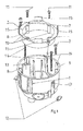
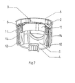
- an installation box for electrical purposes for installation in an opening of a wall with a mouth side open can body 1 is shown.
- a subframe 2 is inserted into the can body 1, which forms the receptacle and holder for a can be installed in the can body 1 installation device and / or a support ring 3 for an installation device.
- the subframe 2 is aligned with its directed to the mouth of the can body 1 end portion in the installation target position so that it lies behind the mouth level of the can body 1, as shown in the drawing figures.
- the subframe 2 is held in the can body 1 in the direction of a bottom 4 of the can body 1 or in the direction of the mouth of the can body 1 adjustable and lockable in different positions, in particular in FIG. 8 and 9 is illustrated.
- the can body 1 of the installation box has a circular cross-section, wherein the can body is formed cylindrically with circumferential mantle.
- the can body 1 On the mouth side, the can body 1 has transverse to its longitudinal extension directed, outwardly projecting abutment surfaces 5, which are preferably formed as a mouth side circumferential collar, as shown in the figures.
- the jacket of the can body 1 and / or the bottom 4 may have breakable or pierceable areas, which serve for the insertion and removal of cables or installation tubes.
- the subframe 2 is designed as a ring body, protrudes from the at the mouth of the can body 1 zugenden end portion a collar 6 transversely outwards.
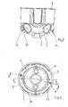
- actuating means 7 are held, which are engaged with adjusting means 8 on the inner surface of the can body 1 and by means of which the adjustment and detection is realized in different positions.
- the adjusting means are 7 cap screws, which are rotatably but axially held immovable. Their threaded shank is in each case screwed into a channel of Stellstofffact 8 on the inner shell of the installation box.
- the screws or adjusting means 7 each take with the subframe 2, so that it is adjusted relative to the can body.
- the head of the cap screws in each case in a formed on the outer casing of the subframe 2 cage 9 can be rotatably held but axially immovable.
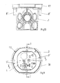
- the installation box is designed as a hollow wall box, on the jacket on and swing-out tabs 12 are arranged, which are actuated by means inserted into channels 13 of the can body 1 tab bolts 14, ie from the pivoted-back position, in which they are behind the circumference of the can jacket , Are movable in a swung-out fastening position and are adjustable in the pivoted position along the jacket in the direction of its mouth.
- protruding webs 15 are additionally formed on its side facing the mouth side parallel to the actuating direction, which form an assembly aid for the installer, so that it can visually recognize the correct distance of the subframe 2 from the outer surface of the wall into which the installation box is inserted ,
- the can body 1 has in the region of its circumferential abutment surface 5 to each other opposite areas or at least one region of predetermined breaking points 16 at which the mouth edge for generating a tangentially directed or formed as a secant flat edge edge is breakable. This serves to achieve the standard installation distance of juxtaposed installation boxes.
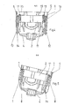
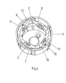
- FIGS. 6 to 8 is in the installation box or the can body 1 whose inner dimension or inner diameter adapted support ring 3 is used, which rests on the mouth of the subframe 2, in particular its collar 6.
- the support ring 3 may be connected in a conventional manner with an installation device, such as a switch, push-button, a socket or other electrical installation equipment.
- an installation device such as a switch, push-button, a socket or other electrical installation equipment.
- the invention makes it possible in a simple manner to align the installed in the can body 1 of the installation box elements by means of the subframe 2 at the desired height so that subsequently a supernatant arrangement relative to the outer surface of the mounting wall is achieved, so that a fixed on this unit cover or aperture in Essentially flush with the surface of the mounting wall.
- the cover or panel may have openings for switches, plugs or the like. she can also be designed as a sensor surface or sensors can be embedded in it.
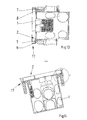
- the a can body 1 with an open at the front or opening opening for installation parts.
- it is a can body 1, which is designed in the form of a conventional flush-mounted box.
- FIG. 19 it is a can body 1, which is designed in the manner of a conventional concrete building box.
- the can body 1 is initially closed by a detachable wall at its mouth. This in the FIG. 19
- the above apparent wall can be in the installation situation, if the part is thus cast in a concrete part, with a suitable tool, such as a knife, be separated, so that the mounting hole is open.
- a front side superior adapter 17 is attached on the can body 1.
- an auxiliary frame 2 is adjustably arranged, so that this as shown in FIG FIGS. 16 and 17 relative to the adapter 17 in the direction of the front side of the can body 1 and away from it is adjustable.
- This subframe 2 is intended to be an installation equipment carrier for the can body 1 built or installed Make installation equipment or keep a support ring for it.
- FIGS. 20 to 22 is also an installation box for electrical purposes shown, which has an open installation opening for installation parts on a front side.
- an adapter 17 ' is arranged, which is intended for installation in an opening of a cavity wall and has means for attachment in the opening.
- the can body 1 is used as intended in the adapter 17 '.
- the can body 1 has an auxiliary frame 2 'at the front, which is fixedly connected to the can body 1, for example, by being screwed.
- the can body 1 together with the subframe 2 'relative to the adapter 17' in the adapter 17 'in and out of this adjustable.
- the subframe 2 ' forms an installation equipment carrier for built-in or installed in the can body 1 installation equipment or he holds a support ring for it.
- the adapter 17,17 'a directed transversely to the longitudinal extent of the can body 1 edge region 18,18' and one of which outside edge opposite the Front side of the can body 1 protruding collar 19,19 'on.
- the subframe 2, 2 ' has a flange edge 20, 20' and collar or collar parts 21, 21 'directed parallel to this edge region 18, 18' and collar 19, 19 '.
- the adapter 17,17' are directed away from the front side actuating means 8 'for adjusting means 7', in which parts of the adjusting means 7 ', in particular the threaded shank of adjusting screws designed as adjusting 7' engage.
- These adjusting means 7 ' are on the subframe 2,2' in regions 23 axially immovable, but rotatably arranged so that by rotation of the adjusting means 7 ', the distance of the subframe 2,2' of the adapter 17,17 'can be adjusted.
- the can body 1 has at the front at an orifice a radially outwardly projecting flange edge 5 '.
- the adapter 17,17 has an end face radially outwardly projecting flange edge 22 or Flanschrandmaschine.
- cover plate can take on different functions, so for example, can be integrated into these electrical switching elements or it can be arranged switches, push-button, sockets or other parts of installation devices.
- the cover plate is preferably releasably attached to a built-in the can body 1 support ring or on a built-in installation device, for example by means of screws or locking means.
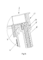
- FIG. 16 and FIG. 21 a situation is shown in which the installation box 1 together with subframe 2,2 'and adapter 17,17' is installed in a wall 24, so that the front side of this unit is flush with the outer surface of the wall concludes.
- FIG. 17 and in FIG. 22 It is shown that on the wall 24 a plaster layer is applied.
- the subframe 2,2' is displaced upwardly by means of the adjusting means 7 'in the drawing, wherein the displacement takes place so far that the ends of the webs 15' flush in the of the Plaster surface 25 spanned plane lie. It is thus an installation allows, which makes it possible to mount without overhang on the plaster surface 25 installation elements, in which case a cover plate can be applied, which only applies their material thickness on the plaster surface 25.
Landscapes
- Engineering & Computer Science (AREA)
- Architecture (AREA)
- Civil Engineering (AREA)
- Structural Engineering (AREA)
- Connection Or Junction Boxes (AREA)
- Connector Housings Or Holding Contact Members (AREA)
Applications Claiming Priority (1)
| Application Number | Priority Date | Filing Date | Title |
|---|---|---|---|
| DE102013110319 | 2013-09-19 |
Publications (3)
| Publication Number | Publication Date |
|---|---|
| EP2852017A2 true EP2852017A2 (fr) | 2015-03-25 |
| EP2852017A3 EP2852017A3 (fr) | 2015-11-04 |
| EP2852017B1 EP2852017B1 (fr) | 2020-04-22 |
Family
ID=51492273
Family Applications (1)
| Application Number | Title | Priority Date | Filing Date |
|---|---|---|---|
| EP14401087.3A Active EP2852017B1 (fr) | 2013-09-19 | 2014-08-06 | Boîtier d'installation à des fins électrotechniques |
Country Status (1)
| Country | Link |
|---|---|
| EP (1) | EP2852017B1 (fr) |
Cited By (6)
| Publication number | Priority date | Publication date | Assignee | Title |
|---|---|---|---|---|
| DE202015104520U1 (de) | 2015-08-26 | 2015-10-02 | Schuf Armaturen Und Apparatebau Gmbh | Tanknotabschlussventil |
| DE102018121693A1 (de) * | 2018-09-05 | 2020-03-05 | Marco Kaussler | Elektroinstallationsdose |
| WO2020052882A1 (fr) * | 2018-09-13 | 2020-03-19 | Schneider Electric Industries Sas | Dispositif d'aide au montage |
| DE102022100530A1 (de) | 2022-01-11 | 2023-07-13 | Schneider Electric Industries Sas | Installationssystem |
| DE102022204895A1 (de) | 2022-05-17 | 2023-11-23 | Adolf Würth GmbH & Co. KG | Installationsdose und Anordnung mit einer Installationsdose |
| EP4290713A3 (fr) * | 2022-06-09 | 2024-02-28 | Corston Ltd | Module |
Citations (3)
| Publication number | Priority date | Publication date | Assignee | Title |
|---|---|---|---|---|
| AT233645B (de) | 1961-12-06 | 1964-05-25 | Busch Jaeger Duerener Metall | Unterputz-Installationsgerät, z. B. Schalter, Taster, Steckdose od. dgl. mit Tragring |
| DE202004002027U1 (de) | 2004-02-10 | 2004-04-15 | Fohs, Winfried | Elektroinstallationsmaterial sowie Einsatzstück für Kabeleinführungen bei Elektroinstallationsmaterial |
| DE10253252B4 (de) | 2002-11-15 | 2004-12-02 | Kaiser Gmbh & Co. Kommanditgesellschaft | Einbaudose |
Family Cites Families (7)
| Publication number | Priority date | Publication date | Assignee | Title |
|---|---|---|---|---|
| DE4431148C2 (de) * | 1994-09-01 | 1997-01-09 | Burtz Gmbh Industrievertretung | Elektro-Installationsdose und Werkzeug zum Einsetzen eines Einsatzes in diese |
| FR2811817B1 (fr) * | 2000-07-13 | 2002-09-06 | Joseph Bagory | Procede de fixation de boites d'encastrement pour composants electriques, telephoniques et similaire dans les parois adossees aux murs exterieurs de maisons ou d'immeubles |
| DE20103739U1 (de) * | 2001-03-03 | 2002-07-11 | Merten GmbH & Co. KG, 51674 Wiehl | Elektrisches Installationsgerät |
| DE10200939B4 (de) * | 2002-01-12 | 2018-11-08 | Merten Gmbh & Co. Kg | Elektrisches Installationsgerät |
| FR2905225B1 (fr) * | 2006-08-23 | 2008-11-07 | Legrand France | Mecanisme d'appareillage a monter par l'arriere d'un support d'appareillage et appareillage electrique comprenant un tel mecanisme. |
| DE202010004188U1 (de) * | 2010-02-12 | 2011-08-08 | Kaiser Gmbh & Co. Kommanditgesellschaft | Installationsteil |
| WO2012074444A1 (fr) * | 2010-11-30 | 2012-06-07 | Schneider Electric Industries Sas | Boîte d'installation dotée de dispositifs d'amarrage |
-
2014
- 2014-08-06 EP EP14401087.3A patent/EP2852017B1/fr active Active
Patent Citations (3)
| Publication number | Priority date | Publication date | Assignee | Title |
|---|---|---|---|---|
| AT233645B (de) | 1961-12-06 | 1964-05-25 | Busch Jaeger Duerener Metall | Unterputz-Installationsgerät, z. B. Schalter, Taster, Steckdose od. dgl. mit Tragring |
| DE10253252B4 (de) | 2002-11-15 | 2004-12-02 | Kaiser Gmbh & Co. Kommanditgesellschaft | Einbaudose |
| DE202004002027U1 (de) | 2004-02-10 | 2004-04-15 | Fohs, Winfried | Elektroinstallationsmaterial sowie Einsatzstück für Kabeleinführungen bei Elektroinstallationsmaterial |
Cited By (7)
| Publication number | Priority date | Publication date | Assignee | Title |
|---|---|---|---|---|
| DE202015104520U1 (de) | 2015-08-26 | 2015-10-02 | Schuf Armaturen Und Apparatebau Gmbh | Tanknotabschlussventil |
| DE102018121693A1 (de) * | 2018-09-05 | 2020-03-05 | Marco Kaussler | Elektroinstallationsdose |
| DE102018121693B4 (de) * | 2018-09-05 | 2021-01-14 | Marco Kaussler | Elektroinstallationsdose |
| WO2020052882A1 (fr) * | 2018-09-13 | 2020-03-19 | Schneider Electric Industries Sas | Dispositif d'aide au montage |
| DE102022100530A1 (de) | 2022-01-11 | 2023-07-13 | Schneider Electric Industries Sas | Installationssystem |
| DE102022204895A1 (de) | 2022-05-17 | 2023-11-23 | Adolf Würth GmbH & Co. KG | Installationsdose und Anordnung mit einer Installationsdose |
| EP4290713A3 (fr) * | 2022-06-09 | 2024-02-28 | Corston Ltd | Module |
Also Published As
| Publication number | Publication date |
|---|---|
| EP2852017A3 (fr) | 2015-11-04 |
| EP2852017B1 (fr) | 2020-04-22 |
Similar Documents
| Publication | Publication Date | Title |
|---|---|---|
| EP2852017A2 (fr) | Boîtier d'installation à des fins électrotechniques | |
| EP1845208B1 (fr) | Dispositif d'installation pour éléments sanitaires | |
| EP1848082B1 (fr) | Système d'installation électronique comprenant un réceptacle pour dispositif avec aire de fixation et aire d'appui pour le dispositif décalées | |
| EP2360800A2 (fr) | Elément d'installation | |
| EP3534476B1 (fr) | Boîte d'installation | |
| DE4241390C2 (de) | Elektrische Hohlwanddose, wie Schalterdose, Abzweigdose o. dgl. | |
| EP2824784A1 (fr) | Boîtier d'installation | |
| DE10200939B4 (de) | Elektrisches Installationsgerät | |
| DE7302905U (de) | Auslaß für Unterflur- und Unterputzinstallationen | |
| CH712235A2 (de) | Installationsdose. | |
| EP3886280B1 (fr) | Système d'installation électrique | |
| CH711488B1 (de) | Einbaubüchsendeckel zum Verschliessen einer Öffnung in einer Einbaubüchse. | |
| CH713572A2 (de) | Installationsdose für elektrische Anschlüsse. | |
| DE10011905C2 (de) | Hohlkörper für die Elektroinstallation | |
| DE102022204895A1 (de) | Installationsdose und Anordnung mit einer Installationsdose | |
| DE202010015515U1 (de) | Anordnung zur Befestigung einer Installationsdose für Elektroinstallationen | |
| DE2926078C2 (fr) | ||
| DE202009014372U1 (de) | Installationsdose für elektrotechnische Zwecke | |
| DE102007039171A1 (de) | Verfahren zur Montage bzw. zum Einbringen eines Hohlkörpers in eine Betonwand oder Betondecke | |
| WO2021185535A1 (fr) | Dispositif de fixation pour un élément sanitaire à accrocher | |
| DE2427973C2 (de) | Hohlwanddose, insbesondere Installationsdose | |
| EP2690729A1 (fr) | Système d'installation électrique et boîtier pour cloison creuse pour l'installation électrique | |
| DE19830139B4 (de) | Schlüsselschaltervorrichtung | |
| DE102009056643A1 (de) | Anordnung zur Befestigung einer Installationsdose für Elektroinstallationen | |
| EP3693521B1 (fr) | Tourillon de montage pour dispositif d'ancrage |
Legal Events
| Date | Code | Title | Description |
|---|---|---|---|
| PUAI | Public reference made under article 153(3) epc to a published international application that has entered the european phase |
Free format text: ORIGINAL CODE: 0009012 |
|
| 17P | Request for examination filed |
Effective date: 20140806 |
|
| AK | Designated contracting states |
Kind code of ref document: A2 Designated state(s): AL AT BE BG CH CY CZ DE DK EE ES FI FR GB GR HR HU IE IS IT LI LT LU LV MC MK MT NL NO PL PT RO RS SE SI SK SM TR |
|
| AX | Request for extension of the european patent |
Extension state: BA ME |
|
| RIC1 | Information provided on ipc code assigned before grant |
Ipc: H02G 3/12 20060101AFI20150610BHEP |
|
| PUAL | Search report despatched |
Free format text: ORIGINAL CODE: 0009013 |
|
| AK | Designated contracting states |
Kind code of ref document: A3 Designated state(s): AL AT BE BG CH CY CZ DE DK EE ES FI FR GB GR HR HU IE IS IT LI LT LU LV MC MK MT NL NO PL PT RO RS SE SI SK SM TR |
|
| AX | Request for extension of the european patent |
Extension state: BA ME |
|
| RIC1 | Information provided on ipc code assigned before grant |
Ipc: H02G 3/12 20060101AFI20151001BHEP |
|
| R17P | Request for examination filed (corrected) |
Effective date: 20160421 |
|
| RBV | Designated contracting states (corrected) |
Designated state(s): AL AT BE BG CH CY CZ DE DK EE ES FI FR GB GR HR HU IE IS IT LI LT LU LV MC MK MT NL NO PL PT RO RS SE SI SK SM TR |
|
| STAA | Information on the status of an ep patent application or granted ep patent |
Free format text: STATUS: EXAMINATION IS IN PROGRESS |
|
| 17Q | First examination report despatched |
Effective date: 20161215 |
|
| GRAP | Despatch of communication of intention to grant a patent |
Free format text: ORIGINAL CODE: EPIDOSNIGR1 |
|
| STAA | Information on the status of an ep patent application or granted ep patent |
Free format text: STATUS: GRANT OF PATENT IS INTENDED |
|
| INTG | Intention to grant announced |
Effective date: 20191216 |
|
| GRAS | Grant fee paid |
Free format text: ORIGINAL CODE: EPIDOSNIGR3 |
|
| GRAA | (expected) grant |
Free format text: ORIGINAL CODE: 0009210 |
|
| STAA | Information on the status of an ep patent application or granted ep patent |
Free format text: STATUS: THE PATENT HAS BEEN GRANTED |
|
| AK | Designated contracting states |
Kind code of ref document: B1 Designated state(s): AL AT BE BG CH CY CZ DE DK EE ES FI FR GB GR HR HU IE IS IT LI LT LU LV MC MK MT NL NO PL PT RO RS SE SI SK SM TR |
|
| REG | Reference to a national code |
Ref country code: GB Ref legal event code: FG4D Free format text: NOT ENGLISH |
|
| REG | Reference to a national code |
Ref country code: CH Ref legal event code: EP |
|
| REG | Reference to a national code |
Ref country code: DE Ref legal event code: R096 Ref document number: 502014014032 Country of ref document: DE |
|
| REG | Reference to a national code |
Ref country code: IE Ref legal event code: FG4D Free format text: LANGUAGE OF EP DOCUMENT: GERMAN |
|
| REG | Reference to a national code |
Ref country code: AT Ref legal event code: REF Ref document number: 1261405 Country of ref document: AT Kind code of ref document: T Effective date: 20200515 |
|
| REG | Reference to a national code |
Ref country code: NL Ref legal event code: FP |
|
| REG | Reference to a national code |
Ref country code: LT Ref legal event code: MG4D |
|
| PG25 | Lapsed in a contracting state [announced via postgrant information from national office to epo] |
Ref country code: GR Free format text: LAPSE BECAUSE OF FAILURE TO SUBMIT A TRANSLATION OF THE DESCRIPTION OR TO PAY THE FEE WITHIN THE PRESCRIBED TIME-LIMIT Effective date: 20200723 Ref country code: NO Free format text: LAPSE BECAUSE OF FAILURE TO SUBMIT A TRANSLATION OF THE DESCRIPTION OR TO PAY THE FEE WITHIN THE PRESCRIBED TIME-LIMIT Effective date: 20200722 Ref country code: FI Free format text: LAPSE BECAUSE OF FAILURE TO SUBMIT A TRANSLATION OF THE DESCRIPTION OR TO PAY THE FEE WITHIN THE PRESCRIBED TIME-LIMIT Effective date: 20200422 Ref country code: SE Free format text: LAPSE BECAUSE OF FAILURE TO SUBMIT A TRANSLATION OF THE DESCRIPTION OR TO PAY THE FEE WITHIN THE PRESCRIBED TIME-LIMIT Effective date: 20200422 Ref country code: IS Free format text: LAPSE BECAUSE OF FAILURE TO SUBMIT A TRANSLATION OF THE DESCRIPTION OR TO PAY THE FEE WITHIN THE PRESCRIBED TIME-LIMIT Effective date: 20200822 Ref country code: PT Free format text: LAPSE BECAUSE OF FAILURE TO SUBMIT A TRANSLATION OF THE DESCRIPTION OR TO PAY THE FEE WITHIN THE PRESCRIBED TIME-LIMIT Effective date: 20200824 Ref country code: LT Free format text: LAPSE BECAUSE OF FAILURE TO SUBMIT A TRANSLATION OF THE DESCRIPTION OR TO PAY THE FEE WITHIN THE PRESCRIBED TIME-LIMIT Effective date: 20200422 |
|
| PG25 | Lapsed in a contracting state [announced via postgrant information from national office to epo] |
Ref country code: HR Free format text: LAPSE BECAUSE OF FAILURE TO SUBMIT A TRANSLATION OF THE DESCRIPTION OR TO PAY THE FEE WITHIN THE PRESCRIBED TIME-LIMIT Effective date: 20200422 Ref country code: BG Free format text: LAPSE BECAUSE OF FAILURE TO SUBMIT A TRANSLATION OF THE DESCRIPTION OR TO PAY THE FEE WITHIN THE PRESCRIBED TIME-LIMIT Effective date: 20200722 Ref country code: LV Free format text: LAPSE BECAUSE OF FAILURE TO SUBMIT A TRANSLATION OF THE DESCRIPTION OR TO PAY THE FEE WITHIN THE PRESCRIBED TIME-LIMIT Effective date: 20200422 Ref country code: RS Free format text: LAPSE BECAUSE OF FAILURE TO SUBMIT A TRANSLATION OF THE DESCRIPTION OR TO PAY THE FEE WITHIN THE PRESCRIBED TIME-LIMIT Effective date: 20200422 |
|
| PG25 | Lapsed in a contracting state [announced via postgrant information from national office to epo] |
Ref country code: AL Free format text: LAPSE BECAUSE OF FAILURE TO SUBMIT A TRANSLATION OF THE DESCRIPTION OR TO PAY THE FEE WITHIN THE PRESCRIBED TIME-LIMIT Effective date: 20200422 |
|
| REG | Reference to a national code |
Ref country code: DE Ref legal event code: R097 Ref document number: 502014014032 Country of ref document: DE |
|
| PG25 | Lapsed in a contracting state [announced via postgrant information from national office to epo] |
Ref country code: CZ Free format text: LAPSE BECAUSE OF FAILURE TO SUBMIT A TRANSLATION OF THE DESCRIPTION OR TO PAY THE FEE WITHIN THE PRESCRIBED TIME-LIMIT Effective date: 20200422 Ref country code: RO Free format text: LAPSE BECAUSE OF FAILURE TO SUBMIT A TRANSLATION OF THE DESCRIPTION OR TO PAY THE FEE WITHIN THE PRESCRIBED TIME-LIMIT Effective date: 20200422 Ref country code: ES Free format text: LAPSE BECAUSE OF FAILURE TO SUBMIT A TRANSLATION OF THE DESCRIPTION OR TO PAY THE FEE WITHIN THE PRESCRIBED TIME-LIMIT Effective date: 20200422 Ref country code: DK Free format text: LAPSE BECAUSE OF FAILURE TO SUBMIT A TRANSLATION OF THE DESCRIPTION OR TO PAY THE FEE WITHIN THE PRESCRIBED TIME-LIMIT Effective date: 20200422 Ref country code: EE Free format text: LAPSE BECAUSE OF FAILURE TO SUBMIT A TRANSLATION OF THE DESCRIPTION OR TO PAY THE FEE WITHIN THE PRESCRIBED TIME-LIMIT Effective date: 20200422 Ref country code: IT Free format text: LAPSE BECAUSE OF FAILURE TO SUBMIT A TRANSLATION OF THE DESCRIPTION OR TO PAY THE FEE WITHIN THE PRESCRIBED TIME-LIMIT Effective date: 20200422 Ref country code: SM Free format text: LAPSE BECAUSE OF FAILURE TO SUBMIT A TRANSLATION OF THE DESCRIPTION OR TO PAY THE FEE WITHIN THE PRESCRIBED TIME-LIMIT Effective date: 20200422 |
|
| PG25 | Lapsed in a contracting state [announced via postgrant information from national office to epo] |
Ref country code: PL Free format text: LAPSE BECAUSE OF FAILURE TO SUBMIT A TRANSLATION OF THE DESCRIPTION OR TO PAY THE FEE WITHIN THE PRESCRIBED TIME-LIMIT Effective date: 20200422 Ref country code: SK Free format text: LAPSE BECAUSE OF FAILURE TO SUBMIT A TRANSLATION OF THE DESCRIPTION OR TO PAY THE FEE WITHIN THE PRESCRIBED TIME-LIMIT Effective date: 20200422 |
|
| PLBE | No opposition filed within time limit |
Free format text: ORIGINAL CODE: 0009261 |
|
| STAA | Information on the status of an ep patent application or granted ep patent |
Free format text: STATUS: NO OPPOSITION FILED WITHIN TIME LIMIT |
|
| 26N | No opposition filed |
Effective date: 20210125 |
|
| PG25 | Lapsed in a contracting state [announced via postgrant information from national office to epo] |
Ref country code: MC Free format text: LAPSE BECAUSE OF FAILURE TO SUBMIT A TRANSLATION OF THE DESCRIPTION OR TO PAY THE FEE WITHIN THE PRESCRIBED TIME-LIMIT Effective date: 20200422 |
|
| REG | Reference to a national code |
Ref country code: CH Ref legal event code: PL |
|
| GBPC | Gb: european patent ceased through non-payment of renewal fee |
Effective date: 20200806 |
|
| PG25 | Lapsed in a contracting state [announced via postgrant information from national office to epo] |
Ref country code: LI Free format text: LAPSE BECAUSE OF NON-PAYMENT OF DUE FEES Effective date: 20200831 Ref country code: CH Free format text: LAPSE BECAUSE OF NON-PAYMENT OF DUE FEES Effective date: 20200831 Ref country code: LU Free format text: LAPSE BECAUSE OF NON-PAYMENT OF DUE FEES Effective date: 20200806 |
|
| REG | Reference to a national code |
Ref country code: BE Ref legal event code: MM Effective date: 20200831 |
|
| PG25 | Lapsed in a contracting state [announced via postgrant information from national office to epo] |
Ref country code: SI Free format text: LAPSE BECAUSE OF FAILURE TO SUBMIT A TRANSLATION OF THE DESCRIPTION OR TO PAY THE FEE WITHIN THE PRESCRIBED TIME-LIMIT Effective date: 20200422 |
|
| PG25 | Lapsed in a contracting state [announced via postgrant information from national office to epo] |
Ref country code: FR Free format text: LAPSE BECAUSE OF NON-PAYMENT OF DUE FEES Effective date: 20200831 |
|
| PG25 | Lapsed in a contracting state [announced via postgrant information from national office to epo] |
Ref country code: IE Free format text: LAPSE BECAUSE OF NON-PAYMENT OF DUE FEES Effective date: 20200806 Ref country code: GB Free format text: LAPSE BECAUSE OF NON-PAYMENT OF DUE FEES Effective date: 20200806 Ref country code: BE Free format text: LAPSE BECAUSE OF NON-PAYMENT OF DUE FEES Effective date: 20200831 |
|
| PG25 | Lapsed in a contracting state [announced via postgrant information from national office to epo] |
Ref country code: TR Free format text: LAPSE BECAUSE OF FAILURE TO SUBMIT A TRANSLATION OF THE DESCRIPTION OR TO PAY THE FEE WITHIN THE PRESCRIBED TIME-LIMIT Effective date: 20200422 Ref country code: MT Free format text: LAPSE BECAUSE OF FAILURE TO SUBMIT A TRANSLATION OF THE DESCRIPTION OR TO PAY THE FEE WITHIN THE PRESCRIBED TIME-LIMIT Effective date: 20200422 Ref country code: CY Free format text: LAPSE BECAUSE OF FAILURE TO SUBMIT A TRANSLATION OF THE DESCRIPTION OR TO PAY THE FEE WITHIN THE PRESCRIBED TIME-LIMIT Effective date: 20200422 |
|
| PG25 | Lapsed in a contracting state [announced via postgrant information from national office to epo] |
Ref country code: MK Free format text: LAPSE BECAUSE OF FAILURE TO SUBMIT A TRANSLATION OF THE DESCRIPTION OR TO PAY THE FEE WITHIN THE PRESCRIBED TIME-LIMIT Effective date: 20200422 |
|
| PGFP | Annual fee paid to national office [announced via postgrant information from national office to epo] |
Ref country code: NL Payment date: 20250821 Year of fee payment: 12 |
|
| PGFP | Annual fee paid to national office [announced via postgrant information from national office to epo] |
Ref country code: AT Payment date: 20250822 Year of fee payment: 12 |
|
| PGFP | Annual fee paid to national office [announced via postgrant information from national office to epo] |
Ref country code: DE Payment date: 20251028 Year of fee payment: 12 |
|
| REG | Reference to a national code |
Ref country code: DE Ref legal event code: R082 Ref document number: 502014014032 Country of ref document: DE Representative=s name: KOECHLING, MARIETTA, M.SC B.ENG., DE |