EP2852279B1 - Agencement de brossage d'animal et procédé de fonctionnement d'un agencement de brossage d'animal - Google Patents
Agencement de brossage d'animal et procédé de fonctionnement d'un agencement de brossage d'animal Download PDFInfo
- Publication number
- EP2852279B1 EP2852279B1 EP13714030.7A EP13714030A EP2852279B1 EP 2852279 B1 EP2852279 B1 EP 2852279B1 EP 13714030 A EP13714030 A EP 13714030A EP 2852279 B1 EP2852279 B1 EP 2852279B1
- Authority
- EP
- European Patent Office
- Prior art keywords
- brush
- electric motor
- arrangement
- animal brushing
- brushing arrangement
- Prior art date
- Legal status (The legal status is an assumption and is not a legal conclusion. Google has not performed a legal analysis and makes no representation as to the accuracy of the status listed.)
- Active
Links
Images

Classifications
-
- G—PHYSICS
- G01—MEASURING; TESTING
- G01P—MEASURING LINEAR OR ANGULAR SPEED, ACCELERATION, DECELERATION, OR SHOCK; INDICATING PRESENCE, ABSENCE, OR DIRECTION, OF MOVEMENT
- G01P3/00—Measuring linear or angular speed; Measuring differences of linear or angular speeds
- G01P3/42—Devices characterised by the use of electric or magnetic means
- G01P3/44—Devices characterised by the use of electric or magnetic means for measuring angular speed
- G01P3/48—Devices characterised by the use of electric or magnetic means for measuring angular speed by measuring frequency of generated current or voltage
- G01P3/481—Devices characterised by the use of electric or magnetic means for measuring angular speed by measuring frequency of generated current or voltage of pulse signals
- G01P3/486—Devices characterised by the use of electric or magnetic means for measuring angular speed by measuring frequency of generated current or voltage of pulse signals delivered by photo-electric detectors
-
- A—HUMAN NECESSITIES
- A01—AGRICULTURE; FORESTRY; ANIMAL HUSBANDRY; HUNTING; TRAPPING; FISHING
- A01K—ANIMAL HUSBANDRY; AVICULTURE; APICULTURE; PISCICULTURE; FISHING; REARING OR BREEDING ANIMALS, NOT OTHERWISE PROVIDED FOR; NEW BREEDS OF ANIMALS
- A01K13/00—Devices for grooming or caring of animals, e.g. curry-combs; Fetlock rings; Tail-holders; Devices for preventing crib-biting; Washing devices; Protection against weather conditions or insects
- A01K13/002—Curry combs; Brushes
-
- A—HUMAN NECESSITIES
- A01—AGRICULTURE; FORESTRY; ANIMAL HUSBANDRY; HUNTING; TRAPPING; FISHING
- A01K—ANIMAL HUSBANDRY; AVICULTURE; APICULTURE; PISCICULTURE; FISHING; REARING OR BREEDING ANIMALS, NOT OTHERWISE PROVIDED FOR; NEW BREEDS OF ANIMALS
- A01K13/00—Devices for grooming or caring of animals, e.g. curry-combs; Fetlock rings; Tail-holders; Devices for preventing crib-biting; Washing devices; Protection against weather conditions or insects
- A01K13/004—Rubbing posts
-
- A—HUMAN NECESSITIES
- A46—BRUSHWARE
- A46B—BRUSHES
- A46B13/00—Brushes with driven brush bodies or carriers
- A46B13/001—Cylindrical or annular brush bodies
-
- A—HUMAN NECESSITIES
- A46—BRUSHWARE
- A46B—BRUSHES
- A46B13/00—Brushes with driven brush bodies or carriers
- A46B13/02—Brushes with driven brush bodies or carriers power-driven carriers
-
- G—PHYSICS
- G01—MEASURING; TESTING
- G01P—MEASURING LINEAR OR ANGULAR SPEED, ACCELERATION, DECELERATION, OR SHOCK; INDICATING PRESENCE, ABSENCE, OR DIRECTION, OF MOVEMENT
- G01P3/00—Measuring linear or angular speed; Measuring differences of linear or angular speeds
- G01P3/42—Devices characterised by the use of electric or magnetic means
- G01P3/44—Devices characterised by the use of electric or magnetic means for measuring angular speed
- G01P3/48—Devices characterised by the use of electric or magnetic means for measuring angular speed by measuring frequency of generated current or voltage
- G01P3/481—Devices characterised by the use of electric or magnetic means for measuring angular speed by measuring frequency of generated current or voltage of pulse signals
- G01P3/487—Devices characterised by the use of electric or magnetic means for measuring angular speed by measuring frequency of generated current or voltage of pulse signals delivered by rotating magnets
Definitions
- the present invention relates to an animal brushing arrangement and a method of operating an animal brushing arrangement.
- Some animal brushing arrangements for brushing larger animals such as livestock, horses, pigs, etc., are mounted to a support structure and provided with a rotating brush which is driven by an electric motor, either directly or via a gear box.
- the brush is provided with bristles which, when the brush is rotated, interact with the fur and skin of an animal. The animal is thus brushed, scratched and/or groomed by the rotating brush.
- the rotating brush is suspended at one end from a brush carrying arrangement.
- the brush carrying arrangement comprises one or more parts, which allow the brush to swing back and forth in at least one plane.
- the brush may thus be moved by an animal when leaning against the brush to reach different parts of the body of the animal.
- Such animal brushing arrangements may be provided with the electric motor attached to the brush carrying arrangement above the rotating brush, as disclosed in e.g. EP 1487258 , EP 1665927 and WO 2012/005654 .
- such an animal brushing arrangement may be provided with the electric motor arranged inside the brush, as disclosed e.g. in EP 2422617 .
- EP 2271203 and EP 2422617 disclose the use of sensors or switches for controlling brush rotation.
- EP 2271203 discloses a sensor arranged to detect, by means of markings on a wall mounted mounting plate, a direction of pivoting of a casing of the brush. The alternative use of an inclinometer or inclinodetector is also mentioned. A direction of rotation of the brush is based on the detection.
- EP 2422617 discloses a switch mounted on a portion of a carrier of the brush.
- the switch is actuated by an angle bar arranged on a further portion of the carrier, when the brush and the further portion perform a pivoting motion in relation to the switch.
- WO 2009/131439 discloses the use of rotation meters to detect in which direction from vertical a brush has been swivelled by a cow.
- An object of the present invention is to provide an animal brushing arrangement comprising an alternative arrangement for triggering a start of rotation of a brush of the brushing arrangement, which triggering may be achieved also by animals too small to lift the brush.
- an animal brushing arrangement for attaching to a support structure.
- the animal brushing arrangement comprises a support part arranged to be attached to the support structure, a brush, and an electric motor arranged to rotate the brush about a rotation axis.
- the brushing arrangement further comprises a rotation sensor arranged to interact with the brush.
- the brush is also rotatable about its rotation axis by an externally applied force.
- the rotation sensor is adapted to sense a rotational movement of the brush about its rotation axis caused by the externally applied force.
- a rotation sensor for sensing the rotational movement caused by the externally applied force, i.e. an externally induced rotation of the brush
- an animal rotating the brush about its axis triggers the rotation sensor which may cause the electric motor to start rotating the brush.
- the above mentioned object is achieved. Even a small animal such as a calf or a goat may be able to apply the external force required to provoke the electric motor to rotate the brush.
- the animal brushing arrangement may be attached to a supporting structure such as post or a wall.
- the animal brushing arrangement may be arranged in an animal housing, such as a barn or a stable.
- the animal brushing arrangement may be arranged in other locations, such as outdoors e.g. in a pasture.
- a control system may be provided for controlling the animal brushing arrangement.
- the control system may be adapted to control the electric motor as such, as well as peripheral functions such as: starting and stopping the electrical motor, monitoring electric motor current to prevent overload of the electric motor, provide a timer function, set direction of rotation of the electric motor, etc.
- the control system may comprise one single control unit or it may comprise two or more control units forming a distributed system.
- the rotation sensor may interact directly with the brush sensing the rotation of the brush about its rotation axis. Alternatively, the rotation sensor may interact indirectly with the brush.
- the brush may suitably be a substantially rotation symmetrical brush, having for instance a cylindrical, cigar, or hourglass shape.
- the brush may comprise an inner portion and bristles, the bristles being attached to the inner portion.
- the rotation sensor may comprise a pulse generator arranged to generate electrical pulses when the brush is rotated about its rotation axis.
- the electrical pulses may be utilized by a control system of the brushing arrangement to start the electric motor and thus a rotation of the brush about its rotation axis.
- the electric motor may comprise the pulse generator. This may form a convenient and straight forward manner of indirect sensing the rotation of the brush.
- Some types of electrical motors are provided with a sensor arrangement for controlling the rotation of the electric motor.
- Such a sensor arrangement may comprise or form a pulse generator.
- Such a sensor arrangement is connected to a motor controller which utilizes the generated pulses from the sensor arrangement for controlling the rotation of the electric motor. It has been realized by the inventor that a sensor arrangement of the electric motor, the sensor arrangement comprising a pulse generator, may be utilized for triggering the electric motor to rotate the brush.
- Pulses are generated by the pulse generator of the sensor arrangement when the electric motor is rotated by means of control signals from the motor controller as well as when the electric motor is rotated by and external momentum applied to a drive shaft of the electric motor.
- the momentum is applied by the externally induced rotation of the brush, i.e. a rotation of the brush caused by the externally applied force.
- the animal brushing arrangement may comprise a control system, wherein the pulse generator is connected to the control system, and wherein the control system may be adapted to start the electric motor in response to a predetermined number of electrical pulses from the pulse generator being received by the control system. Due to the requirement for a predetermined number of electrical pulses, accidental starting of the rotating of the brush may be avoided, i.e. rotation not caused by an animal such as rotation caused by air movement will not start the electric motor.
- the control system for controlling the animal brushing arrangement may be adapted to control the electric motor as such, as well as peripheral functions.
- the control system may comprise one single control unit or it may comprise two or more control units forming a distributed control system.
- the predetermined number of electrical pulses corresponds to a rotational movement of the brush about its rotation axis of at least 1 degree.
- the electric motor may be a brushless motor and the rotation sensor may be a sensor arrangement adapted for controlling the brushless motor.
- the electric motor may be adapted for an operating voltage of 24 Volts. In this manner a voltage provided from the control system to the electric motor may not exceed 24 Volts. A low voltage system is thus provided, which does not require the same precautions as a higher voltage system does.
- a transmission may be arranged between an output shaft of the electric motor and the brush.
- the rotation sensor may comprise a Hall Effect sensor.
- the Hall Effect sensor may generate electrical pulses or an oscillating electrical signal.
- the oscillating electrical signal is herein considered to comprise electrical pulses.
- the oscillating electrical signal may be interpreted as electrical pulses by a control system of the animal brushing arrangement.
- the rotation sensor may comprise a photo sensor.
- the photo sensor may generate electrical pulses.
- the support part may comprise a support arm and the animal brushing arrangement may comprise a hinge arrangement attached to the support arm.
- the brush may be suspended from the hinge arrangement such that the brush may be pivoted in a substantially vertical plane about an axis of the hinge arrangement.
- the animal brushing arrangement may comprise a brush frame attached to the hinge arrangement.
- the electric motor may be attached to the brush frame inside the brush.
- the brush may be arranged to rotate about the brush frame and the electric motor. In this manner the electric motor may be protectively arranged inside the brush. A transfer of the rotation of the electric motor to the brush, and vice versa, may easily be achieved.
- the above-mentioned object is achieved by a method of operating an animal brushing arrangement.
- the animal brushing arrangement comprising a support part arranged to be attached to a support structure, a brush having a rotation axis, an electric motor, and a rotation sensor arranged to interact with the brush.
- the method comprises, in the following order:
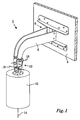
- Fig. 1 illustrates an animal brushing arrangement 2 according to embodiments for attaching to a support structure, such as a wall 4.
- the animal brushing arrangement 2 comprises a support part 6 arranged to be attached to the support structure 4.
- the support part 6 comprises a support arm 8.
- a hinge arrangement is 10 attached to the support arm 8 and a brush 12 is suspended from the hinge arrangement 10.
- the brush 12 may have a cylindrical shape with a diameter of approximately 260 mm and a height of approximately 370 mm.
- the brush 12 may naturally have a different shape and different size.
- An electric motor is arranged inside the brush to rotate the brush 12 about a rotation axis 14.
- the hinge arrangement 10 comprises two substantially orthogonal axes 16,18.
- the brush 12 may thus be pivoted within in a space substantially forming a half sphere.
- the hinge arrangement 10 may comprise only one axis, in which case the brush 12 may be pivoted in a vertical plane.
- the support arm 8 may extend approximately 600 mm outwardly from the support structure.
- the brush 12 is adapted to be rotated about its rotation axis 14 by an externally applied force.
- An animal desiring to be brushed by the brushing arrangement 2 may lean against the brush 12, thus subjecting the brush 12 to an externally applied force which causes the brush 12 to rotate about its rotation axis 14.
- a rotation sensor is arranged to interact with the brush 12. The rotation sensor is adapted to sense a rotational movement induced by the externally applied force.
- a control system is provided for controlling the animal brushing arrangement 2.
- a rotational movement sensed by the rotation sensor prompts the control system to start the electrical motor to rotate the brush 12 about its rotation axis 14.
- the rotation speed of the brush 12 may be about 50 rpm, which may entail a peripheral speed of the brush of about 42 metres/minute.
- Fig. 2 illustrates the animal brushing arrangement 2 of Fig. 1 with the brush 12 removed.
- a brush frame 20 is attached to the hinge arrangement 10.
- an electric motor 22 is arranged inside the brush.
- the electric motor 22 is attached to the brush frame 20.
- the brush is arranged to rotate about the brush frame 20 and the electric motor 22. Accordingly, the brush frame 20 is not actively rotated in relation to the hinge arrangement 10.
- the brush frame 20 extends about the rotation axis 14 of the brush.
- the brush frame 20 is elongated and extends along the rotation axis 14.
- a transmission 24 is arranged between an output shaft of the electric motor 22 and the brush.
- the transmission may comprise a planetary gearing, e.g. as provided by the company IMS Gear.
- the transmission may have a transmission ratio of between 20:1 and 35:1.
- the brush is supported by a first support member 26 arranged at a first end 28 of the brush frame 20 and by a second support member 30 at a second end 32 of the brush frame 20.
- the brush is attached to an output shaft of the transmission 24 at the first end 28 of the brush frame 20 by means of the first support member 26.
- the second support member 30 is rotatably supported by at least one bearing arranged between the second support member 30 and the brush frame 20. The weight of the brush is thus substantially supported by the brush frame 20 and the hinge arrangement 10, and not by the output shaft of the transmission 24.
- the electric motor 22 comprises a sensor arrangement 34.
- the sensor arrangement 34 is utilized for controlling the electric motor. Furthermore, the sensor arrangement 34 forms the rotation sensor arranged to interact with the brush, which rotation sensor is adapted to sense a rotational movement induced by an externally applied force to the brush.
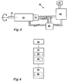
- Fig. 3 illustrates an electric motor 22 and a control system 36 for an animal brushing arrangement according to embodiments, such as the animal brushing arrangement 2 described in connection with Figs. 1 and 2 .
- the electric motor 22 is arranged to rotate a brush of the animal brushing arrangement.
- the electric motor 22 comprises an output shaft 38 and a sensor arrangement 34.
- the control system 36 comprises a motor controller 40, a control device 42, and a timer 44.
- the motor controller 40 is arranged to control the electric motor 22 on a basic level. From the sensor arrangement 34 signals relating to the rotation of the electric motor 22 are sent to the motor controller 40, which signals are utilized by the motor controller 40 to power the electric motor 22.
- the timer 44 counts down a specific period of time, e.g. 1 minute.
- the control device 42 is set to control the operation of the brushing arrangement 2. Signals from the sensor arrangement 34 are also received by the control device 42. Accordingly, when the brush is rotated by an animal the rotation is transferred to electric motor 22, and the sensor arrangement 34 sends out a signal in the form of electrical pulses. Thus, the sensor arrangement 34 forms a rotation sensor of the animal brushing arrangement.
- the control device 42 receives the signal from the sensor arrangement 34 and sends a start signal to the motor controller 40. At the same time the control device 42 starts the timer 44.
- the motor controller 40 controls the rotation of the electric motor 22 as set out above until a stop signal is received from the control device 42.
- the control device 42 is alerted by the timer 44 when it has been counted down.
- control device 42 sends the stop signal to the motor controller 40. If the animal desires to be further brushed, the animal starts another period of brushing in the same manner as described above. If no animal is present, the brush remains stopped until the brush is again rotated by an animal.
- the sensor arrangement 34 may comprise at least one Hall Effect sensor.
- the rotation sensor may comprise a photo sensor.
- the photo sensor may generate electrical pulses correlating with a rotation of the electric motor 22.
- a rotation sensor in the form of a pulse generator is provided, i.e. the electric motor 22 comprises the pulse generator. Electrical pulses are generated when the brush is rotated.
- the electric motor 22 may be a brushless motor adapted for an operating voltage of 24 Volts, such as the MB057GA412 by the company Exmek.
- the motor controller 40 may be a brushless motor controller, such as the EM-206 brushless motor controller with Hall Effect sensor input by the company Electromen Oy, Finland.
- the control system 36 may be adapted to start the electric motor 22 in response to a predetermined number of electrical pulses from the sensor arrangement 34.
- the predetermined number of electrical pulses may correspond to a rotational movement of the brush about its rotation axis of at least 1 degree.
- Accidental starting of the electrical motor 24 and the rotation of the brush may thus be avoided.
- it should be ensured when stopping the electric motor 22 that the electric motor 22 stops within the rotational movement of the brush corresponding to the predetermined number of electrical pulses.
- the motor controller 40 may actively stop the electric motor 22, i.e. not only shut down power to the electric motor 22 but instead control power to the electric motor 22 to promote a retardation of the rotation of the electric motor 22.
- the control device 42 may provide a rotation direction signal to the motor controller 40. In response to the rotation direction signal the motor controller 40 rotates the electric motor 22 either in a clockwise or a counter clockwise direction.
- the control device 42 may e.g. be set to alternate the rotation direction of the electric motor 22 each time the electric motor is started, or to rotate the electric motor 2 in a direction corresponding to the direction of rotation to which an animal subjects the brush.
- Fig. 4 illustrates a method of operating an animal brushing arrangement.
- the animal brushing arrangement comprises a support part arranged to be attached to a support structure, a brush having a rotation axis, an electric motor, and a rotation sensor arranged to interact with the brush.
- the animal brushing arrangement may be an animal brushing arrangement 2 as described in connection with Figs. 1 and 2 , and may comprise a control system 36 as described in connection with Fig. 3 .
- the method comprises, in the following order:
- the sensing 52 may comprise:
- the sensing 52 may comprise:
- the predetermined number of electrical pulses may correspond to a rotational movement of the brush about its rotation axis of at least 1 degree.
- Example embodiments described above may be combined as understood by a person skilled in the art. It is also understood by those skilled in the art that the rotation sensor may directly interact with the brush, e.g. a wheel of the rotation sensor may abut against a portion of the brush and may be rotated by the brush as the brush is rotated by an externally applied force.
- a wheel of the rotation sensor may abut against a portion of the brush and may be rotated by the brush as the brush is rotated by an externally applied force.
- control system 36 described in connection with Fig. 3 may comprise one single control unit performing the above-mentioned control of the animal brushing arrangement and the electric motor 22.
- control system 36 may comprise a different number of components than the three components described in connection with Fig. 3 .
Landscapes
- Life Sciences & Earth Sciences (AREA)
- Environmental Sciences (AREA)
- Zoology (AREA)
- Animal Husbandry (AREA)
- Biodiversity & Conservation Biology (AREA)
- Physics & Mathematics (AREA)
- General Physics & Mathematics (AREA)
- Brushes (AREA)
Claims (15)
- Agencement de brossage d'animal (2) destiné à être relié à une structure de support, l'agencement de brossage d'animal (2) comprenant une partie de support (6) agencée pour être reliée à la structure de support, une brosse (12) et un moteur électrique (22) agencé pour faire tourner la brosse (12) sur un axe de rotation (14), l'agencement de brossage d'animal (2) comprenant un capteur de rotation (34) agencé pour interagir avec la brosse (12), caractérisé en ce que la brosse (12) est également rotative sur son axe de rotation (14) par une force appliquée de l'extérieur, et le capteur de rotation (34) est adapté pour détecter un mouvement de rotation de la brosse (12) sur son axe de rotation (14) provoqué par la force appliquée de l'extérieur.
- Agencement de brossage d'animal (2) selon la revendication 1, dans lequel le capteur de rotation (34) comprend un générateur d'impulsions agencé pour générer des impulsions électriques quand la brosse (12) est tournée sur son axe de rotation (14).
- Agencement de brossage d'animal (2) selon la revendication 2, dans lequel le moteur électrique (22) comprend le générateur d'impulsions.
- Agencement de brossage d'animal (2) selon l'une quelconque des revendications 2 et 3, comprenant un système de commande (36), le générateur d'impulsions étant raccordé au système de commande (36) et le système de commande (36) étant adapté pour démarrer le moteur électrique (22) en réaction à un nombre prédéfini d'impulsions électriques du générateur d'impulsions qui est reçu par le système de commande (36).
- Agencement de brossage d'animal (2) selon la revendication 4, dans lequel le nombre prédéfini d'impulsions électriques correspond à un mouvement de rotation de la brosse (12) sur son axe de rotation (14) d'au moins 1 degré.
- Agencement de brossage d'animal (2) selon l'une quelconque des revendications précédentes, dans lequel le moteur électrique (22) est un moteur sans balai et le capteur de rotation (34) est un agencement de capteur (34) adapté pour commander le moteur sans balai.
- Agencement de brossage d'animal (2) selon l'une quelconque des revendications précédentes, dans lequel le moteur électrique (22) est adapté pour une tension de service de 24 volts.
- Agencement de brossage d'animal (2) selon l'une quelconque des revendications précédentes, dans lequel une transmission (24) est agencée entre un arbre de sortie du moteur électrique (22) et la brosse (12).
- Agencement de brossage d'animal (2) selon l'une quelconque des revendications précédentes, dans lequel le capteur de rotation (34) comprend un capteur photoélectrique.
- Agencement de brossage d'animal (2) selon l'une quelconque des revendications précédentes, dans lequel la partie de support (6) comprend un bras de support (8) et l'agencement de brossage d'animal (2) comprend un agencement de charnières (10) relié au bras de support (8).
- Agencement de brossage d'animal (2) selon la revendication 10, comprenant un cadre (20) de brosse (12) relié à l'agencement de charnières (10), le moteur électrique (22) étant relié au cadre (20) de brosse à l'intérieur de la brosse (12), et la brosse (12) étant agencée pour tourner sur le cadre (20) de brosse et le moteur électrique (22).
- Procédé de fonctionnement d'un agencement de brossage d'animal (2), l'agencement de brossage d'animal comprenant une partie de support agencée pour être reliée à une structure de support, une brosse présentant un axe de rotation, un moteur électrique et un capteur de rotation agencé pour interagir avec la brosse, le procédé comprenant dans l'ordre suivant :la provocation (50) d'un mouvement de rotation de la brosse sur son axe de rotation par une force appliquée de l'extérieur,la détection (52) au moyen du capteur de rotation du mouvement de rotation de la brosse sur son axe de rotation, etl'utilisation (54) du moteur électrique pour faire tourner la brosse sur son axe de rotation.
- Procédé selon la revendication 12, dans lequel le capteur de rotation comprend un générateur d'impulsions, et dans lequel la détection (52) comprend :la génération (56) d'impulsions électriques.
- Procédé selon la revendication 13, dans lequel l'agencement de brossage d'animal comprend un système de commande et le générateur d'impulsions est raccordé au système de commande, et dans lequel la détection (52) comprend :la réception (58) par le système de commande d'impulsions électriques du générateur d'impulsions, et dans lequel l'utilisation (54) comprend :le démarrage (60) du moteur électrique en réaction à un nombre prédéfini d'impulsions électriques qui est reçu par le système de commande.
- Procédé selon la revendication 14, dans lequel le nombre prédéfini d'impulsions électriques correspond à un mouvement de rotation de la brosse sur son axe de rotation d'au moins 1 degré.
Applications Claiming Priority (3)
| Application Number | Priority Date | Filing Date | Title |
|---|---|---|---|
| US201261650527P | 2012-05-23 | 2012-05-23 | |
| SE1250525A SE537565C2 (sv) | 2012-05-23 | 2012-05-23 | Djurborstningsanordning och förfarande för drift av en djurborstningsanordning |
| PCT/SE2013/050231 WO2013176596A1 (fr) | 2012-05-23 | 2013-03-13 | Agencement de brossage d'animal et procédé de fonctionnement d'un agencement de brossage d'animal |
Publications (2)
| Publication Number | Publication Date |
|---|---|
| EP2852279A1 EP2852279A1 (fr) | 2015-04-01 |
| EP2852279B1 true EP2852279B1 (fr) | 2016-06-08 |
Family
ID=49624164
Family Applications (1)
| Application Number | Title | Priority Date | Filing Date |
|---|---|---|---|
| EP13714030.7A Active EP2852279B1 (fr) | 2012-05-23 | 2013-03-13 | Agencement de brossage d'animal et procédé de fonctionnement d'un agencement de brossage d'animal |
Country Status (14)
| Country | Link |
|---|---|
| US (1) | US9565834B2 (fr) |
| EP (1) | EP2852279B1 (fr) |
| JP (1) | JP6053228B2 (fr) |
| KR (1) | KR102039360B1 (fr) |
| CN (1) | CN104320969B (fr) |
| BR (1) | BR112014029053B1 (fr) |
| CA (1) | CA2871725C (fr) |
| CL (1) | CL2014003187A1 (fr) |
| DK (1) | DK2852279T3 (fr) |
| ES (1) | ES2589735T3 (fr) |
| PL (1) | PL2852279T3 (fr) |
| RU (1) | RU2618131C2 (fr) |
| SE (1) | SE537565C2 (fr) |
| WO (1) | WO2013176596A1 (fr) |
Cited By (2)
| Publication number | Priority date | Publication date | Assignee | Title |
|---|---|---|---|---|
| WO2019096706A1 (fr) * | 2017-11-20 | 2019-05-23 | Suevia Haiges Gmbh | Dispositif de soin d'animaux et/ou de nettoyage |
| EP4162795A1 (fr) * | 2021-10-05 | 2023-04-12 | Baß Antriebstechnik GmbH | Dispositif pour brosser des animaux |
Families Citing this family (22)
| Publication number | Priority date | Publication date | Assignee | Title |
|---|---|---|---|---|
| WO2015115328A1 (fr) * | 2014-01-28 | 2015-08-06 | 国立研究開発法人 農業生物資源研究所 | Dispositif de pseudo-toilettage pour veaux et méthode de gestion pour élever des veaux |
| CN104604742B (zh) * | 2015-02-05 | 2016-09-21 | 山东省农业科学院畜牧兽医研究所 | 猪刷毛饲喂一体机 |
| AT14875U1 (de) * | 2015-07-01 | 2016-08-15 | Delaval Holding Ab | Anordnung zum Bürsten für Tiere |
| DE202015103452U1 (de) | 2015-07-01 | 2015-08-20 | Delaval Holding Ab | Anordnung zum Bürsten für Tiere |
| US10952527B2 (en) * | 2015-09-23 | 2021-03-23 | Delaval Holding Ab | Rotatable brush for animals |
| US9961879B1 (en) | 2016-08-16 | 2018-05-08 | George Quinn | Motorized animal-grooming brush |
| WO2021174678A1 (fr) * | 2020-03-04 | 2021-09-10 | 丰疆智能科技股份有限公司 | Procédé de massage de corps de bovin et dispositif de massage de corps de bovin |
| EP3895527A4 (fr) * | 2020-03-04 | 2021-10-20 | FJ Dynamics Technology Co., Ltd | Procédé de massage de corps de bovin et dispositif de massage de corps de bovin |
| CN112450111A (zh) * | 2020-03-04 | 2021-03-09 | 丰疆智能科技股份有限公司 | 牛体按摩方法和牛体按摩装置 |
| CN112450110A (zh) * | 2020-03-04 | 2021-03-09 | 丰疆智能科技股份有限公司 | 高度可调节的牛体按摩刷 |
| EP3981247A1 (fr) * | 2020-10-07 | 2022-04-13 | Baß Antriebstechnik GmbH | Dispositif pour brosser les animaux |
| CN112189583A (zh) * | 2020-10-12 | 2021-01-08 | 湖南喜耕田农业科技发展有限公司 | 一种牛养殖用毛发清洁装置 |
| US11083171B1 (en) | 2021-03-03 | 2021-08-10 | Ron D. Brooks | Animal operated brushing stand |
| USD1064446S1 (en) * | 2022-07-08 | 2025-02-25 | Win Balance Enterprise Co., Ltd. | Cantilever animal brush |
| CN115362952A (zh) * | 2022-08-31 | 2022-11-22 | 深圳有哈科技有限公司 | 一种蹭体器 |
| USD1047304S1 (en) * | 2022-08-31 | 2024-10-15 | Shenzhen Uah Technology Co., Ltd | Rubbing device |
| WO2025010005A1 (fr) | 2023-07-05 | 2025-01-09 | Delaval Holding Ab | Agencement de brossage d'animal |
| CN121078972A (zh) | 2023-07-05 | 2025-12-05 | 利拉伐控股有限公司 | 动物刷洗装置 |
| WO2025010004A1 (fr) | 2023-07-05 | 2025-01-09 | Delaval Holding Ab | Agencement de brossage d'animal |
| WO2025010006A1 (fr) | 2023-07-05 | 2025-01-09 | Delaval Holding Ab | Agencement de brossage d'animal |
| USD1103508S1 (en) * | 2023-09-26 | 2025-11-25 | Win Balance Enterprise Co., Ltd. | Electric cleaning equipment for animal |
| US20260020542A1 (en) * | 2024-07-19 | 2026-01-22 | Hardeep Kaur Riat | Livestock brush |
Family Cites Families (39)
| Publication number | Priority date | Publication date | Assignee | Title |
|---|---|---|---|---|
| US3175537A (en) | 1963-05-13 | 1965-03-30 | Milton A Paul | Apparatus for grooming and applying insecticide to an animal |
| CA941044A (en) | 1968-06-04 | 1974-01-29 | Matsushita Electric Industrial Co., Ltd. | Device for stopping a rotating member at a predetermined angular position |
| US3814934A (en) | 1972-11-10 | 1974-06-04 | Gilbert & Barker Mfg Co | Pulse generating apparatus responsive to shaft rotation |
| JPS5036910A (fr) * | 1973-08-09 | 1975-04-07 | ||
| SU906467A1 (ru) | 1980-01-25 | 1982-02-23 | Днепропетровский сельскохозяйственный институт | Устройство дл санитарной обработки животных |
| JP2875529B2 (ja) * | 1987-10-31 | 1999-03-31 | ソニー株式会社 | センサレスブラシレスモータの駆動装置 |
| JPH062541Y2 (ja) * | 1988-12-01 | 1994-01-26 | 株式会社セキネ | 畜舎用除糞装置のロープ切れ防止装置 |
| SU1625459A1 (ru) | 1989-02-13 | 1991-02-07 | Научно-производственное объединение по селекционной технике | Устройство дл чистки и почесывани животных |
| DE9103341U1 (de) | 1991-03-19 | 1991-06-20 | Fiesel, Hubert, 7946 Uttenweiler | Gerät zum Putzen von Rindern und Kühen |
| JPH05260789A (ja) * | 1992-03-13 | 1993-10-08 | Sony Corp | モータ駆動回路 |
| US5540186A (en) | 1994-12-02 | 1996-07-30 | Udelle; Steven D. | Mechanically assisted animal self grooming device |
| DK1120036T3 (da) * | 1996-05-23 | 2006-11-27 | Maasland Nv | Konstruktion der omfatter et rum til dyr |
| US5868101A (en) * | 1996-11-27 | 1999-02-09 | Birdquest Products, Inc. | Rotating bird feeder/house |
| DE19930801C2 (de) * | 1998-11-20 | 2003-07-17 | Erich Kannenberg | Fitnessbürsten-Duschanlage |
| JP2000201560A (ja) * | 1999-01-08 | 2000-07-25 | Doggy Man H A Co Ltd | 小動物用運動量測定装置、小動物用回転輪、及び飼育ケ―ス |
| US6363891B1 (en) * | 1999-11-10 | 2002-04-02 | Patrick Thomas Marshall | Method of deterring animals from avian enclosures |
| US6318298B1 (en) * | 2000-05-05 | 2001-11-20 | Dan Nonay | Automatic, on-demand, self-adjusting brushing system for use with large animals, such as cows |
| NL1018948C2 (nl) * | 2001-09-13 | 2003-03-20 | Sparta B V | Rijwiel met hulpaandrijving. |
| NL1020252C2 (nl) | 2002-03-26 | 2003-09-29 | Mechanisatie En Machb Hans Van | Veeborstelinrichting. |
| US20030209209A1 (en) * | 2002-05-10 | 2003-11-13 | Udelle Steven D. | Automated animal self-grooming device |
| US20040251656A1 (en) * | 2003-06-12 | 2004-12-16 | Patterson Richard A. | Lift and transfer chair |
| RU37591U1 (ru) | 2004-02-24 | 2004-05-10 | Артюхина Ирина Николаевна | Устройство для чесания животных крупного рогатого скота |
| ITBS20050032A1 (it) | 2005-03-11 | 2006-09-12 | Agricow S R L | Attrezzatura per spazzolare bovini |
| NL1029371C2 (nl) * | 2005-06-29 | 2007-01-02 | Lely Entpr Ag | Inrichting voor het borstelen van dieren. |
| US8156895B2 (en) * | 2005-09-14 | 2012-04-17 | United Pet Group, Inc. | Self cleaning litter box |
| US20070079998A1 (en) * | 2005-10-07 | 2007-04-12 | Walter Daniel J | Power barrow |
| KR100728663B1 (ko) * | 2006-07-03 | 2007-06-15 | 고경숙 | 가축용 브러쉬 장치 |
| DE202007009018U1 (de) | 2007-06-26 | 2007-09-13 | Baß Antriebstechnik GmbH | Vorrichtung zum Bürsten von Tieren |
| DE102007029555B4 (de) | 2007-06-26 | 2009-04-09 | Baß Antriebstechnik GmbH | Verfahren und Vorrichtung zum Bürsten von Tieren |
| NL2001348C2 (nl) | 2008-03-04 | 2009-09-07 | Delaval Holding Ab | Borstel voor vee, inrichting omvattende een dergelijke borstel, en werkwijze voor het borstelen van vee. |
| NL1035351C2 (nl) | 2008-04-25 | 2009-10-27 | Lely Patent Nv | Inrichting en werkwijze voor het borstelen van vee. |
| RU2514643C2 (ru) * | 2008-10-06 | 2014-04-27 | Делаваль Холдинг Аб | Устройство для ухода |
| JP5458543B2 (ja) * | 2008-10-06 | 2014-04-02 | 株式会社リコー | 回転体駆動制御装置 |
| NL1036740C2 (nl) | 2009-03-19 | 2010-09-21 | Lely Patent Nv | Koprompborstelinrichting. |
| DE102010009178A1 (de) | 2010-02-24 | 2011-08-25 | Suevia Haiges GmbH, 74366 | Tierpflege- und/oder Reinigungseinrichtung |
| SE535517C2 (sv) * | 2010-07-09 | 2012-09-04 | Delaval Holding Ab | Borstningsanordning för djur |
| DE102010035504A1 (de) * | 2010-08-25 | 2012-03-01 | Suevia Haiges Gmbh | Einrichtung zur Pflege und/oder Reinigung von Nutztieren |
| US8402920B2 (en) * | 2010-09-16 | 2013-03-26 | Alpha Technology U.S.A. Corporation | System and method for cleaning teats of a milk-producing animal |
| CN202179027U (zh) * | 2011-08-16 | 2012-04-04 | 青岛派如环境科技有限公司 | 自动牛体刷 |
-
2012
- 2012-05-23 SE SE1250525A patent/SE537565C2/sv unknown
-
2013
- 2013-03-13 RU RU2014152027A patent/RU2618131C2/ru active
- 2013-03-13 JP JP2015513970A patent/JP6053228B2/ja active Active
- 2013-03-13 KR KR1020147032360A patent/KR102039360B1/ko active Active
- 2013-03-13 DK DK13714030.7T patent/DK2852279T3/en active
- 2013-03-13 CN CN201380022497.0A patent/CN104320969B/zh active Active
- 2013-03-13 WO PCT/SE2013/050231 patent/WO2013176596A1/fr not_active Ceased
- 2013-03-13 CA CA2871725A patent/CA2871725C/fr active Active
- 2013-03-13 PL PL13714030.7T patent/PL2852279T3/pl unknown
- 2013-03-13 EP EP13714030.7A patent/EP2852279B1/fr active Active
- 2013-03-13 BR BR112014029053-9A patent/BR112014029053B1/pt active IP Right Grant
- 2013-03-13 US US14/400,573 patent/US9565834B2/en active Active
- 2013-03-13 ES ES13714030.7T patent/ES2589735T3/es active Active
-
2014
- 2014-11-24 CL CL2014003187A patent/CL2014003187A1/es unknown
Cited By (2)
| Publication number | Priority date | Publication date | Assignee | Title |
|---|---|---|---|---|
| WO2019096706A1 (fr) * | 2017-11-20 | 2019-05-23 | Suevia Haiges Gmbh | Dispositif de soin d'animaux et/ou de nettoyage |
| EP4162795A1 (fr) * | 2021-10-05 | 2023-04-12 | Baß Antriebstechnik GmbH | Dispositif pour brosser des animaux |
Also Published As
| Publication number | Publication date |
|---|---|
| CN104320969B (zh) | 2017-11-07 |
| KR102039360B1 (ko) | 2019-11-01 |
| JP6053228B2 (ja) | 2016-12-27 |
| BR112014029053A2 (pt) | 2018-04-24 |
| ES2589735T3 (es) | 2016-11-16 |
| DK2852279T3 (en) | 2016-09-19 |
| RU2014152027A (ru) | 2016-07-20 |
| US20150136039A1 (en) | 2015-05-21 |
| KR20150011358A (ko) | 2015-01-30 |
| CA2871725C (fr) | 2020-01-21 |
| SE1250525A1 (sv) | 2013-11-24 |
| EP2852279A1 (fr) | 2015-04-01 |
| BR112014029053B1 (pt) | 2018-12-26 |
| PL2852279T3 (pl) | 2016-12-30 |
| RU2618131C2 (ru) | 2017-05-02 |
| WO2013176596A1 (fr) | 2013-11-28 |
| CN104320969A (zh) | 2015-01-28 |
| US9565834B2 (en) | 2017-02-14 |
| CA2871725A1 (fr) | 2013-11-28 |
| SE537565C2 (sv) | 2015-06-16 |
| JP2015520611A (ja) | 2015-07-23 |
| CL2014003187A1 (es) | 2015-03-20 |
Similar Documents
| Publication | Publication Date | Title |
|---|---|---|
| EP2852279B1 (fr) | Agencement de brossage d'animal et procédé de fonctionnement d'un agencement de brossage d'animal | |
| US8088086B1 (en) | Automated pet scratching device and associated method | |
| JP7185061B2 (ja) | ペット用トレッドミル | |
| US20200260687A1 (en) | Animal feeding robot which discharges feed by gravity | |
| EP2590502A2 (fr) | Aménagement de brossage d'animaux | |
| KR101781372B1 (ko) | 터치 센서를 이용한 반려동물용 장난감 | |
| CN201375509Y (zh) | 旋转调速式大鼠晕动病诱发仪 | |
| CN219460049U (zh) | 宠物玩具 | |
| KR102466496B1 (ko) | 먹이보상이 가능한 반려동물용 운동장치 | |
| ES2668718B1 (es) | Mecanismo de accionamiento alternativo | |
| WO2011053127A1 (fr) | Système d'énergie | |
| KR20090038544A (ko) | 애완견 달리기 기계 | |
| CN109632049A (zh) | 一种水利发电用水位监测设备 | |
| KR101466116B1 (ko) | 회전방향 전환장치 | |
| JP2002051684A (ja) | 鳥の巣作り防止装置及び鳥の巣作り防止方法 | |
| CN101264391A (zh) | 感应球及其控制方法 | |
| KR101360451B1 (ko) | 유아의 신체발달을 위하여 자동으로 회전하는 모빌 | |
| CN218245030U (zh) | 一种智能猫砂盆的开盖保护装置 | |
| WO2025116801A1 (fr) | Agencement de brossage d'animaux et procédé associé | |
| RU2020117674A (ru) | Устройство для ухода за животными и/или для чистки животных | |
| JP6557691B2 (ja) | 腰掛作業用台車 | |
| JPH0226306Y2 (fr) | ||
| JP2008005819A (ja) | 電動式ペットルームランナー | |
| KR20190051454A (ko) | 풀림 방식 자가 발전장치 | |
| CN104871996A (zh) | 一种宠物健身发电设备 |
Legal Events
| Date | Code | Title | Description |
|---|---|---|---|
| PUAI | Public reference made under article 153(3) epc to a published international application that has entered the european phase |
Free format text: ORIGINAL CODE: 0009012 |
|
| 17P | Request for examination filed |
Effective date: 20141016 |
|
| AK | Designated contracting states |
Kind code of ref document: A1 Designated state(s): AL AT BE BG CH CY CZ DE DK EE ES FI FR GB GR HR HU IE IS IT LI LT LU LV MC MK MT NL NO PL PT RO RS SE SI SK SM TR |
|
| AX | Request for extension of the european patent |
Extension state: BA ME |
|
| DAX | Request for extension of the european patent (deleted) | ||
| GRAP | Despatch of communication of intention to grant a patent |
Free format text: ORIGINAL CODE: EPIDOSNIGR1 |
|
| RIC1 | Information provided on ipc code assigned before grant |
Ipc: A01K 13/00 20060101AFI20151211BHEP |
|
| INTG | Intention to grant announced |
Effective date: 20160121 |
|
| GRAS | Grant fee paid |
Free format text: ORIGINAL CODE: EPIDOSNIGR3 |
|
| GRAA | (expected) grant |
Free format text: ORIGINAL CODE: 0009210 |
|
| AK | Designated contracting states |
Kind code of ref document: B1 Designated state(s): AL AT BE BG CH CY CZ DE DK EE ES FI FR GB GR HR HU IE IS IT LI LT LU LV MC MK MT NL NO PL PT RO RS SE SI SK SM TR |
|
| REG | Reference to a national code |
Ref country code: GB Ref legal event code: FG4D |
|
| REG | Reference to a national code |
Ref country code: CH Ref legal event code: EP |
|
| REG | Reference to a national code |
Ref country code: IE Ref legal event code: FG4D |
|
| REG | Reference to a national code |
Ref country code: AT Ref legal event code: REF Ref document number: 804551 Country of ref document: AT Kind code of ref document: T Effective date: 20160715 |
|
| REG | Reference to a national code |
Ref country code: DE Ref legal event code: R096 Ref document number: 602013008382 Country of ref document: DE |
|
| REG | Reference to a national code |
Ref country code: NL Ref legal event code: FP |
|
| REG | Reference to a national code |
Ref country code: DK Ref legal event code: T3 Effective date: 20160912 |
|
| REG | Reference to a national code |
Ref country code: LT Ref legal event code: MG4D |
|
| PG25 | Lapsed in a contracting state [announced via postgrant information from national office to epo] |
Ref country code: LT Free format text: LAPSE BECAUSE OF FAILURE TO SUBMIT A TRANSLATION OF THE DESCRIPTION OR TO PAY THE FEE WITHIN THE PRESCRIBED TIME-LIMIT Effective date: 20160608 |
|
| REG | Reference to a national code |
Ref country code: NO Ref legal event code: T2 Effective date: 20160608 |
|
| REG | Reference to a national code |
Ref country code: ES Ref legal event code: FG2A Ref document number: 2589735 Country of ref document: ES Kind code of ref document: T3 Effective date: 20161116 |
|
| PG25 | Lapsed in a contracting state [announced via postgrant information from national office to epo] |
Ref country code: GR Free format text: LAPSE BECAUSE OF FAILURE TO SUBMIT A TRANSLATION OF THE DESCRIPTION OR TO PAY THE FEE WITHIN THE PRESCRIBED TIME-LIMIT Effective date: 20160909 Ref country code: HR Free format text: LAPSE BECAUSE OF FAILURE TO SUBMIT A TRANSLATION OF THE DESCRIPTION OR TO PAY THE FEE WITHIN THE PRESCRIBED TIME-LIMIT Effective date: 20160608 Ref country code: SE Free format text: LAPSE BECAUSE OF FAILURE TO SUBMIT A TRANSLATION OF THE DESCRIPTION OR TO PAY THE FEE WITHIN THE PRESCRIBED TIME-LIMIT Effective date: 20160608 Ref country code: LV Free format text: LAPSE BECAUSE OF FAILURE TO SUBMIT A TRANSLATION OF THE DESCRIPTION OR TO PAY THE FEE WITHIN THE PRESCRIBED TIME-LIMIT Effective date: 20160608 Ref country code: RS Free format text: LAPSE BECAUSE OF FAILURE TO SUBMIT A TRANSLATION OF THE DESCRIPTION OR TO PAY THE FEE WITHIN THE PRESCRIBED TIME-LIMIT Effective date: 20160608 |
|
| PG25 | Lapsed in a contracting state [announced via postgrant information from national office to epo] |
Ref country code: IS Free format text: LAPSE BECAUSE OF FAILURE TO SUBMIT A TRANSLATION OF THE DESCRIPTION OR TO PAY THE FEE WITHIN THE PRESCRIBED TIME-LIMIT Effective date: 20161008 Ref country code: RO Free format text: LAPSE BECAUSE OF FAILURE TO SUBMIT A TRANSLATION OF THE DESCRIPTION OR TO PAY THE FEE WITHIN THE PRESCRIBED TIME-LIMIT Effective date: 20160608 Ref country code: EE Free format text: LAPSE BECAUSE OF FAILURE TO SUBMIT A TRANSLATION OF THE DESCRIPTION OR TO PAY THE FEE WITHIN THE PRESCRIBED TIME-LIMIT Effective date: 20160608 Ref country code: SK Free format text: LAPSE BECAUSE OF FAILURE TO SUBMIT A TRANSLATION OF THE DESCRIPTION OR TO PAY THE FEE WITHIN THE PRESCRIBED TIME-LIMIT Effective date: 20160608 |
|
| REG | Reference to a national code |
Ref country code: FR Ref legal event code: PLFP Year of fee payment: 5 |
|
| PG25 | Lapsed in a contracting state [announced via postgrant information from national office to epo] |
Ref country code: SM Free format text: LAPSE BECAUSE OF FAILURE TO SUBMIT A TRANSLATION OF THE DESCRIPTION OR TO PAY THE FEE WITHIN THE PRESCRIBED TIME-LIMIT Effective date: 20160608 Ref country code: PT Free format text: LAPSE BECAUSE OF FAILURE TO SUBMIT A TRANSLATION OF THE DESCRIPTION OR TO PAY THE FEE WITHIN THE PRESCRIBED TIME-LIMIT Effective date: 20161010 |
|
| REG | Reference to a national code |
Ref country code: DE Ref legal event code: R097 Ref document number: 602013008382 Country of ref document: DE |
|
| PLBE | No opposition filed within time limit |
Free format text: ORIGINAL CODE: 0009261 |
|
| STAA | Information on the status of an ep patent application or granted ep patent |
Free format text: STATUS: NO OPPOSITION FILED WITHIN TIME LIMIT |
|
| 26N | No opposition filed |
Effective date: 20170309 |
|
| PG25 | Lapsed in a contracting state [announced via postgrant information from national office to epo] |
Ref country code: SI Free format text: LAPSE BECAUSE OF FAILURE TO SUBMIT A TRANSLATION OF THE DESCRIPTION OR TO PAY THE FEE WITHIN THE PRESCRIBED TIME-LIMIT Effective date: 20160608 |
|
| GBPC | Gb: european patent ceased through non-payment of renewal fee |
Effective date: 20170313 |
|
| PG25 | Lapsed in a contracting state [announced via postgrant information from national office to epo] |
Ref country code: MC Free format text: LAPSE BECAUSE OF FAILURE TO SUBMIT A TRANSLATION OF THE DESCRIPTION OR TO PAY THE FEE WITHIN THE PRESCRIBED TIME-LIMIT Effective date: 20160608 |
|
| PG25 | Lapsed in a contracting state [announced via postgrant information from national office to epo] |
Ref country code: LU Free format text: LAPSE BECAUSE OF NON-PAYMENT OF DUE FEES Effective date: 20170313 |
|
| REG | Reference to a national code |
Ref country code: FR Ref legal event code: PLFP Year of fee payment: 6 |
|
| PG25 | Lapsed in a contracting state [announced via postgrant information from national office to epo] |
Ref country code: GB Free format text: LAPSE BECAUSE OF NON-PAYMENT OF DUE FEES Effective date: 20170313 |
|
| PG25 | Lapsed in a contracting state [announced via postgrant information from national office to epo] |
Ref country code: MT Free format text: LAPSE BECAUSE OF NON-PAYMENT OF DUE FEES Effective date: 20170313 |
|
| PG25 | Lapsed in a contracting state [announced via postgrant information from national office to epo] |
Ref country code: AL Free format text: LAPSE BECAUSE OF FAILURE TO SUBMIT A TRANSLATION OF THE DESCRIPTION OR TO PAY THE FEE WITHIN THE PRESCRIBED TIME-LIMIT Effective date: 20160608 |
|
| PG25 | Lapsed in a contracting state [announced via postgrant information from national office to epo] |
Ref country code: HU Free format text: LAPSE BECAUSE OF FAILURE TO SUBMIT A TRANSLATION OF THE DESCRIPTION OR TO PAY THE FEE WITHIN THE PRESCRIBED TIME-LIMIT; INVALID AB INITIO Effective date: 20130313 |
|
| PG25 | Lapsed in a contracting state [announced via postgrant information from national office to epo] |
Ref country code: BG Free format text: LAPSE BECAUSE OF FAILURE TO SUBMIT A TRANSLATION OF THE DESCRIPTION OR TO PAY THE FEE WITHIN THE PRESCRIBED TIME-LIMIT Effective date: 20160608 |
|
| PG25 | Lapsed in a contracting state [announced via postgrant information from national office to epo] |
Ref country code: CY Free format text: LAPSE BECAUSE OF FAILURE TO SUBMIT A TRANSLATION OF THE DESCRIPTION OR TO PAY THE FEE WITHIN THE PRESCRIBED TIME-LIMIT Effective date: 20160608 |
|
| REG | Reference to a national code |
Ref country code: AT Ref legal event code: UEP Ref document number: 804551 Country of ref document: AT Kind code of ref document: T Effective date: 20160608 |
|
| PG25 | Lapsed in a contracting state [announced via postgrant information from national office to epo] |
Ref country code: MK Free format text: LAPSE BECAUSE OF FAILURE TO SUBMIT A TRANSLATION OF THE DESCRIPTION OR TO PAY THE FEE WITHIN THE PRESCRIBED TIME-LIMIT Effective date: 20160608 |
|
| P01 | Opt-out of the competence of the unified patent court (upc) registered |
Effective date: 20230526 |
|
| PGFP | Annual fee paid to national office [announced via postgrant information from national office to epo] |
Ref country code: IE Payment date: 20250211 Year of fee payment: 13 |
|
| PGFP | Annual fee paid to national office [announced via postgrant information from national office to epo] |
Ref country code: AT Payment date: 20250225 Year of fee payment: 13 |
|
| PGFP | Annual fee paid to national office [announced via postgrant information from national office to epo] |
Ref country code: CZ Payment date: 20250226 Year of fee payment: 13 |
|
| PGFP | Annual fee paid to national office [announced via postgrant information from national office to epo] |
Ref country code: ES Payment date: 20250411 Year of fee payment: 13 |
|
| PGFP | Annual fee paid to national office [announced via postgrant information from national office to epo] |
Ref country code: CH Payment date: 20250401 Year of fee payment: 13 |
|
| PGFP | Annual fee paid to national office [announced via postgrant information from national office to epo] |
Ref country code: NL Payment date: 20260213 Year of fee payment: 14 |
|
| REG | Reference to a national code |
Ref country code: CH Ref legal event code: U11 Free format text: ST27 STATUS EVENT CODE: U-0-0-U10-U11 (AS PROVIDED BY THE NATIONAL OFFICE) Effective date: 20260401 |
|
| PGFP | Annual fee paid to national office [announced via postgrant information from national office to epo] |
Ref country code: NO Payment date: 20260310 Year of fee payment: 14 Ref country code: DK Payment date: 20260313 Year of fee payment: 14 Ref country code: DE Payment date: 20260204 Year of fee payment: 14 |
|
| PGFP | Annual fee paid to national office [announced via postgrant information from national office to epo] |
Ref country code: BE Payment date: 20260216 Year of fee payment: 14 Ref country code: FI Payment date: 20260312 Year of fee payment: 14 Ref country code: IT Payment date: 20260220 Year of fee payment: 14 |
|
| PGFP | Annual fee paid to national office [announced via postgrant information from national office to epo] |
Ref country code: FR Payment date: 20260209 Year of fee payment: 14 |
|
| PGFP | Annual fee paid to national office [announced via postgrant information from national office to epo] |
Ref country code: TR Payment date: 20260311 Year of fee payment: 14 |
|
| PGFP | Annual fee paid to national office [announced via postgrant information from national office to epo] |
Ref country code: PL Payment date: 20260207 Year of fee payment: 14 |