EP2852990B1 - Cellule multifonction pour applications structurales - Google Patents
Cellule multifonction pour applications structurales Download PDFInfo
- Publication number
- EP2852990B1 EP2852990B1 EP13795889.8A EP13795889A EP2852990B1 EP 2852990 B1 EP2852990 B1 EP 2852990B1 EP 13795889 A EP13795889 A EP 13795889A EP 2852990 B1 EP2852990 B1 EP 2852990B1
- Authority
- EP
- European Patent Office
- Prior art keywords
- separator
- electrochemical device
- anode
- cathode
- current collectors
- Prior art date
- Legal status (The legal status is an assumption and is not a legal conclusion. Google has not performed a legal analysis and makes no representation as to the accuracy of the status listed.)
- Not-in-force
Links
Images




Classifications
-
- H—ELECTRICITY
- H01—ELECTRIC ELEMENTS
- H01G—CAPACITORS; CAPACITORS, RECTIFIERS, DETECTORS, SWITCHING DEVICES, LIGHT-SENSITIVE OR TEMPERATURE-SENSITIVE DEVICES OF THE ELECTROLYTIC TYPE
- H01G11/00—Hybrid capacitors, i.e. capacitors having different positive and negative electrodes; Electric double-layer [EDL] capacitors; Processes for the manufacture thereof or of parts thereof
- H01G11/52—Separators
-
- H—ELECTRICITY
- H01—ELECTRIC ELEMENTS
- H01M—PROCESSES OR MEANS, e.g. BATTERIES, FOR THE DIRECT CONVERSION OF CHEMICAL ENERGY INTO ELECTRICAL ENERGY
- H01M50/00—Constructional details or processes of manufacture of the non-active parts of electrochemical cells other than fuel cells, e.g. hybrid cells
- H01M50/50—Current conducting connections for cells or batteries
- H01M50/543—Terminals
- H01M50/545—Terminals formed by the casing of the cells
-
- H—ELECTRICITY
- H01—ELECTRIC ELEMENTS
- H01G—CAPACITORS; CAPACITORS, RECTIFIERS, DETECTORS, SWITCHING DEVICES, LIGHT-SENSITIVE OR TEMPERATURE-SENSITIVE DEVICES OF THE ELECTROLYTIC TYPE
- H01G11/00—Hybrid capacitors, i.e. capacitors having different positive and negative electrodes; Electric double-layer [EDL] capacitors; Processes for the manufacture thereof or of parts thereof
- H01G11/66—Current collectors
- H01G11/72—Current collectors specially adapted for integration in multiple or stacked hybrid or EDL capacitors
-
- H—ELECTRICITY
- H01—ELECTRIC ELEMENTS
- H01G—CAPACITORS; CAPACITORS, RECTIFIERS, DETECTORS, SWITCHING DEVICES, LIGHT-SENSITIVE OR TEMPERATURE-SENSITIVE DEVICES OF THE ELECTROLYTIC TYPE
- H01G11/00—Hybrid capacitors, i.e. capacitors having different positive and negative electrodes; Electric double-layer [EDL] capacitors; Processes for the manufacture thereof or of parts thereof
- H01G11/74—Terminals, e.g. extensions of current collectors
- H01G11/76—Terminals, e.g. extensions of current collectors specially adapted for integration in multiple or stacked hybrid or EDL capacitors
-
- H—ELECTRICITY
- H01—ELECTRIC ELEMENTS
- H01G—CAPACITORS; CAPACITORS, RECTIFIERS, DETECTORS, SWITCHING DEVICES, LIGHT-SENSITIVE OR TEMPERATURE-SENSITIVE DEVICES OF THE ELECTROLYTIC TYPE
- H01G11/00—Hybrid capacitors, i.e. capacitors having different positive and negative electrodes; Electric double-layer [EDL] capacitors; Processes for the manufacture thereof or of parts thereof
- H01G11/78—Cases; Housings; Encapsulations; Mountings
- H01G11/80—Gaskets; Sealings
-
- H—ELECTRICITY
- H01—ELECTRIC ELEMENTS
- H01G—CAPACITORS; CAPACITORS, RECTIFIERS, DETECTORS, SWITCHING DEVICES, LIGHT-SENSITIVE OR TEMPERATURE-SENSITIVE DEVICES OF THE ELECTROLYTIC TYPE
- H01G11/00—Hybrid capacitors, i.e. capacitors having different positive and negative electrodes; Electric double-layer [EDL] capacitors; Processes for the manufacture thereof or of parts thereof
- H01G11/78—Cases; Housings; Encapsulations; Mountings
- H01G11/82—Fixing or assembling a capacitive element in a housing, e.g. mounting electrodes, current collectors or terminals in containers or encapsulations
-
- H—ELECTRICITY
- H01—ELECTRIC ELEMENTS
- H01M—PROCESSES OR MEANS, e.g. BATTERIES, FOR THE DIRECT CONVERSION OF CHEMICAL ENERGY INTO ELECTRICAL ENERGY
- H01M10/00—Secondary cells; Manufacture thereof
- H01M10/04—Construction or manufacture in general
- H01M10/0413—Large-sized flat cells or batteries for motive or stationary systems with plate-like electrodes
-
- H—ELECTRICITY
- H01—ELECTRIC ELEMENTS
- H01M—PROCESSES OR MEANS, e.g. BATTERIES, FOR THE DIRECT CONVERSION OF CHEMICAL ENERGY INTO ELECTRICAL ENERGY
- H01M10/00—Secondary cells; Manufacture thereof
- H01M10/04—Construction or manufacture in general
- H01M10/0436—Small-sized flat cells or batteries for portable equipment
-
- H—ELECTRICITY
- H01—ELECTRIC ELEMENTS
- H01M—PROCESSES OR MEANS, e.g. BATTERIES, FOR THE DIRECT CONVERSION OF CHEMICAL ENERGY INTO ELECTRICAL ENERGY
- H01M10/00—Secondary cells; Manufacture thereof
- H01M10/05—Accumulators with non-aqueous electrolyte
- H01M10/052—Li-accumulators
-
- H—ELECTRICITY
- H01—ELECTRIC ELEMENTS
- H01M—PROCESSES OR MEANS, e.g. BATTERIES, FOR THE DIRECT CONVERSION OF CHEMICAL ENERGY INTO ELECTRICAL ENERGY
- H01M10/00—Secondary cells; Manufacture thereof
- H01M10/05—Accumulators with non-aqueous electrolyte
- H01M10/052—Li-accumulators
- H01M10/0525—Rocking-chair batteries, i.e. batteries with lithium insertion or intercalation in both electrodes; Lithium-ion batteries
-
- H—ELECTRICITY
- H01—ELECTRIC ELEMENTS
- H01M—PROCESSES OR MEANS, e.g. BATTERIES, FOR THE DIRECT CONVERSION OF CHEMICAL ENERGY INTO ELECTRICAL ENERGY
- H01M10/00—Secondary cells; Manufacture thereof
- H01M10/05—Accumulators with non-aqueous electrolyte
- H01M10/058—Construction or manufacture
-
- H—ELECTRICITY
- H01—ELECTRIC ELEMENTS
- H01M—PROCESSES OR MEANS, e.g. BATTERIES, FOR THE DIRECT CONVERSION OF CHEMICAL ENERGY INTO ELECTRICAL ENERGY
- H01M10/00—Secondary cells; Manufacture thereof
- H01M10/06—Lead-acid accumulators
- H01M10/12—Construction or manufacture
-
- H—ELECTRICITY
- H01—ELECTRIC ELEMENTS
- H01M—PROCESSES OR MEANS, e.g. BATTERIES, FOR THE DIRECT CONVERSION OF CHEMICAL ENERGY INTO ELECTRICAL ENERGY
- H01M50/00—Constructional details or processes of manufacture of the non-active parts of electrochemical cells other than fuel cells, e.g. hybrid cells
- H01M50/10—Primary casings; Jackets or wrappings
-
- H—ELECTRICITY
- H01—ELECTRIC ELEMENTS
- H01M—PROCESSES OR MEANS, e.g. BATTERIES, FOR THE DIRECT CONVERSION OF CHEMICAL ENERGY INTO ELECTRICAL ENERGY
- H01M50/00—Constructional details or processes of manufacture of the non-active parts of electrochemical cells other than fuel cells, e.g. hybrid cells
- H01M50/10—Primary casings; Jackets or wrappings
- H01M50/102—Primary casings; Jackets or wrappings characterised by their shape or physical structure
- H01M50/103—Primary casings; Jackets or wrappings characterised by their shape or physical structure prismatic or rectangular
-
- H—ELECTRICITY
- H01—ELECTRIC ELEMENTS
- H01M—PROCESSES OR MEANS, e.g. BATTERIES, FOR THE DIRECT CONVERSION OF CHEMICAL ENERGY INTO ELECTRICAL ENERGY
- H01M50/00—Constructional details or processes of manufacture of the non-active parts of electrochemical cells other than fuel cells, e.g. hybrid cells
- H01M50/10—Primary casings; Jackets or wrappings
- H01M50/102—Primary casings; Jackets or wrappings characterised by their shape or physical structure
- H01M50/105—Pouches or flexible bags
-
- H—ELECTRICITY
- H01—ELECTRIC ELEMENTS
- H01M—PROCESSES OR MEANS, e.g. BATTERIES, FOR THE DIRECT CONVERSION OF CHEMICAL ENERGY INTO ELECTRICAL ENERGY
- H01M50/00—Constructional details or processes of manufacture of the non-active parts of electrochemical cells other than fuel cells, e.g. hybrid cells
- H01M50/10—Primary casings; Jackets or wrappings
- H01M50/116—Primary casings; Jackets or wrappings characterised by the material
- H01M50/117—Inorganic material
- H01M50/119—Metals
-
- H—ELECTRICITY
- H01—ELECTRIC ELEMENTS
- H01M—PROCESSES OR MEANS, e.g. BATTERIES, FOR THE DIRECT CONVERSION OF CHEMICAL ENERGY INTO ELECTRICAL ENERGY
- H01M50/00—Constructional details or processes of manufacture of the non-active parts of electrochemical cells other than fuel cells, e.g. hybrid cells
- H01M50/10—Primary casings; Jackets or wrappings
- H01M50/183—Sealing members
-
- H—ELECTRICITY
- H01—ELECTRIC ELEMENTS
- H01M—PROCESSES OR MEANS, e.g. BATTERIES, FOR THE DIRECT CONVERSION OF CHEMICAL ENERGY INTO ELECTRICAL ENERGY
- H01M50/00—Constructional details or processes of manufacture of the non-active parts of electrochemical cells other than fuel cells, e.g. hybrid cells
- H01M50/10—Primary casings; Jackets or wrappings
- H01M50/183—Sealing members
- H01M50/186—Sealing members characterised by the disposition of the sealing members
-
- H—ELECTRICITY
- H01—ELECTRIC ELEMENTS
- H01M—PROCESSES OR MEANS, e.g. BATTERIES, FOR THE DIRECT CONVERSION OF CHEMICAL ENERGY INTO ELECTRICAL ENERGY
- H01M50/00—Constructional details or processes of manufacture of the non-active parts of electrochemical cells other than fuel cells, e.g. hybrid cells
- H01M50/10—Primary casings; Jackets or wrappings
- H01M50/183—Sealing members
- H01M50/19—Sealing members characterised by the material
- H01M50/193—Organic material
-
- H—ELECTRICITY
- H01—ELECTRIC ELEMENTS
- H01M—PROCESSES OR MEANS, e.g. BATTERIES, FOR THE DIRECT CONVERSION OF CHEMICAL ENERGY INTO ELECTRICAL ENERGY
- H01M50/00—Constructional details or processes of manufacture of the non-active parts of electrochemical cells other than fuel cells, e.g. hybrid cells
- H01M50/40—Separators; Membranes; Diaphragms; Spacing elements inside cells
- H01M50/409—Separators, membranes or diaphragms characterised by the material
-
- H—ELECTRICITY
- H01—ELECTRIC ELEMENTS
- H01M—PROCESSES OR MEANS, e.g. BATTERIES, FOR THE DIRECT CONVERSION OF CHEMICAL ENERGY INTO ELECTRICAL ENERGY
- H01M50/00—Constructional details or processes of manufacture of the non-active parts of electrochemical cells other than fuel cells, e.g. hybrid cells
- H01M50/40—Separators; Membranes; Diaphragms; Spacing elements inside cells
- H01M50/409—Separators, membranes or diaphragms characterised by the material
- H01M50/411—Organic material
-
- H—ELECTRICITY
- H01—ELECTRIC ELEMENTS
- H01M—PROCESSES OR MEANS, e.g. BATTERIES, FOR THE DIRECT CONVERSION OF CHEMICAL ENERGY INTO ELECTRICAL ENERGY
- H01M50/00—Constructional details or processes of manufacture of the non-active parts of electrochemical cells other than fuel cells, e.g. hybrid cells
- H01M50/40—Separators; Membranes; Diaphragms; Spacing elements inside cells
- H01M50/409—Separators, membranes or diaphragms characterised by the material
- H01M50/411—Organic material
- H01M50/414—Synthetic resins, e.g. thermoplastics or thermosetting resins
-
- H—ELECTRICITY
- H01—ELECTRIC ELEMENTS
- H01M—PROCESSES OR MEANS, e.g. BATTERIES, FOR THE DIRECT CONVERSION OF CHEMICAL ENERGY INTO ELECTRICAL ENERGY
- H01M50/00—Constructional details or processes of manufacture of the non-active parts of electrochemical cells other than fuel cells, e.g. hybrid cells
- H01M50/40—Separators; Membranes; Diaphragms; Spacing elements inside cells
- H01M50/409—Separators, membranes or diaphragms characterised by the material
- H01M50/411—Organic material
- H01M50/414—Synthetic resins, e.g. thermoplastics or thermosetting resins
- H01M50/417—Polyolefins
-
- H—ELECTRICITY
- H01—ELECTRIC ELEMENTS
- H01M—PROCESSES OR MEANS, e.g. BATTERIES, FOR THE DIRECT CONVERSION OF CHEMICAL ENERGY INTO ELECTRICAL ENERGY
- H01M50/00—Constructional details or processes of manufacture of the non-active parts of electrochemical cells other than fuel cells, e.g. hybrid cells
- H01M50/40—Separators; Membranes; Diaphragms; Spacing elements inside cells
- H01M50/409—Separators, membranes or diaphragms characterised by the material
- H01M50/411—Organic material
- H01M50/414—Synthetic resins, e.g. thermoplastics or thermosetting resins
- H01M50/423—Polyamide resins
-
- H—ELECTRICITY
- H01—ELECTRIC ELEMENTS
- H01M—PROCESSES OR MEANS, e.g. BATTERIES, FOR THE DIRECT CONVERSION OF CHEMICAL ENERGY INTO ELECTRICAL ENERGY
- H01M50/00—Constructional details or processes of manufacture of the non-active parts of electrochemical cells other than fuel cells, e.g. hybrid cells
- H01M50/40—Separators; Membranes; Diaphragms; Spacing elements inside cells
- H01M50/409—Separators, membranes or diaphragms characterised by the material
- H01M50/411—Organic material
- H01M50/414—Synthetic resins, e.g. thermoplastics or thermosetting resins
- H01M50/426—Fluorocarbon polymers
-
- H—ELECTRICITY
- H01—ELECTRIC ELEMENTS
- H01M—PROCESSES OR MEANS, e.g. BATTERIES, FOR THE DIRECT CONVERSION OF CHEMICAL ENERGY INTO ELECTRICAL ENERGY
- H01M50/00—Constructional details or processes of manufacture of the non-active parts of electrochemical cells other than fuel cells, e.g. hybrid cells
- H01M50/40—Separators; Membranes; Diaphragms; Spacing elements inside cells
- H01M50/46—Separators, membranes or diaphragms characterised by their combination with electrodes
- H01M50/461—Separators, membranes or diaphragms characterised by their combination with electrodes with adhesive layers between electrodes and separators
-
- H—ELECTRICITY
- H01—ELECTRIC ELEMENTS
- H01M—PROCESSES OR MEANS, e.g. BATTERIES, FOR THE DIRECT CONVERSION OF CHEMICAL ENERGY INTO ELECTRICAL ENERGY
- H01M50/00—Constructional details or processes of manufacture of the non-active parts of electrochemical cells other than fuel cells, e.g. hybrid cells
- H01M50/40—Separators; Membranes; Diaphragms; Spacing elements inside cells
- H01M50/489—Separators, membranes, diaphragms or spacing elements inside the cells, characterised by their physical properties, e.g. swelling degree, hydrophilicity or shut down properties
-
- H—ELECTRICITY
- H01—ELECTRIC ELEMENTS
- H01M—PROCESSES OR MEANS, e.g. BATTERIES, FOR THE DIRECT CONVERSION OF CHEMICAL ENERGY INTO ELECTRICAL ENERGY
- H01M50/00—Constructional details or processes of manufacture of the non-active parts of electrochemical cells other than fuel cells, e.g. hybrid cells
- H01M50/50—Current conducting connections for cells or batteries
- H01M50/531—Electrode connections inside a battery casing
-
- H—ELECTRICITY
- H01—ELECTRIC ELEMENTS
- H01M—PROCESSES OR MEANS, e.g. BATTERIES, FOR THE DIRECT CONVERSION OF CHEMICAL ENERGY INTO ELECTRICAL ENERGY
- H01M2220/00—Batteries for particular applications
- H01M2220/20—Batteries in motive systems, e.g. vehicle, ship, plane
-
- Y—GENERAL TAGGING OF NEW TECHNOLOGICAL DEVELOPMENTS; GENERAL TAGGING OF CROSS-SECTIONAL TECHNOLOGIES SPANNING OVER SEVERAL SECTIONS OF THE IPC; TECHNICAL SUBJECTS COVERED BY FORMER USPC CROSS-REFERENCE ART COLLECTIONS [XRACs] AND DIGESTS
- Y02—TECHNOLOGIES OR APPLICATIONS FOR MITIGATION OR ADAPTATION AGAINST CLIMATE CHANGE
- Y02E—REDUCTION OF GREENHOUSE GAS [GHG] EMISSIONS, RELATED TO ENERGY GENERATION, TRANSMISSION OR DISTRIBUTION
- Y02E60/00—Enabling technologies; Technologies with a potential or indirect contribution to GHG emissions mitigation
- Y02E60/10—Energy storage using batteries
-
- Y—GENERAL TAGGING OF NEW TECHNOLOGICAL DEVELOPMENTS; GENERAL TAGGING OF CROSS-SECTIONAL TECHNOLOGIES SPANNING OVER SEVERAL SECTIONS OF THE IPC; TECHNICAL SUBJECTS COVERED BY FORMER USPC CROSS-REFERENCE ART COLLECTIONS [XRACs] AND DIGESTS
- Y02—TECHNOLOGIES OR APPLICATIONS FOR MITIGATION OR ADAPTATION AGAINST CLIMATE CHANGE
- Y02E—REDUCTION OF GREENHOUSE GAS [GHG] EMISSIONS, RELATED TO ENERGY GENERATION, TRANSMISSION OR DISTRIBUTION
- Y02E60/00—Enabling technologies; Technologies with a potential or indirect contribution to GHG emissions mitigation
- Y02E60/13—Energy storage using capacitors
-
- Y—GENERAL TAGGING OF NEW TECHNOLOGICAL DEVELOPMENTS; GENERAL TAGGING OF CROSS-SECTIONAL TECHNOLOGIES SPANNING OVER SEVERAL SECTIONS OF THE IPC; TECHNICAL SUBJECTS COVERED BY FORMER USPC CROSS-REFERENCE ART COLLECTIONS [XRACs] AND DIGESTS
- Y02—TECHNOLOGIES OR APPLICATIONS FOR MITIGATION OR ADAPTATION AGAINST CLIMATE CHANGE
- Y02P—CLIMATE CHANGE MITIGATION TECHNOLOGIES IN THE PRODUCTION OR PROCESSING OF GOODS
- Y02P70/00—Climate change mitigation technologies in the production process for final industrial or consumer products
- Y02P70/50—Manufacturing or production processes characterised by the final manufactured product
-
- Y—GENERAL TAGGING OF NEW TECHNOLOGICAL DEVELOPMENTS; GENERAL TAGGING OF CROSS-SECTIONAL TECHNOLOGIES SPANNING OVER SEVERAL SECTIONS OF THE IPC; TECHNICAL SUBJECTS COVERED BY FORMER USPC CROSS-REFERENCE ART COLLECTIONS [XRACs] AND DIGESTS
- Y10—TECHNICAL SUBJECTS COVERED BY FORMER USPC
- Y10T—TECHNICAL SUBJECTS COVERED BY FORMER US CLASSIFICATION
- Y10T29/00—Metal working
- Y10T29/49—Method of mechanical manufacture
- Y10T29/49002—Electrical device making
- Y10T29/49108—Electric battery cell making
- Y10T29/49112—Electric battery cell making including laminating of indefinite length material
Definitions
- batteries serve multiple purposes.
- the lead acid batteries in forklifts serve as ballast for stability.
- batteries there are however, more instances where added weight and or volume are not beneficial.
- engineers would like to get electrochemical devices to provide additional functions besides power.
- multi-functional composites containing energy storage would find application.
- batteries take up space, one of the most obvious approaches is to have them contribute to the mechanical aspects of the structure. As most batteries are delivered in cases, it is technically feasible to try to gain structural aspects from fastening them together. However, this after-the-fact approach is not optimal.
- Unmanned Arial Vehicles UAVs
- Micro UAVs that have electric propulsion are excellent examples which are critically dependent on weight and where composite structural panels are common. Accordingly, there is interest in using advanced multi-functional composites. Bending modulus is critical to UAV panels and the mechanics of bending are well understood. Consumer electronics are additional examples that are dependent on mass and volume. Accordingly, it is desirable to use multi-functional cells in the structure of these devices to reduce the mass and volume associated with the power supply without reducing the capacity or safety.
- WO 2010/062391 A2 pertains to a high energy density bicell battery being constructed from positive and negative electrodes, with a layer separating the two electrodes, and polymer packaging heat-sealed around the electrode assemblies.
- a galvanic cell that comprises thin electrodes sealed in plastic foils which are partly metallized on sides forming an electrical contact with the electrode on one side and an external flag on the other side.
- US 2010/190047 A1 discloses a stacked energy storage device having at least two cell segments arranged in a stack. In particular, each cell segment has a first electrode unit having a first active material electrode, a second electrode unit having a second active material electrode, and an electrolyte layer between the active material electrodes.
- JP 2007 066806 A pertains to a bipolar battery that has a single cell comprising a cathode active layer, an electrolyte layer and an anode active layer. The single cell is arranged between a pair of current collectors and a flexible armoring material in which a sealing part is arranged to seal the single cell.
- An electrochemical device comprises one or more anode, cathode, and separator. In addition it has two or more current collectors.
- the separator is also an electrolyte.
- the anode and cathode are between the two current collectors and each is adhered to an adjacent current collector.
- the separator is between the anode and cathode and adhered to the anode and cathode.
- the current collectors are a barrier, and are sealed together to create a sealed container for the anode, cathode, and separator.
- the electrochemical device may be integrated into a composite or polymer panel suitable for uses such as structural load bearing panels or sheets for aircraft wings or fuselage, composite armor, unmanned underwater vehicle, torpedo, missile body, consumer electronics, etc.
- the electrochemical device may include, but is not limited to, energy storage (batteries, supercapacitors), and energy generation (fuel cells).
- the storage device is: thinner, lighter with higher energy, power, or both per unit mass and volume (specific energy and density), can conform to a variety of surface shapes, and can withstand mechanical loads.
- the device may be a battery, supercapacitor, a combination of both, or other electrochemical device.
- a multilayer electrochemical device embedded within a composite or polymer panel possesses both the mechanical attributes necessary to carry shear stress, thus contributing to the bending modulus and increased energy density for any given chemistry.
- the electrochemical device may use various battery chemistries or super capacitor chemistries.
- Panels containing these devices can be made with various three dimensional structures which can provide structural support. Thin structures can withstand some degree of flexing.
- the devices may be used in a variety of structural panels subjected to stresses for many applications.
- the outside layer metal current collectors act as the packaging for the electrochemical device, and all the inner layers of the electrochemical device, including the current collectors, the anode(s) and cathode(s) and the separator(s) are adhered together so as not to provide a slip plane that would compromise the strength of the panel.
- An electrochemical device (10) comprises one or more anode (11), cathode (12), and separator (13).
- the separator (13) is also an electrolyte.
- it has two or more current collectors (14).
- the anode (11) and cathode (12) are between the two current collectors (14) and each is adhered to an adjacent current collector (14).
- the separator (13) is between the anode (11) and cathode (12) and adhered to the anode (11) and cathode (11).
- the current collectors (14) are a barrier against leakage of the electrolyte and against moisture and oxygen.
- the device (10) additionally comprises a perimeter seal (15).
- the perimeter seal (15) is bonded between the two outer current collectors (14), and the combination of outer current collectors (14) and perimeter seal (15) act to create the sealed container for the one or more anode (11), cathode (12), and separator (13).
- the electrochemical device comprises two or more anodes, cathodes, or both.
- the anodes or cathodes may be double-sided, which is an electrode attached to a current collector, such as in the middle of the electrode layer.
- a separator layer is on both sides of the double-sided electrode, and the opposite electrode is adjacent to the separator layer on both sides.
- the device comprises at least one double-sided cathode. In some embodiments, the device comprises at least one double-sided anode.
- the anode may be for a lithium ion electrochemical device.
- anodes include, but are not limited to carbon, lithium titanate, silicon, tin, and others.
- the anode should be pin hole free.
- the anode may be for a NiMH (nickel metal hydride) electrochemical device.
- NiMH nickel metal hydride
- anodes include, but are not limited to hydrogen-absorbing metal alloys.
- the anode may be for a supercapacitor.
- Examples of anodes include, but are not limited to high surface area carbon, metal oxides, and nitrides.
- the anode may be for a lead acid electrochemical device.
- anodes include, but are not limited to lead, lead compounds such as lead sulfate, carbon, and lead-carbon mixtures.
- the anode may be for a Li-S (lithium sulfur) electrochemical device.
- Other anodes are well known in the art.
- the thickness of the anode is from about anode 1 to about 100 microns, such as about 10 to about 80 microns, about 20 to about 70 microns, about 25 to about 60 microns, and about 20 to about 40 microns.
- the cathode may be for a lithium ion electrochemical device.
- cathodes include, but are not limited to lithium cobalt oxide, nickel cobalt aluminum oxide, manganese oxide, manganese spinel, nickel-manganese-cobalt oxide, nickel-manganese oxide, lithium iron phosphate, lithium cobalt phosphate, lithium manganese phosphate, and derivatives, and sulfur.
- the cathode may be for a NiMH (nickel metal hydride) electrochemical device.
- NiMH nickel metal hydride
- cathodes include, but are not limited to nickel hydroxyl and oxyhydroxy compounds.
- the cathode may be for a supercapacitor.
- cathodes examples include, but are not limited to high surface area carbon, metal oxides, and nitrides.
- the supercapacitor cathode has the same composition as the anode, or may have a different composition.
- the cathode may be for a lead acid electrochemical device.
- examples of cathodes include, but are not limited to lead sulfate, and lead oxide.
- the cathode may be for a Li-S (lithium sulfur) electrochemical device. Other cathodes are well known in the art.
- the thickness of the cathode is from about 1 to about 200 microns, such as about 10 to about 150 microns, about 25 to about 120 microns, and about 50 to about 100 microns, and about 60 to about 80 microns.
- the current collector may be for an anode or cathode.
- the outer current collectors act as a barrier, which prevents the passage of electrolyte, oxygen and water. In some embodiments, the current collector acts as a mass transport barrier. Examples of current collectors for anodes include copper, aluminum, nickel, and stainless steel. Aluminum current collectors may be useful for both the anode and cathode if the cell voltage is about 3 volts or less.
- the outer current collectors are a solid foil and of sufficient thickness so as not to have pinholes. In some embodiments, the outer current collectors are very thin, such as about 5 to about 50 microns, about 10 to about 30 microns, about 10 to about 25 microns, or about 15 to about 20 microns.
- the inner current collectors are very thin, such as about 5 to about 50 microns, about 10 to about 30 microns, about 10 to about 25 microns, or about 15 to about 20 microns.
- the current collectors are electrochemically stable to the voltages of the cell and preferably exhibit low resistance. They are of sufficient strength to be processed and preferably can bend around rolls for continuous processing.
- the external current collectors are pinhole free to provide the barrier properties and of at least minimal strength to prevent damage during processing and integration into a composite. The surface should provide good wetting and bonding to the resin of the composite. Examples of current collectors for cathodes include aluminum and stainless steel. In some embodiments, the current collector may be nickel.
- a current collector may be embedded within an anode or cathode (double-sided anode or cathode) if it is not the outer layer of the electrochemical device.
- a current collector within an anode or cathode need not be a solid foil, it may selected from expanded metals, carbon nonwoven webs, and metal coated carbon non-woven webs and metal coated non-woven polymer webs.
- all the cathodes are electrically connected together in parallel, such as by connecting all the current collectors attached to the cathodes, and all the anodes are electrically connected together in parallel, such as by connecting all the current collectors attached to the anodes.
- the electrodes are connected serially.
- the outer current collectors are bonded or adhered to the adjacent electrode. In some embodiments, the outer current collectors are each independently bonded or adhered to anodes. In some embodiments, the outer current collectors are each independently bonded or adhered to cathodes.
- the outer current collectors are prepared by one of several methods.
- the electrode material may be "patch" coated onto the current collector. Patch coating involves applying coating to only a portion of the current collector, such as leaving the perimeter clean so that the perimeter may be sealed to the other outer current collector. Patch coating can be achieved by intermittent coating by a reverse roll or similar coater, a screen coater/printer, printing, gravure coating, ink jet printing, or any other application technique that permits uncoated areas.
- Another method is to apply a continuous coating and then clean off the areas to seal.
- a third way is to mask the area to be left uncoated. It may be beneficial to use a primer between the current collector and the electrode to increase adhesion and/or improve performance as is well known in the art.
- the outer current collectors can be welded together. They are fully welded together with the exception of a passage for the alternate terminal. This can be accomplished by ultrasonic welding, laser welding, or a pulsed DC welder with a contact wheel known as a rotary seamer.
- the outer current collectors provide a very good barrier. They are sealed hermetically. However, even when sealed, the current collectors allow the opposite electrode to exit the device without making an electrical connection to the opposite electrode.
- the electrochemical device additionally comprises a perimeter seal.
- the perimeter seal is also a barrier to oxygen, or moisture, and a barrier to the electrolyte.
- the perimeter seal is used as an electrical insulator to prevent an electrical connection between the two outer current collectors.
- the perimeter seal is stable in the presence of the electrolytes and may help to carry stress.
- the current collector may be treated beforehand to enhance the sealing to the perimeter seal.
- perimeter seals include: ionomer resins (such as Surlyn®), ethylene acrylic acid (EAA), polyolefin, acidified polyolefin, polyvinylidene difluoride (PVDF), polyimide, polyamide, epoxy, and polyurethane, and other polymeric material that bonds well to metal foils and is inert to the electrolyte.
- the separator is bonded to the perimeter seal.
- a perimeter seal is bonded to the outer current collectors, and acts as a barrier to moisture, oxygen, or both, and prevents the migration of the electrolyte. Transmission through the seal is dependent upon the seal width and cross-section. A thinner and/or wider seal minimizes migration.
- the films prior to sealing are in the range of about 10 to about 150 microns, such as about 25 to about 125 microns, about 30 to about 110 microns, or about 50 to about 100 microns.
- the perimeter seal is applied as a coating.
- the perimeter seal is able to withstand the buildup of internal pressure (up to about 2 atmospheres) and temperatures of at least 130°C.
- the separator is an electrical insulator that allows the electrolyte to conduct ions without conducting electrons.
- the separator is also an electrolyte.
- an adhesive layer is applied to the separator to adhere the anode and the cathode to the separator.
- separators include microporous polyolefin, a ceramic coated polyethylene terephthalate (PET), and PVDF.
- the separator is coated with an adhesive layer selected from poly(vinylidene fluoride-co-hexafluoropropylene) (PVDF-HFP) copolymer, chlorinated polypropylene, and maleic anhydride/polypropylene.
- the separator is a polymer selected from polyimides and polyamides, wherein the polymer is interdispersed with at least one adhesive resin, such as modified polypropylene, to form a separator with intrinsic adhesive characteristics.
- the separator is a polymer selected from crosslinked PVDF and crosslinked poly(ethylene oxide) (PEO).
- the adhesive layers are thermally activated, the adhesive is activated, and the separator bonds the electrodes together after the electrolyte has been added and allowed to migrate into the separator and electrodes.
- a low melting point adhesive resin such as about 80 to about 85[deg.]C
- the separator is from about 5 to about 250 microns in thickness, such as from about 10 to about 100 microns, and about 10 to about 50 microns.
- the separator has void space.
- the separator is from about 10% to about 90% void, such as from about 20% to about 80%), about 30% to about 80%, about 40% to about 70%, and from about 45%) to about 65%>.
- the voids in the separator are in the form of interconnected pores.
- the average size of the pores in the separator range from about 30 nm to 10 microns, such as from about 40 nm to about 7 microns, about 50 nm to about 5 microns, and from about 100 nm to about 2 microns.
- the separator (13) is wrapped around an electrode and sealed around it.
- the separator (13) is effectively formed into a bag or pouch like structure and an electrode is enclosed inside the separator (13), as shown in Figure 2 .
- the outer current collectors (14) are sealed together to form a perimeter seal (15). This helps to prevent shorting.
- the electrode is double-sided. When the device is fabricated, an electrode enclosed in a separator (13) is placed on top of an electrode of the opposite polarity, and a second electrode of the opposite polarity is placed on top of the enclosed electrode.
- the electrolyte used in the electrochemical device depends on the nature of the anode and cathode.
- the electrolyte may be a liquid or solid.
- the electrolyte may be a mixture of carbonates or other high dielectric solvents with a lithium containing salt, such as L1CO3, LiPF 6, LiAs 4, LiB0 4, lithium bis(oxalate)borate (LiBOB), and triflate.
- solvents examples include ethylene carbonate (EC), diethyl carbonate (DEC), dimethyl carbonate (DMC), ethylmethyl carbonate (EMC), propylene carbonate (PC), [gamma]-butyrolactone, as well as special additives such as vinyl ethylene carbonate (VEC), fluoro ethylene carbonate (FEC), and methyl acetate (MA).
- EC ethylene carbonate
- DEC diethyl carbonate
- DMC dimethyl carbonate
- EMC ethylmethyl carbonate
- PC propylene carbonate
- VEC vinyl ethylene carbonate
- FEC fluoro ethylene carbonate
- MA methyl acetate
- concentration of the salts is optimized to the system, but is generally in the range of 1 molar.
- the electrolyte may be an ionic liquid.
- the electrolyte may be an aqueous alkaline solution, such as potassium hydroxide.
- the electrolyte is an aqueous acidic solution
- electrochemical device may also comprise a supercapacitor.
- the electrolyte may be either an aqueous or nonaqueous solvent containing a salt or other ionic species.
- a structural panel may be made comprising the electrochemical device.
- the panel and the electrochemical device provide a structural support. Because the electrochemical device is a solid mass and can transmit stress and does not compress or slip it does not weaken or significantly weaken the panel it is part of.
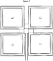
- the electrochemical device can then be assembled into panels by embedding one or more in a mosaic structure as shown in Figure 3 , within a composite.
- the composite comprises a thin glass fiber (or other suitable material) / epoxy (or other suitable material) layer on each side.
- the composite adhesively bonds to the outer current collector metal surfaces of the electrochemical device and provides protection to the outer current collectors.
- the cells can easily be arranged and wired in series connections to provide conventional voltages of 14V, 28V, or even higher voltages within a single panel.
- the mosaic structure offers further benefits of creating a honeycomb like continuous phase.
- the size of the electrochemical devices can be adjusted to optimize different objectives. Very large electrochemical devices can be used to maximize specific energy, or a mosaic of smaller cells can be used to provide redundancy in case an electrochemical device is damaged (by enemy fire or other events).
- the panel is planar, or has a simple (single directional) curve. It can be thin or ultrathin which provides a much higher specific energy for the form factor. This structural integrity is a necessary element of producing a curved cell that will retain its shape. Using the outside current collector layer metals as the packaging of the cell eliminates the non-contributing weight of the pouch packaging.
- the panel material becomes the battery package, which bonds to the metal surfaces of the foils during processing and protects the cells from physical damage.
- the panel material is a composite selected from carbon fiber and fiberglass.
- the majority of the outer surface of the electrochemical device is encased in the polymer. In some embodiments, the electrochemical device and panel are curved.
- the individual electrochemical devices may be laid up as a two-dimensional tiled array within the composite.
- the gaps between the single electrochemical devices of a multi-cell battery will also allow for adhesive bonding between successive layers of composite materials, or will allow the polymeric panel material to fill the gaps.
- the design can employ large numbers of individual electrochemical devices in parallel and in series to provide higher total capacity as well as higher voltages. Further the multi-electrochemical device two-dimensional array design provides a high level of redundancy where if one electrochemical device is damaged, the remainder of the electrochemical devices will still function.
- the layers in the electrochemical device are fully bonded rather than a stack of loose individual layers.
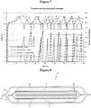
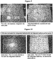
- Outer packaging is not needed for the electrochemical device; instead the current collectors serve as part or all of the packaging, as shown in the cell design of Figure 4 and the image of Figure 5 .
- the electrochemical device as it is a laminated structure, can be easily fabricated in a simple curved structure as well a flat panel.
- the device must have the appropriate dimensions for the curvature and must be fabricated in or near the final shape. Complex contours are possible by pre-forming the foils.
- the outer current collector forms one terminal, which may be either copper or aluminum foil, may have a tab for the opposite electrode coming though the sealed outer current collectors, or the perimeter seal on one side.
- the device can be structured with copper foil on one side and aluminum (positive terminal) on the other.
- the cells can then be assembled into panels by embedding them in a composite or polymer with a thin composite or resin layer on each side as shown in Figures 3 and 4 .
- the electrochemical device may be incorporated into a variety of fabrication methods, such as hand layup, resin transfer molding, vacuum assisted resin transfer molding, resin film infusion, filament winding, pultrusion, etc., thereby creating complex 3D multifunctional structures (including sandwich constructions, which combine a lightweight core material with laminated composite skins). Adhesion of the electrochemical device within the panel prevents it from behaving as a defect or a void by allowing the matrix to bond to the metal foils.
- the outer current collectors are treated before cell assembly to enhance the adhesion between the resin and the current collector. Methods to enhance adhesion include mechanically or chemically roughening the outer surface of the current collectors to increase surface area, or applying a tie coating such as a silane to the outer surface of the current collector.
- This composite integrates structural and energy functionality into a single component to eliminate the redundancies of parasitic mass that previously existed in the sum of the individual components.
- the result is a multifunctional composite panel that produces a 39% or greater increase in specific energy compared to standard batteries containing the same chemistry, and offers an opportunity to increase payload, operational lifetime, safety, or function compared to state-of-the art battery technologies.
- the electrochemical device is a Li-ion bi-cell that comprises a bonded microporous polymeric separator, copper foil current collectors (about 10 microns thick), aluminum foil current collectors (about 15 microns thick), and liquid EC/EMC electrolyte.
- the electrochemical device has two outside anodes and a double-sided cathode.
- Such an electrochemical device may be 0.33 mm thick, have a nominal open circuit voltage of 3.7 V per cell, and a 5.6 mAh/cm 2 cathode capacity (2.8mAh/cm 2 per side). Assuming a 100 cm 2 cell active area, this equates to a 560 mAh cell capacity producing 2.072 Wh at a mass of 11 g.
- the specific energy is 188.72 Wh/kg
- the areal energy density is 207.2 Wh/m 2 .
- the result would be total energy storage of 2,072 Wh for a vehicle.
- the gain in specific energy for this size device is significant.
- a conventional cell and packaging of this scale weights approximately 4 g more, which means the specific energy would drop to approximately 136 Wh/kg.
- the electrochemical device has an approximately 39% improvement in specific energy over a state-of-the-art Li-ion cell, assuming one could be procured at 0.33 mm thickness.
- the electrochemical devices may be fabricated into a composite at either 95°C or 130°C.
- An upper limit of 130°C allows this technology to be embedded into ultra high molecular weight polyethylene (UHMWPE), such as Dyneema® and Spectra Shield®, or fiberglass composites, such as HJ1, during consolidation.
- UHMWPE ultra high molecular weight polyethylene
- the Freya Energy safety separator (developed by Freya Energy Inc, Melbourne FL, www.freyaenergy.com to provide improved safety in lithium ion cells), was modified by Freya Energy by increasing the percentage bonding resin and changing the thermal protection resin to increase the adhesive bond strength and increase the temperature tolerance for the composite fabrication. Processing pressures are not an issue for the cells as they are designed to withstand 68947 kPa (10,000 psi) hydrostatic pressure; therefore, they should withstand typical composite processing pressures.
- an electrochemical device has multiple electrodes, which together to give a thicker, higher capacity, and higher specific energy device. This is especially useful where the bending modulus is more important than strength (such as in an airfoil) as the thicker device adds thickness to the composite panel.
- a thicker device also facilitates the use of non-woven current collectors in the inner electrodes further increasing specific energy and energy density.
- the electrochemical device is a supercapacitor, or a battery hybridized with a supercapacitor.
- a supercapacitor device that has an anode and cathode material with overall density of about 2g/cm 3
- the electrolyte has a density of about 1g/cm 3
- the anode and cathode material will have a capacitance of about 200F/g
- the capacitance of the system is about 0.2F (because the electrodes are in series).
- a vehicle has usable surface area of 10 m 2 , then there can be a total energy storage of 6.25 Wh due to the supercapacitor alone, for a single layer device with a thickness 70 microns. If multiple layers are formed, the areal energy density will increase. With 20 layers (approaching 1mm thick), the energy density would be 12.5 Wh/m 2 .
- Table 1 shows a breakdown of the attributes of an electrochemical battery and supercapacitor.
- composite materials can offer a multitude of other properties such as good vibrational damping and low coefficient of thermal expansion. These characteristics may be modified to allow them to be engineered for specialized applications.
- the electrochemical device may exploit the structural properties of the composite material that are derived primarily from continuous, oriented high-strength fiber reinforcement in a binding matrix to provide packaging while promoting processability and enhancing properties such as stiffness, and chemical and hygroscopic resistance.
- Laminates may be designed to be isotropic or anisotropic, balanced or unbalanced, symmetric or asymmetric, depending on the in-use forces a component must withstand.
- the electrochemical device may be incorporated into laminates making it possible to develop lightweight, complex shapes and to produce large parts with integral reinforcing members while providing additional functionality afforded by this invention.
- Ingredients for composite materials that may be used with the electrochemical device include, but are not limited to: additives and modifiers, such as, ablatives, colorants, pigments, conductive fillers, coupling agents, decorative flakes, flame/smoke-suppressant additives, foaming agents, low-profile additives, styrene-suppressant additives, thickening agents, toughening agents, UV stabilizers, and viscosity control agents.
- Adhesives include, but are not limited to: acrylic, bismaleimide, cyanoacrylate, epoxy, nylon, phenolic, polyimide, silicone, and urethane.
- Casting resins include, but are not limited to: acrylic, epoxy, and unsaturated polyester.
- Catalysts, promoters, and curing agents include, but are not limited to: cobalt naphthenate, amines, hardeners, initiators, and peroxides.
- Coatings and sizings include, but are not limited to: conductive, decorative, electrostatic, EMI-attenuation, flame retardant, in-mold, paint, powder, and protective.
- Compounds that may be used include, but are not limited to: bulk molding (BMC), fairing compounds (formerly paste systems), low-pressure molding, sheet molding (SMC), solid surface, thermoplastic, and thick molding.
- Core materials and flow media include, but are not limited to: balsa, flow media for resin infusion, foam core, honeycomb, inorganic, expanding syntactic core, and nonexpanding syntactic core.
- Fabrics that may be used include, but are not limited to: aramid, aramid/glass hybrid, C-glass, carbon, carbon/aramid hybrid, carbon/glass hybrid, ceramic, E-Glass, metallized, and structural high-strength glass (S- and R-type).
- Inorganic fibers that may be used include, but are not limited to: aluminum, basalt, boron, C-Glass, ceramic, E-Glass, quartz, silicon carbide, and structural high-strength glass (S- and R-type).
- Organic fibers that may be used include, but are not limited to: aramid, PAN-based carbon, pitch-based carbon, rayon-based carbon, hybrid commingled fibers, nylon, polybenzimidazole, polyester, polyethylene, and UHMW polyethylene (ultra-high molecular weight).
- Fillers that may be used include, but are not limited to: alumina trihydrate, calcium carbonate, calcium sulfate, carbon black, gypsum, kaolin, mica, microspheres, milled glass fiber, nanophase (organic/inorganic), recyclate, silica, amorphous silica, talc, and wollastonite.
- Gel coats that may be used include, but are not limited to: anti-fouling, chemical-/corrosion-resistant, conductive, fire-retardant, general-purpose, marine, potable-water grades, and UV-curable.
- Matrix materials that may be used include, but are not limited to: ceramic and metallic.
- Thermoplastic matrix resins that may be used include, but are not limited to: acetal, acrylonitrile butadiene styrene (ABS), liquid crystal polymer, methyl methacrylate, nylon (polyamide), PBT, polyamide-imide, polyarylene ketone, sulfide, polycarbonate, polyester (PET), polyether ketone family (PEK, PEKK, PEEK), polyetherimide, polyethersulfone, polyethylene, polyimide, polyphenylene sulfide (PPS), polypropylene, polyvinyl chloride, fluorinated polymers, polystyrene, styrene monomer (diluent), acrylonitrile, polybutylene terephthalate, polyphenylene oxide, polysulfone, polydimethylsiloxane, polyurethane, polyvinyl alcohol, PVDF, and polytetrafluoroethylene.
- ABS acrylonitrile butad
- Thermoset matrix resins that may be used include, but are not limited to: acrylic, bismaleimide, cyanate ester, epoxy, phenolic, polyimide, unsaturated polyester, urethane, UV-curable, and vinyl ester.
- Unimpregnated preforms that may be used include, but are not limited to: aramid, carbon, ceramic, chopped fiber, continuous fiber, E-Glass, hybrid fiber, quartz, and structural high-strength glass (S- and R-type).
- Thermoplastic prepregs that may be used include, but are not limited to: commingled/cowoven yarns, fabric, interlaced, mat, RTP sheet (GMT), tape, and tow or roving.
- Thermoset prepregs that may be used include, but are not limited to: bismaleimide, cyanate ester, epoxy, phenolic, unsaturated polyester, polyimide, and vinyl ester.
- Unimpregnated reinforcements that may be used include, but are not limited to: aramid, aramid/glass hybrid, C-glass, carbon, carbon/aramid hybrid, carbon/glass hybrid, ceramic, E-Glass, and structural high-strength glass (S- and R-type).
- the electrochemical device is incorporated into neat thermoset or thermoplastic polymers without additional reinforcement using traditional thermoset or thermoplastic processing techniques, such as blow molding, injection molding, extrusion, thermoforming, vacuum forming, compression molding, etc.
- the electrochemical device and panel composite integrates ballistic protection and energy functionality into a single component to reduce the mass that previously existed in the sum of the individual components.
- the result is a multifunctional armor panel, as shown in Figure 6 , that produces higher specific energy and offers an opportunity to increase payload compared to conventional battery technologies.
- the cell may be embedded within existing personal protective equipment suits.
- a Nomex-based composite suit (coupled with an adhesive) will provide a suitable package for the battery; thus, providing battery and structural functionality.
- the electrochemical device and panel composite may replace inert structural components and/or aerodynamic/hydrodynamic surfaces on Unmanned Air Vehicles (UAV), Unmanned Underwater Vehicles (UUV), and missile bodies while providing electrical power to the vehicle. Increasing the energy density can expand their range/payload capability.
- UAV Unmanned Air Vehicles
- UUV Unmanned Underwater Vehicles
- missile bodies while providing electrical power to the vehicle. Increasing the energy density can expand their range/payload capability.
- the electrochemical device and panel composite may be useful for other applications such as: aerospace applications, such as for fuselage, wings, wingbox, tail, empennage, ailerons, spoilers, composite inboard and outboard landing flaps, landing gear, rear spars, and fixed trailing edge assemblies, and interiors, such as seating, doors, floors, walls, aesthetic components, horizontal stabilizer, elevator and rudder, winglets, wing fixed trailing edge, wing-to-fuselage fairing, engine cowlings, engine pylons, pressure bulkhead, launch vehicles, fuel tanks, exploration instruments, satellites, space bases, and UAV airframes.
- Automotive applications include, but are not limited to: body panels, structural components, under-the-hood parts, frames/chassis, and drive shafts.
- Boating applications include, but are not limited to: yacht rigging systems (masts, shrouds, stays, and spreaders), hull, deck, and interior structure.
- Civil infrastructure applications include, but are not limited to: bridges and bridge beams, decking, and enclosures.
- Building construction applications include, but are not limited to: countertops, doors, window frames, bathtubs, and other home construction/remodeling materials, structural frame, cladding, roofing, siding, decking, emergency housing, truck trailers, outdoor signage, earthquake repair and upgrades/column wrap, manhole covers, trench covers, acoustic wall panels, marine piling, piers, residential wall panels, tanks, grating, platforms, and walkways.
- Appliances and business equipment applications include, but are not limited to: handles, housing, and components.
- Fuel cells applications include, but are not limited to: system components, such as bipolar plates, end plates, fuel tanks, and other system components.
- Oil and gas applications include, but are not limited to: composite risers, deep-sea umbilical, and piping.
- Sports and recreation applications include, but are not limited to: skis, fishing rods, tennis rackets, kayaks and paddles, windsurfing masts and boards, hockey sticks, bicycle components, and golf clubs and shafts.
- Renewable energy applications include, but are not limited to: wind turbine blades, wave and tidal generator rotor blades.
- Utility infrastructure applications include, but are not limited to: transmission towers, distribution poles and cross arms, battery boxes, casings, and telescoping portable antennas.
- Example 1 Fabrication of a structural battery
- a structural battery design consists of a Li-ion bi-cell that incorporates:
- the outside anodes were cut from commercial stock, and the perimeter was cleaned using NMP to form the area for the perimeter seal.
- two picture frame seals (with one extended side) were cut from 3 mil Suryln® film.
- the picture frames were then heat sealed to the anodes.
- Two pieces of Freya Energy safety separator modified by the manufacturer to improve adhesion and provide higher temperature tolerance were cut about 10 mm larger than the cathode.
- a double sided commercial cathode was cut to shape with a terminal so it extends beyond the perimeter of the anode.
- the cathode terminal was then coated with a high temperature polymer solution (PEI) and dried followed by an adhesion promoting layer of ethylene acrylic acid (EAA) and dried.
- PEI high temperature polymer solution
- EAA ethylene acrylic acid
- the separator layers were then laminated to each side of the cathode.
- the separator became bonded to cathode and to, each other beyond the perimeter of the electrode.
- the excess separator was trimmed off leaving 1 to 3 mm around the perimeter of the cathode to insure complete encapuslation to prevent shorting.
- the cell was then assembled by stacking the 3 layers together in careful alignment and heat sealing the three sides of the picture frame, leaving the fourth side with the extended Surlyn film open.
- the cell was then activated by adding electrolyte through the open side.
- the cell was ready to incorporate into a composite.
- the battery has a high specific energy and it is fully bonded rather than a stack of loose individual layers.
- the reason for this is that the cell is designed to be laminatable (with a suitable perimeter seal and laminatable separator). Outer packaging is not used; instead the foil current collectors serve as part or all of the outside packaging as shown in the cell design of Figure 4 and the image of Figure 5 .
- the cell is very thin with thin foil current collectors (10-25 micron) that act as air and moisture barriers.
- the bi-cell with two outside anodes and a double-sided cathode in between, which, doubles the capacity and increases the specific energy slightly.
- the battery functionality and improved adhesion in the panels thereby creating a structural battery component that can be integrated into composite panels.
- This battery can be integrated into a fiber-reinforced composite where the layers of the composite will provide both structure and battery packaging (including electrical isolation). Examples of reinforcements include carbon fiber and fiberglass.
- the battery is 0.33 mm thick, has a nominal open circuit voltage of 3.7 V per cell, and has a 5.6 mAh/cm 2 cathode capacity. Assuming a 100 cm 2 cell active area, this equates to a 560 mAh cell capacity producing 2.072 Wh at a mass of 11 g. Therefore, the specific energy is 188.72 Wh/kg, and the areal energy density is 207.2 Wh/m 2 .
- the gain in specific energy with this approach is significant. For example, a conventional battery of this scale weights approximately 4 g more, which means the specific energy would drop to approximately 136 Wh/kg.
- the electrochemical device has an approximately 39% improvement in specific energy over a state-of-the-art Li-ion cell, assuming one could be procured at 0.33 mm thickness.
- a structural battery design as shown in Figure 8 , consists of a Li-ion bi-cell electrochemical device (10) that incorporates:
- the outside current collector was cut to size.
- the current collector may be two pieces or one piece folded.
- the cathode slurry was then patch coated by applying masking tape to the perimeter of the current collector and drawing down the slurry over the masked foil.
- the cathodes were then dried.
- Two pieces of special Freya Energy safety separator with improved adhesion and higher temperature tolerance were cut to size (about 10 mm larger than the anode).
- a double sided anode or hand coated double sided anode was cut to shape.
- a small soft copper tube was used for the terminal which extends beyond the perimeter of the cathode.
- the anode terminal was then coated with a high temperature polymer solution (PEI or PAI) and dried.
- PEI or PAI high temperature polymer solution
- Tin adhesion promoting layer of acidified polypropylene was heat sealed to the tab.
- the separator layers were then placed on each side of the anode and heat sealed around the perimeter. The excess separator was trimmed off beyond the heat seal leaving the seal around the perimeter of the anode insuring complete encapsulation to prevent shorting.
- the cell was then assembled by stacking the 3 layers together in careful alignment. Two sides were ultrasonically welded. The third side with the anode tab was then ultrasonically welded with a formed horn that bridges the anode terminal which was bonded to the aluminum outer current collector by heat. The fourth side was left open for activation. The electrolyte was added through the open side and then the side was ultrasonically welded. The cell was subjected to formation to charge the cell.
- Example 3 Fabrication of a curved battery
- a curved structural battery design consists of a Li-ion bi-cell that incorporates:
- the outside current collector was cut to size.
- the current collector may be two pieces or one piece folded. If the current collected is folded, the folded edge cannot be along the curve edge.
- the cathode slurry was then patch coated using a patterned screen (like silk screening) and drawing down the slurry over the screen. The cathodes were then dried and calendared. Two pieces of special Freya Energy safety separator with improved adhesion and higher temperature tolerance were cut to size (about 10 mm larger than the anode).
- a double sided anode was made by cutting a copper coated non-woven current collector to size and attaching a small soft copper tube for the terminal using a conductive adhesive.
- the non-woven current collector was then dip coated in the anode slurry coating to saturate the non-woven and give the desired weight.
- the anode was then dried and calendered.
- the anode terminal was coated with a high temperature polymer solution (PEI or PAI) and dried, followed by heat sealing an adhesion promoting layer of acidified polypropylene to the tab.
- the separator layers were then placed on each side of the anode and heat sealed around the perimeter. The excess separator was trimmed off beyond the heat seal leaving the seal around the perimeter of the anode insuring complete encapsulation to prevent shorting.
- the cell was then assembled by stacking the 3 layers together in careful alignment.
- the cell does not comprise a folded cathode
- one of the straight sides is ultrasonically welded.
- the assembly was then formed over a round or contoured anvil and the two curved sides are welded - either stepwise with a static unit continuously using an ultrasonic seamer.
- the side with the anode tab is treated as described in Example 1.
- the fourth side was left open for activation.
- the electrolyte was added through the open side and then the side is ultrasonically welded.
- the cell was subjected to formation to charge the cell.
- the cell now had a permanent curvature to it and was ready to incorporate into a curved composite (such as the housing of a missile or torpedo).
- a urethane mixture prepolymer, polyols, and catalyst components was metered as a liquid from a casting machine on top of the armor plate.
- Ballistic testing was conducted in accordance with the provisions of MIL-STD-662F, dated 18 December 1997, using caliber .30-06 Springfield, 166 grain, AP, M2 ammunition.
- the test samples were mounted on an indoor range, 25.0 feet from the muzzle of a test barrel to produce zero degree obliquity impacts.
- Velocity screens were positioned at 10.0 and 20.0 feet, that in conjunction with elapsed time counters (chronographs), were used to compute projectile velocities 15.0 feet from the muzzle.
- Penetrations were determined by visual examination of a 0.020 inch thick aluminum alloy 2024T3 witness panel positioned 6.0 inches behind, and parallel to, the test samples.
Landscapes
- Chemical & Material Sciences (AREA)
- Chemical Kinetics & Catalysis (AREA)
- Electrochemistry (AREA)
- General Chemical & Material Sciences (AREA)
- Engineering & Computer Science (AREA)
- Power Engineering (AREA)
- Microelectronics & Electronic Packaging (AREA)
- Manufacturing & Machinery (AREA)
- Inorganic Chemistry (AREA)
- Materials Engineering (AREA)
- Secondary Cells (AREA)
- Sealing Battery Cases Or Jackets (AREA)
- Cell Separators (AREA)
- Cell Electrode Carriers And Collectors (AREA)
- Battery Mounting, Suspending (AREA)
- Connection Of Batteries Or Terminals (AREA)
- Battery Electrode And Active Subsutance (AREA)
- Fuel Cell (AREA)
- Electric Double-Layer Capacitors Or The Like (AREA)
Claims (15)
- Dispositif électrochimique comprenant une ou plusieurs anodes, cathodes, et séparateurs ; et deux collecteurs de courant ou plus ;
dans lequel l'anode et la cathode se trouvent entre les deux collecteurs de courant et adhèrent chacune à un collecteur de courant adjacent, et le séparateur se trouve entre l'anode et la cathode et est adhérant à l'anode et à la cathode ;
dans lequel les collecteurs de courant sont une barrière contre l'humidité et/ou l'oxygène ; et
caractérisé en ce que
les collecteurs de courant sont collés ensemble pour créer un conteneur étanche pour l'anode, la cathode, et le séparateur ; de préférence dans lequel les anodes ou les cathodes extérieures sont les collecteurs de courant. - Dispositif électrochimique selon la revendication 1, dans lequel le dispositif est hermétiquement scellé à l'intérieur des collecteurs de courant.
- Dispositif électrochimique selon l'une des revendications 1 ou 2, comprenant de plus un joint de périmètre, dans lequel le joint de périmètre est collé entre les deux collecteurs de courant.
- Dispositif électrochimique selon l'une des revendications précédentes, dans lequel le dispositif selon l'invention comprend deux anodes ou plus, deux cathodes ou plus, ou les deux.
- Dispositif électrochimique selon l'une des revendications précédentes, dans lequel au moins une électrode a une double face ; de préférence dans lequel l'électrode à double face est enroulée dans un séparateur qui est hermétiquement scellé autour de l'électrode.
- Dispositif électrochimique selon l'une des revendications précédentes, dans lequel toutes les cathodes sont connectées électriquement et toutes les anodes sont connectées électriquement.
- Dispositif électrochimique selon l'une des revendications précédentes, dans lequel le joint de périmètre est sélectionné parmi les éléments suivants : une résine ionomérique, un acide acrylique d'éthylène (EAA), une polyoléfine, une polyoléfine acidifiée, un diflorure de polyvinylidène (PVDF), un polyimide, un polyamide, un époxy, et un polyuréthane.
- Dispositif électrochimique selon l'une des revendications précédentes, dans lequel le séparateur est sélectionné parmi les éléments suivants : une polyoléfine microporeuse, un polyéthylène téréphtalate (PET) revêtu de céramique, et un séparateur PVDF ; le séparateur étant revêtu d'une couche adhésive sélectionnée parmi : un copolymère de poly(vinylidène fluorure-co-hexafluoropropylène) (PVDF-HFP), un polypropylène chloré, et un polypropylène/anhydride maléique ; de préférence dans lequel le séparateur est un polymère sélectionné parmi des polyimides et des polyamides, dans lequel le polymère est interdispersé avec au moins un adhésif ; de façon plus préférentielle dans lequel le séparateur est un polymère sélectionné parmi un PVDF réticulé et un oxyde de polyéthylène (PEO) réticulé.
- Dispositif électrochimique selon l'une des revendications précédentes, dans lequel le séparateur a une épaisseur de 10 µm (= 10 microns) à 50 µm (= 50 microns).
- Dispositif électrochimique selon l'une des revendications précédentes, dans lequel la taille des pores dans le séparateur va de 30 nm à 10 µm (= 10 microns).
- Panneau structurel comprenant le dispositif électrochimique selon l'une des revendications précédentes ; de préférence dans lequel le panneau comprend un polymère, et les collecteurs de courant externes du dispositif électrochimique sont collés au polymère.
- Panneau structurel selon la revendication 11, dans lequel le panneau comprend une composition de résine et un renfort.
- Panneau structurel selon l'une quelconque des revendications 11 à 12, dans lequel une majorité de la surface extérieure du dispositif électrochimique est enchâssée dans le polymère.
- Panneau structurel selon l'une quelconque des revendications 11 à 13, dans lequel le dispositif électrochimique et le panneau épousent un contour de surface.
- Procédé de fabrication d'un dispositif électrochimique selon la revendication 1, comprenant les étapes consistant à :fournir un ou plusieurs électrolytes, et un ou plusieurs séparateurs ; et deux collecteurs de courant ou plus et deux électrodes ou plus ; dans lequel au moins une électrode est une anode et une électrode est une cathode ;le dispositif est assemblé en empilant un collecteur de courant, une anode, un séparateur, une cathode, et un deuxième collecteur de courant ;l'électrolyte est ajouté au séparateur ; etla pile est stratifiée en la chauffant à 90 °C ou plus sous au moins 103 kPa (=15 psi) de pression.
Applications Claiming Priority (2)
| Application Number | Priority Date | Filing Date | Title |
|---|---|---|---|
| US201261643947P | 2012-05-08 | 2012-05-08 | |
| PCT/US2013/040149 WO2014021970A2 (fr) | 2012-05-08 | 2013-05-08 | Cellule multifonction pour applications structurales |
Publications (2)
| Publication Number | Publication Date |
|---|---|
| EP2852990A2 EP2852990A2 (fr) | 2015-04-01 |
| EP2852990B1 true EP2852990B1 (fr) | 2018-01-31 |
Family
ID=49667546
Family Applications (1)
| Application Number | Title | Priority Date | Filing Date |
|---|---|---|---|
| EP13795889.8A Not-in-force EP2852990B1 (fr) | 2012-05-08 | 2013-05-08 | Cellule multifonction pour applications structurales |
Country Status (5)
| Country | Link |
|---|---|
| US (1) | US9520580B2 (fr) |
| EP (1) | EP2852990B1 (fr) |
| JP (1) | JP6220865B2 (fr) |
| KR (1) | KR101984203B1 (fr) |
| WO (1) | WO2014021970A2 (fr) |
Cited By (7)
| Publication number | Priority date | Publication date | Assignee | Title |
|---|---|---|---|---|
| WO2020102661A1 (fr) * | 2018-11-15 | 2020-05-22 | ZAF Energy Systems, Incorporated | Cellule de poche alcaline avec bornes revêtues |
| DE102020129659A1 (de) | 2020-11-11 | 2022-05-12 | Airbus Operations Gmbh | Integriertes Aktorelement mit elektroaktivem Polymer |
| DE102021100713A1 (de) | 2021-01-15 | 2022-07-21 | Airbus Operations Gmbh | Strukturbauteil für ein Fahrzeug |
| DE102021101976A1 (de) | 2021-01-28 | 2022-07-28 | Airbus Operations Gmbh | Strukturbauteil für ein Fahrzeug |
| EP4040635A1 (fr) | 2021-02-08 | 2022-08-10 | Airbus Operations GmbH | Composant structural pour un véhicule et agencement de fixation |
| DE102021104928A1 (de) | 2021-03-02 | 2022-09-08 | Airbus Operations Gmbh | Passagier-Serviceeinheit für eine Passagierkabine eines Luft- oder Raumfahrzeugs |
| EP4216337A1 (fr) | 2022-01-20 | 2023-07-26 | Airbus Operations GmbH | Batterie structurale pour véhicule |
Families Citing this family (50)
| Publication number | Priority date | Publication date | Assignee | Title |
|---|---|---|---|---|
| GB2505166B (en) * | 2012-08-03 | 2018-04-04 | Bae Systems Plc | Component including a structural supercapacitor |
| US10121607B2 (en) * | 2013-08-22 | 2018-11-06 | Corning Incorporated | Ceramic separator for ultracapacitors |
| CN105637705B (zh) * | 2013-10-16 | 2019-04-19 | Agc株式会社 | 供电结构、窗用树脂制板状体及其制造方法 |
| US9660470B2 (en) | 2014-09-08 | 2017-05-23 | Nokia Technologies Oy | Flexible, hybrid energy generating and storage power cell |
| DE102014113588A1 (de) * | 2014-09-19 | 2016-03-24 | Manz Ag | Verfahren zur Herstellung einer Batteriezelle |
| CA2971603A1 (fr) * | 2014-12-24 | 2016-06-30 | 3M Innovative Properties Company | Reseaux adhesifs poreux dans des dispositifs electrochimiques |
| GB2537935B (en) | 2015-05-01 | 2021-02-24 | Intelligent Energy Ltd | Aerial vehicle |
| US10229329B2 (en) | 2016-11-08 | 2019-03-12 | Dedrone Holdings, Inc. | Systems, methods, apparatuses, and devices for identifying, tracking, and managing unmanned aerial vehicles |
| US12494064B2 (en) | 2015-09-23 | 2025-12-09 | Dedrone Holdings, Inc. | Identifying, tracking, and disrupting unmanned aerial vehicles |
| US12027660B2 (en) * | 2015-11-02 | 2024-07-02 | Rutgers, The State University Of New Jersey | Electrochemical cell having thin metal foil packaging and a method for making same |
| US10414358B2 (en) | 2016-02-03 | 2019-09-17 | The Boeing Company | Composite panel power system |
| CN113644380B (zh) * | 2016-03-03 | 2023-07-28 | 苹果公司 | 用于湿法层合和干法层合电池单元的粘结剂 |
| US11289769B2 (en) | 2016-03-03 | 2022-03-29 | Apple Inc. | Binders for wet and dry lamination of battery cells |
| WO2017152836A1 (fr) | 2016-03-08 | 2017-09-14 | 北京好风光储能技术有限公司 | Cellule pour batterie à pâte au lithium, et module de batterie à pâte au lithium |
| CN107681115B (zh) * | 2016-08-01 | 2020-08-04 | 北京好风光储能技术有限公司 | 一种锂浆料电池的负极片 |
| CN107681114B (zh) * | 2016-08-01 | 2020-08-14 | 北京好风光储能技术有限公司 | 一种正极片及制备工艺、以及含有该正极片的锂浆料电池 |
| EP3222514B1 (fr) * | 2016-03-21 | 2019-05-22 | Airbus Operations GmbH | Panneau de revêtement avec une couche de stockage d'énergie pour un avion ou un engin spatial et procédé de fabrication associé |
| US10147557B2 (en) | 2016-09-13 | 2018-12-04 | The Mitre Corporation | Enhanced structural supercapacitors |
| US10522874B2 (en) * | 2016-11-01 | 2019-12-31 | The Boeing Company | Solid state fiber-based battery system and method of forming same |
| EP3336948B1 (fr) | 2016-12-14 | 2019-09-11 | Airbus Operations GmbH | Procédé permettant de personnaliser et intégrer une unité de pile à combustible dans un véhicule |
| US11233276B2 (en) | 2017-04-07 | 2022-01-25 | Beijing Hawaga Power Storage Technology Company Ltd. | Lithium slurry battery system |
| TWI887813B (zh) * | 2017-04-18 | 2025-06-21 | 英商立可行有限公司 | 能量儲存裝置 |
| WO2019055893A1 (fr) * | 2017-09-18 | 2019-03-21 | Avx Corporation | Ultracondensateur à faible courant de fuite |
| US10934013B2 (en) * | 2017-09-22 | 2021-03-02 | The Boeing Company | Aircraft fuselage apparatus having embedded structural batteries |
| TWI676315B (zh) | 2017-10-20 | 2019-11-01 | 輝能科技股份有限公司 | 複合式電池芯 |
| CN108461285B (zh) * | 2017-12-29 | 2023-07-11 | 安徽瀚宇电气有限公司 | 一种缓冲式防鼓肚自愈式机车电容器 |
| US10991935B2 (en) | 2018-03-27 | 2021-04-27 | The Mitre Corporation | Structural lithium-ion batteries with carbon fiber electrodes |
| WO2020099351A1 (fr) * | 2018-11-12 | 2020-05-22 | Fischer Eco Solutions Gmbh | Procédé de collage de deux plaques entre elles pour une pile à combustible, en particulier de collage de plaques bipolaires dans une pile à combustible |
| DE102019218979A1 (de) | 2019-12-05 | 2021-06-10 | Airbus Operations Gmbh | Leichtbaustruktur für ein Fahrzeug und Luftfahrzeug |
| KR102916834B1 (ko) * | 2019-12-13 | 2026-01-22 | 현대자동차주식회사 | 충방전 기능을 갖는 차체 부재 |
| DE102019219594A1 (de) * | 2019-12-13 | 2021-06-17 | Elringklinger Ag | Flächenmaterial, Sandwichmaterial, elektrochemische Speichereinheit und Verfahren zur Herstellung eines Flächenmaterials |
| KR102939187B1 (ko) * | 2020-02-27 | 2026-03-13 | 현대자동차주식회사 | 충방전 기능을 갖는 차체 부재 |
| US12325073B2 (en) * | 2020-03-18 | 2025-06-10 | Battelle Savannah River Alliance, Llc | Structural vehicle components for hydrogen storage |
| CN111504141A (zh) * | 2020-03-31 | 2020-08-07 | 江苏厚生新能源科技有限公司 | 一种高能量密度锂离子电池在鱼雷中的应用 |
| WO2021211428A1 (fr) | 2020-04-14 | 2021-10-21 | Saint-Gobain Performance Plastics Corporation | Film composite |
| KR102447927B1 (ko) * | 2020-08-20 | 2022-09-28 | 한국과학기술원 | 고성능 복합재료 구조 전지 |
| DE102020133854A1 (de) | 2020-12-16 | 2022-06-23 | Airbus Operations Gmbh | Tragende Verbundschichtstoffstruktur für ein Luftfahrzeugbauteil, damit hergestelltes Luftfahrzeugbauteil und Luftfahrzeug |
| CN116325276B (zh) * | 2021-05-24 | 2026-02-27 | 株式会社Lg新能源 | 单元电芯及包括该单元电芯的电池电芯 |
| CN116325335B (zh) | 2021-05-24 | 2026-02-27 | 株式会社Lg新能源 | 单元电芯及包括该单元电芯的电池电芯 |
| US11984611B2 (en) * | 2021-08-17 | 2024-05-14 | Beta Air, Llc | Stack battery pack for electric vertical take-off and landing aircraft |
| US11705601B2 (en) | 2021-08-18 | 2023-07-18 | Lockheed Martin Corporation | Structural battery for an aircraft vehicle |
| CN113782838B (zh) * | 2021-11-11 | 2022-03-15 | 深圳市兴禾自动化股份有限公司 | 一种电芯热复合制成工艺 |
| CN113782820B (zh) * | 2021-11-11 | 2022-03-15 | 深圳市兴禾自动化股份有限公司 | 一种极片与极片袋叠合电芯 |
| CN113782839B (zh) * | 2021-11-11 | 2022-03-25 | 深圳市兴禾自动化股份有限公司 | 一种在线式极片制袋叠合工艺及其制袋叠合生产线 |
| JP7808250B2 (ja) * | 2022-01-27 | 2026-01-29 | 株式会社発明屋 | 骨格部材型電池装置、構造体、移動体、構造体の製造方法及び電池指向の構造設計方法 |
| US12278384B2 (en) * | 2022-04-06 | 2025-04-15 | Meta Platforms Technologies, Llc | High capacity curved battery cells |
| US12555777B2 (en) | 2022-09-09 | 2026-02-17 | Apple Inc. | Layered structure of battery electrodes |
| DE102023206462A1 (de) * | 2023-07-07 | 2025-01-09 | Benecke-Kaliko Aktiengesellschaft | Mehrschichtige Verbundstruktur |
| CN116864864B (zh) * | 2023-08-23 | 2024-06-04 | 深圳市海芯电池有限公司 | 一种用于锂电池组的节能加热装置及加热方法 |
| KR20260021936A (ko) * | 2024-08-07 | 2026-02-19 | 주식회사 엘지에너지솔루션 | 이차 전지의 제조 방법 |
Family Cites Families (29)
| Publication number | Priority date | Publication date | Assignee | Title |
|---|---|---|---|---|
| JPS5940470A (ja) * | 1982-08-30 | 1984-03-06 | Fuji Elelctrochem Co Ltd | 積層電池 |
| JPS5972374A (ja) * | 1982-10-20 | 1984-04-24 | 国産金属工業株式会社 | 錠装置 |
| JPS60184265U (ja) * | 1984-05-17 | 1985-12-06 | カシオ計算機株式会社 | 薄型電池 |
| JPH01239759A (ja) * | 1988-03-18 | 1989-09-25 | Hitachi Maxell Ltd | 薄形リチウム電池 |
| JPH01239761A (ja) * | 1988-03-18 | 1989-09-25 | Hitachi Maxell Ltd | 薄形リチウム電池 |
| JPH02112149A (ja) * | 1988-10-20 | 1990-04-24 | Hitachi Maxell Ltd | 薄形リチウム電池 |
| JP3270175B2 (ja) * | 1992-04-15 | 2002-04-02 | 日本電気株式会社 | 電気二重層コンデンサ |
| JPH08167415A (ja) * | 1994-12-14 | 1996-06-25 | Sanyo Electric Co Ltd | 薄型高分子固体電解質電池及びその製造方法 |
| JP3544106B2 (ja) * | 1997-09-29 | 2004-07-21 | 株式会社ユアサコーポレーション | 薄形非水電解質電池 |
| JP2000048781A (ja) * | 1998-07-28 | 2000-02-18 | Ricoh Co Ltd | 偏平薄型電池 |
| US7211348B2 (en) | 2000-08-10 | 2007-05-01 | University Of Virginia Patent Foundation | Multifunctional battery and method of making the same |
| US6805946B2 (en) | 2000-12-04 | 2004-10-19 | Advanced Ceramics Research, Inc. | Multi-functional composite structures |
| US7063917B2 (en) | 2001-02-21 | 2006-06-20 | Ahlstrom Mount Holly Springs, Llc | Laminated battery separator material |
| JP2003151558A (ja) * | 2001-11-14 | 2003-05-23 | Matsushita Electric Ind Co Ltd | 非水電解質二次電池 |
| DE10219424A1 (de) * | 2002-05-02 | 2003-11-20 | Varta Microbattery Gmbh | Galvanisches Element mit dünnen Elektroden |
| US7318984B2 (en) | 2002-05-17 | 2008-01-15 | Nitto Denko Corporation | Adhesive composition-supporting separator for battery and electrode/separator laminate obtained by using the same |
| US7267908B2 (en) * | 2004-08-30 | 2007-09-11 | Toyota Technical Center Usa, Inc. | In cycling stability of Li-ion battery with molten salt electrolyte |
| JP2006269295A (ja) * | 2005-03-24 | 2006-10-05 | Ngk Spark Plug Co Ltd | 薄型電池およびその製造方法 |
| US20070015021A1 (en) * | 2005-07-18 | 2007-01-18 | Yaron Shrim | Canless bi-cell |
| JP4720384B2 (ja) * | 2005-09-01 | 2011-07-13 | 日産自動車株式会社 | バイポーラ電池 |
| GB0519807D0 (en) | 2005-09-28 | 2005-11-09 | Welding Inst | Fuel cell assembly |
| US7855017B1 (en) | 2005-11-09 | 2010-12-21 | The United States Of America As Represented By The Secretary Of The Army | Structural batteries and components thereof |
| US20080268341A1 (en) * | 2007-03-14 | 2008-10-30 | Teck Cominco Metals Ltd. | High power batteries and electrochemical cells and methods of making same |
| US20090202903A1 (en) * | 2007-05-25 | 2009-08-13 | Massachusetts Institute Of Technology | Batteries and electrodes for use thereof |
| GB0823260D0 (en) | 2008-12-20 | 2009-01-28 | Qinetiq Ltd | Multi-functional composite |
| WO2010087963A1 (fr) * | 2009-01-27 | 2010-08-05 | G4 Synergetics, Inc. | Confinement à volume variable pour dispositifs de stockage d'énergie |
| HUE036950T2 (hu) | 2009-03-09 | 2018-08-28 | Asahi Chemical Ind | Poliolefin mikropórusos membrán, amely villamosenergia-tároló eszköz elválasztóelemeként használható |
| EP2534718B1 (fr) | 2010-02-09 | 2017-08-02 | BAE Systems PLC | Composante comprenant une batterie réchargeable |
| KR101217562B1 (ko) * | 2010-11-16 | 2013-01-02 | 삼성전자주식회사 | 가요성 전지 및 이를 포함하는 가요성 전자기기 |
-
2013
- 2013-05-08 US US14/398,004 patent/US9520580B2/en active Active
- 2013-05-08 EP EP13795889.8A patent/EP2852990B1/fr not_active Not-in-force
- 2013-05-08 JP JP2015511662A patent/JP6220865B2/ja not_active Expired - Fee Related
- 2013-05-08 KR KR1020147034177A patent/KR101984203B1/ko not_active Expired - Fee Related
- 2013-05-08 WO PCT/US2013/040149 patent/WO2014021970A2/fr not_active Ceased
Cited By (8)
| Publication number | Priority date | Publication date | Assignee | Title |
|---|---|---|---|---|
| WO2020102661A1 (fr) * | 2018-11-15 | 2020-05-22 | ZAF Energy Systems, Incorporated | Cellule de poche alcaline avec bornes revêtues |
| DE102020129659A1 (de) | 2020-11-11 | 2022-05-12 | Airbus Operations Gmbh | Integriertes Aktorelement mit elektroaktivem Polymer |
| DE102021100713A1 (de) | 2021-01-15 | 2022-07-21 | Airbus Operations Gmbh | Strukturbauteil für ein Fahrzeug |
| DE102021101976A1 (de) | 2021-01-28 | 2022-07-28 | Airbus Operations Gmbh | Strukturbauteil für ein Fahrzeug |
| EP4040635A1 (fr) | 2021-02-08 | 2022-08-10 | Airbus Operations GmbH | Composant structural pour un véhicule et agencement de fixation |
| DE102021102901A1 (de) | 2021-02-08 | 2022-08-11 | Airbus Operations Gmbh | Strukturbauteil für ein Fahrzeug und Befestigungsanordnung |
| DE102021104928A1 (de) | 2021-03-02 | 2022-09-08 | Airbus Operations Gmbh | Passagier-Serviceeinheit für eine Passagierkabine eines Luft- oder Raumfahrzeugs |
| EP4216337A1 (fr) | 2022-01-20 | 2023-07-26 | Airbus Operations GmbH | Batterie structurale pour véhicule |
Also Published As
| Publication number | Publication date |
|---|---|
| US9520580B2 (en) | 2016-12-13 |
| WO2014021970A3 (fr) | 2014-04-03 |
| JP2015520923A (ja) | 2015-07-23 |
| WO2014021970A2 (fr) | 2014-02-06 |
| US20150093629A1 (en) | 2015-04-02 |
| KR20150013249A (ko) | 2015-02-04 |
| EP2852990A2 (fr) | 2015-04-01 |
| KR101984203B1 (ko) | 2019-05-30 |
| JP6220865B2 (ja) | 2017-10-25 |
Similar Documents
| Publication | Publication Date | Title |
|---|---|---|
| US9520580B2 (en) | Multifunctional cell for structural applications | |
| KR102778543B1 (ko) | 축전 디바이스용 외장재 및 축전 디바이스 | |
| Thomas et al. | Multifunctional structure-battery composites for marine systems | |
| KR101250901B1 (ko) | 시트형상 이차전지 및 그 제조방법 | |
| KR101286827B1 (ko) | 전극 및 그의 제작 방법 | |
| US20130209839A1 (en) | Component including a rechargeable battery | |
| CN107431181B (zh) | 多功能能量存储复合材料 | |
| US20240063364A1 (en) | Structural lithium-ion batteries with carbon fiber electrodes | |
| US20130059173A1 (en) | Component including a rechargeable battery | |
| US20150044572A1 (en) | Electrical energy storage structures | |
| US11322810B2 (en) | Jacketing of structural batteries | |
| EP2765629A1 (fr) | Séparateur comprenant couche isolante résistant à la chaleur | |
| KR101772446B1 (ko) | 고강성 직물형 섬유기반 구조전지 복합재 | |
| JP2017204377A (ja) | 全固体電池 | |
| US20160351939A1 (en) | Sandwich Panels with Battery Cores | |
| US9543078B2 (en) | Structural composite battery with fluidic port for electrolyte | |
| KR101896413B1 (ko) | 에너지 저장 구조체와, 에너지 저장 구조체용 전지 | |
| CN101030632B (zh) | 用玻璃纤维增强树脂加强的蓄电池组及其制造方法 | |
| Qidwai et al. | Design and fabrication of multifunctional structure-power composites for marine applications | |
| CN120834272A (zh) | 一种储能结构及其制备方法、结构电池及其应用 | |
| CN119542637A (zh) | 二次电池及电子设备 | |
| KR20230102562A (ko) | 전지용 포장재 및 이를 포함하는 이차 전지 |
Legal Events
| Date | Code | Title | Description |
|---|---|---|---|
| PUAI | Public reference made under article 153(3) epc to a published international application that has entered the european phase |
Free format text: ORIGINAL CODE: 0009012 |
|
| 17P | Request for examination filed |
Effective date: 20141208 |
|
| AK | Designated contracting states |
Kind code of ref document: A2 Designated state(s): AL AT BE BG CH CY CZ DE DK EE ES FI FR GB GR HR HU IE IS IT LI LT LU LV MC MK MT NL NO PL PT RO RS SE SI SK SM TR |
|
| AX | Request for extension of the european patent |
Extension state: BA ME |
|
| DAX | Request for extension of the european patent (deleted) | ||
| REG | Reference to a national code |
Ref country code: DE Ref legal event code: R079 Ref document number: 602013032699 Country of ref document: DE Free format text: PREVIOUS MAIN CLASS: H01M0002020000 Ipc: H01M0002080000 |
|
| GRAP | Despatch of communication of intention to grant a patent |
Free format text: ORIGINAL CODE: EPIDOSNIGR1 |
|
| RIC1 | Information provided on ipc code assigned before grant |
Ipc: H01G 11/82 20130101ALI20170615BHEP Ipc: H01M 10/058 20100101ALN20170615BHEP Ipc: H01G 11/52 20130101ALI20170615BHEP Ipc: H01G 11/72 20130101ALI20170615BHEP Ipc: H01G 11/80 20130101ALI20170615BHEP Ipc: H01M 10/04 20060101ALI20170615BHEP Ipc: H01M 10/12 20060101ALN20170615BHEP Ipc: H01M 2/02 20060101ALI20170615BHEP Ipc: H01M 10/052 20100101ALN20170615BHEP Ipc: H01M 2/16 20060101ALI20170615BHEP Ipc: H01G 11/76 20130101ALI20170615BHEP Ipc: H01M 2/08 20060101AFI20170615BHEP |
|
| RIC1 | Information provided on ipc code assigned before grant |
Ipc: H01G 11/76 20130101ALI20170621BHEP Ipc: H01G 11/82 20130101ALI20170621BHEP Ipc: H01M 10/052 20100101ALN20170621BHEP Ipc: H01G 11/52 20130101ALI20170621BHEP Ipc: H01M 2/08 20060101AFI20170621BHEP Ipc: H01M 10/058 20100101ALN20170621BHEP Ipc: H01M 10/12 20060101ALN20170621BHEP Ipc: H01M 2/02 20060101ALI20170621BHEP Ipc: H01G 11/72 20130101ALI20170621BHEP Ipc: H01M 10/04 20060101ALI20170621BHEP Ipc: H01G 11/80 20130101ALI20170621BHEP Ipc: H01M 2/16 20060101ALI20170621BHEP |
|
| INTG | Intention to grant announced |
Effective date: 20170706 |
|
| GRAS | Grant fee paid |
Free format text: ORIGINAL CODE: EPIDOSNIGR3 |
|
| GRAA | (expected) grant |
Free format text: ORIGINAL CODE: 0009210 |
|
| AK | Designated contracting states |
Kind code of ref document: B1 Designated state(s): AL AT BE BG CH CY CZ DE DK EE ES FI FR GB GR HR HU IE IS IT LI LT LU LV MC MK MT NL NO PL PT RO RS SE SI SK SM TR |
|
| REG | Reference to a national code |
Ref country code: GB Ref legal event code: FG4D Ref country code: CH Ref legal event code: EP |
|
| REG | Reference to a national code |
Ref country code: AT Ref legal event code: REF Ref document number: 968115 Country of ref document: AT Kind code of ref document: T Effective date: 20180215 |
|
| REG | Reference to a national code |
Ref country code: IE Ref legal event code: FG4D |
|
| REG | Reference to a national code |
Ref country code: DE Ref legal event code: R096 Ref document number: 602013032699 Country of ref document: DE |
|
| REG | Reference to a national code |
Ref country code: FR Ref legal event code: PLFP Year of fee payment: 6 |
|
| REG | Reference to a national code |
Ref country code: NL Ref legal event code: MP Effective date: 20180131 |
|
| REG | Reference to a national code |
Ref country code: LT Ref legal event code: MG4D |
|
| REG | Reference to a national code |
Ref country code: AT Ref legal event code: MK05 Ref document number: 968115 Country of ref document: AT Kind code of ref document: T Effective date: 20180131 |
|
| PG25 | Lapsed in a contracting state [announced via postgrant information from national office to epo] |
Ref country code: LT Free format text: LAPSE BECAUSE OF FAILURE TO SUBMIT A TRANSLATION OF THE DESCRIPTION OR TO PAY THE FEE WITHIN THE PRESCRIBED TIME-LIMIT Effective date: 20180131 Ref country code: HR Free format text: LAPSE BECAUSE OF FAILURE TO SUBMIT A TRANSLATION OF THE DESCRIPTION OR TO PAY THE FEE WITHIN THE PRESCRIBED TIME-LIMIT Effective date: 20180131 Ref country code: FI Free format text: LAPSE BECAUSE OF FAILURE TO SUBMIT A TRANSLATION OF THE DESCRIPTION OR TO PAY THE FEE WITHIN THE PRESCRIBED TIME-LIMIT Effective date: 20180131 Ref country code: ES Free format text: LAPSE BECAUSE OF FAILURE TO SUBMIT A TRANSLATION OF THE DESCRIPTION OR TO PAY THE FEE WITHIN THE PRESCRIBED TIME-LIMIT Effective date: 20180131 Ref country code: NO Free format text: LAPSE BECAUSE OF FAILURE TO SUBMIT A TRANSLATION OF THE DESCRIPTION OR TO PAY THE FEE WITHIN THE PRESCRIBED TIME-LIMIT Effective date: 20180430 Ref country code: NL Free format text: LAPSE BECAUSE OF FAILURE TO SUBMIT A TRANSLATION OF THE DESCRIPTION OR TO PAY THE FEE WITHIN THE PRESCRIBED TIME-LIMIT Effective date: 20180131 |
|
| PG25 | Lapsed in a contracting state [announced via postgrant information from national office to epo] |
Ref country code: PL Free format text: LAPSE BECAUSE OF FAILURE TO SUBMIT A TRANSLATION OF THE DESCRIPTION OR TO PAY THE FEE WITHIN THE PRESCRIBED TIME-LIMIT Effective date: 20180131 Ref country code: RS Free format text: LAPSE BECAUSE OF FAILURE TO SUBMIT A TRANSLATION OF THE DESCRIPTION OR TO PAY THE FEE WITHIN THE PRESCRIBED TIME-LIMIT Effective date: 20180131 Ref country code: AT Free format text: LAPSE BECAUSE OF FAILURE TO SUBMIT A TRANSLATION OF THE DESCRIPTION OR TO PAY THE FEE WITHIN THE PRESCRIBED TIME-LIMIT Effective date: 20180131 Ref country code: SE Free format text: LAPSE BECAUSE OF FAILURE TO SUBMIT A TRANSLATION OF THE DESCRIPTION OR TO PAY THE FEE WITHIN THE PRESCRIBED TIME-LIMIT Effective date: 20180131 Ref country code: LV Free format text: LAPSE BECAUSE OF FAILURE TO SUBMIT A TRANSLATION OF THE DESCRIPTION OR TO PAY THE FEE WITHIN THE PRESCRIBED TIME-LIMIT Effective date: 20180131 Ref country code: BG Free format text: LAPSE BECAUSE OF FAILURE TO SUBMIT A TRANSLATION OF THE DESCRIPTION OR TO PAY THE FEE WITHIN THE PRESCRIBED TIME-LIMIT Effective date: 20180430 Ref country code: IS Free format text: LAPSE BECAUSE OF FAILURE TO SUBMIT A TRANSLATION OF THE DESCRIPTION OR TO PAY THE FEE WITHIN THE PRESCRIBED TIME-LIMIT Effective date: 20180531 Ref country code: GR Free format text: LAPSE BECAUSE OF FAILURE TO SUBMIT A TRANSLATION OF THE DESCRIPTION OR TO PAY THE FEE WITHIN THE PRESCRIBED TIME-LIMIT Effective date: 20180501 |
|
| PG25 | Lapsed in a contracting state [announced via postgrant information from national office to epo] |
Ref country code: AL Free format text: LAPSE BECAUSE OF FAILURE TO SUBMIT A TRANSLATION OF THE DESCRIPTION OR TO PAY THE FEE WITHIN THE PRESCRIBED TIME-LIMIT Effective date: 20180131 Ref country code: EE Free format text: LAPSE BECAUSE OF FAILURE TO SUBMIT A TRANSLATION OF THE DESCRIPTION OR TO PAY THE FEE WITHIN THE PRESCRIBED TIME-LIMIT Effective date: 20180131 Ref country code: IT Free format text: LAPSE BECAUSE OF FAILURE TO SUBMIT A TRANSLATION OF THE DESCRIPTION OR TO PAY THE FEE WITHIN THE PRESCRIBED TIME-LIMIT Effective date: 20180131 Ref country code: RO Free format text: LAPSE BECAUSE OF FAILURE TO SUBMIT A TRANSLATION OF THE DESCRIPTION OR TO PAY THE FEE WITHIN THE PRESCRIBED TIME-LIMIT Effective date: 20180131 |
|
| REG | Reference to a national code |
Ref country code: DE Ref legal event code: R097 Ref document number: 602013032699 Country of ref document: DE |
|
| PG25 | Lapsed in a contracting state [announced via postgrant information from national office to epo] |
Ref country code: SK Free format text: LAPSE BECAUSE OF FAILURE TO SUBMIT A TRANSLATION OF THE DESCRIPTION OR TO PAY THE FEE WITHIN THE PRESCRIBED TIME-LIMIT Effective date: 20180131 Ref country code: CZ Free format text: LAPSE BECAUSE OF FAILURE TO SUBMIT A TRANSLATION OF THE DESCRIPTION OR TO PAY THE FEE WITHIN THE PRESCRIBED TIME-LIMIT Effective date: 20180131 Ref country code: DK Free format text: LAPSE BECAUSE OF FAILURE TO SUBMIT A TRANSLATION OF THE DESCRIPTION OR TO PAY THE FEE WITHIN THE PRESCRIBED TIME-LIMIT Effective date: 20180131 Ref country code: SM Free format text: LAPSE BECAUSE OF FAILURE TO SUBMIT A TRANSLATION OF THE DESCRIPTION OR TO PAY THE FEE WITHIN THE PRESCRIBED TIME-LIMIT Effective date: 20180131 |
|
| PLBE | No opposition filed within time limit |
Free format text: ORIGINAL CODE: 0009261 |
|
| STAA | Information on the status of an ep patent application or granted ep patent |
Free format text: STATUS: NO OPPOSITION FILED WITHIN TIME LIMIT |
|
| REG | Reference to a national code |
Ref country code: CH Ref legal event code: PL |
|
| 26N | No opposition filed |
Effective date: 20181102 |
|
| REG | Reference to a national code |
Ref country code: BE Ref legal event code: MM Effective date: 20180531 |
|
| PG25 | Lapsed in a contracting state [announced via postgrant information from national office to epo] |
Ref country code: MC Free format text: LAPSE BECAUSE OF FAILURE TO SUBMIT A TRANSLATION OF THE DESCRIPTION OR TO PAY THE FEE WITHIN THE PRESCRIBED TIME-LIMIT Effective date: 20180131 |
|
| REG | Reference to a national code |
Ref country code: IE Ref legal event code: MM4A |
|
| PG25 | Lapsed in a contracting state [announced via postgrant information from national office to epo] |
Ref country code: SI Free format text: LAPSE BECAUSE OF FAILURE TO SUBMIT A TRANSLATION OF THE DESCRIPTION OR TO PAY THE FEE WITHIN THE PRESCRIBED TIME-LIMIT Effective date: 20180131 Ref country code: CH Free format text: LAPSE BECAUSE OF NON-PAYMENT OF DUE FEES Effective date: 20180531 Ref country code: LI Free format text: LAPSE BECAUSE OF NON-PAYMENT OF DUE FEES Effective date: 20180531 |
|
| PG25 | Lapsed in a contracting state [announced via postgrant information from national office to epo] |
Ref country code: LU Free format text: LAPSE BECAUSE OF NON-PAYMENT OF DUE FEES Effective date: 20180508 |
|
| PG25 | Lapsed in a contracting state [announced via postgrant information from national office to epo] |
Ref country code: IE Free format text: LAPSE BECAUSE OF NON-PAYMENT OF DUE FEES Effective date: 20180508 |
|
| PG25 | Lapsed in a contracting state [announced via postgrant information from national office to epo] |
Ref country code: BE Free format text: LAPSE BECAUSE OF NON-PAYMENT OF DUE FEES Effective date: 20180531 |
|
| PG25 | Lapsed in a contracting state [announced via postgrant information from national office to epo] |
Ref country code: MT Free format text: LAPSE BECAUSE OF NON-PAYMENT OF DUE FEES Effective date: 20180508 |
|
| PG25 | Lapsed in a contracting state [announced via postgrant information from national office to epo] |
Ref country code: TR Free format text: LAPSE BECAUSE OF FAILURE TO SUBMIT A TRANSLATION OF THE DESCRIPTION OR TO PAY THE FEE WITHIN THE PRESCRIBED TIME-LIMIT Effective date: 20180131 |
|
| PG25 | Lapsed in a contracting state [announced via postgrant information from national office to epo] |
Ref country code: HU Free format text: LAPSE BECAUSE OF FAILURE TO SUBMIT A TRANSLATION OF THE DESCRIPTION OR TO PAY THE FEE WITHIN THE PRESCRIBED TIME-LIMIT; INVALID AB INITIO Effective date: 20130508 Ref country code: PT Free format text: LAPSE BECAUSE OF FAILURE TO SUBMIT A TRANSLATION OF THE DESCRIPTION OR TO PAY THE FEE WITHIN THE PRESCRIBED TIME-LIMIT Effective date: 20180131 |
|
| PG25 | Lapsed in a contracting state [announced via postgrant information from national office to epo] |
Ref country code: CY Free format text: LAPSE BECAUSE OF FAILURE TO SUBMIT A TRANSLATION OF THE DESCRIPTION OR TO PAY THE FEE WITHIN THE PRESCRIBED TIME-LIMIT Effective date: 20180131 Ref country code: MK Free format text: LAPSE BECAUSE OF NON-PAYMENT OF DUE FEES Effective date: 20180131 |
|
| REG | Reference to a national code |
Ref country code: DE Ref legal event code: R079 Ref document number: 602013032699 Country of ref document: DE Free format text: PREVIOUS MAIN CLASS: H01M0002080000 Ipc: H01M0050183000 |
|
| REG | Reference to a national code |
Ref country code: FR Ref legal event code: PLFP Year of fee payment: 11 |
|
| P01 | Opt-out of the competence of the unified patent court (upc) registered |
Effective date: 20230523 |
|
| PGFP | Annual fee paid to national office [announced via postgrant information from national office to epo] |
Ref country code: GB Payment date: 20240411 Year of fee payment: 12 |
|
| PGFP | Annual fee paid to national office [announced via postgrant information from national office to epo] |
Ref country code: DE Payment date: 20240411 Year of fee payment: 12 |
|
| PGFP | Annual fee paid to national office [announced via postgrant information from national office to epo] |
Ref country code: FR Payment date: 20240415 Year of fee payment: 12 |
|
| REG | Reference to a national code |
Ref country code: DE Ref legal event code: R119 Ref document number: 602013032699 Country of ref document: DE |
|
| GBPC | Gb: european patent ceased through non-payment of renewal fee |
Effective date: 20250508 |
|
| PG25 | Lapsed in a contracting state [announced via postgrant information from national office to epo] |
Ref country code: GB Free format text: LAPSE BECAUSE OF NON-PAYMENT OF DUE FEES Effective date: 20250508 |
|
| PG25 | Lapsed in a contracting state [announced via postgrant information from national office to epo] |
Ref country code: DE Free format text: LAPSE BECAUSE OF NON-PAYMENT OF DUE FEES Effective date: 20251202 |
|
| PG25 | Lapsed in a contracting state [announced via postgrant information from national office to epo] |
Ref country code: FR Free format text: LAPSE BECAUSE OF NON-PAYMENT OF DUE FEES Effective date: 20250531 |