EP4040635A1 - Composant structural pour un véhicule et agencement de fixation - Google Patents
Composant structural pour un véhicule et agencement de fixation Download PDFInfo
- Publication number
- EP4040635A1 EP4040635A1 EP22153567.7A EP22153567A EP4040635A1 EP 4040635 A1 EP4040635 A1 EP 4040635A1 EP 22153567 A EP22153567 A EP 22153567A EP 4040635 A1 EP4040635 A1 EP 4040635A1
- Authority
- EP
- European Patent Office
- Prior art keywords
- power transmission
- electrical energy
- structural component
- structural
- transmission layer
- Prior art date
- Legal status (The legal status is an assumption and is not a legal conclusion. Google has not performed a legal analysis and makes no representation as to the accuracy of the status listed.)
- Granted
Links
Images
Classifications
-
- B—PERFORMING OPERATIONS; TRANSPORTING
- B64—AIRCRAFT; AVIATION; COSMONAUTICS
- B64C—AEROPLANES; HELICOPTERS
- B64C1/00—Fuselages; Constructional features common to fuselages, wings, stabilising surfaces or the like
-
- H—ELECTRICITY
- H02—GENERATION; CONVERSION OR DISTRIBUTION OF ELECTRIC POWER
- H02J—ELECTRIC POWER NETWORKS; CIRCUIT ARRANGEMENTS OR SYSTEMS FOR SUPPLYING OR DISTRIBUTING ELECTRIC POWER; SYSTEMS FOR STORING ELECTRIC ENERGY
- H02J50/00—Circuit arrangements or systems for wireless supply or distribution of electric power
- H02J50/005—Mechanical details of housing or structure aiming to accommodate the power transfer means, e.g. mechanical integration of coils, antennas or transducers into emitting or receiving devices
-
- H—ELECTRICITY
- H02—GENERATION; CONVERSION OR DISTRIBUTION OF ELECTRIC POWER
- H02J—ELECTRIC POWER NETWORKS; CIRCUIT ARRANGEMENTS OR SYSTEMS FOR SUPPLYING OR DISTRIBUTING ELECTRIC POWER; SYSTEMS FOR STORING ELECTRIC ENERGY
- H02J50/00—Circuit arrangements or systems for wireless supply or distribution of electric power
- H02J50/10—Circuit arrangements or systems for wireless supply or distribution of electric power using inductive coupling
-
- H—ELECTRICITY
- H02—GENERATION; CONVERSION OR DISTRIBUTION OF ELECTRIC POWER
- H02J—ELECTRIC POWER NETWORKS; CIRCUIT ARRANGEMENTS OR SYSTEMS FOR SUPPLYING OR DISTRIBUTING ELECTRIC POWER; SYSTEMS FOR STORING ELECTRIC ENERGY
- H02J7/00—Circuit arrangements for charging or discharging batteries or for supplying loads from batteries
- H02J7/02—Circuit arrangements for charging or discharging batteries or for supplying loads from batteries for charging batteries from AC mains by converters
-
- H—ELECTRICITY
- H02—GENERATION; CONVERSION OR DISTRIBUTION OF ELECTRIC POWER
- H02J—ELECTRIC POWER NETWORKS; CIRCUIT ARRANGEMENTS OR SYSTEMS FOR SUPPLYING OR DISTRIBUTING ELECTRIC POWER; SYSTEMS FOR STORING ELECTRIC ENERGY
- H02J2105/00—Networks for supplying or distributing electric power characterised by their spatial reach or by the load
- H02J2105/30—Networks for supplying or distributing electric power characterised by their spatial reach or by the load the load networks being external to vehicles, i.e. exchanging power with vehicles
- H02J2105/32—Networks for supplying or distributing electric power characterised by their spatial reach or by the load the load networks being external to vehicles, i.e. exchanging power with vehicles for aircrafts
-
- H—ELECTRICITY
- H02—GENERATION; CONVERSION OR DISTRIBUTION OF ELECTRIC POWER
- H02J—ELECTRIC POWER NETWORKS; CIRCUIT ARRANGEMENTS OR SYSTEMS FOR SUPPLYING OR DISTRIBUTING ELECTRIC POWER; SYSTEMS FOR STORING ELECTRIC ENERGY
- H02J2207/00—Details of circuit arrangements for charging or discharging batteries or supplying loads from batteries
- H02J2207/50—Charging of capacitors, supercapacitors, ultra-capacitors or double layer capacitors
Definitions
- the present invention relates to a structural component for a vehicle, in particular an aircraft or spacecraft. Furthermore, the invention relates to a fastening arrangement with such structural components and an aircraft or spacecraft with such a fastening arrangement.
- the object of the present invention is to find simplified solutions for the transmission of electrical energy through a vehicle structure.
- this object is achieved by a structural component having the features of patent claim 1, by a fastening arrangement having the features of patent claim 9 and by an aircraft or spacecraft having the features of patent claim 11.
- a structural component for a vehicle in particular an aircraft or spacecraft
- the structural component has a fiber composite laminate.
- the fiber composite laminate comprises a power transmission layer, which is designed to wirelessly transmit electrical energy by means of an alternating electromagnetic field, and two current-carrying layers, which make electrical contact with the power transmission layer.
- the structural component also includes a control device which is connected to the power transmission layer via the current-carrying layers is electrically coupled and configured to regulate a transmission of electrical energy through the power transmission layer.
- the fastening arrangement comprises two structural components according to the invention, the power transmission layers of the structural components being arranged and configured relative to one another in such a way that electrical energy can be transmitted between the structural components via the power transmission layers.
- One idea on which the present invention is based is to avoid the usual wiring of the electrical infrastructure with its high weight and installation volume and effort by enabling wireless energy or power transmission through the vehicle structure.
- power transmission layers for contactless energy transmission using electromagnetic fields are integrated directly into the fiber-reinforced laminate structure of the structural components of the vehicle.
- flat electromagnetic coils can be introduced into individual layers of the laminate structure, as are already known to the person skilled in the art from other applications for contactless or wireless energy transmission.
- these layers can be located on or near a surface of the corresponding component, so that the radiation can exit the component with as little loss as possible.
- the electromagnetically active components can be embedded in an electrically neutral fiber composite structure that is permeable to electromagnetic waves and/or in a corresponding matrix material.
- the power transmission layer can be located underneath a more or less thin insulating, protective and/or reinforcing outer layer made of composite material which is transparent to electromagnetic waves. If two such components are now positioned relative to one another in such a way that the respective power transmission layers are opposite one another, then electrical energy can be transmitted wirelessly between the two components.
- the two components can be spaced more or less apart from one another, since known solutions for contactless energy transmission can be implemented with distances of a few centimeters up to several meters.
- embodiments are also possible in which the two components are fastened directly to one another on one surface, in particular in the vicinity of the respective power transmission layers.
- the structural component can also include an electrical energy store.
- the electrical energy store can be electrically coupled to the power transmission layer and configured to store electrical energy in a rechargeable manner.
- the electrical energy store may include a battery.
- a battery This can be, for example, a lithium-ion battery or a lithium-ion cell or another standard battery technology.
- a battery within the meaning of the invention is a general rechargeable electrical storage element on an electrochemical basis.
- This can be a secondary cell, i.e. an individual storage element in the sense of a secondary element, an accumulator cell, an accumulator cell, a battery cell or the like.
- batteries according to the invention also comprise interconnected secondary cells and/or interconnected storage elements, i.e. a battery of secondary cells.
- Batteries within the meaning of the invention include, in particular, accumulators, e.g. lithium-ion accumulators.
- the structural component can also be designed to accommodate conventional cylindrical batteries or battery cells.
- battery or cell variants with other geometries are also possible, e.g. prismatic battery cells.
- the electrical energy store may include a supercapacitor.
- Supercapacitors are electrochemical capacitors and are characterized, among other things, by the fact that they can be charged and, in particular, discharged very quickly. In other words, supercapacitors have a significantly higher power density at a fundamentally lower energy density than conventional electrochemical batteries.
- the electrical energy store can be designed to receive electrical energy from the power transmission layer and to provide stored electrical energy for the power transmission layer as required.
- a structurally integrated wireless power supply is thus provided.
- the energy store can be charged and discharged using the power transmission layer.
- the invention enables a primary structure of a vehicle, e.g. a fuselage and/or a wing of an aircraft, to be designed as a structural energy store, e.g. to supply electrical consumers on board the vehicle and/or to implement an electrical drive.
- the electrical energy store can be integrated into the fiber composite laminate as a structural energy store.
- Both batteries and (super)capacitors can be structurally integrated into fiber composite structures as energy storage devices. In principle, it is even possible to incorporate these technologies together with power transmission layers in the same fiber composite structure.
- the electrical energy store can include a multi-layer electrochemical fiber composite battery, which is manufactured as a component of the fiber composite laminate.
- a corresponding multi-layer laminate made of reinforcing fibers (e.g. carbon fibers, glass fibers, etc.), a matrix material (synthetic resin, electrolyte polymer, etc.) and functional elements (coils, contacts, electrodes, conductor tracks, etc.) can be provided, which can be increased by applying pressure and temperature a rigid structure is cured, with current-carrying layers of the laminate structure being able to act as electrical connections.
- both the energy store and the power transmission layer can already be incorporated into the structural component during the structural manufacture thereof and cured together with it to form a one-piece structure.
- control device can be designed to regulate the charging and discharging of the electrical energy store.
- the control device can thus manage the electrical infrastructure of the structural component, including the charging and discharging of the energy store and the transmission of energy to and from other components of the vehicle.
- control device can be integrated into the fiber composite laminate as a microcontroller.
- the microcontroller can control the wireless energy transfer system in order to charge, discharge and/or transfer energy into, out of and between the structural battery or batteries and energy receiving and energy supply units integrated into the structure.
- the fiber composite laminate can comprise several structurally stabilizing fiber reinforcement layers.
- materials with negligible electrical conductivity can be used, e.g. glass fibers as reinforcement fibers and a synthetic resin as matrix material.
- the two structural components can be joined together in the area of the power transmission layers in a materially bonded manner.
- the two structural components can be glued together so that rivet connections or bores or the like in the area of the electrical infrastructure are avoided.
- the structural components can of course still be (additionally) riveted to one another or joined together in some other way.
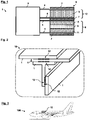
- figure 1 shows a schematic sectional view of a structural component 1 according to an embodiment of the invention.
- 2 shows the use of such a structural component 1 in a fastening arrangement 10 made up of a plurality of structural components 1.
- 3 is a side view of the corresponding aircraft 100, e.g. a passenger aircraft, with such a fastening arrangement 10.
- the structural component(s) 1 can in particular be structural components of a primary structure of the aircraft 100, such as load-bearing, connecting and/or stiffening elements of a fuselage and/or a wing spar, eg a frame, a stringer, a cross member, a beam , a skin field segment, a connector or the like. Even if with reference to 2 specific configurations of structural components 1 are shown, these are by no means limited to the exemplary embodiments shown. Rather, a wide variety of geometrically curved or non-curved shapes are conceivable, as are known to those skilled in the art from vehicle construction.
- the structural components 1 can be in the form of rods, optionally with a specific transverse profile such as L, T, Z, ⁇ , etc., or in the form of plates/flats.
- structural components 1, as described below, can be used not only in aircraft but also in general aircraft or other applications from the transport industry, for example in land, water or rail vehicles.
- the structural component 1 of 1 is manufactured as a fiber composite laminate 2 from a multiplicity of fiber composite layers, as is basically known to the person skilled in the art from aircraft construction for the production of structural components.
- the layers of this laminate structure form the supporting structure of component 1.
- the fiber composite laminate 2 in this exemplary case comprises, in particular, a plurality of fiber reinforcement layers 7 made from a glass fiber composite material.
- these layers have a structurally stabilizing effect.
- glass fibers in particular are electrically insulating and, in combination with a corresponding matrix material, can separate electrically conductive or functional layers of the fiber composite laminate 2, as described below, from one another.
- these fiber reinforcement layers 7 can in particular be permeable to electromagnetic radiation, which is advantageous for the energy transmission mechanism described further below.
- the fiber composite laminate 2 also includes a number of layers/plies that act as electrical transmitters 12 .
- the fiber composite laminate 2 specifically has a power transmission layer 3 in which one or more electromagnetic coils are integrated and which is designed to wirelessly transmit electrical energy by means of an electromagnetic alternating field.
- the fiber composite laminate 2 comprises a current-carrying layer 4 above and below the power transmission layer 3, each of which acts as an electrical contact for the power transmission layer 3 and connects it in interaction with a microcontroller, which is designed as a control device 5 to transmit electrical energy through the Power transmission layer 3 to regulate.
- the control device 5 can cause the power transmission layer 3 to transmit electrical power to an external receiver and to use electrical energy received from the latter.
- a structural component 1 which is capable of transporting electrical energy without additional cables, lines, plug connections or the like.
- an energy transmission device including a control and monitoring instance is integrated into the structural component 1 .
- an electrical infrastructure can be integrated directly into the supporting structure of the aircraft 100 without any cabling.
- the power transmission layers 3 of the structural components 1 can be arranged and formed relative to one another in such a way that electrical energy can be transmitted between the structural components 1 via the power transmission layers 3 .
- Such power transmission layers 3 can be used not only to exchange electrical energy, but also signals such as control signals or general data.
- the structural components 1 can thus in principle be used both for energy transmission and for data transmission.
- a lap joint of two plate-shaped structural components 1 can be seen (above in 2 ), On which a rod-shaped structural component 1 with a T-profile is placed vertically. Another rod-shaped structural component 1 is in turn connected to this structural component 1 in an overlapping manner. All of these structural components 1 are each formed with one or more of the electrical transmitters 12 described above, with two components each being joined to one another with opposite transmitters 12 so that electrical energy can be exchanged wirelessly in pairs.
- the structural components 1 can be glued together in the area of the transmitter 12, ie they can be connected to one another with a material fit.
- rivets or other structure-influencing connections can also be used outside of these areas.
- the power transmission layers 3 do not necessarily have to extend over the entire longitudinal and/or transverse extent of the structural component 1, but can only be provided in these in certain areas. It is thus possible to create certain flat contact areas for electrical contacting on the surfaces of the components 1.
- the structural components 1 can also be used as in 1 shown by way of example also be formed with an integrated electrical energy store 6, which stores electrical energy in a rechargeable manner.
- the electrical energy store 6 is coupled to both the control device 5 and the electrical transmitter 12 via corresponding power supply layers 4. so that energy received from the power transmission layer 3 can be used to charge the electrical energy store 6 and can also be made available by it for the power transmission layer 3 as required.
- the electrical energy store 6 is structurally integrated into the fiber composite laminate 2 as a multi-layer electrochemical fiber composite battery and is manufactured together with it. This means that the supporting structure of the aircraft 100 can not only store energy, but can also retrieve, transport and make it available for use, e.g. for electrical consumers in a passenger cabin, in a cockpit or in a cargo hold of the aircraft 100 and/or or for an electric drive of the aircraft 100.
- the electrical energy store 6 is designed as a functional fiber composite laminate in this example.
- Laminated composite structures consist of layers of orthotropic materials.
- Advantages of using fiber reinforced composites over conventional materials include lower dead weight, high specific strength, excellent fatigue strength, high stiffness-to-weight ratio and design flexibility.
- Structural batteries can, for example, have carbon fibers as an anode (e.g. embedded in a suitable binding polymer), a cathode made of coated Carbon fibers (e.g. LiFePO 4 coated, i.e. with particles based on lithium metal oxide, and also embedded in a corresponding structural electrolyte polymer), a separator with embedded glass fibers for separating the electrodes and for further transport of the ions, a suitable electrolyte material (e.g. a polymerized vinyl ester derivative of a poly (ethylene glycol) electrolytes) and current collectors or current collectors for connection to an external circuit (e.g. additively applied layers/coatings made of a metal material).
- anode e.g. embedded in a suitable binding polymer
- a cathode made of coated Carbon fibers (e.g. LiFePO 4 coated, i.e. with particles based on lithium metal oxide, and also embedded in a corresponding structural electrolyte polymer)
- Carbon fibers are particularly suitable as electrodes for structural composite batteries due to their mechanical properties and the easy incorporation of lithium ions. Carbon fibers have high stiffness and strength that provide mechanical reinforcement and favorable electrical conductivity for transporting electrons in and out of the battery (cell).
- the battery 6 comprises a stacked structure with an underlying anode layer 11, eg carbon fibers, embedded in a structural solid electrolyte (eg lithium-ion enriched synthetic resin).
- anode layer 11 On the anode layer 11 there is an electrolyte layer 9 containing glass fibers.
- an electrolyte layer 9 containing glass fibers.
- a cathode layer with carbon fibers eg LiFePO 4 coated and also embedded in a solid electrolyte.
- the two electrode layers 8, 11 are contacted by current-carrying layers 4, which can have a metal, for example, aluminum, copper foil, etc.
- the structural components 1 of the aircraft 100 can be provided with integrated energy storage capabilities (structure batteries) without the need for wiring or connections, since this can be regulated via the integrated energy transmission and suitable control and monitoring devices.
- This provides structural energy storage and supply with fast charging and discharging options and wireless energy transmission without connections, lines, cable harnesses and without the installation work that is usually associated with this during assembly.
Landscapes
- Engineering & Computer Science (AREA)
- Power Engineering (AREA)
- Mechanical Engineering (AREA)
- Aviation & Aerospace Engineering (AREA)
- Computer Networks & Wireless Communication (AREA)
- Laminated Bodies (AREA)
Applications Claiming Priority (1)
| Application Number | Priority Date | Filing Date | Title |
|---|---|---|---|
| DE102021102901.5A DE102021102901A1 (de) | 2021-02-08 | 2021-02-08 | Strukturbauteil für ein Fahrzeug und Befestigungsanordnung |
Publications (2)
| Publication Number | Publication Date |
|---|---|
| EP4040635A1 true EP4040635A1 (fr) | 2022-08-10 |
| EP4040635B1 EP4040635B1 (fr) | 2024-07-03 |
Family
ID=80625197
Family Applications (1)
| Application Number | Title | Priority Date | Filing Date |
|---|---|---|---|
| EP22153567.7A Active EP4040635B1 (fr) | 2021-02-08 | 2022-01-27 | Composant structural pour un véhicule et agencement de fixation |
Country Status (2)
| Country | Link |
|---|---|
| EP (1) | EP4040635B1 (fr) |
| DE (1) | DE102021102901A1 (fr) |
Cited By (1)
| Publication number | Priority date | Publication date | Assignee | Title |
|---|---|---|---|---|
| EP4503384A1 (fr) | 2023-08-03 | 2025-02-05 | Airbus S.A.S. | Composant d'aéronef à système électrique intégré |
Citations (6)
| Publication number | Priority date | Publication date | Assignee | Title |
|---|---|---|---|---|
| US20150061380A1 (en) * | 2013-08-30 | 2015-03-05 | Airbus Operations Gmbh | Floor system for a vehicle and a vehicle having a cabin and a floor made by such a floor system |
| EP3222514A1 (fr) * | 2016-03-21 | 2017-09-27 | Airbus Operations GmbH | Panneau de revêtement avec une couche de stockage d'énergie pour un avion ou un engin spatial et procédé de fabrication associé |
| US20180015705A1 (en) * | 2016-07-18 | 2018-01-18 | Airbus Operations Gmbh | Structural component forming an electrical power source, structural component with an electrical transmission device, method for providing a structural component forming an electrical power source and/or an electrical transmission device, electrical wiring system and aircraft component |
| EP2852990B1 (fr) | 2012-05-08 | 2018-01-31 | Battelle Memorial Institute | Cellule multifonction pour applications structurales |
| US10414358B2 (en) * | 2016-02-03 | 2019-09-17 | The Boeing Company | Composite panel power system |
| US20210037645A1 (en) * | 2019-06-14 | 2021-02-04 | Hutchinson Aeronautique & Industrie Ltée. | Composite panel comprising an integrated electrical circuit and manufacturing method thereof |
Family Cites Families (5)
| Publication number | Priority date | Publication date | Assignee | Title |
|---|---|---|---|---|
| US7349225B1 (en) * | 2002-10-22 | 2008-03-25 | Odyssian Technology, Llc | Multifunctional composite sandwich element with embedded electronics |
| US9362565B2 (en) | 2012-04-04 | 2016-06-07 | Nokia Technologies Oy | Apparatus and associated methods |
| US9660470B2 (en) | 2014-09-08 | 2017-05-23 | Nokia Technologies Oy | Flexible, hybrid energy generating and storage power cell |
| DE102017217642A1 (de) | 2017-10-05 | 2019-04-11 | Bayerische Motoren Werke Aktiengesellschaft | Spule mit Schutzbereich für induktives Laden |
| DE102018127044A1 (de) | 2018-10-30 | 2020-04-30 | Airbus Operations Gmbh | Verkleidungsbauteil für eine Kabine eines Transportmittels |
-
2021
- 2021-02-08 DE DE102021102901.5A patent/DE102021102901A1/de active Pending
-
2022
- 2022-01-27 EP EP22153567.7A patent/EP4040635B1/fr active Active
Patent Citations (6)
| Publication number | Priority date | Publication date | Assignee | Title |
|---|---|---|---|---|
| EP2852990B1 (fr) | 2012-05-08 | 2018-01-31 | Battelle Memorial Institute | Cellule multifonction pour applications structurales |
| US20150061380A1 (en) * | 2013-08-30 | 2015-03-05 | Airbus Operations Gmbh | Floor system for a vehicle and a vehicle having a cabin and a floor made by such a floor system |
| US10414358B2 (en) * | 2016-02-03 | 2019-09-17 | The Boeing Company | Composite panel power system |
| EP3222514A1 (fr) * | 2016-03-21 | 2017-09-27 | Airbus Operations GmbH | Panneau de revêtement avec une couche de stockage d'énergie pour un avion ou un engin spatial et procédé de fabrication associé |
| US20180015705A1 (en) * | 2016-07-18 | 2018-01-18 | Airbus Operations Gmbh | Structural component forming an electrical power source, structural component with an electrical transmission device, method for providing a structural component forming an electrical power source and/or an electrical transmission device, electrical wiring system and aircraft component |
| US20210037645A1 (en) * | 2019-06-14 | 2021-02-04 | Hutchinson Aeronautique & Industrie Ltée. | Composite panel comprising an integrated electrical circuit and manufacturing method thereof |
Cited By (1)
| Publication number | Priority date | Publication date | Assignee | Title |
|---|---|---|---|---|
| EP4503384A1 (fr) | 2023-08-03 | 2025-02-05 | Airbus S.A.S. | Composant d'aéronef à système électrique intégré |
Also Published As
| Publication number | Publication date |
|---|---|
| EP4040635B1 (fr) | 2024-07-03 |
| DE102021102901A1 (de) | 2022-08-11 |
Similar Documents
| Publication | Publication Date | Title |
|---|---|---|
| EP3544083B1 (fr) | Agencement de batterie permettant l'intégration structurelle des batteries dans un véhicule | |
| DE102012003309A1 (de) | Elektrisches Energiesystem in einem Kraftfahrzeug und Verfahren zum Betreiben eines Energiesystems | |
| EP3462525A1 (fr) | Enrobage de batteries structurelles | |
| DE102012214964A1 (de) | Batteriezelle, Batterie und Kraftfahrzeug | |
| EP4051579B1 (fr) | Structure légère pour véhicule et aéronef | |
| EP3561909A1 (fr) | Élément de structure avec un montage de batteries intégré | |
| EP4040635B1 (fr) | Composant structural pour un véhicule et agencement de fixation | |
| WO2012072437A1 (fr) | Cellule d'accumulateur à borne garnie d'un revêtement | |
| DE102020133854A1 (de) | Tragende Verbundschichtstoffstruktur für ein Luftfahrzeugbauteil, damit hergestelltes Luftfahrzeugbauteil und Luftfahrzeug | |
| DE102017128016A1 (de) | Batteriekern für ein Sandwichbauteil | |
| DE102012018158A1 (de) | Strukturbauteil, insbesondere für ein Luftfahrzeug, und Verfahren zum Herstellen eines Strukturbauteils | |
| EP3969274B1 (fr) | Stratifiés métal-fibres comprenant des fibres de carbone isolées électriquement | |
| DE102007012505A1 (de) | Fahrzeug mit kapazitivem Energiespeicher | |
| DE102021100713A1 (de) | Strukturbauteil für ein Fahrzeug | |
| EP3941831B1 (fr) | Dispositif d'affichage et procédé de production correspondant | |
| DE102022205481A1 (de) | Strukturbatterie für ein elektrofahrzeug | |
| DE102021124610A1 (de) | Batterie | |
| DE102014219991A1 (de) | Elektrisch angetriebenes Fahrzeug | |
| DE102021101976A1 (de) | Strukturbauteil für ein Fahrzeug | |
| DE102017111838A1 (de) | Faserverbundstruktur mit integrierter elektrochemischer Speicherfunktion für elektrische Energie | |
| DE102022003155A1 (de) | Fahrzeugbatterie | |
| DE102024200132A1 (de) | Vorrichtung sowie ein Bauteil mit einer entsprechenden Vorrichtung | |
| DE102012212937A1 (de) | Batterie mit mehreren elektrischen Energiespeichern und Verfahren zum Herstellen einer solchen Batterie | |
| DE102024003164A1 (de) | Elektrischer Energiespeicher und Verfahren zur Herstellung | |
| DE2357286C3 (de) | Elektromotorisch angetriebenes Fluggerät |
Legal Events
| Date | Code | Title | Description |
|---|---|---|---|
| PUAI | Public reference made under article 153(3) epc to a published international application that has entered the european phase |
Free format text: ORIGINAL CODE: 0009012 |
|
| STAA | Information on the status of an ep patent application or granted ep patent |
Free format text: STATUS: THE APPLICATION HAS BEEN PUBLISHED |
|
| AK | Designated contracting states |
Kind code of ref document: A1 Designated state(s): AL AT BE BG CH CY CZ DE DK EE ES FI FR GB GR HR HU IE IS IT LI LT LU LV MC MK MT NL NO PL PT RO RS SE SI SK SM TR |
|
| STAA | Information on the status of an ep patent application or granted ep patent |
Free format text: STATUS: REQUEST FOR EXAMINATION WAS MADE |
|
| 17P | Request for examination filed |
Effective date: 20230210 |
|
| RBV | Designated contracting states (corrected) |
Designated state(s): AL AT BE BG CH CY CZ DE DK EE ES FI FR GB GR HR HU IE IS IT LI LT LU LV MC MK MT NL NO PL PT RO RS SE SI SK SM TR |
|
| REG | Reference to a national code |
Ref country code: DE Ref legal event code: R079 Free format text: PREVIOUS MAIN CLASS: H02J0050100000 Ref country code: DE Ref legal event code: R079 Ref document number: 502022001139 Country of ref document: DE Free format text: PREVIOUS MAIN CLASS: H02J0050100000 Ipc: H02J0050000000 |
|
| REG | Reference to a national code |
Ref country code: DE Ref legal event code: R079 Ipc: B64C0001000000 Ref country code: DE Ref legal event code: R079 Ref document number: 502022001139 Country of ref document: DE Free format text: PREVIOUS MAIN CLASS: H02J0050000000 Ipc: B64C0001000000 |
|
| RIC1 | Information provided on ipc code assigned before grant |
Ipc: H02J 7/02 20160101ALI20231221BHEP Ipc: H02J 50/00 20160101AFI20231221BHEP |
|
| GRAP | Despatch of communication of intention to grant a patent |
Free format text: ORIGINAL CODE: EPIDOSNIGR1 |
|
| STAA | Information on the status of an ep patent application or granted ep patent |
Free format text: STATUS: GRANT OF PATENT IS INTENDED |
|
| RIC1 | Information provided on ipc code assigned before grant |
Ipc: B64C 1/00 20060101AFI20240110BHEP |
|
| INTG | Intention to grant announced |
Effective date: 20240201 |
|
| GRAS | Grant fee paid |
Free format text: ORIGINAL CODE: EPIDOSNIGR3 |
|
| GRAA | (expected) grant |
Free format text: ORIGINAL CODE: 0009210 |
|
| STAA | Information on the status of an ep patent application or granted ep patent |
Free format text: STATUS: THE PATENT HAS BEEN GRANTED |
|
| AK | Designated contracting states |
Kind code of ref document: B1 Designated state(s): AL AT BE BG CH CY CZ DE DK EE ES FI FR GB GR HR HU IE IS IT LI LT LU LV MC MK MT NL NO PL PT RO RS SE SI SK SM TR |
|
| REG | Reference to a national code |
Ref country code: CH Ref legal event code: EP |
|
| REG | Reference to a national code |
Ref country code: DE Ref legal event code: R096 Ref document number: 502022001139 Country of ref document: DE |
|
| REG | Reference to a national code |
Ref country code: LT Ref legal event code: MG9D |
|
| REG | Reference to a national code |
Ref country code: NL Ref legal event code: MP Effective date: 20240703 |
|
| PG25 | Lapsed in a contracting state [announced via postgrant information from national office to epo] |
Ref country code: PT Free format text: LAPSE BECAUSE OF FAILURE TO SUBMIT A TRANSLATION OF THE DESCRIPTION OR TO PAY THE FEE WITHIN THE PRESCRIBED TIME-LIMIT Effective date: 20241104 |
|
| PG25 | Lapsed in a contracting state [announced via postgrant information from national office to epo] |
Ref country code: NL Free format text: LAPSE BECAUSE OF FAILURE TO SUBMIT A TRANSLATION OF THE DESCRIPTION OR TO PAY THE FEE WITHIN THE PRESCRIBED TIME-LIMIT Effective date: 20240703 |
|
| PG25 | Lapsed in a contracting state [announced via postgrant information from national office to epo] |
Ref country code: PT Free format text: LAPSE BECAUSE OF FAILURE TO SUBMIT A TRANSLATION OF THE DESCRIPTION OR TO PAY THE FEE WITHIN THE PRESCRIBED TIME-LIMIT Effective date: 20241104 Ref country code: NL Free format text: LAPSE BECAUSE OF FAILURE TO SUBMIT A TRANSLATION OF THE DESCRIPTION OR TO PAY THE FEE WITHIN THE PRESCRIBED TIME-LIMIT Effective date: 20240703 |
|
| PG25 | Lapsed in a contracting state [announced via postgrant information from national office to epo] |
Ref country code: NO Free format text: LAPSE BECAUSE OF FAILURE TO SUBMIT A TRANSLATION OF THE DESCRIPTION OR TO PAY THE FEE WITHIN THE PRESCRIBED TIME-LIMIT Effective date: 20241003 |
|
| PG25 | Lapsed in a contracting state [announced via postgrant information from national office to epo] |
Ref country code: PL Free format text: LAPSE BECAUSE OF FAILURE TO SUBMIT A TRANSLATION OF THE DESCRIPTION OR TO PAY THE FEE WITHIN THE PRESCRIBED TIME-LIMIT Effective date: 20240703 Ref country code: FI Free format text: LAPSE BECAUSE OF FAILURE TO SUBMIT A TRANSLATION OF THE DESCRIPTION OR TO PAY THE FEE WITHIN THE PRESCRIBED TIME-LIMIT Effective date: 20240703 Ref country code: GR Free format text: LAPSE BECAUSE OF FAILURE TO SUBMIT A TRANSLATION OF THE DESCRIPTION OR TO PAY THE FEE WITHIN THE PRESCRIBED TIME-LIMIT Effective date: 20241004 |
|
| PG25 | Lapsed in a contracting state [announced via postgrant information from national office to epo] |
Ref country code: BG Free format text: LAPSE BECAUSE OF FAILURE TO SUBMIT A TRANSLATION OF THE DESCRIPTION OR TO PAY THE FEE WITHIN THE PRESCRIBED TIME-LIMIT Effective date: 20240703 |
|
| PG25 | Lapsed in a contracting state [announced via postgrant information from national office to epo] |
Ref country code: LV Free format text: LAPSE BECAUSE OF FAILURE TO SUBMIT A TRANSLATION OF THE DESCRIPTION OR TO PAY THE FEE WITHIN THE PRESCRIBED TIME-LIMIT Effective date: 20240703 |
|
| PG25 | Lapsed in a contracting state [announced via postgrant information from national office to epo] |
Ref country code: IS Free format text: LAPSE BECAUSE OF FAILURE TO SUBMIT A TRANSLATION OF THE DESCRIPTION OR TO PAY THE FEE WITHIN THE PRESCRIBED TIME-LIMIT Effective date: 20241103 |
|
| PG25 | Lapsed in a contracting state [announced via postgrant information from national office to epo] |
Ref country code: CZ Free format text: LAPSE BECAUSE OF FAILURE TO SUBMIT A TRANSLATION OF THE DESCRIPTION OR TO PAY THE FEE WITHIN THE PRESCRIBED TIME-LIMIT Effective date: 20240703 Ref country code: HR Free format text: LAPSE BECAUSE OF FAILURE TO SUBMIT A TRANSLATION OF THE DESCRIPTION OR TO PAY THE FEE WITHIN THE PRESCRIBED TIME-LIMIT Effective date: 20240703 |
|
| PG25 | Lapsed in a contracting state [announced via postgrant information from national office to epo] |
Ref country code: ES Free format text: LAPSE BECAUSE OF FAILURE TO SUBMIT A TRANSLATION OF THE DESCRIPTION OR TO PAY THE FEE WITHIN THE PRESCRIBED TIME-LIMIT Effective date: 20240703 Ref country code: RS Free format text: LAPSE BECAUSE OF FAILURE TO SUBMIT A TRANSLATION OF THE DESCRIPTION OR TO PAY THE FEE WITHIN THE PRESCRIBED TIME-LIMIT Effective date: 20241003 |
|
| PG25 | Lapsed in a contracting state [announced via postgrant information from national office to epo] |
Ref country code: RS Free format text: LAPSE BECAUSE OF FAILURE TO SUBMIT A TRANSLATION OF THE DESCRIPTION OR TO PAY THE FEE WITHIN THE PRESCRIBED TIME-LIMIT Effective date: 20241003 Ref country code: PL Free format text: LAPSE BECAUSE OF FAILURE TO SUBMIT A TRANSLATION OF THE DESCRIPTION OR TO PAY THE FEE WITHIN THE PRESCRIBED TIME-LIMIT Effective date: 20240703 Ref country code: NO Free format text: LAPSE BECAUSE OF FAILURE TO SUBMIT A TRANSLATION OF THE DESCRIPTION OR TO PAY THE FEE WITHIN THE PRESCRIBED TIME-LIMIT Effective date: 20241003 Ref country code: LV Free format text: LAPSE BECAUSE OF FAILURE TO SUBMIT A TRANSLATION OF THE DESCRIPTION OR TO PAY THE FEE WITHIN THE PRESCRIBED TIME-LIMIT Effective date: 20240703 Ref country code: IS Free format text: LAPSE BECAUSE OF FAILURE TO SUBMIT A TRANSLATION OF THE DESCRIPTION OR TO PAY THE FEE WITHIN THE PRESCRIBED TIME-LIMIT Effective date: 20241103 Ref country code: HR Free format text: LAPSE BECAUSE OF FAILURE TO SUBMIT A TRANSLATION OF THE DESCRIPTION OR TO PAY THE FEE WITHIN THE PRESCRIBED TIME-LIMIT Effective date: 20240703 Ref country code: GR Free format text: LAPSE BECAUSE OF FAILURE TO SUBMIT A TRANSLATION OF THE DESCRIPTION OR TO PAY THE FEE WITHIN THE PRESCRIBED TIME-LIMIT Effective date: 20241004 Ref country code: FI Free format text: LAPSE BECAUSE OF FAILURE TO SUBMIT A TRANSLATION OF THE DESCRIPTION OR TO PAY THE FEE WITHIN THE PRESCRIBED TIME-LIMIT Effective date: 20240703 Ref country code: ES Free format text: LAPSE BECAUSE OF FAILURE TO SUBMIT A TRANSLATION OF THE DESCRIPTION OR TO PAY THE FEE WITHIN THE PRESCRIBED TIME-LIMIT Effective date: 20240703 Ref country code: CZ Free format text: LAPSE BECAUSE OF FAILURE TO SUBMIT A TRANSLATION OF THE DESCRIPTION OR TO PAY THE FEE WITHIN THE PRESCRIBED TIME-LIMIT Effective date: 20240703 Ref country code: BG Free format text: LAPSE BECAUSE OF FAILURE TO SUBMIT A TRANSLATION OF THE DESCRIPTION OR TO PAY THE FEE WITHIN THE PRESCRIBED TIME-LIMIT Effective date: 20240703 |
|
| REG | Reference to a national code |
Ref country code: DE Ref legal event code: R097 Ref document number: 502022001139 Country of ref document: DE |
|
| PG25 | Lapsed in a contracting state [announced via postgrant information from national office to epo] |
Ref country code: RO Free format text: LAPSE BECAUSE OF FAILURE TO SUBMIT A TRANSLATION OF THE DESCRIPTION OR TO PAY THE FEE WITHIN THE PRESCRIBED TIME-LIMIT Effective date: 20240703 Ref country code: DK Free format text: LAPSE BECAUSE OF FAILURE TO SUBMIT A TRANSLATION OF THE DESCRIPTION OR TO PAY THE FEE WITHIN THE PRESCRIBED TIME-LIMIT Effective date: 20240703 Ref country code: SM Free format text: LAPSE BECAUSE OF FAILURE TO SUBMIT A TRANSLATION OF THE DESCRIPTION OR TO PAY THE FEE WITHIN THE PRESCRIBED TIME-LIMIT Effective date: 20240703 |
|
| PG25 | Lapsed in a contracting state [announced via postgrant information from national office to epo] |
Ref country code: EE Free format text: LAPSE BECAUSE OF FAILURE TO SUBMIT A TRANSLATION OF THE DESCRIPTION OR TO PAY THE FEE WITHIN THE PRESCRIBED TIME-LIMIT Effective date: 20240703 |
|
| PG25 | Lapsed in a contracting state [announced via postgrant information from national office to epo] |
Ref country code: SK Free format text: LAPSE BECAUSE OF FAILURE TO SUBMIT A TRANSLATION OF THE DESCRIPTION OR TO PAY THE FEE WITHIN THE PRESCRIBED TIME-LIMIT Effective date: 20240703 Ref country code: IT Free format text: LAPSE BECAUSE OF FAILURE TO SUBMIT A TRANSLATION OF THE DESCRIPTION OR TO PAY THE FEE WITHIN THE PRESCRIBED TIME-LIMIT Effective date: 20240703 |
|
| PLBE | No opposition filed within time limit |
Free format text: ORIGINAL CODE: 0009261 |
|
| STAA | Information on the status of an ep patent application or granted ep patent |
Free format text: STATUS: NO OPPOSITION FILED WITHIN TIME LIMIT |
|
| 26N | No opposition filed |
Effective date: 20250404 |
|
| REG | Reference to a national code |
Ref country code: CH Ref legal event code: PL |
|
| PG25 | Lapsed in a contracting state [announced via postgrant information from national office to epo] |
Ref country code: SE Free format text: LAPSE BECAUSE OF FAILURE TO SUBMIT A TRANSLATION OF THE DESCRIPTION OR TO PAY THE FEE WITHIN THE PRESCRIBED TIME-LIMIT Effective date: 20240703 |
|
| PG25 | Lapsed in a contracting state [announced via postgrant information from national office to epo] |
Ref country code: LU Free format text: LAPSE BECAUSE OF NON-PAYMENT OF DUE FEES Effective date: 20250127 Ref country code: MC Free format text: LAPSE BECAUSE OF FAILURE TO SUBMIT A TRANSLATION OF THE DESCRIPTION OR TO PAY THE FEE WITHIN THE PRESCRIBED TIME-LIMIT Effective date: 20240703 |
|
| PG25 | Lapsed in a contracting state [announced via postgrant information from national office to epo] |
Ref country code: BE Free format text: LAPSE BECAUSE OF NON-PAYMENT OF DUE FEES Effective date: 20250131 |
|
| PG25 | Lapsed in a contracting state [announced via postgrant information from national office to epo] |
Ref country code: CH Free format text: LAPSE BECAUSE OF NON-PAYMENT OF DUE FEES Effective date: 20250131 |
|
| REG | Reference to a national code |
Ref country code: BE Ref legal event code: MM Effective date: 20250131 |
|
| PG25 | Lapsed in a contracting state [announced via postgrant information from national office to epo] |
Ref country code: IE Free format text: LAPSE BECAUSE OF NON-PAYMENT OF DUE FEES Effective date: 20250127 |
|
| PGFP | Annual fee paid to national office [announced via postgrant information from national office to epo] |
Ref country code: GB Payment date: 20260123 Year of fee payment: 5 |
|
| PGFP | Annual fee paid to national office [announced via postgrant information from national office to epo] |
Ref country code: DE Payment date: 20260121 Year of fee payment: 5 |
|
| PGFP | Annual fee paid to national office [announced via postgrant information from national office to epo] |
Ref country code: AT Payment date: 20260301 Year of fee payment: 5 |
|
| PGFP | Annual fee paid to national office [announced via postgrant information from national office to epo] |
Ref country code: FR Payment date: 20260123 Year of fee payment: 5 |