EP2853324A2 - Procédé de création d'une texture de surface - Google Patents
Procédé de création d'une texture de surface Download PDFInfo
- Publication number
- EP2853324A2 EP2853324A2 EP14186346.4A EP14186346A EP2853324A2 EP 2853324 A2 EP2853324 A2 EP 2853324A2 EP 14186346 A EP14186346 A EP 14186346A EP 2853324 A2 EP2853324 A2 EP 2853324A2
- Authority
- EP
- European Patent Office
- Prior art keywords
- predetermined portion
- binder
- powder
- texture
- particular embodiment
- Prior art date
- Legal status (The legal status is an assumption and is not a legal conclusion. Google has not performed a legal analysis and makes no representation as to the accuracy of the status listed.)
- Withdrawn
Links
Images


Classifications
-
- B—PERFORMING OPERATIONS; TRANSPORTING
- B22—CASTING; POWDER METALLURGY
- B22F—WORKING METALLIC POWDER; MANUFACTURE OF ARTICLES FROM METALLIC POWDER; MAKING METALLIC POWDER; APPARATUS OR DEVICES SPECIALLY ADAPTED FOR METALLIC POWDER
- B22F5/00—Manufacture of workpieces or articles from metallic powder characterised by the special shape of the product
- B22F5/009—Manufacture of workpieces or articles from metallic powder characterised by the special shape of the product of turbine components other than turbine blades
-
- B—PERFORMING OPERATIONS; TRANSPORTING
- B22—CASTING; POWDER METALLURGY
- B22F—WORKING METALLIC POWDER; MANUFACTURE OF ARTICLES FROM METALLIC POWDER; MAKING METALLIC POWDER; APPARATUS OR DEVICES SPECIALLY ADAPTED FOR METALLIC POWDER
- B22F3/00—Manufacture of workpieces or articles from metallic powder characterised by the manner of compacting or sintering; Apparatus specially adapted therefor ; Presses and furnaces
- B22F3/12—Both compacting and sintering
-
- B—PERFORMING OPERATIONS; TRANSPORTING
- B22—CASTING; POWDER METALLURGY
- B22F—WORKING METALLIC POWDER; MANUFACTURE OF ARTICLES FROM METALLIC POWDER; MAKING METALLIC POWDER; APPARATUS OR DEVICES SPECIALLY ADAPTED FOR METALLIC POWDER
- B22F3/00—Manufacture of workpieces or articles from metallic powder characterised by the manner of compacting or sintering; Apparatus specially adapted therefor ; Presses and furnaces
- B22F3/22—Manufacture of workpieces or articles from metallic powder characterised by the manner of compacting or sintering; Apparatus specially adapted therefor ; Presses and furnaces for producing castings from a slip
- B22F3/225—Manufacture of workpieces or articles from metallic powder characterised by the manner of compacting or sintering; Apparatus specially adapted therefor ; Presses and furnaces for producing castings from a slip by injection molding
-
- B—PERFORMING OPERATIONS; TRANSPORTING
- B22—CASTING; POWDER METALLURGY
- B22F—WORKING METALLIC POWDER; MANUFACTURE OF ARTICLES FROM METALLIC POWDER; MAKING METALLIC POWDER; APPARATUS OR DEVICES SPECIALLY ADAPTED FOR METALLIC POWDER
- B22F3/00—Manufacture of workpieces or articles from metallic powder characterised by the manner of compacting or sintering; Apparatus specially adapted therefor ; Presses and furnaces
- B22F3/24—After-treatment of workpieces or articles
-
- B—PERFORMING OPERATIONS; TRANSPORTING
- B22—CASTING; POWDER METALLURGY
- B22F—WORKING METALLIC POWDER; MANUFACTURE OF ARTICLES FROM METALLIC POWDER; MAKING METALLIC POWDER; APPARATUS OR DEVICES SPECIALLY ADAPTED FOR METALLIC POWDER
- B22F5/00—Manufacture of workpieces or articles from metallic powder characterised by the special shape of the product
- B22F5/10—Manufacture of workpieces or articles from metallic powder characterised by the special shape of the product of articles with cavities or holes, not otherwise provided for in the preceding subgroups
-
- C—CHEMISTRY; METALLURGY
- C04—CEMENTS; CONCRETE; ARTIFICIAL STONE; CERAMICS; REFRACTORIES
- C04B—LIME, MAGNESIA; SLAG; CEMENTS; COMPOSITIONS THEREOF, e.g. MORTARS, CONCRETE OR LIKE BUILDING MATERIALS; ARTIFICIAL STONE; CERAMICS; REFRACTORIES; TREATMENT OF NATURAL STONE
- C04B35/00—Shaped ceramic products characterised by their composition; Ceramics compositions; Processing powders of inorganic compounds preparatory to the manufacturing of ceramic products
- C04B35/622—Forming processes; Processing powders of inorganic compounds preparatory to the manufacturing of ceramic products
- C04B35/626—Preparing or treating the powders individually or as batches ; preparing or treating macroscopic reinforcing agents for ceramic products, e.g. fibres; mechanical aspects section B
- C04B35/63—Preparing or treating the powders individually or as batches ; preparing or treating macroscopic reinforcing agents for ceramic products, e.g. fibres; mechanical aspects section B using additives specially adapted for forming the products, e.g.. binder binders
- C04B35/638—Removal thereof
-
- B—PERFORMING OPERATIONS; TRANSPORTING
- B22—CASTING; POWDER METALLURGY
- B22F—WORKING METALLIC POWDER; MANUFACTURE OF ARTICLES FROM METALLIC POWDER; MAKING METALLIC POWDER; APPARATUS OR DEVICES SPECIALLY ADAPTED FOR METALLIC POWDER
- B22F5/00—Manufacture of workpieces or articles from metallic powder characterised by the special shape of the product
- B22F2005/005—Article surface comprising protrusions
-
- B—PERFORMING OPERATIONS; TRANSPORTING
- B22—CASTING; POWDER METALLURGY
- B22F—WORKING METALLIC POWDER; MANUFACTURE OF ARTICLES FROM METALLIC POWDER; MAKING METALLIC POWDER; APPARATUS OR DEVICES SPECIALLY ADAPTED FOR METALLIC POWDER
- B22F2998/00—Supplementary information concerning processes or compositions relating to powder metallurgy
- B22F2998/10—Processes characterised by the sequence of their steps
-
- B—PERFORMING OPERATIONS; TRANSPORTING
- B22—CASTING; POWDER METALLURGY
- B22F—WORKING METALLIC POWDER; MANUFACTURE OF ARTICLES FROM METALLIC POWDER; MAKING METALLIC POWDER; APPARATUS OR DEVICES SPECIALLY ADAPTED FOR METALLIC POWDER
- B22F2999/00—Aspects linked to processes or compositions used in powder metallurgy
-
- C—CHEMISTRY; METALLURGY
- C04—CEMENTS; CONCRETE; ARTIFICIAL STONE; CERAMICS; REFRACTORIES
- C04B—LIME, MAGNESIA; SLAG; CEMENTS; COMPOSITIONS THEREOF, e.g. MORTARS, CONCRETE OR LIKE BUILDING MATERIALS; ARTIFICIAL STONE; CERAMICS; REFRACTORIES; TREATMENT OF NATURAL STONE
- C04B2235/00—Aspects relating to ceramic starting mixtures or sintered ceramic products
- C04B2235/02—Composition of constituents of the starting material or of secondary phases of the final product
- C04B2235/50—Constituents or additives of the starting mixture chosen for their shape or used because of their shape or their physical appearance
- C04B2235/54—Particle size related information
- C04B2235/5418—Particle size related information expressed by the size of the particles or aggregates thereof
- C04B2235/5436—Particle size related information expressed by the size of the particles or aggregates thereof micrometer sized, i.e. from 1 to 100 micron
-
- C—CHEMISTRY; METALLURGY
- C04—CEMENTS; CONCRETE; ARTIFICIAL STONE; CERAMICS; REFRACTORIES
- C04B—LIME, MAGNESIA; SLAG; CEMENTS; COMPOSITIONS THEREOF, e.g. MORTARS, CONCRETE OR LIKE BUILDING MATERIALS; ARTIFICIAL STONE; CERAMICS; REFRACTORIES; TREATMENT OF NATURAL STONE
- C04B2235/00—Aspects relating to ceramic starting mixtures or sintered ceramic products
- C04B2235/02—Composition of constituents of the starting material or of secondary phases of the final product
- C04B2235/50—Constituents or additives of the starting mixture chosen for their shape or used because of their shape or their physical appearance
- C04B2235/54—Particle size related information
- C04B2235/5418—Particle size related information expressed by the size of the particles or aggregates thereof
- C04B2235/5445—Particle size related information expressed by the size of the particles or aggregates thereof submicron sized, i.e. from 0,1 to 1 micron
-
- C—CHEMISTRY; METALLURGY
- C04—CEMENTS; CONCRETE; ARTIFICIAL STONE; CERAMICS; REFRACTORIES
- C04B—LIME, MAGNESIA; SLAG; CEMENTS; COMPOSITIONS THEREOF, e.g. MORTARS, CONCRETE OR LIKE BUILDING MATERIALS; ARTIFICIAL STONE; CERAMICS; REFRACTORIES; TREATMENT OF NATURAL STONE
- C04B2235/00—Aspects relating to ceramic starting mixtures or sintered ceramic products
- C04B2235/60—Aspects relating to the preparation, properties or mechanical treatment of green bodies or pre-forms
- C04B2235/602—Making the green bodies or pre-forms by moulding
- C04B2235/6022—Injection moulding
-
- C—CHEMISTRY; METALLURGY
- C04—CEMENTS; CONCRETE; ARTIFICIAL STONE; CERAMICS; REFRACTORIES
- C04B—LIME, MAGNESIA; SLAG; CEMENTS; COMPOSITIONS THEREOF, e.g. MORTARS, CONCRETE OR LIKE BUILDING MATERIALS; ARTIFICIAL STONE; CERAMICS; REFRACTORIES; TREATMENT OF NATURAL STONE
- C04B2235/00—Aspects relating to ceramic starting mixtures or sintered ceramic products
- C04B2235/65—Aspects relating to heat treatments of ceramic bodies such as green ceramics or pre-sintered ceramics, e.g. burning, sintering or melting processes
- C04B2235/66—Specific sintering techniques, e.g. centrifugal sintering
- C04B2235/665—Local sintering, e.g. laser sintering
-
- C—CHEMISTRY; METALLURGY
- C04—CEMENTS; CONCRETE; ARTIFICIAL STONE; CERAMICS; REFRACTORIES
- C04B—LIME, MAGNESIA; SLAG; CEMENTS; COMPOSITIONS THEREOF, e.g. MORTARS, CONCRETE OR LIKE BUILDING MATERIALS; ARTIFICIAL STONE; CERAMICS; REFRACTORIES; TREATMENT OF NATURAL STONE
- C04B2235/00—Aspects relating to ceramic starting mixtures or sintered ceramic products
- C04B2235/70—Aspects relating to sintered or melt-casted ceramic products
- C04B2235/94—Products characterised by their shape
- C04B2235/945—Products containing grooves, cuts, recesses or protusions
-
- C—CHEMISTRY; METALLURGY
- C04—CEMENTS; CONCRETE; ARTIFICIAL STONE; CERAMICS; REFRACTORIES
- C04B—LIME, MAGNESIA; SLAG; CEMENTS; COMPOSITIONS THEREOF, e.g. MORTARS, CONCRETE OR LIKE BUILDING MATERIALS; ARTIFICIAL STONE; CERAMICS; REFRACTORIES; TREATMENT OF NATURAL STONE
- C04B2235/00—Aspects relating to ceramic starting mixtures or sintered ceramic products
- C04B2235/70—Aspects relating to sintered or melt-casted ceramic products
- C04B2235/96—Properties of ceramic products, e.g. mechanical properties such as strength, toughness, wear resistance
- C04B2235/963—Surface properties, e.g. surface roughness
-
- C—CHEMISTRY; METALLURGY
- C04—CEMENTS; CONCRETE; ARTIFICIAL STONE; CERAMICS; REFRACTORIES
- C04B—LIME, MAGNESIA; SLAG; CEMENTS; COMPOSITIONS THEREOF, e.g. MORTARS, CONCRETE OR LIKE BUILDING MATERIALS; ARTIFICIAL STONE; CERAMICS; REFRACTORIES; TREATMENT OF NATURAL STONE
- C04B2237/00—Aspects relating to ceramic laminates or to joining of ceramic articles with other articles by heating
- C04B2237/50—Processing aspects relating to ceramic laminates or to the joining of ceramic articles with other articles by heating
- C04B2237/62—Forming laminates or joined articles comprising holes, channels or other types of openings
-
- C—CHEMISTRY; METALLURGY
- C04—CEMENTS; CONCRETE; ARTIFICIAL STONE; CERAMICS; REFRACTORIES
- C04B—LIME, MAGNESIA; SLAG; CEMENTS; COMPOSITIONS THEREOF, e.g. MORTARS, CONCRETE OR LIKE BUILDING MATERIALS; ARTIFICIAL STONE; CERAMICS; REFRACTORIES; TREATMENT OF NATURAL STONE
- C04B2237/00—Aspects relating to ceramic laminates or to joining of ceramic articles with other articles by heating
- C04B2237/50—Processing aspects relating to ceramic laminates or to the joining of ceramic articles with other articles by heating
- C04B2237/64—Forming laminates or joined articles comprising grooves or cuts
-
- F—MECHANICAL ENGINEERING; LIGHTING; HEATING; WEAPONS; BLASTING
- F01—MACHINES OR ENGINES IN GENERAL; ENGINE PLANTS IN GENERAL; STEAM ENGINES
- F01D—NON-POSITIVE DISPLACEMENT MACHINES OR ENGINES, e.g. STEAM TURBINES
- F01D11/00—Preventing or minimising internal leakage of working-fluid, e.g. between stages
- F01D11/08—Preventing or minimising internal leakage of working-fluid, e.g. between stages for sealing space between rotor blade tips and stator
- F01D11/14—Adjusting or regulating tip-clearance, i.e. distance between rotor-blade tips and stator casing
- F01D11/20—Actively adjusting tip-clearance
- F01D11/24—Actively adjusting tip-clearance by selectively cooling-heating stator or rotor components
-
- F—MECHANICAL ENGINEERING; LIGHTING; HEATING; WEAPONS; BLASTING
- F05—INDEXING SCHEMES RELATING TO ENGINES OR PUMPS IN VARIOUS SUBCLASSES OF CLASSES F01-F04
- F05D—INDEXING SCHEME FOR ASPECTS RELATING TO NON-POSITIVE-DISPLACEMENT MACHINES OR ENGINES, GAS-TURBINES OR JET-PROPULSION PLANTS
- F05D2240/00—Components
- F05D2240/10—Stators
- F05D2240/11—Shroud seal segments
-
- F—MECHANICAL ENGINEERING; LIGHTING; HEATING; WEAPONS; BLASTING
- F05—INDEXING SCHEMES RELATING TO ENGINES OR PUMPS IN VARIOUS SUBCLASSES OF CLASSES F01-F04
- F05D—INDEXING SCHEME FOR ASPECTS RELATING TO NON-POSITIVE-DISPLACEMENT MACHINES OR ENGINES, GAS-TURBINES OR JET-PROPULSION PLANTS
- F05D2250/00—Geometry
- F05D2250/20—Three-dimensional
- F05D2250/22—Three-dimensional parallelepipedal
- F05D2250/221—Three-dimensional parallelepipedal cubic
-
- F—MECHANICAL ENGINEERING; LIGHTING; HEATING; WEAPONS; BLASTING
- F05—INDEXING SCHEMES RELATING TO ENGINES OR PUMPS IN VARIOUS SUBCLASSES OF CLASSES F01-F04
- F05D—INDEXING SCHEME FOR ASPECTS RELATING TO NON-POSITIVE-DISPLACEMENT MACHINES OR ENGINES, GAS-TURBINES OR JET-PROPULSION PLANTS
- F05D2250/00—Geometry
- F05D2250/20—Three-dimensional
- F05D2250/29—Three-dimensional machined; miscellaneous
- F05D2250/294—Three-dimensional machined; miscellaneous grooved
-
- F—MECHANICAL ENGINEERING; LIGHTING; HEATING; WEAPONS; BLASTING
- F05—INDEXING SCHEMES RELATING TO ENGINES OR PUMPS IN VARIOUS SUBCLASSES OF CLASSES F01-F04
- F05D—INDEXING SCHEME FOR ASPECTS RELATING TO NON-POSITIVE-DISPLACEMENT MACHINES OR ENGINES, GAS-TURBINES OR JET-PROPULSION PLANTS
- F05D2260/00—Function
- F05D2260/20—Heat transfer, e.g. cooling
- F05D2260/201—Heat transfer, e.g. cooling by impingement of a fluid
-
- F—MECHANICAL ENGINEERING; LIGHTING; HEATING; WEAPONS; BLASTING
- F05—INDEXING SCHEMES RELATING TO ENGINES OR PUMPS IN VARIOUS SUBCLASSES OF CLASSES F01-F04
- F05D—INDEXING SCHEME FOR ASPECTS RELATING TO NON-POSITIVE-DISPLACEMENT MACHINES OR ENGINES, GAS-TURBINES OR JET-PROPULSION PLANTS
- F05D2260/00—Function
- F05D2260/20—Heat transfer, e.g. cooling
- F05D2260/221—Improvement of heat transfer
- F05D2260/2212—Improvement of heat transfer by creating turbulence
-
- F—MECHANICAL ENGINEERING; LIGHTING; HEATING; WEAPONS; BLASTING
- F05—INDEXING SCHEMES RELATING TO ENGINES OR PUMPS IN VARIOUS SUBCLASSES OF CLASSES F01-F04
- F05D—INDEXING SCHEME FOR ASPECTS RELATING TO NON-POSITIVE-DISPLACEMENT MACHINES OR ENGINES, GAS-TURBINES OR JET-PROPULSION PLANTS
- F05D2260/00—Function
- F05D2260/20—Heat transfer, e.g. cooling
- F05D2260/221—Improvement of heat transfer
- F05D2260/2214—Improvement of heat transfer by increasing the heat transfer surface
-
- F—MECHANICAL ENGINEERING; LIGHTING; HEATING; WEAPONS; BLASTING
- F05—INDEXING SCHEMES RELATING TO ENGINES OR PUMPS IN VARIOUS SUBCLASSES OF CLASSES F01-F04
- F05D—INDEXING SCHEME FOR ASPECTS RELATING TO NON-POSITIVE-DISPLACEMENT MACHINES OR ENGINES, GAS-TURBINES OR JET-PROPULSION PLANTS
- F05D2260/00—Function
- F05D2260/20—Heat transfer, e.g. cooling
- F05D2260/221—Improvement of heat transfer
- F05D2260/2214—Improvement of heat transfer by increasing the heat transfer surface
- F05D2260/22141—Improvement of heat transfer by increasing the heat transfer surface using fins or ribs
-
- Y—GENERAL TAGGING OF NEW TECHNOLOGICAL DEVELOPMENTS; GENERAL TAGGING OF CROSS-SECTIONAL TECHNOLOGIES SPANNING OVER SEVERAL SECTIONS OF THE IPC; TECHNICAL SUBJECTS COVERED BY FORMER USPC CROSS-REFERENCE ART COLLECTIONS [XRACs] AND DIGESTS
- Y02—TECHNOLOGIES OR APPLICATIONS FOR MITIGATION OR ADAPTATION AGAINST CLIMATE CHANGE
- Y02P—CLIMATE CHANGE MITIGATION TECHNOLOGIES IN THE PRODUCTION OR PROCESSING OF GOODS
- Y02P10/00—Technologies related to metal processing
- Y02P10/25—Process efficiency
Definitions
- the application relates generally to the creation of a surface texture in a part and, more particularly, to the creation of surface texture in parts manufactured by a powder injection molding process.
- Cooling features such as pins or fins are often used in various types of parts, for example in shroud segments or heat shields of gas turbine engines, to help lower the surface temperature of the parts.
- such features may be difficult to machine in a part, particularly when the part is manufactured from hard alloys. Accordingly, it has been known to mold the cooling features with the part.
- the molding process may be limited as to the size of the features it can produce, including cooling features or similar texture in a surface. In addition, depending on their location, creating the features through molding may not always be possible.
- a method of creating a texture on at least one surface of a part comprising: a) providing a solid green part made from a feedstock including powder and a binder; b) after step a), changing a physical state of the binder in only a predetermined portion of each of the at least one surface of the part and; c) after step b), defining the texture from the predetermined portion by debinding and sintering the part.
- a method of creating a texture on at least one surface of a part comprising: a) molding the part from a feedstock including a powder remaining solid during molding and a binder, including solidifying the molded part; b) after step a), changing a physical state of the binder in only a predetermined portion of each of the at least one surface of the part; and c) after step b), defining the texture from the predetermined portion by debinding and sintering the part.
- a method of creating a texture on a part comprising: providing a solid green part made from a feedstock including a binder; melting or vaporizing the binder in only a predetermined portion of at least one surface of the green part while the binder in a remainder of the green part remains solid; and after the binder is melted or vaporized in the predetermined portion, debinding and sintering the part, the predetermined portion after debinding and sintering defining the texture on the at least one surface.
- a method of creating a surface texture on a part particularly a part formed through a powder injection molding process, which in a particular embodiment is a metal injection molding process (MIM).
- MIM metal injection molding process
- the texture is created by acting on the binder of the green part.
- An exemplary part is provided herein as a component of a gas turbine engine.
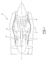
- Fig.1 illustrates a gas turbine engine 10 of a type preferably provided for use in subsonic flight, generally comprising in serial flow communication a fan 12 through which ambient air is propelled, a compressor section 14 for pressurizing the air, a combustor 16 in which the compressed air is mixed with fuel and ignited for generating an annular stream of hot combustion gases, and a turbine section 18 for extracting energy from the combustion gases.
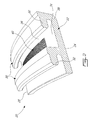
- the part on which a textured surface is provided is a shroud segment 20 of a gas turbine engine such as that shown in Fig. 1 .
- the shroud segment 20 is one of a plurality of similar or identical circumferentially adjoining shroud segments together defining a stationary annular turbine shroud concentrically arranged around the periphery of the blade tips of a turbine rotor of a high pressure stage of the turbine section 18.
- the turbine shroud defines a portion of the radially outer boundary of the engine gas path.
- each shroud segment 20 is individually supported and located within the engine 10 by an outer housing support structure so as to collectively form a continuous shroud ring about the turbine blades.
- the shroud segment 20 includes an arcuate platform 22 having an inner gas path surface 24 which is adapted to be exposed to the hot combustion gases during engine operation and an opposed outer cold surface 26.
- the platform 22 extends between circumferentially opposed ends 28 which mate with the circumferential end of the abutting shroud segments to form the shroud.
- Axially spaced-apart front and rear legs 30 extend radially outwardly from the outer surface 26 of the platform 22.
- the legs 30 are each provided with a respective axially projecting hook or rail portion 32 for engagement with corresponding mounting flange projections of the surrounding support structure in the engine.
- a shroud plenum 34 is defined between the legs 30 and between the outer surface 26 of the platform 22 and the support structure, for receiving cooling air from a cooling air source, for example bleed air from the compressor 14.
- various recesses or slots may be defined in the shroud segment 20, for example for receiving sealing members therein, including, but not limited to, radially extending slots in the legs 30, in the side of the legs facing the plenum 34, and/or in the circumferential ends 28 of the platform.
- Other features may be provided in the shroud segment 20, including, but not limited to, cooling holes, angular timing features, clamping pockets, and platforms.
- a portion of the outer surface 26 of the platform 22 is provided with a surface texture 40, which in a particular embodiment increases its surface area and accordingly its heat transfer properties to increase cooling.
- the shroud segment 20 shown herein is an exemplary embodiment and that the part may alternately be any other component requiring a surface texture 40 and which may be manufactured from a powder injection molding process or any other process creating an intermediary green part, i.e. a part including a solidified binder that holds a material powder together with the binder being removed before the part is in its final form.
- the part may be a heat shield of the gas turbine engine 10, used for example to protect a portion of a wall of the combustor 16.
- the increase of surface area caused by the presence of the texture on the surface of the part may allow for increased heat transfer properties, increased abradability, reduced friction, improved lubrication, and/or improved aerodynamic properties.
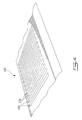
- a surface texture 40 which can be applied for example to the outer surface 26 of the platform 22 or to any other adequate type of part, is shown.
- the surface texture 40 is formed by a first set of regularly spaced apart linear grooves 50, which extend e.g. along the circumferential direction of the platform, and a second set of regularly spaced apart linear grooves 52, which extend e.g. along the axial direction of the platform, and which intersect the grooves 50 of the first set in a perpendicular manner. Together, the two sets of grooves 50, 52 thus define a series of pins 54 extending therebetween in a grid-type pattern.
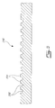
- the surface texture 140 is defined by a single set of regularly spaced apart linear grooves 150, which extend e.g. along the circumferential direction of the platform.
- a series of regularly spaced-apart linear fins 154 is thus defined between the grooves 150.
- the surface texture 40, 140 of the part is created in accordance with the following method 100.
- a green part is first provided in its solid state, manufactured without the desired texture of its surface(s).
- the green part is formed by injection molding of a feedstock, which is a homogeneous mixture of an injection powder (metal, ceramic, glass, carbide) with a binder.
- the injection powder may have a mean particle size generally varying in a range from about 100 ⁇ m to about 0.1 ⁇ m, and more particularly 50 ⁇ m to about 0.1 ⁇ m.
- the percentage injection powder to total feedstock is in a range from 30 to 80% powder solids by volume of the total feedstock mixture, and preferably above 50% powder solids by volume of total feedstock mixture.
- the green part includes two or more green parts molded separately and assembled while still in the green state, as described in application No. 12/408,078 filed March 20, 2009 and published as US 2010-0236688 A1 , which is incorporated by reference herein.
- the injection powder is a metal, such as nickel superalloy.
- metals include, but are not limited to, steel based alloys, other nickel based alloys, cobalt based alloys, titanium, copper, and other types of superalloys.
- the binder includes a mix of thermoplastic polymers and is composed in majority of wax, and may include surfactants and other additives.
- the binder is typically an organic material which is molten above room temperature but solid or substantially solid (herein referred to as "solid") at room temperature.
- the binder may include various components such as lubricants and/or surfactants, and may include a mixture of a lower and a higher melting temperature polymer or polymers.
- binders include, but are not limited to, polypropylene (PP), polyethylene (PE), polystyrene (PS), polyvinyl Chloride (PVC), paraffin Wax 60 (PW), polyethylene glycol 65 (PEG), microcrystalline wax 70 (MW), and combinations thereof.
- the injection powder is mixed with the molten binder and the suspension of injection powder and binder is injected into a mold and cooled to a temperature below that of the melting point of the binder.
- the green part is composed of two or more green parts molded separately, allowed to cool and then assembled while in the green state
- the green parts may be manufactured using different injections powders for individual green parts. Alternately, all green parts may be manufactured using the same injection powder.
- the green parts may be connected using permanent or non-permanent type connections, which may be substantially hermetic (substantially airtight or sealed) or not, and which may be formed by threaded engagement, through mechanical connectors made of feedstock or filler feedstock including but not limited to bolts, clips, clamps, couplings, lugs, pins and rivets, through the addition of a small amount of molten feedstock to the junction between the parts, through heating one or more of the parts near the junction to locally melt the binder, through heating one or more of the parts at the junction to locally soften the binder without melting it, by using a melted filler feedstock as a glue at the junction between the parts, etc.
- the filler feedstock may have a different binder than that used in the green part such as to have a lower melting point to be liquid or paste-like at a temperature where the green parts remain solid.
- the physical state of the binder of the green part in its solidified state is changed in only a predetermined portion of each surface on which a texture is desired, as set forth in step 104.
- this may be performed either before or after the two or more green parts are interconnected.
- the configuration of the predetermined portion is selected in accordance with the desired surface texture in the final part.
- the predetermined portion may include two series of lines crossing each other in a perpendicular manner, with the lines of a same one of the series being parallel, in correspondence with the grooves 50, 52; for a textured pattern such as that shown in Figs. 4-5 , the predetermined portion may include a set of parallel lines, in correspondence with the grooves 150; for a desired surface pattern including circular pins, the predetermined portion may include a plurality of spaced apart rings such that the pins will be defined at their center; etc.
- the predetermined portion corresponds to a marking of the position of the indented features of the desired surface pattern.
- predetermined portion examples include lines or linear features having an orientation following the direction of the cooling air, including for example circular patterns on the surface 26 in alignment with impingement holes in the turbine case, such as to create cooling fins perpendicular to the direction of the flow of the cooling air.
- Other possible configurations include, but are not limited to, various types of hatch patterns and a rasterized arbitrary image created on the surface.
- a texture may be visible on the surface of the green part; in a particular embodiment, this texture is different from that obtained in the finished part.
- the size and/or shape of the elements forming the texture e.g. depth of grooves, size and/or shape of pins
- changing the physical state of the binder in the predetermined portion includes melting and/or vaporizing the binder in the predetermined portion, while the remainder of the binder remains solid.
- the state of the binder in the predetermined portion is changed through local heating of only the predetermined portion at a temperature at least equal to the melting temperature of the binder.
- the predetermined portion is heated at a temperature at least equal to the boiling temperature of the binder.
- the local heating is performed at a temperature selected to avoid local sintering or chemical alteration of the injection (e.g. metal) powder. Alternately, some local sintering may occur.
- the injection powder in the predetermined portion may be displaced, for example through the force of the reaction in the binder (e.g. explosive escape of volatile vapors created during vaporization of the binder), and/or as a consequence of the method used to provide heat to the binder (e.g. heated air as further detailed below).
- the displacement of the injection powder in the predetermined portion contributes to the creation of the surface texture on the finished part.
- the solid loading in the predetermined portion may be changed, for example through variations in the powder to binder ratio caused by the melting and/or evaporation of the binder in the predetermined portion.
- the changed in solid loading in the predetermined portion contributes to the creation of the surface texture on the finished part.
- the predetermined portion may be locally heated through radiation.
- the predetermined portion is heated using a laser, for example a marking laser such a 20W ytterbium laser marking system.
- a laser for example a marking laser such a 20W ytterbium laser marking system.
- the parameters of the laser e.g. power, frequency of pulses, focal point, wobble
- the parameters of the laser are selected to produce local heating of the binder in the predetermined portion to at least its melting temperature, and preferably to a temperature lower than that producing sintering of the injection powder.
- the laser is configured such as to be out of focus with the heated surface, to produce a more diffuse heating over a larger area.
- the use of a laser allows for the creation of complex patterns in a comparatively short time.
- Alternate methods of heating the predetermined portion include, but are not limited to, directing a small jet of heated air on the predetermined portion using a micro heat gun, where the jet of air is preferably configured to control the displacement of the injection powder caused thereby; and physical contact of a heated element (e.g. wire mesh element) with the predetermined portion, where the heated element is preferably configured to limit the amount of feedstock remaining stuck on the heated element when it is disengaged from the predetermined portion.
- a heated element e.g. wire mesh element
- changing the state of the binder includes mechanisms other than melting and vaporization, including for example decomposition, oxidation, combustion, and combinations thereof, which may occur together with melting and/or vaporization.
- a brown part as discussed herein refers to a porous and friable part that is usually defined by an almost complete absence of binder.
- the brown part may be held together by some pre-sintered injection powder particles linked through a weak interaction between spaces formed at points where the binder was originally found, and/or by a residual amount of binder remaining after the debinding process.
- Debinding is typically done by heating, dissolution with a solvent, or decomposition.
- the debinding process is performed by heating the green part supported by a particulate shape retaining media to minimize deformation; the particulate media is easily wetted by the binder in order to allow for wicking of the binder to take place.
- the particulate media is alumina (Al 2 O 3 ).
- other particulate shape retaining media may also be used, including but not limited to CaO, MgO, zeolites, bentonite, clays, other metal oxides (TiO 2 , ZrO 2 ), SiO 2 , and combinations thereof.
- the binder melts and becomes liquid, and the particulate shape retaining media wicks the molten liquid binder away from the green part within itself.
- the ramp rate for the temperature is selected such as to avoid immediate vaporization of the binder to limit deformation of the part which could be caused by explosive escape of volatile vapors therefrom.
- the temperatures and ramp rates depend on the binder used. When the majority of the binder is removed as a liquid, the remaining binder may be heated at a faster rate for partial or full vaporization.
- the brown part is then heated to be sintered, as shown in step 108, to obtain the final part with its surface texture.
- the sintering process includes heating the brown part to a temperature below the melting point of the injection powder (e.g. metal powder), and preferably above one half the melting point in degrees Kelvin. Heating may be performed with one or more dwell(s), and in a particular embodiment is performed with the part being free of the particulate media.
- the final surface texture of the part is created during the debinding and/or sintering process from the predetermined portions, for example due to the injection powder displaced during the change of state of the binder in the predetermined portion of the green part and/or the variation of solid loading present in the predetermined portion as compared to that in the remainder of the part.
Landscapes
- Engineering & Computer Science (AREA)
- Manufacturing & Machinery (AREA)
- Mechanical Engineering (AREA)
- Chemical & Material Sciences (AREA)
- Ceramic Engineering (AREA)
- Inorganic Chemistry (AREA)
- Materials Engineering (AREA)
- Structural Engineering (AREA)
- Organic Chemistry (AREA)
- Powder Metallurgy (AREA)
Applications Claiming Priority (1)
| Application Number | Priority Date | Filing Date | Title |
|---|---|---|---|
| US14/039,336 US20150093281A1 (en) | 2013-09-27 | 2013-09-27 | Method of Creating a Surface Texture |
Publications (2)
| Publication Number | Publication Date |
|---|---|
| EP2853324A2 true EP2853324A2 (fr) | 2015-04-01 |
| EP2853324A3 EP2853324A3 (fr) | 2015-09-30 |
Family
ID=51610020
Family Applications (1)
| Application Number | Title | Priority Date | Filing Date |
|---|---|---|---|
| EP14186346.4A Withdrawn EP2853324A3 (fr) | 2013-09-27 | 2014-09-25 | Procédé de création d'une texture de surface |
Country Status (3)
| Country | Link |
|---|---|
| US (1) | US20150093281A1 (fr) |
| EP (1) | EP2853324A3 (fr) |
| CA (1) | CA2862401A1 (fr) |
Cited By (1)
| Publication number | Priority date | Publication date | Assignee | Title |
|---|---|---|---|---|
| EP3541566B1 (fr) | 2016-11-21 | 2021-04-07 | General Electric Company | Procédé de controle du taux de refroidissement d'un bain de fusion d'un lit de poudre, et système de fabrication par fusion directe de métal par laser avec un scanner laser "in-line" |
Families Citing this family (9)
| Publication number | Priority date | Publication date | Assignee | Title |
|---|---|---|---|---|
| US9903275B2 (en) | 2014-02-27 | 2018-02-27 | Pratt & Whitney Canada Corp. | Aircraft components with porous portion and methods of making |
| US9517507B2 (en) | 2014-07-17 | 2016-12-13 | Pratt & Whitney Canada Corp. | Method of shaping green part and manufacturing method using same |
| US20160263656A1 (en) | 2015-03-12 | 2016-09-15 | Pratt & Whitney Canada Corp. | Method of forming a component from a green part |
| US10830082B2 (en) * | 2017-05-10 | 2020-11-10 | General Electric Company | Systems including rotor blade tips and circumferentially grooved shrouds |
| US11274569B2 (en) * | 2017-12-13 | 2022-03-15 | Pratt & Whitney Canada Corp. | Turbine shroud cooling |
| US10502093B2 (en) * | 2017-12-13 | 2019-12-10 | Pratt & Whitney Canada Corp. | Turbine shroud cooling |
| US11365645B2 (en) | 2020-10-07 | 2022-06-21 | Pratt & Whitney Canada Corp. | Turbine shroud cooling |
| US12123319B2 (en) | 2020-12-30 | 2024-10-22 | Ge Infrastructure Technology Llc | Cooling circuit having a bypass conduit for a turbomachine component |
| FR3133551A1 (fr) * | 2022-03-18 | 2023-09-22 | Safran Aircraft Engines | Procédé de fabrication d’une aube de turbomachine |
Citations (1)
| Publication number | Priority date | Publication date | Assignee | Title |
|---|---|---|---|---|
| US20100236688A1 (en) | 2009-03-20 | 2010-09-23 | Scalzo Orlando | Process for joining powder injection molded parts |
Family Cites Families (8)
| Publication number | Priority date | Publication date | Assignee | Title |
|---|---|---|---|---|
| US5353865A (en) * | 1992-03-30 | 1994-10-11 | General Electric Company | Enhanced impingement cooled components |
| US6022509A (en) * | 1998-09-18 | 2000-02-08 | Johnson & Johnson Professional, Inc. | Precision powder injection molded implant with preferentially leached texture surface and method of manufacture |
| US6589600B1 (en) * | 1999-06-30 | 2003-07-08 | General Electric Company | Turbine engine component having enhanced heat transfer characteristics and method for forming same |
| US6428858B1 (en) * | 2001-01-25 | 2002-08-06 | Jimmie Brooks Bolton | Wire for thermal spraying system |
| RU2255995C1 (ru) * | 2003-12-04 | 2005-07-10 | Государственное учреждение Институт горного дела Дальневосточного отделения Российской академии наук и Государственное образовательное учреждение высшего профессионального образования Хабаровский государственный технический университет | Способ лазерного формообразования и обогащения благородными металлами минеральных ассоциаций |
| US20060163774A1 (en) * | 2005-01-25 | 2006-07-27 | Norbert Abels | Methods for shaping green bodies and articles made by such methods |
| US20060166159A1 (en) * | 2005-01-25 | 2006-07-27 | Norbert Abels | Laser shaping of green metal body used in manufacturing an orthodontic bracket |
| EP2943163A4 (fr) * | 2013-01-08 | 2016-09-07 | Praxis Powder Technology Inc | Dispositifs orthopédiques moulés par injection à haute résistance |
-
2013
- 2013-09-27 US US14/039,336 patent/US20150093281A1/en not_active Abandoned
-
2014
- 2014-09-05 CA CA2862401A patent/CA2862401A1/fr not_active Abandoned
- 2014-09-25 EP EP14186346.4A patent/EP2853324A3/fr not_active Withdrawn
Patent Citations (1)
| Publication number | Priority date | Publication date | Assignee | Title |
|---|---|---|---|---|
| US20100236688A1 (en) | 2009-03-20 | 2010-09-23 | Scalzo Orlando | Process for joining powder injection molded parts |
Cited By (1)
| Publication number | Priority date | Publication date | Assignee | Title |
|---|---|---|---|---|
| EP3541566B1 (fr) | 2016-11-21 | 2021-04-07 | General Electric Company | Procédé de controle du taux de refroidissement d'un bain de fusion d'un lit de poudre, et système de fabrication par fusion directe de métal par laser avec un scanner laser "in-line" |
Also Published As
| Publication number | Publication date |
|---|---|
| CA2862401A1 (fr) | 2015-03-27 |
| EP2853324A3 (fr) | 2015-09-30 |
| US20150093281A1 (en) | 2015-04-02 |
Similar Documents
| Publication | Publication Date | Title |
|---|---|---|
| EP2853324A2 (fr) | Procédé de création d'une texture de surface | |
| CA2776065C (fr) | Segment d'enveloppe de turbine avec chevauchement inter-segment | |
| EP2759772B1 (fr) | Chambres de combustion avec trous d'effusion de forme complexe | |
| US9028744B2 (en) | Manufacturing of turbine shroud segment with internal cooling passages | |
| CA2776075C (fr) | Segment d'enveloppe de turbine avec plateau de contact integre | |
| US8668442B2 (en) | Turbine nozzles and methods of manufacturing the same | |
| EP3415718B1 (fr) | Composants de moteur à turbine à gaz comportant des caractéristiques de refroidissement par air et leurs procédés de fabrication associés | |
| US11933188B2 (en) | Method of manufacturing gas turbine engine element having at least one elongated opening | |
| CA2896820C (fr) | Methode de formation d'une partie verte et methode de fabrication associee | |
| US11883882B2 (en) | Method of forming a component from a green part | |
| US20160305262A1 (en) | Manufacturing of turbine shroud segment with internal cooling passages | |
| CA2895729C (fr) | Segment de carenage et methode de fabrication | |
| US20100028163A1 (en) | Injection Molded Component | |
| CN114401806A (zh) | 具有待冷却的区域的部件以及用于增材制造该部件的方式 | |
| CN109070193A (zh) | 制造具有用于熔模铸造的突出镶铸冷却结构的混合芯部的方法 |
Legal Events
| Date | Code | Title | Description |
|---|---|---|---|
| PUAI | Public reference made under article 153(3) epc to a published international application that has entered the european phase |
Free format text: ORIGINAL CODE: 0009012 |
|
| 17P | Request for examination filed |
Effective date: 20140925 |
|
| AK | Designated contracting states |
Kind code of ref document: A2 Designated state(s): AL AT BE BG CH CY CZ DE DK EE ES FI FR GB GR HR HU IE IS IT LI LT LU LV MC MK MT NL NO PL PT RO RS SE SI SK SM TR |
|
| AX | Request for extension of the european patent |
Extension state: BA ME |
|
| PUAL | Search report despatched |
Free format text: ORIGINAL CODE: 0009013 |
|
| AK | Designated contracting states |
Kind code of ref document: A3 Designated state(s): AL AT BE BG CH CY CZ DE DK EE ES FI FR GB GR HR HU IE IS IT LI LT LU LV MC MK MT NL NO PL PT RO RS SE SI SK SM TR |
|
| AX | Request for extension of the european patent |
Extension state: BA ME |
|
| RIC1 | Information provided on ipc code assigned before grant |
Ipc: B22F 3/24 20060101ALI20150827BHEP Ipc: C04B 35/638 20060101ALI20150827BHEP Ipc: B22F 3/22 20060101AFI20150827BHEP Ipc: B22F 5/00 20060101ALI20150827BHEP |
|
| R17P | Request for examination filed (corrected) |
Effective date: 20160330 |
|
| RBV | Designated contracting states (corrected) |
Designated state(s): AL AT BE BG CH CY CZ DE DK EE ES FI FR GB GR HR HU IE IS IT LI LT LU LV MC MK MT NL NO PL PT RO RS SE SI SK SM TR |
|
| STAA | Information on the status of an ep patent application or granted ep patent |
Free format text: STATUS: REQUEST FOR EXAMINATION WAS MADE |
|
| R17P | Request for examination filed (corrected) |
Effective date: 20160330 |
|
| STAA | Information on the status of an ep patent application or granted ep patent |
Free format text: STATUS: EXAMINATION IS IN PROGRESS |
|
| 17Q | First examination report despatched |
Effective date: 20190327 |
|
| STAA | Information on the status of an ep patent application or granted ep patent |
Free format text: STATUS: THE APPLICATION HAS BEEN WITHDRAWN |
|
| 18W | Application withdrawn |
Effective date: 20210910 |