EP2853373A1 - Dispositif dans un outil de moulage - Google Patents
Dispositif dans un outil de moulage Download PDFInfo
- Publication number
- EP2853373A1 EP2853373A1 EP14184914.1A EP14184914A EP2853373A1 EP 2853373 A1 EP2853373 A1 EP 2853373A1 EP 14184914 A EP14184914 A EP 14184914A EP 2853373 A1 EP2853373 A1 EP 2853373A1
- Authority
- EP
- European Patent Office
- Prior art keywords
- mould
- recess
- arm
- tool
- locking part
- Prior art date
- Legal status (The legal status is an assumption and is not a legal conclusion. Google has not performed a legal analysis and makes no representation as to the accuracy of the status listed.)
- Withdrawn
Links
- 238000000465 moulding Methods 0.000 title claims abstract description 22
- 239000007769 metal material Substances 0.000 claims abstract description 8
- 238000009434 installation Methods 0.000 description 1
- 238000004519 manufacturing process Methods 0.000 description 1
- 230000000717 retained effect Effects 0.000 description 1
- 230000008719 thickening Effects 0.000 description 1
Images







Classifications
-
- B—PERFORMING OPERATIONS; TRANSPORTING
- B29—WORKING OF PLASTICS; WORKING OF SUBSTANCES IN A PLASTIC STATE IN GENERAL
- B29C—SHAPING OR JOINING OF PLASTICS; SHAPING OF MATERIAL IN A PLASTIC STATE, NOT OTHERWISE PROVIDED FOR; AFTER-TREATMENT OF THE SHAPED PRODUCTS, e.g. REPAIRING
- B29C33/00—Moulds or cores; Details thereof or accessories therefor
- B29C33/20—Opening, closing or clamping
-
- B—PERFORMING OPERATIONS; TRANSPORTING
- B29—WORKING OF PLASTICS; WORKING OF SUBSTANCES IN A PLASTIC STATE IN GENERAL
- B29C—SHAPING OR JOINING OF PLASTICS; SHAPING OF MATERIAL IN A PLASTIC STATE, NOT OTHERWISE PROVIDED FOR; AFTER-TREATMENT OF THE SHAPED PRODUCTS, e.g. REPAIRING
- B29C33/00—Moulds or cores; Details thereof or accessories therefor
- B29C33/20—Opening, closing or clamping
- B29C33/26—Opening, closing or clamping by pivotal movement
-
- B—PERFORMING OPERATIONS; TRANSPORTING
- B22—CASTING; POWDER METALLURGY
- B22D—CASTING OF METALS; CASTING OF OTHER SUBSTANCES BY THE SAME PROCESSES OR DEVICES
- B22D17/00—Pressure die casting or injection die casting, i.e. casting in which the metal is forced into a mould under high pressure
- B22D17/20—Accessories: Details
- B22D17/22—Dies; Die plates; Die supports; Cooling equipment for dies; Accessories for loosening and ejecting castings from dies
- B22D17/2236—Equipment for loosening or ejecting castings from dies
-
- B—PERFORMING OPERATIONS; TRANSPORTING
- B22—CASTING; POWDER METALLURGY
- B22D—CASTING OF METALS; CASTING OF OTHER SUBSTANCES BY THE SAME PROCESSES OR DEVICES
- B22D17/00—Pressure die casting or injection die casting, i.e. casting in which the metal is forced into a mould under high pressure
- B22D17/20—Accessories: Details
- B22D17/26—Mechanisms or devices for locking or opening dies
-
- B—PERFORMING OPERATIONS; TRANSPORTING
- B29—WORKING OF PLASTICS; WORKING OF SUBSTANCES IN A PLASTIC STATE IN GENERAL
- B29C—SHAPING OR JOINING OF PLASTICS; SHAPING OF MATERIAL IN A PLASTIC STATE, NOT OTHERWISE PROVIDED FOR; AFTER-TREATMENT OF THE SHAPED PRODUCTS, e.g. REPAIRING
- B29C33/00—Moulds or cores; Details thereof or accessories therefor
- B29C33/44—Moulds or cores; Details thereof or accessories therefor with means for, or specially constructed to facilitate, the removal of articles, e.g. of undercut articles
-
- B—PERFORMING OPERATIONS; TRANSPORTING
- B29—WORKING OF PLASTICS; WORKING OF SUBSTANCES IN A PLASTIC STATE IN GENERAL
- B29C—SHAPING OR JOINING OF PLASTICS; SHAPING OF MATERIAL IN A PLASTIC STATE, NOT OTHERWISE PROVIDED FOR; AFTER-TREATMENT OF THE SHAPED PRODUCTS, e.g. REPAIRING
- B29C45/00—Injection moulding, i.e. forcing the required volume of moulding material through a nozzle into a closed mould; Apparatus therefor
- B29C45/17—Component parts, details or accessories; Auxiliary operations
- B29C45/26—Moulds
- B29C45/2602—Mould construction elements
-
- B—PERFORMING OPERATIONS; TRANSPORTING
- B29—WORKING OF PLASTICS; WORKING OF SUBSTANCES IN A PLASTIC STATE IN GENERAL
- B29C—SHAPING OR JOINING OF PLASTICS; SHAPING OF MATERIAL IN A PLASTIC STATE, NOT OTHERWISE PROVIDED FOR; AFTER-TREATMENT OF THE SHAPED PRODUCTS, e.g. REPAIRING
- B29C45/00—Injection moulding, i.e. forcing the required volume of moulding material through a nozzle into a closed mould; Apparatus therefor
- B29C45/17—Component parts, details or accessories; Auxiliary operations
- B29C45/40—Removing or ejecting moulded articles
- B29C45/4005—Ejector constructions; Ejector operating mechanisms
-
- B—PERFORMING OPERATIONS; TRANSPORTING
- B29—WORKING OF PLASTICS; WORKING OF SUBSTANCES IN A PLASTIC STATE IN GENERAL
- B29C—SHAPING OR JOINING OF PLASTICS; SHAPING OF MATERIAL IN A PLASTIC STATE, NOT OTHERWISE PROVIDED FOR; AFTER-TREATMENT OF THE SHAPED PRODUCTS, e.g. REPAIRING
- B29C45/00—Injection moulding, i.e. forcing the required volume of moulding material through a nozzle into a closed mould; Apparatus therefor
- B29C45/17—Component parts, details or accessories; Auxiliary operations
- B29C45/64—Mould opening, closing or clamping devices
- B29C45/66—Mould opening, closing or clamping devices mechanical
-
- B—PERFORMING OPERATIONS; TRANSPORTING
- B29—WORKING OF PLASTICS; WORKING OF SUBSTANCES IN A PLASTIC STATE IN GENERAL
- B29C—SHAPING OR JOINING OF PLASTICS; SHAPING OF MATERIAL IN A PLASTIC STATE, NOT OTHERWISE PROVIDED FOR; AFTER-TREATMENT OF THE SHAPED PRODUCTS, e.g. REPAIRING
- B29C45/00—Injection moulding, i.e. forcing the required volume of moulding material through a nozzle into a closed mould; Apparatus therefor
- B29C45/17—Component parts, details or accessories; Auxiliary operations
- B29C45/26—Moulds
- B29C45/2602—Mould construction elements
- B29C2045/2604—Latching means for successive opening or closing of mould plates
-
- B—PERFORMING OPERATIONS; TRANSPORTING
- B29—WORKING OF PLASTICS; WORKING OF SUBSTANCES IN A PLASTIC STATE IN GENERAL
- B29C—SHAPING OR JOINING OF PLASTICS; SHAPING OF MATERIAL IN A PLASTIC STATE, NOT OTHERWISE PROVIDED FOR; AFTER-TREATMENT OF THE SHAPED PRODUCTS, e.g. REPAIRING
- B29C45/00—Injection moulding, i.e. forcing the required volume of moulding material through a nozzle into a closed mould; Apparatus therefor
- B29C45/17—Component parts, details or accessories; Auxiliary operations
- B29C45/40—Removing or ejecting moulded articles
- B29C45/4005—Ejector constructions; Ejector operating mechanisms
- B29C2045/4052—Ejector boxes
-
- B—PERFORMING OPERATIONS; TRANSPORTING
- B29—WORKING OF PLASTICS; WORKING OF SUBSTANCES IN A PLASTIC STATE IN GENERAL
- B29C—SHAPING OR JOINING OF PLASTICS; SHAPING OF MATERIAL IN A PLASTIC STATE, NOT OTHERWISE PROVIDED FOR; AFTER-TREATMENT OF THE SHAPED PRODUCTS, e.g. REPAIRING
- B29C33/00—Moulds or cores; Details thereof or accessories therefor
- B29C33/44—Moulds or cores; Details thereof or accessories therefor with means for, or specially constructed to facilitate, the removal of articles, e.g. of undercut articles
- B29C33/442—Moulds or cores; Details thereof or accessories therefor with means for, or specially constructed to facilitate, the removal of articles, e.g. of undercut articles with mechanical ejector or drive means therefor
Definitions
- the present invention concerns a device in a moulding tool for plastic or metal materials for the mounting on the outside of the mould of the tool and consisting of pivotably mounted locking part receivable in recess.
- Known solutions for the mounting of two-stage ejectors and hookdraws, respectively, in connection with moulding tools for plastic or metal materials in molten state usually comprise solutions built-in internally in the moulding tool, which occupy large space and which in addition are difficult to see and maintain, for instance to lubricate or replace parts in, if required. Wearing surfaces of known solutions are in addition small, which entails quick wear-out and that check of the parts is required at regular intervals. The same parts cannot, with known solutions, be utilized for different purposes, such as for two-stage ejectors and hookdraws, respectively. In addition, components of known devices project underneath the tool, which makes more difficult handling and storage of the tool.
- the main object of the present invention is primarily to solve, among other things, some of said disadvantages using simple and efficient working means.
- a device which essentially is characterized in that the locking part, which is formed of a pivotably mounted arm, which is provided with an angled and/or thickened end part of the arm fitting in said recess, is arranged on the inside of a connection between the fixed end halves of the mould tool.
- the invention also concerns a device applicable as hookdraw, the features of which are seen in claim 6.
- the device according to the present invention allows obtaining a number of advantages, viz., among others:
- the invention is intended to be possible to manufacture in both continuous and trailing embodiment of the moulding tool and with or without integrated stop for the first stroke.
- the device is furthermore intended to be mounted at least one on each side of the tool mould.
- a device 1 which is intended and arranged to be applied in a moulding tool 2 for plastic or metal materials to be mounted on the outside 3 of the mould 4 of the tool, and which consists of a movable locking part 5, which is receivable in a recess 6 therefor, is of such a nature that the locking part 5 and the recess 6 for the same are journalled to be pivotable in relation to each other.
- the locking part 5 is journalled to be pivotable and is supported by a pivotable clapper 7 or another motion part.
- the device 1 in question is arranged to work as a two-stage ejector for continuous as well as trailing embodiment.
- the tool mould package presses the upper/front surface of a machine, and, respectively, that the lower/rear tool mould package is connected so that it can be pulled back by means of the device 1.
- the device is either provided with or lacks integrated stop 8 for the first stroke of said moulding tool 2.
- Said locking part 5 is formed of a pivotable journalled arm, which is provided with angled and/or thickening end part of the arm fitting in said recess and which recess 6 is arranged preferably in the form of a transverse chute on the inside 9 of a fastened connection 10 between the fixed end halves 11, 12 of the mould tool.
- the preferably strip-shaped locking part 5 is receivable with a portion 5A.
- connection 10 is formed of a girder or sheet with the recess 6 or another formed groove or receiving part arranged laterally on the portion of the girder that faces the interior of the mould and that the ends 13, 14 of the girder are connected with the fixed end halves 11, 12 of the moulding tool by means of bolts 17 and guide pins 18.
- the locking part 5 is shown made integrated with supporting pivotable clapper 7 or another design of said arm.
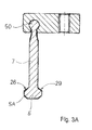
- this unit which is journalled to be pivotable on a pivot shaft 19, is made with a fixed length, and, for instance, the clapper 7 may alternatively be journalled by a ball-and-socket joint 50, as is shown in Fig. 3A .
- an appurtenant supporting part 20 for the locking part 5 varies in length.
- said part is formed of two portions 20A, 20B at least one of which may be replaced by one having a fitting length so that the length of stroke becomes the correct one.
- the holding together of the strip-shaped locking part 5 with said support part portions 20A, 20B is provided by bolts 21 and with the inner support part portion 20B being pivotably mounted via a pivot shaft 19 in a transverse part 22 which, via bolts 23, is attached to a mould half 24.
- Said recess 6 and end part 5A of the movable locking part 5 are shape-adapted to each other and have leaning co-operating sliding surfaces 25, 26, which co-operate with each other when the mould halves 24; 27 are displaced in the tool 2 in the direction of the arrow 28.
- the locking part 5, which is journalled to be pivotable, has a wedge-shaped actuation surface 29, which is turned directed inward toward the interior of the mould and an actuation part 30 connected with a mould half 27 has a pressure surface 31, which is arranged to be co-operatable with said actuation surface 29 of the locking part 5.
- the locking part is formed of a pivotably mounted hook-shaped arm 35, which has a leaning upright 36, which projects from the arm inward toward the interior of the mould and is receivable in a shape-adapted recess 37 of a mould half 27 in a reception part 53 attached thereto, and the function of said projecting upright 36 will be explained later.
- Said hook-shaped arm 35 is journalled to, with a hook part 47, be pivotable on a shaft 19 to be turned into engagement around an end part 40 of an arm 41, which is attached to a plate 11 externally on the moulding tool 2. Pivoting actuation of said arm 35 is provided by said leaning upright 36 receivable in the recess 37 and projecting from the arm 35.
- the length L of said hook-shaped pivotable and spring force-actuatable lock arm 35 determines the length of stroke of the movable plates of the tool.
- the lock arm 35 is guided in a recess 42 inside a bolted outer part 44, and between the fixed arm 41 and the outer part 44, tongue and groove 45, 46 are arranged.
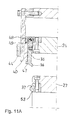
- a spring 39 which is received in a recess 37 in said arm 35, is arranged to, by its spring force, keep the swinging arm 35 in place in locked state, as is shown in Fig. 11A .
- actuation of the tool 2 entails that the mould halves 24, 27 are displaced together, the movable locking part 5 being turned in with the shape-adapted portion thereof in the appurtenant fitting recess 6, after pressing with the front the pressure surface 31 of the actuation part 30 against the movable locking part 5 and the wedge-shaped actuation surface 29 thereof.
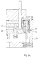
- the rear mould half 24 is retained in fixed position, and the front mould half 27 is then free to alone be displaced in the direction 28 from the rear mould half 24 until stop shoulders 51 situated in the front reaches the end half 12 and fitting recess 52 therein. See Fig. 1A .
- the movement of the mould halves 24, 27 in the direction of motion 28 is finished.
- the mould plates 24, 27 are brought along when the mould 4 opens.
- said lock arm 35 When the lock arm 35 has passed the end part 40 of the arm 41, said lock arm can be pressed out by the projecting leaning upright 36, so that a hook-shaped part 47 of the lock arm 35 assumes a position behind said arm end part 40, as is shown in Fig. 11A .
- a stopper 48 comes to stop with a shelf 49 of said arm 41 and stops the continued projection of the mould half 24. After that, the front mould half 27 is free to continue its projecting movement as shown in Fig.
Landscapes
- Engineering & Computer Science (AREA)
- Mechanical Engineering (AREA)
- Manufacturing & Machinery (AREA)
- Moulds For Moulding Plastics Or The Like (AREA)
Applications Claiming Priority (1)
| Application Number | Priority Date | Filing Date | Title |
|---|---|---|---|
| SE1351105A SE1351105A1 (sv) | 2013-09-25 | 2013-09-25 | Anordning vid formningsverktyg |
Publications (1)
| Publication Number | Publication Date |
|---|---|
| EP2853373A1 true EP2853373A1 (fr) | 2015-04-01 |
Family
ID=51659476
Family Applications (1)
| Application Number | Title | Priority Date | Filing Date |
|---|---|---|---|
| EP14184914.1A Withdrawn EP2853373A1 (fr) | 2013-09-25 | 2014-09-16 | Dispositif dans un outil de moulage |
Country Status (2)
| Country | Link |
|---|---|
| EP (1) | EP2853373A1 (fr) |
| SE (1) | SE1351105A1 (fr) |
Citations (12)
| Publication number | Priority date | Publication date | Assignee | Title |
|---|---|---|---|---|
| US3004291A (en) | 1958-01-14 | 1961-10-17 | Eric Dent | Apparatus for forming brushes |
| GB1329550A (en) | 1970-09-18 | 1973-09-12 | Olivetti & Co Spa | Plastics moulding presses |
| JPS5171354A (ja) | 1974-12-18 | 1976-06-21 | Hitachi Ltd | Shashutsuseikeiyokanagata |
| FR2337618A1 (fr) | 1976-01-09 | 1977-08-05 | Olivetti & Co Spa | Perfectionnement a une presse a injection pour moulage de matieres plastiques et similaires |
| US4239174A (en) * | 1978-11-14 | 1980-12-16 | Mueller Hans | Two step ejector structure for a mold for injection molding or the like |
| DE3103718A1 (de) * | 1979-08-31 | 1982-09-23 | Franz 7743 Furtwangen Ketterer | Kupplung zur loesbaren verbindung von formplatten einer spritzgiess- oder pressform |
| JPS5850822U (ja) * | 1981-09-28 | 1983-04-06 | 河西工業株式会社 | 射出成形金型 |
| JPS5878735A (ja) * | 1981-11-05 | 1983-05-12 | Kojima Press Co Ltd | アンダ−カツト部を有する製品の成形装置 |
| JPS6213616U (fr) * | 1985-07-09 | 1987-01-27 | ||
| JPH0516257U (ja) * | 1991-08-09 | 1993-03-02 | マツダ株式会社 | 射出成形用金型 |
| JPH0650830U (ja) * | 1992-12-22 | 1994-07-12 | イカワテクノロジー株式会社 | 射出成形金型における二段突き出し装置 |
| JP2000202882A (ja) | 1999-01-14 | 2000-07-25 | Arisaka Kanagata Seisakusho:Kk | 金型用作動制御装置 |
-
2013
- 2013-09-25 SE SE1351105A patent/SE1351105A1/sv not_active Application Discontinuation
-
2014
- 2014-09-16 EP EP14184914.1A patent/EP2853373A1/fr not_active Withdrawn
Patent Citations (12)
| Publication number | Priority date | Publication date | Assignee | Title |
|---|---|---|---|---|
| US3004291A (en) | 1958-01-14 | 1961-10-17 | Eric Dent | Apparatus for forming brushes |
| GB1329550A (en) | 1970-09-18 | 1973-09-12 | Olivetti & Co Spa | Plastics moulding presses |
| JPS5171354A (ja) | 1974-12-18 | 1976-06-21 | Hitachi Ltd | Shashutsuseikeiyokanagata |
| FR2337618A1 (fr) | 1976-01-09 | 1977-08-05 | Olivetti & Co Spa | Perfectionnement a une presse a injection pour moulage de matieres plastiques et similaires |
| US4239174A (en) * | 1978-11-14 | 1980-12-16 | Mueller Hans | Two step ejector structure for a mold for injection molding or the like |
| DE3103718A1 (de) * | 1979-08-31 | 1982-09-23 | Franz 7743 Furtwangen Ketterer | Kupplung zur loesbaren verbindung von formplatten einer spritzgiess- oder pressform |
| JPS5850822U (ja) * | 1981-09-28 | 1983-04-06 | 河西工業株式会社 | 射出成形金型 |
| JPS5878735A (ja) * | 1981-11-05 | 1983-05-12 | Kojima Press Co Ltd | アンダ−カツト部を有する製品の成形装置 |
| JPS6213616U (fr) * | 1985-07-09 | 1987-01-27 | ||
| JPH0516257U (ja) * | 1991-08-09 | 1993-03-02 | マツダ株式会社 | 射出成形用金型 |
| JPH0650830U (ja) * | 1992-12-22 | 1994-07-12 | イカワテクノロジー株式会社 | 射出成形金型における二段突き出し装置 |
| JP2000202882A (ja) | 1999-01-14 | 2000-07-25 | Arisaka Kanagata Seisakusho:Kk | 金型用作動制御装置 |
Non-Patent Citations (1)
| Title |
|---|
| "DIE HOHE SCHULE DES AUSWERFENS", PLASTVERARBEITER, HUETHIG GMBH, HEIDELBERG, DE, vol. 48, no. 4, 1 April 1997 (1997-04-01), pages 64,66, XP000656303, ISSN: 0032-1338 * |
Also Published As
| Publication number | Publication date |
|---|---|
| SE1351105A1 (sv) | 2015-03-26 |
Similar Documents
| Publication | Publication Date | Title |
|---|---|---|
| EP1900880A3 (fr) | Dispositif pour raccorder un outil à un moyen de commande d'une machine de travail | |
| EP1327502A3 (fr) | Poignée transversale pliante pour outil long | |
| EP1903137A3 (fr) | Machine à laver | |
| EP2865814A3 (fr) | Ensemble d'usure destiné à un équipement d'excavation | |
| JP2014046452A (ja) | 切削インサート用ホルダ組立体及び切削工具 | |
| JP2017070734A (ja) | スライドレールキット用の取付部材 | |
| EP1825941A3 (fr) | Serre-barre pour avance-barre | |
| JP5847093B2 (ja) | モップヘッドと絞り装置の組み合わせ | |
| EP2853373A1 (fr) | Dispositif dans un outil de moulage | |
| KR20100062605A (ko) | 샤시 코너 클랩핑 장치 | |
| US8782908B2 (en) | Stud punch tool | |
| US7140868B1 (en) | Universal lifter foot assembly for removal of core block from mold | |
| WO2017131508A1 (fr) | Mécanisme de blocage de support de conformateur | |
| CN204685938U (zh) | 二模三冲螺丝机用顶出装置 | |
| EP2450021A3 (fr) | Mécanisme de pince | |
| EP3165682A3 (fr) | Attache rapide | |
| CN201883822U (zh) | 一种可调式锁扣 | |
| CN205798232U (zh) | 锁闩筒与连接片自动铆合装置 | |
| CN109821981A (zh) | 模具 | |
| EP1970311A3 (fr) | Tête de soudure pour machines de cerclage | |
| CN205764200U (zh) | 一种曲线锯装刀装置 | |
| CN204058771U (zh) | 用于钩接的装置以及使用该装置的织机 | |
| CN203738150U (zh) | 一种折叠式多用途手锯 | |
| CN210817054U (zh) | 一种耐磨的加工模具 | |
| CN103104578B (zh) | 一种夹具 |
Legal Events
| Date | Code | Title | Description |
|---|---|---|---|
| PUAI | Public reference made under article 153(3) epc to a published international application that has entered the european phase |
Free format text: ORIGINAL CODE: 0009012 |
|
| 17P | Request for examination filed |
Effective date: 20140916 |
|
| AK | Designated contracting states |
Kind code of ref document: A1 Designated state(s): AL AT BE BG CH CY CZ DE DK EE ES FI FR GB GR HR HU IE IS IT LI LT LU LV MC MK MT NL NO PL PT RO RS SE SI SK SM TR |
|
| AX | Request for extension of the european patent |
Extension state: BA ME |
|
| STAA | Information on the status of an ep patent application or granted ep patent |
Free format text: STATUS: THE APPLICATION HAS BEEN WITHDRAWN |
|
| 18W | Application withdrawn |
Effective date: 20150612 |