EP2853382B1 - Système de superposition de couches de tissu automatisé et procédé - Google Patents
Système de superposition de couches de tissu automatisé et procédé Download PDFInfo
- Publication number
- EP2853382B1 EP2853382B1 EP14192529.7A EP14192529A EP2853382B1 EP 2853382 B1 EP2853382 B1 EP 2853382B1 EP 14192529 A EP14192529 A EP 14192529A EP 2853382 B1 EP2853382 B1 EP 2853382B1
- Authority
- EP
- European Patent Office
- Prior art keywords
- location
- layup form
- edge
- response
- layup
- Prior art date
- Legal status (The legal status is an assumption and is not a legal conclusion. Google has not performed a legal analysis and makes no representation as to the accuracy of the status listed.)
- Expired - Lifetime
Links
Images




Classifications
-
- B—PERFORMING OPERATIONS; TRANSPORTING
- B29—WORKING OF PLASTICS; WORKING OF SUBSTANCES IN A PLASTIC STATE IN GENERAL
- B29C—SHAPING OR JOINING OF PLASTICS; SHAPING OF MATERIAL IN A PLASTIC STATE, NOT OTHERWISE PROVIDED FOR; AFTER-TREATMENT OF THE SHAPED PRODUCTS, e.g. REPAIRING
- B29C70/00—Shaping composites, i.e. plastics material comprising reinforcements, fillers or preformed parts, e.g. inserts
- B29C70/04—Shaping composites, i.e. plastics material comprising reinforcements, fillers or preformed parts, e.g. inserts comprising reinforcements only, e.g. self-reinforcing plastics
- B29C70/28—Shaping operations therefor
- B29C70/54—Component parts, details or accessories; Auxiliary operations, e.g. feeding or storage of prepregs or SMC after impregnation or during ageing
- B29C70/545—Perforating, cutting or machining during or after moulding
-
- B—PERFORMING OPERATIONS; TRANSPORTING
- B29—WORKING OF PLASTICS; WORKING OF SUBSTANCES IN A PLASTIC STATE IN GENERAL
- B29C—SHAPING OR JOINING OF PLASTICS; SHAPING OF MATERIAL IN A PLASTIC STATE, NOT OTHERWISE PROVIDED FOR; AFTER-TREATMENT OF THE SHAPED PRODUCTS, e.g. REPAIRING
- B29C70/00—Shaping composites, i.e. plastics material comprising reinforcements, fillers or preformed parts, e.g. inserts
- B29C70/04—Shaping composites, i.e. plastics material comprising reinforcements, fillers or preformed parts, e.g. inserts comprising reinforcements only, e.g. self-reinforcing plastics
- B29C70/28—Shaping operations therefor
- B29C70/30—Shaping by lay-up, i.e. applying fibres, tape or broadsheet on a mould, former or core; Shaping by spray-up, i.e. spraying of fibres on a mould, former or core
- B29C70/38—Automated lay-up, e.g. using robots, laying filaments according to predetermined patterns
- B29C70/386—Automated tape laying [ATL]
-
- Y—GENERAL TAGGING OF NEW TECHNOLOGICAL DEVELOPMENTS; GENERAL TAGGING OF CROSS-SECTIONAL TECHNOLOGIES SPANNING OVER SEVERAL SECTIONS OF THE IPC; TECHNICAL SUBJECTS COVERED BY FORMER USPC CROSS-REFERENCE ART COLLECTIONS [XRACs] AND DIGESTS
- Y10—TECHNICAL SUBJECTS COVERED BY FORMER USPC
- Y10T—TECHNICAL SUBJECTS COVERED BY FORMER US CLASSIFICATION
- Y10T156/00—Adhesive bonding and miscellaneous chemical manufacture
- Y10T156/10—Methods of surface bonding and/or assembly therefor
- Y10T156/1052—Methods of surface bonding and/or assembly therefor with cutting, punching, tearing or severing
- Y10T156/1062—Prior to assembly
- Y10T156/1075—Prior to assembly of plural laminae from single stock and assembling to each other or to additional lamina
- Y10T156/1077—Applying plural cut laminae to single face of additional lamina
-
- Y—GENERAL TAGGING OF NEW TECHNOLOGICAL DEVELOPMENTS; GENERAL TAGGING OF CROSS-SECTIONAL TECHNOLOGIES SPANNING OVER SEVERAL SECTIONS OF THE IPC; TECHNICAL SUBJECTS COVERED BY FORMER USPC CROSS-REFERENCE ART COLLECTIONS [XRACs] AND DIGESTS
- Y10—TECHNICAL SUBJECTS COVERED BY FORMER USPC
- Y10T—TECHNICAL SUBJECTS COVERED BY FORMER US CLASSIFICATION
- Y10T156/00—Adhesive bonding and miscellaneous chemical manufacture
- Y10T156/12—Surface bonding means and/or assembly means with cutting, punching, piercing, severing or tearing
- Y10T156/1348—Work traversing type
- Y10T156/1365—Fixed cutter
-
- Y—GENERAL TAGGING OF NEW TECHNOLOGICAL DEVELOPMENTS; GENERAL TAGGING OF CROSS-SECTIONAL TECHNOLOGIES SPANNING OVER SEVERAL SECTIONS OF THE IPC; TECHNICAL SUBJECTS COVERED BY FORMER USPC CROSS-REFERENCE ART COLLECTIONS [XRACs] AND DIGESTS
- Y10—TECHNICAL SUBJECTS COVERED BY FORMER USPC
- Y10T—TECHNICAL SUBJECTS COVERED BY FORMER US CLASSIFICATION
- Y10T156/00—Adhesive bonding and miscellaneous chemical manufacture
- Y10T156/12—Surface bonding means and/or assembly means with cutting, punching, piercing, severing or tearing
- Y10T156/1374—Surface bonding means and/or assembly means with cutting, punching, piercing, severing or tearing with means projecting fluid against work
-
- Y—GENERAL TAGGING OF NEW TECHNOLOGICAL DEVELOPMENTS; GENERAL TAGGING OF CROSS-SECTIONAL TECHNOLOGIES SPANNING OVER SEVERAL SECTIONS OF THE IPC; TECHNICAL SUBJECTS COVERED BY FORMER USPC CROSS-REFERENCE ART COLLECTIONS [XRACs] AND DIGESTS
- Y10—TECHNICAL SUBJECTS COVERED BY FORMER USPC
- Y10T—TECHNICAL SUBJECTS COVERED BY FORMER US CLASSIFICATION
- Y10T156/00—Adhesive bonding and miscellaneous chemical manufacture
- Y10T156/17—Surface bonding means and/or assemblymeans with work feeding or handling means
- Y10T156/1788—Work traversing type and/or means applying work to wall or static structure
- Y10T156/1795—Implement carried web supply
Definitions
- the present invention generally relates to a device, system and method of fabricating a composite item. More particularly, the present invention pertains to an automated fabric layup device and system and a method of use.
- Composite structures are typically constructed from multiple layers or plies.
- the plies are generally made up of a series of courses that slightly overlap or abut one another. These courses may include a variety of materials such as glass, aramid, and carbon fiber, various other fibers, and the like. In addition, the fibers may be oriented in a single direction or woven into a fabric.
- the course material may further be pre-impregnated with a resin and are often dispensed from a roll. In roll form, the course material typically includes a separator film or backing film of plastic, paper, or the like. This backing film generally prevents resin coated or pre-impregnated course material (prepreg) from adhering to itself.
- the courses are generally laid upon the form or tool along a "natural path" of the course material.
- the term "natural path” refers to the path the course material would follow when rolled out on to the surface of the tool. Deviations from the natural path are generally achieved by applying force across the width of the course material. When the force applied exceeds the flexing capacity of the material, wrinkles or bridges form in the course material. In addition, the wider the course is, the more prone the course material is to wrinkle. However, in general, it is advantageous to utilize relatively wide course material so as to increase layup rates.
- Conventional methods of constructing contoured composite structures from fabric course material employ skilled technicians to hand lay the fabric. These technicians pull on the edges and corners of the fabric to deform or trellis the weave of the fabric. In this manner, the fabric is induced to conform to the contour.
- EP1422048A2 in accordance with its abstract, states a device for fabricating a composite article having a plurality of material dispensers to increase productivity.
- the device includes a structure defining a work surface datum, the plurality of material dispensers which are movable relative to the structure, where each of the material dispensers applies a strip material to the work surface datum along a predetermined axis, and wherein each of said predetermined axes are parallel to one another and where the strip material as applied to the work surface datum forms a layer.
- an apparatus for fabricating a composite item from a material placed on a layup form having large contours of up to about 50.8 cm (20 inches) positive radius comprising: means for determining a first location on the layup form to place the material; means for determining a second location on the layup form to stop placing the material; means for cutting the material to generate a first edge that substantially conforms to the layup form at the first location in response to the first edge being different from the layup form at the first location; means for tacking the first edge to the layup form at the first location; means for applying the material along a natural path of the layup form between the first location and the second location, wherein the material is urged outward from about a longitudinal centerline of the material by movement of a curved surface relative to the material; means for cutting the material to generate a second edge that substantially conforms to the layup form at the second location in response to approaching the second location; and means for applying a tackifier to the layup form in an area defined by the material being placed
- a method of fabricating a composite item from a material placed on a layup form having large contours of up to about 50 cm positive radius comprising: determining a first location on the layup form to place the material; determining a second location on the layup form to stop placing the material; cutting the material to generate a first edge that substantially conforms to the layup form at the first location in response to the first edge being different from the layup form at the first location; tacking the first edge to the layup form at the first location; applying the material along a natural path of the layup form between the first location and the second location, wherein the material is urged outward from about a longitudinal centerline of the material by movement of a curved surface relative to the material; cutting the material to generate a second edge that substantially conforms to the layup form at the second location in response to approaching the second location; and applying a tackifier to the layup form in an area defined by the material being placed on the layup form substantially without applying the tackifier outside the area
- An embodiment relates to a device to apply a resin impregnated fabric to a substrate.
- the device includes a surface having a layer of material and a first edge. The surface moves relative to the substrate and to conform to the substrate.
- the layer of material is compatible for use with the resin.
- the first edge is disposed at the front of the surface relative to the movement of the device to the fabric.
- the first edge is curved with a center portion of the first edge being relatively forward of a pair of side portions of the first edge.
- the device includes a supply reel, a cutting system, and a pressure shoe.
- the supply reel supplies the resin impregnated fabric.
- the cutting system cuts resin impregnated fabric.
- the pressure shoe presses the resin impregnated fabric on to the substrate.
- the pressure shoe includes a surface having a layer and a first edge. The surface moves relative to the substrate and to conform to the substrate. The layer of material is compatible for use with the resin.
- the first edge is disposed at the front of the surface relative to the movement of the pressure shoe to the fabric.
- the first edge is curved with a center portion of the first edge being relatively forward of a pair of side portions of the first edge.
- Yet another embodiment relates to a system for fabricating a composite item from a resin impregnated fabric placed on a layup form.
- the system includes a fabric lamination machine that includes an end effector.
- the fabric lamination machine moves the end effector along a natural path across the layup form.
- the end effector includes a supply reel and a pressure shoe.
- the supply reel retains a supply of the resin impregnated fabric.
- the resin impregnated fabric is withdrawn from the supply reel at a feed rate.
- the pressure shoe presses the resin impregnated fabric on to the layup form.
- the pressure shoe includes a surface having a layer of material and a first edge. The surface moves relative to the layup form and conforms to the layup form.
- the layer of material is compatible for use with the resin.
- the first edge is disposed at the front of the surface relative to the movement of the pressure shoe to the resin impregnated fabric.
- the first edge is curved with a center portion of the first edge
- Yet another embodiment pertains to an apparatus for fabricating a composite item from a material placed on a layup form.
- the apparatus includes a means for determining a first location on the layup form to place the material, a means for determining a second location on the layup form to stop placing the material, and a means for cutting the material to generate a first edge that substantially conforms to the layup form at the first location in response to the first edge being different from the layup form at the first location.
- the apparatus includes a means for tacking the first edge to the layup form at the first location and a means for applying the material along a natural path of the layup form between the first location and the second location.
- the material is urged outward from about a longitudinal centerline of the material by movement of a curved surface relative to the material.
- the apparatus further includes a means for cutting the material to generate a second edge that substantially conforms to the layup form at the second location in response to approaching the second location.
- Yet another embodiment relates to a method of fabricating a composite item from a material placed on a layup form.
- a first location is determined on the layup form to place the material
- a second location is determined on the layup form to stop placing the material
- the material is cut to generate a first edge that substantially conforms to the layup form at the first location in response to the first edge being different from the layup form at the first location.
- the first edge is tacked to the layup form at the first location
- the material is applied along a natural path of the layup form between the first location and the second location.
- the material is urged outward from about a longitudinal centerline of the material by movement of a curved surface relative to the material and the material is cut to generate a second edge that substantially conforms to the layup form at the second location in response to approaching the second location.
- Yet another embodiment pertains to a computer readable medium on which is embedded computer software comprising a set of instructions for executing a method of fabricating a composite item from a material placed on a layup form.
- a first location is determined on the layup form to place the material
- a second location is determined on the layup form to stop placing the material
- the material is cut to generate a first edge that substantially conforms to the layup form at the first location in response to the first edge being different from the layup form at the first location.
- the first edge is tacked to the layup form at the first location
- the material is applied along a natural path of the layup form between the first location and the second location.
- the material is urged outward from about a longitudinal centerline of the material by movement of a curved surface relative to the material and the material is cut to generate a second edge that substantially conforms to the layup form at the second location in response to approaching the second location.
- the present invention provides, in some embodiments, a system for placing plies to generate a composite item and a method of using this system.
- the invention provides for a numerically controlled (NC) automated fabric lamination machine (AFLM).
- NC numerically controlled
- AFLM automated fabric lamination machine
- This lamination device includes a positioning device to position an end effector.
- the positioning device includes any suitable device such as a gantry, robotic armature, wheeled or tracked vehicle, and/or the like.
- the end effector generally includes any device suitable to be positioned by the positioning device.
- end effectors include milling, dispensing, and/or finishing heads or modules.
- the end effector includes a dispensing head to place plies, or resin impregnated fabric, upon a layup mold or tool.
- the ply material is slightly tacky and will adhere to the surface of the tool, or previously applied plies, in response to a sufficient amount of compressive force.
- the end effector includes a pressure shoe module.
- the end effector includes a cutting assembly having a rotating anvil to support cuts in the ply material.
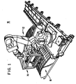
- FIG. 1 is a perspective view of an automated fabric lamination machine (AFLM) 10 suitable for use with an embodiment of the invention.
- the AFLM 10 includes a positioning device 12 to control the movement of an end effector 14 relative to a layup mold or tool 16.
- the positioning device 12 includes any suitable system to control the movement of the end effector 14 relative to the tool 16. Examples of suitable systems include an armature type device as illustrated in FIG. 1 , a gantry type device, and the like.
- the positioning device 12 is configured to control twelve axes of movement (seven axes of the positioning device and five axes of the end effector 14).
- twelve axes of movement may depend upon the particular operating condition and thus, the number of axes controlled is not critical to the invention.
- FIGS. 2 and 3 are perspective views of the end effector 14.
- a pre-impregnated fabric material (“prepreg") 18 is stored on a supply roll 20.
- a separator or backing film 22 is stripped away and accumulates on a backing take-up roll 24.
- the prepreg 18 is conveyed to and wrapped partially around a vacuum cutting drum 26 or anvil.
- This cutting drum 26 includes a porous tube 28 of a material suitable for use as a knife cutting back-up surface. Examples of suitable materials include ultra high molecular weight (“UHMW”) polyethylene, Delrin®, nylon, acetal, and the like.
- UHMW ultra high molecular weight
- a vacuum chamber 30 is disposed within the drum 26 and configured to draw air through the porous tube 28. In this manner, the prepreg 18 is drawn toward the cutting drum 26 and essentially held in place along the outside of the tube 28. In an embodiment, air is drawn through the cutting drum 26 at those locations covered by the prepreg 18 and is essentially sealed at those locations not covered by the prepreg 18. In this manner, vacuum pressure is not wasted.
- the vacuum chamber 30 includes a seal S that directs the vacuum towards about half of the circumference of the cutting drum 26.
- the end effector 14 further includes one or more cutting assemblies 32 to cut the prepreg 18.
- the end effector 14 includes a pair of cutting assemblies 32 configured to cut the prepreg 18 held on the drum 26.
- the cutting assemblies 32 perform end cuts, such as leading edge and trailing edge cuts and/or perform cuts to generate side edge profiles.
- the cutting assemblies 32 include any suitable device operable to sever or otherwise cut the prepreg 18. Suitable devices include ultrasonic knives, saws, lasers, and the like.
- the cutting assemblies 32 are configured to perform according to signals from a controlling device. In this regard, to generate edge profiles and diagonal cuts in the prepreg 18, movement of the cutting drum 26 is controlled to coincide with movement of the cutting assemblies 32.
- movement of the cutting drum 26 is utilized to orchestrate movements of the various other components of the AFLM 10.
- the supply roll 20 is controlled to dispense prepreg 18 and the positioning device 12 is controlled to advance the end effector 14 along the tool 16.
- the cutting assemblies 32 are offset with regard to their respective positions along the cutting drum 26. In this manner, each of the cutting assemblies 32 are configured to cut across the full width of the prepreg 18 or any portion thereof without interfering with the action of the one or more other cutting assembly 32. It is an advantage of the offset in the cutting assemblies 32 that while one cutting assembly 32 is cutting a profile of the prepreg 18, another cutting assembly 32 may perform an end cut.
- the end effector 14 further includes a pressure shoe 34 and pressure shoe module 36.
- the pressure shoe module 36 is configured to transfer the prepreg 18 from the drum 26 and apply the material on to the tool 16. For example, in response to a leading edge of the prepreg 18 reaching an appropriate position along the drum 26, the prepreg 18 is detachably secured to the pressure shoe 34.
- the pressure shoe module 36 is configured to control the movement of the pressure shoe 34 from a 'transfer' position shown in FIG. 2 to a 'laydown' position shown in FIG. 3 . As the pressure shoe 34 is moved in this manner, additional prepreg 18 is fed and processed through the end effector 14 to provide sufficient slack and form a "loop" of the prepreg 18 ahead of the pressure shoe 34.
- prepreg 18 beyond the edge profile cut by the cutting assemblies 32 is accumulated on a take-up roll 38. In an embodiment, some portion of each side edge of the prepreg 18 is left uncut. In this manner, a continuous strip of prepreg 18 is generated that facilitates collection of the prepreg 18.
- the pressure shoe module 36 includes a plurality of linkages 40. These linkages 40 are configured to facilitate movement of the pressure shoe 34 along the paths 42 indicated by the dashed lines shown in FIG. 3 .
- various other components of the AFLM 10 are synchronized during transfer. That is the prepreg 18 being dispensed by the vacuum cutting drum 26 and the edges profiled by the cutting assemblies 32 are controlled in such a manner so as to maintain the positional integrity of the prepreg 18 relative to the pressure shoe 34. In other words, sufficient prepreg 18 is dispensed during the transfer that tension does not build up and cause the prepreg 18 to slide on the pressure shoe 34. In this manner, the cut edges may be accurately placed upon the tool 16.
- the pressure shoe 34 initially moves away from the drum 26 in an essentially tangent manner. That is, relatively little torque is initially applied to the prepreg 18.
- the pressure shoe module 36 is controlled to orient the pressure shoe 34 and attached prepreg 18 into the laydown position as illustrated in FIG. 3 .
- the pressure shoe module 36 is controlled to move in a similar manner utilizing other suitable devices.
- the pressure shoe module 36 is configured to follow a race or other such channel that conforms to the path 42.
- a numerically controlled armature is configured to control the pressure shoe module 36 along the path 42.
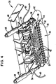
- FIG. 4 is a perspective view of the pressure shoe 34 and pressure shoe module 36 according to an embodiment shown in FIG. 1 .
- the pressure shoe 34 includes a contact surface 44, conforming material 46, and vacuum ports 48.
- the contact surface 44 includes a flexible material suitable for use with the resin impregnated prepreg 18. Examples of suitable materials include polyethylene polymers, UHMW polyethylene, Delrin®, nylon, acetal, and the like.
- the contact surface 44 includes a curved forward edge 50. It is an advantage of embodiments of the invention that the curved forward edge 50 facilitates an outward spreading of the prepreg 18 as the prepreg 18 is being applied to the tool 16.
- the conforming material 46 includes a foam or other such compressible and resilient material that provides support for the contact surface 44 and facilitates conformation of the contact surface 44 to a contour of the tool 16. More particularly, the conforming material 46 facilitates conformation to positive and negative radius contours that are in line with the contact surface 44, perpendicular to the contact surface 44, and/or at an oblique angle to the contact surface 44.
- the amount of curvature the conforming material 46 is able to accommodate is dependent upon a variety of factors, such as, for example: length, width, thickness, compressibility, and resilience of the conforming material 46.
- the vacuum ports 48 are disposed in close proximity to a trailing edge 52 of the contact surface 44.
- the vacuum ports 48 are in fluid connection to a vacuum source such as, for example a vacuum pump, vacuum producing venturi, and/or the like.
- a vacuum source such as, for example a vacuum pump, vacuum producing venturi, and/or the like.
- each vacuum port 48 is connected to a respective vacuum hose 54, which in turn, is connected to a vacuum manifold 56.
- the vacuum manifold 56 is in fluid connection to a vacuum producing venturi 58 that is powered via a pressure hose 60 that supplies compressed air.
- the vacuum hoses 54 are routed to vacuum ports 48 as illustrated in FIG. 4 .
- the vacuum ports 48 are disposed about the middle and/or curved forward edge 50 of the contact surface 44.
- the vacuum ports 48 are illustrated in FIG. 4 as being substantially uniform in size and spaced substantially evenly along the trailing edge 52, in other embodiments, the spacing and/or port diameter is heterogeneous.
- the vacuum ports 48 are disposed more densely towards the center of the contact surface 44.
- the vacuum ports 48 need not be holes, but rather, include porous or permeable material.
- the pressure shoe module 36 includes a spring 62, actuator 64, and attachment flanges 66.
- the spring 62 or platen, supports the contact surface 44 and is configured to conform to a contour in the tool 16.
- the conforming material 46 facilitates conformation to relatively small contours in the tool while the spring 62 facilitates conformation to relatively large contours in the tool.
- the spring 62 includes a sheet of resilient material such as metals, plastics, composites, and/or the like.
- the spring 62 includes a sheet of fiberglass that, as shown in FIG. 4 , is supported at both ends and configured to flex.
- the cross-section of the spring 62 is varied across the length.
- the amount of curvature the spring 62 is able to accommodate is dependent upon a variety of factors, such as, for example: length, width, thickness, and resilience of the spring 62.
- the spring 62 is configured to facilitate conformation to contours having a positive radius of about 20 inches or greater.
- the actuator 64 applies torque to the linkages 40 in response to controlling signals. In this manner, the pressure shoe module 36 is moved between the transfer and laydown positions.
- the attachment flanges 66 provide fastening points to attach the pressure shoe module 36 to the end effector 14.
- the pressure shoe module 36 optionally includes a respective exhaust muffler 68 for each of the vacuum producing venturis 58 to lessen noise produced therein.
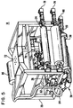
- FIG. 5 is a perspective view of the end effector 14 according to an embodiment shown in FIG. 1 .
- end effector 14 includes a housing or frame 70 to attach and support the various components of the end effector 14.
- the frame 70 includes a mounting plate 72 to secure the end effector 14 to the positioning device 12.
- a plurality of actuators 74-80 configured to respectively control the rotational movement of the supply roll 20, backing take-up roll 24, vacuum cutting drum 26, and take-up roll 38.
- a hub 82, vacuum hose 84, and vacuum producing device 86 such as a vacuum pump, turbine, and/or venturi/muffler.
- FIG. 6 is a block diagram of a system 90 suitable for use with the AFLM 10.
- the system 90 includes a controller 92.
- the controller 92 is operable to execute computer readable code.
- the system 90 includes a set of computer readable instructions or code 94.
- the controller 92 is configured to access a file 96.
- This file 96 includes one or more of the following: a computer readable model of the composite item; a computer readable representation of the surface of the layup form or the tool 16; a computer readable representation of the edges of the tool 16; the thickness of the composite item; a source code based upon at least one of the composite item and the tool 16; a set of movement instructions based upon the source code; data gathered while laying up the composite item; timestamp information; positional information; identification numbers; and the like.
- the controller 92 is further configured to communicate across a network 98.
- the network 98 is optionally included to provide additional data storage and/or processing capabilities.
- the network includes a database 100 and a server 102.
- the database 100 is configured to store a copy of the code 94 and/or file 96.
- the server 102 is configured to generate, store, and perform any suitable processing of the code 94 and/or file 96. In this manner, composite items generated on computer aided design (CAD) machines such as the server 102, for example, may be forwarded to the AFLM 10.
- CAD computer aided design
- the server 102 is operable, via the network 98, to forward updates for the code 94 and/or file 94.
- the system 90 optionally includes a memory 104. If present, the memory 104 is configured to store a copy of the code 94 and/or file 96.
- the positioning device controller 106 is optionally included in the system 90 depending upon the requirements of the various actuators and/or servo motors of the AFLM 10. That is, depending upon the particular configuration of the AFLM 10, a plurality of actuators and/or servo motors modulate the rotation, position, speed, direction, and the like of the various components of the AFLM 10. More particularly, these actuators and/or servo motors of the positioning device are at least configured to modulate the various axes of the end effector 14 and/or AFLM 10. If present, parameters of the positioning device controller 106 are based upon the specification of the various actuators, servos, and/or the controller 92.
- the positioning device controller 106 if present, is configured to control some or all of these actuators and/or servo motors. In addition, these actuators and/or servo motors are optionally operable to be modulated by the controller 92 directly, and thus, the system 90 may not include the positioning device controller 106.
- the controller 92 is configured to modulate any suitable actuator and/or servo motor, such as the actuators 64 and 74-80 and the cutting assemblies 32 for example, and thereby control the various components of the AFLM 10. In this manner, the controller 92 is configured to control the movement of the prepreg 18 through the end effector 14.
- the actuators 74-80 are configured to modulate the position, speed, direction, tension, and the like of the prepreg 18 and the separator film.
- the controller 92 is configured to modulate the actuator 64 and thereby control the pressure shoe module 36.
- the system 90 further includes a plurality of sensors configured to sense the various operating conditions of the AFLM 10. More particularly, the system 90 optionally includes sensors to sense any suitable attribute of the AFLM 10. Examples of suitable attributes include some or all of the temperature of the prepreg 18, the temperature at the location where the separator film 22 is separated from the prepreg 18 (release point), feed rate and direction, material placement, backing integrity, supply of prepreg 18, prepreg 18 tension between the supply roll 20 and the vacuum cutting drum 26, prepreg 18 tension between the vacuum cutting drum 26 and take-up roll 38, and/or the like.
- the system 90 optionally includes a tackifier applicator 108.
- the tackifier facilitates first ply adhesion to the tool 16.
- tackifier resins modify the rheological properties of an adhesive system. These tackifiers are combined with base polymers/elastomers in adhesives to improve the tack or ability to stick. In general this property is achieved by an increased wetting out onto a surface and improved specific adhesion. More specifically, by modulating the tackifier and base resin combination, the viscoelastic behavior of the adhesive is varied. In addition, the particular tackifier utilized is typically dependent upon its suitability or compatibility with the base resin.
- suitable tackifiers for use with a bismaleimide (BMI) resin base may include: Toray E-09 manufactured by Toray Composites (America) of Tacoma, WA; MSR 355-HSC manufactured by The Boeing Company of Chicago, IL; and the like.
- the invention is not limited to the use of BMI resin and its compatible tackifiers, but rather, any suitable resin and base/tackifier resin system is within the scope of embodiments of the invention.
- tackifier may tend to foul the contact surface 44.
- the width of the prepreg 18 is modulated by the cutting assemblies 32, so to is the width of the tackifier application modulated.
- the tackifier applicator 108 applies the tackifier in a controllable manner.
- the tackifier applicator 108 is modulated by the controller 92 to apply the tackifier to the tool 16 in an area where the prepreg 18 is to be placed substantially without overlap into adjacent areas.
- the tackifier applicator 108 includes an array of independently controllable spray nozzles that essentially span the width of the prepreg 18.
- the tackifier applicator 108 includes a spray nozzle that is controllable to sweep to and fro and thereby span the width of the prepreg 18 or some portion thereof.
- the system 90 optionally includes a heater 110.
- the heater 110 includes any suitable heating device such as, for example an electrical heating element and blower, infrared device, induction heater, and/or the like.
- the heater 110 includes a heating element and a blower configured to direct a stream of heated air as appropriate.
- the stream of heated air may be directed aft of the tackifier applicator 108 and forward of the pressure shoe module 36.
- the heater 110 optionally includes a nib heater, chute heater, and release point blower. If present, these devices are modulated by the controller 92.
- the nib heater applies a controlled amount of heat to the tool 16, the prepreg 18 and/or the separator film 22 in response to controlling signals generated by the controller 92.
- the chute heater applies a controlled amount of heat to the prepreg 18 and/or the separator film 22 in response to controlling signals generated by the controller 92.
- the release point blower directs a flow of air toward the release point in response to controlling signals generated by the controller 92.
- FIG. 7 is a system architecture for the controller 92 suitable for use in the system 90.
- the controller 92 includes a processor 116.
- This processor 116 is operably connected to a power supply 118, memory 120, clock 122, analog to digital converter (A/D) 124, and an input/output (I/O) port 126.
- the I/O port 126 is configured to receive signals from any suitably attached electronic device and forward these signals to the A/D 124 and/or the processor 116. If the signals are in analog format, the signals may proceed via the A/D 124.
- the A/D 124 is configured to receive analog format signals and convert these signals into corresponding digital format signals.
- the A/D 124 is configured to receive digital format signals from the processor 116, convert these signals to analog format, and forward the analog signals to the I/O port 126.
- electronic devices configured to receive analog signals may intercommunicate with the processor 116.
- the processor 116 is configured to receive and transmit signals to and from the A/D 124 and/or the I/O port 126.
- the processor 116 is further configured to receive time signals from the clock 122.
- the processor 116 is configured to store and retrieve electronic data to and from the memory 120.
- the processor 116 is configured to determine signals operable to modulate the positioning device controller 106 and thereby control the various actuators and/or servo motors of the AFLM 10 to exert a particular force and/or rotate to a particular degree. For example, signals associated with rotating the actuator 78 in a clockwise direction may be forwarded to the actuator 78 by the processor 116 via the I/O port 126 and thereby control the prepreg 18 to advance.
- the processor 116 is configured to execute the code 94. Based on this set of instructions and signals from the various components of the AFLM 10, the processor 116 is configured to: determine a set of movement instructions; modulate the heater 110, tackifier applicator 108, cutting assemblies 32, and the like.
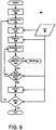
- FIG. 8 illustrates steps involved in a method 130 of placing plies to produce a composite structure or product.
- a composite product Prior to the initiation of the method 130, a composite product is designed and, based on this design, a series of computer readable instructions specifying attributes of the composite product is generated. These instructions are utilized to control the operations of the AFLM 10.
- a form such as the tool 16 is designed and constructed based upon the design of the composite product.
- the supply roll 20 is installed in the end effector 14 and the prepreg 18 is threaded through the end effector 14 as shown and described herein.
- the method 130 is initiated by turning on the various components of the AFLM 10 described herein above and executing the computer readable instructions.
- the prepreg 18 is modulated by the action of the supply roll 20, backing take-up roll 24, vacuum cutting drum 26, and/or the take-up roll 38.
- the vacuum cutting drum 26 is controlled to rotate and thereby advance or retreat the prepreg 18 until the prepreg 18 is in position to be cut by the cutting assemblies 32.
- the prepreg 18 is essentially always cut along one or both edges (profiles) and that the step 134 is optionally performed to position the prepreg 18 for a leading edge cut. It is an advantage of this embodiment that a substantially continuous band of edge material is maintained throughout the layup procedure to aid in handling the prepreg 18.
- step 136 instructions from the file 96 are utilized for cutting an appropriate leading edge and/or profile for the prepreg 18 at the start of a course.
- the cutting assemblies 32 cut the leading edge and/or profile.
- profile and diagonal cuts are performed in conjunction with rotation of the vacuum cutting drum 26.
- cutting operations and feeding/movement operations are generally performed concurrently.
- the prepreg 18 is advanced to a position at which the prepreg 18 is removed from the vacuum cutting drum 26 by the pressure shoe module 36. That is, when the leading edge is cut, its position upon the vacuum cutting drum 26 is known. The vacuum cutting drum 26 is advanced until the position of the leading edge is located appropriately relative to the pressure shoe module 36.
- the prepreg 18 is preferentially drawn from the vacuum cutting drum 26 and remains attached to the contact surface 44 via the action of the vacuum from the vacuum ports 48.
- edge profile cuts based on the file 96 are performed on the prepreg 18 by the cutting assemblies 32.
- the tackifier applicator 108 is controlled to do so and the heater 110 is optionally controlled to flash off at least a portion of a solvent in the tackifier.
- the tackifier is applied in a controlled manner according to instructions in the file 96. In this manner, there is essentially no excess tackifier applied that might otherwise negatively impact the performance of the pressure shoe module 36.
- the prepreg 18 is "tacked" to a substrate.
- the substrate includes, at least, the tool 16 and/or a previously applied course of the prepreg 18.
- the pressure shoe module 36 is controlled to move into the lay down position and further positioned relative to the tool 16 via the action of the positioning device 12.
- a downward force is applied to the pressure shoe module 36, pressing the prepreg 18 down upon the tool 16 with sufficient force to cause adhesion.
- the location on the tool 16 is determined based upon the series of computer readable instruction and/or the location of a previously positioned prepreg 18.
- the prepreg 18 is dispensed along a path across the tool 16. In order to minimize deformations in the prepreg 18 (e.g., wrinkles), this path is typically calculated to coincide with a "natural path" based upon any contours in the tool 16.
- the prepreg 18 is advanced via the action of the supply roll 20, backing take-up roll 24, vacuum cutting drum 26, and take-up roll 38 and edge profiles of the prepreg 18 are cut via the action of the cutting assemblies 32.
- the curved leading edge of the contact surface 44 urges the prepreg 18 outward from approximately a longitudinal center line of the prepreg 18.
- the placement of the prepreg 18 on the tool 16 is evaluated. For example, an operator or a sensor may sense the relative position of the prepreg 18 and a previously positioned prepreg 18 and determine if the distance between these plies is within a predetermined tolerance. If the distance between these plies is not within the predetermined tolerance, an error may be generated at step 144. If the distance between these plies is within the predetermined tolerance, it is determined if the end of the path has been reached at step 148. In addition to placement of the prepreg 18, wrinkles, bridges, foreign objects, debris, and the like are optionally sensed for by an operator and/or sensor. If any such abnormalcy is sensed, an error is generated.
- step 148 it is determined if the end of the course has been reached. More specifically, it is determined if the prepreg 18 that is approaching the cutting assemblies 32 is to be end cut. If, based on the series of computer readable instruction, it is determined the prepreg 18 has not advanced to the end of the course, additional prepreg 18 is dispensed at step 140. If, it is determined the prepreg 18 has advanced to the end of the course, the prepreg 18 is end cut at step 150.
- the end of the prepreg 18 is cut based upon the series of computer readable instruction contained in the file 96, the orientation of a previously positioned prepreg 18, and/or the location of a previously positioned prepreg 18.
- the pressure shoe module 36 is controlled to maintain a forward movement with respect to the tool 16 as the end of the prepreg 18 is applied to the tool 16. That is, rather than coming to a stop at the end of the path, the positioning device 12 controls the end effector 14 to advance past the end of the path and the pressure shoe module 36 is optionally controlled to lift off the surface of the tool 16 as it is advanced past the end of the prepreg 18.
- the end effector 14 is controlled to advance a sufficient excess of the prepreg 18 to complete the cut without stoppage of the end effector 14.
- the end effector 14 is controlled to advance a sufficient excess of the prepreg 18 to complete the cut without stoppage of the end effector 14.
- the end effector 14 is controlled to advance a sufficient excess of the prepreg 18 to complete the cut without stoppage of the end effector 14.
- little or no excess prepreg 18 may be required as the cutting assembly 32 may be sufficiently fast to perform the cut while the prepreg 18 is in motion. Cuts at about 90° are generally performed while the vacuum cutting drum 26 is essentially stationary. However, by generating excess prepreg 18 between the vacuum cutting drum 26 and the pressure shoe module 36, the vacuum cutting drum 26 may be held in a stationary manner until the cut is completed while the end effector 14 maintains forward progress.
- a third cutting assembly 32 may be included in the end effector 14.
- step 152 it is determined if the placement of prepreg 18 on the composite product has been completed. For example, if all of the computer readable instructions in the file 96 have been completed, it may be determined that the placement of plies for the composite product has been completed and the AFLM 10 may idle until another series of computer readable instructions is initiated. If is determined the placement of prepreg 18 for the composite product is not completed, an additional prepreg 18 placement may proceed at step 134.
- the composite product may be cured in any suitable manner.
- thermoset resins are generally utilized to pre-impregnate ply material. These thermoset resins are typically cured by being held at an elevated temperature for a predetermined amount of time. Times and temperatures may be selected depending on the resin used, the size and thickness of the composite product, and the like.
- An advantage of at least some embodiments of the invention is that the spreading and smoothing capabilities of the contact surface 44 allows for the use of relatively wider prepreg 18. In particular, the use of wider prepreg 18 while generating contoured composite products is enhanced. In known ply placement systems, wider ply stock tends to wrinkle when applied to contours.
- the end effector 14 is shown being controlled by the positioning device 12, it will be appreciated that other control systems can be used.
- a gantry system or other such known positioning devices that support and control the movement of any suitable end effector are suitable for use with end effector 14 which incorporates the pressure shoe module 36.
- the AFLM 10 is useful to place plies for composite products in the airline industry it can also be used in other industries that construct composite product. These industries include, but are not limited to, automobile, marine, spacecraft, building, and consumer products.
Landscapes
- Engineering & Computer Science (AREA)
- Chemical & Material Sciences (AREA)
- Composite Materials (AREA)
- Mechanical Engineering (AREA)
- Robotics (AREA)
- Moulding By Coating Moulds (AREA)
- Treatment Of Fiber Materials (AREA)
Claims (14)
- Appareil (10) pour fabriquer un article composite à partir d'un matériau placé sur une forme de superposition (16) ayant de grands contours d'un rayon positif allant jusqu'à environ 50,8 cm (20 pouces), l'appareil comprenant :des moyens pour déterminer un premier emplacement sur la forme de superposition pour une mise en place de matériau ;des moyens pour déterminer un second emplacement sur la forme de superposition pour arrêter une mise en place du matériau ;des moyens pour découper le matériau (32) afin de générer un premier bord qui se conforme sensiblement à la forme de superposition au niveau du premier emplacement en réponse au premier bord étant différent de la forme de superposition au niveau du premier emplacement ;des moyens pour coller le premier bord à la forme de superposition au niveau du premier emplacement ;des moyens pour appliquer le matériau (36) le long d'un trajet naturel de la forme de superposition (16) entre le premier emplacement et le second emplacement, dans lequel le matériau est poussé vers l'extérieur à partir d'environ une ligne centrale longitudinale du matériau par un déplacement d'une surface incurvée (44) par rapport au matériau ;des moyens pour découper le matériau (32) afin de générer un second bord qui se conforme sensiblement à la forme de superposition (16) au niveau du second emplacement en réponse à une approche du second emplacement ; etdes moyens pour appliquer un agent poisseux (108) à la forme de superposition (16) dans une zone définie par le matériau mise en place sur la forme de superposition sensiblement sans appliquer l'agent poisseux à l'extérieur de la zone, les moyens pour appliquer un agent poisseux (108) étant agencés pour moduler la largeur de l'agent poisseux appliqué à la forme de superposition (16) lorsque la largeur du matériau est modulée,dans lequel les moyens pour appliquer le matériau (36) comprennent un ressort (62), le ressort (62) étant agencé pour supporter la surface incurvée (44) et configuré pour se conformer aux contours de la forme de superposition (16).
- Appareil (10) selon la revendication 1, comprenant en outre :
des moyens pour faire avancer un excès du matériau entre un tambour de découpe sous vide (26) et un module de patin de pression (36) lors de la préparation de la découpe du matériau, dans lequel la découpe est effectuée pendant que le matériau est appliqué sur la forme de superposition (16). - Appareil (10) selon la revendication 2, comprenant en outre :
des moyens pour déterminer une quantité du matériau en excès à faire avancer en réponse à un angle de la découpe par rapport au déplacement du matériau. - Appareil (10) selon la revendication 1, dans lequel les moyens pour déterminer le premier emplacement et le second emplacement comprennent en outre :des moyens pour déterminer un ensemble de paramètres pour l'article composite, l'ensemble de paramètres comprenant :des moyens pour générer un modèle lisible par ordinateur de l'article composite ;des moyens pour définir une surface de la forme de superposition ;des moyens pour définir une pluralité de bords de forme de superposition ;des moyens pour définir une épaisseur d'article composite ;des moyens pour générer un code source en réponse à l'ensemble de paramètres ; etdes moyens pour générer un ensemble d'instructions de déplacement en réponse au code source.
- Appareil (10) selon la revendication 4, dans lequel les moyens pour découper le matériau (32) afin de générer le premier bord et le second bord comprennent en outre :des moyens pour accéder à l'ensemble d'instructions de déplacement ;des moyens pour moduler le matériau en réponse aux instructions de déplacement ; etdes moyens pour moduler un ensemble de découpe en réponse aux instructions de déplacement.
- Appareil (10) selon la revendication 4, dans lequel les moyens pour appliquer le matériau (36) le long du trajet naturel comprennent en outre :des moyens pour accéder à l'ensemble d'instructions de déplacement ; etdes moyens pour moduler une pluralité d'actionneurs dans l'appareil (10) en réponse à l'ensemble d'instructions de déplacement.
- Procédé de fabrication d'un article composite à partir d'un matériau placé sur une forme de superposition (16) ayant de grands contours allant jusqu'à environ 50 cm de rayon positif, le procédé comprenant les étapes consistant à :déterminer un premier emplacement sur la forme de superposition pour une mise en place du matériau ;déterminer un second emplacement sur la forme de superposition pour arrêter une mise en place du matériau ;couper le matériau pour générer un premier bord qui se conforme sensiblement à la forme de superposition (16) au niveau du premier emplacement en réponse au premier bord est différent de la forme de superposition au niveau du premier emplacement ;coller le premier bord à la forme de superposition au niveau du premier emplacement ;appliquer le matériau le long d'un trajet naturel de la forme de superposition entre le premier emplacement et le second emplacement, dans lequel le matériau est poussé vers l'extérieur à partir d'environ une ligne centrale longitudinale du matériau par le déplacement d'une surface incurvée (44) par rapport au matériau ;découper le matériau pour générer un second bord qui se conforme sensiblement à la forme de superposition au niveau du second emplacement en réponse à une approche du second emplacement ; etappliquer un agent poisseux à la forme de superposition (16) dans une zone définie par le matériau étant mis en place sur la forme de superposition (16) sensiblement sans appliquer l'agent poisseux à l'extérieur de la zone, comprenant une modulation de la largeur de l'agent poisseux appliqué à la forme de superposition (16) lorsque la largeur du matériau est modulée,dans lequel l'application du matériau est effectuée par des moyens pour appliquer le matériau (36) comprenant un ressort (62), le ressort (62) étant agencé pour supporter une surface incurvée (44) et configuré pour se conformer aux contours de la forme de superposition (16).
- Procédé selon la revendication 7, comprenant en outre l'étape consistant à :
faire avancer un excès de matériau entre un tambour de découpe sous vide (26) et un module de patin de pression (36) lors d'une préparation pour découper le matériau, dans lequel la découpe est effectuée pendant que le matériau est appliqué sur la forme de superposition (16). - Procédé selon la revendication 8, comprenant en outre l'étape consistant à :
Déterminer une quantité de matière en excès à faire avancer en réponse à un angle de la découpe. - Procédé selon la revendication 7, dans lequel la détermination du premier emplacement et du second emplacement comprend en outre les étapes consistant à :Déterminer un ensemble de paramètres pour l'élément composite, l'ensemble de paramètres comprenant les étapes consistant à :générer un modèle lisible par ordinateur de l'article composite ;définir une surface de la forme de superposition ;définir une pluralité de bords de forme de superposition ;définir une épaisseur d'élément composite ;générer un code source en réponse à l'ensemble de paramètres ; etgénérer un ensemble d'instructions de déplacement en réponse au code source.
- Procédé selon la revendication 10, dans lequel la découpe du matériau pour générer le premier bord et le second bord comprend en outre les étapes consistant à :accéder à l'ensemble d'instructions de déplacement ;moduler le matériau en réponse aux instructions de déplacement ; etmoduler un ensemble de découpe en réponse aux instructions de déplacement.
- Procédé selon la revendication 10, dans lequel l'application du matériau le long du trajet naturel comprend en outre les étapes consistant à :accéder à l'ensemble d'instructions de déplacement ; etmoduler une pluralité d'actionneurs en réponse à l'ensemble d'instructions de déplacement.
- Procédé selon la revendication 10, dans lequel la découpe du matériau comprend en outre :
une découpe d'un profilé. - Support lisible par ordinateur sur lequel est intégré un logiciel informatique comprenant un ensemble d'instructions pour donner comme instruction à un appareil selon l'une des revendications 1 à 6 d'exécuter un procédé de fabrication d'un article composite à partir d'un matériau mis en place sur une forme de superposition selon le procédé de l'une quelconque des revendications 7 à 13.
Applications Claiming Priority (3)
| Application Number | Priority Date | Filing Date | Title |
|---|---|---|---|
| US10/975,433 US7341086B2 (en) | 2004-10-29 | 2004-10-29 | Automated fabric layup system and method |
| PCT/US2005/035563 WO2006049782A2 (fr) | 2004-10-29 | 2005-10-03 | Systeme et procede d'empilage de textile automatises |
| EP05800150.4A EP1814718B1 (fr) | 2004-10-29 | 2005-10-03 | Systeme et procede d'empilage de textile automatises |
Related Parent Applications (2)
| Application Number | Title | Priority Date | Filing Date |
|---|---|---|---|
| EP05800150.4A Division EP1814718B1 (fr) | 2004-10-29 | 2005-10-03 | Systeme et procede d'empilage de textile automatises |
| EP05800150.4A Division-Into EP1814718B1 (fr) | 2004-10-29 | 2005-10-03 | Systeme et procede d'empilage de textile automatises |
Publications (3)
| Publication Number | Publication Date |
|---|---|
| EP2853382A2 EP2853382A2 (fr) | 2015-04-01 |
| EP2853382A3 EP2853382A3 (fr) | 2015-06-24 |
| EP2853382B1 true EP2853382B1 (fr) | 2020-12-02 |
Family
ID=35616485
Family Applications (2)
| Application Number | Title | Priority Date | Filing Date |
|---|---|---|---|
| EP05800150.4A Expired - Lifetime EP1814718B1 (fr) | 2004-10-29 | 2005-10-03 | Systeme et procede d'empilage de textile automatises |
| EP14192529.7A Expired - Lifetime EP2853382B1 (fr) | 2004-10-29 | 2005-10-03 | Système de superposition de couches de tissu automatisé et procédé |
Family Applications Before (1)
| Application Number | Title | Priority Date | Filing Date |
|---|---|---|---|
| EP05800150.4A Expired - Lifetime EP1814718B1 (fr) | 2004-10-29 | 2005-10-03 | Systeme et procede d'empilage de textile automatises |
Country Status (6)
| Country | Link |
|---|---|
| US (2) | US7341086B2 (fr) |
| EP (2) | EP1814718B1 (fr) |
| JP (1) | JP4560549B2 (fr) |
| ES (1) | ES2532498T3 (fr) |
| PT (1) | PT1814718E (fr) |
| WO (1) | WO2006049782A2 (fr) |
Families Citing this family (66)
| Publication number | Priority date | Publication date | Assignee | Title |
|---|---|---|---|---|
| US7836931B2 (en) * | 2004-06-22 | 2010-11-23 | Slyne William J | Tape laying apparatus and method |
| US7472736B2 (en) * | 2005-02-14 | 2009-01-06 | The Boeing Company | Modular head lamination device and method |
| US7993480B2 (en) * | 2007-11-17 | 2011-08-09 | The Boeing Company | Method and apparatus for placing plies on curved substrates |
| US7766063B2 (en) * | 2005-04-28 | 2010-08-03 | The Boeing Company | Machine assisted laminator and method |
| US8220514B2 (en) * | 2005-06-10 | 2012-07-17 | North Cutting Systems, Llc | Tape laying apparatus and method |
| US7867352B2 (en) | 2006-02-13 | 2011-01-11 | The Boeing Company | Composite material placement method and system |
| DE102006021110B4 (de) * | 2006-05-05 | 2011-04-21 | Airbus Operations Gmbh | Vorrichtung und Verfahren zum Herstellen eines großflächigen Faserverbund-Strukturbauteils |
| DE102006052592B4 (de) * | 2006-11-08 | 2013-09-12 | Eads Deutschland Gmbh | Verfahren zur Ablage großer trockener Textilfaserbahnen |
| FR2913365B1 (fr) * | 2007-03-06 | 2013-07-26 | Coriolis Composites Attn Olivier Bouroullec | Tete d'application de fibres avec systemes de coupe de fibres particuliers |
| US8029642B2 (en) | 2007-07-27 | 2011-10-04 | The Boeing Company | Tape removal apparatus and process |
| US8345269B2 (en) | 2007-09-22 | 2013-01-01 | The Boeing Company | Method and apparatus for measuring the width of composite tape |
| US7922856B2 (en) | 2008-01-02 | 2011-04-12 | The Boeing Company | Graphite tape supply and backing paper take-up apparatus |
| ES2553134T3 (es) | 2008-02-18 | 2015-12-04 | Hexcel Composites, Ltd. | Cinta compuesta para uso en máquinas de colocación de cinta automáticas |
| US8557074B2 (en) | 2008-02-27 | 2013-10-15 | The Boeing Company | Reduced complexity automatic fiber placement apparatus and method |
| US8986482B2 (en) | 2008-07-08 | 2015-03-24 | The Boeing Company | Method and apparatus for producing composite structures |
| US20100200168A1 (en) * | 2009-02-06 | 2010-08-12 | Ingersoll Machine Tools, Inc. | Fiber delivery apparatus and system having a creel and fiber placement head sans fiber redirect |
| US8308101B2 (en) | 2009-03-09 | 2012-11-13 | The Boeing Company | Simplified fiber tensioning for automated fiber placement machines |
| US8454788B2 (en) | 2009-03-13 | 2013-06-04 | The Boeing Company | Method and apparatus for placing short courses of composite tape |
| WO2010129492A2 (fr) * | 2009-05-04 | 2010-11-11 | Lamb Assembly And Test, Llc | Application de disposition de matériau rapide pour fabrication de pale d'éolienne |
| GB201006625D0 (en) * | 2010-04-21 | 2010-06-02 | Rolls Royce Plc | A method of manufacturing a ceramic matrix composite article |
| US8954180B2 (en) | 2010-08-06 | 2015-02-10 | Ingersoll Machine Tools, Inc. | Manufacturing process and apparatus having an interchangeable machine tool head with integrated control |
| US8534338B2 (en) | 2010-10-15 | 2013-09-17 | Ingersoll Machine Tools, Inc. | Fiber delivery apparatus and system having a creel and fiber placement head with polar axis of rotation |
| US8551380B2 (en) * | 2010-11-12 | 2013-10-08 | The Boeing Company | Method of laying up prepreg plies on contoured tools using a deformable carrier film |
| GB2487050A (en) * | 2011-01-04 | 2012-07-11 | Vestas Wind Sys As | Automated techniques for manufacturing fibrous panels |
| FR2972672B1 (fr) * | 2011-03-18 | 2013-03-15 | Coriolis Composites Attn Olivier Bouroullec | Machine d'application de fibres avec systeme de securite |
| US9023176B2 (en) | 2011-06-13 | 2015-05-05 | Spirit Aerosystems, Inc. | Modular head automated fabric laminating apparatus |
| US8763665B2 (en) * | 2011-06-13 | 2014-07-01 | Spirit Aerosystems, Inc. | Modular head automated fabric laminating apparatus |
| US9969131B2 (en) * | 2011-06-22 | 2018-05-15 | The Boeing Company | Automated ply layup system |
| US8900391B2 (en) * | 2011-06-26 | 2014-12-02 | The Boeing Company | Automated resin and fiber deposition for resin infusion |
| US8887367B2 (en) * | 2011-07-12 | 2014-11-18 | The Boeing Company | Cell including clean and dirty sections for fabricating composite parts |
| WO2013104058A1 (fr) | 2012-01-13 | 2013-07-18 | Magna International Inc. | Procédé de moulage direct en ligne de composites pré-imprégnés |
| US8826957B2 (en) * | 2012-08-31 | 2014-09-09 | General Electric Company | Methods and systems for automated ply layup for composites |
| DE102012219224B3 (de) | 2012-10-22 | 2014-03-27 | Repower Systems Se | System und Verfahren zum Herstellen eines Rotorblattgurtes |
| DE102012219267A1 (de) * | 2012-10-22 | 2014-04-24 | Wobben Properties Gmbh | Verfahren und Vorrichtung zur Herstellung von Vorformlingen zum Herstellen eines Rotorblattes |
| CA2895564C (fr) | 2012-12-21 | 2020-03-24 | Short Brothers Plc | Dispositif de manipulation de tissu |
| US9314974B2 (en) | 2013-01-07 | 2016-04-19 | The Boeing Company | Method and apparatus for fabricating contoured laminate structures |
| US10828846B2 (en) * | 2013-01-07 | 2020-11-10 | The Boeing Company | Method and apparatus for fabricating contoured laminate structures |
| CN105121138B (zh) * | 2013-02-08 | 2018-04-24 | Lm Wp 专利控股有限公司 | 用于制造物品的系统和方法 |
| EP3083459B1 (fr) | 2013-12-19 | 2020-09-23 | Short Brothers Plc | Appareil de positionnement de tissu |
| US9597843B2 (en) | 2014-05-15 | 2017-03-21 | The Boeing Company | Method and apparatus for layup tooling |
| US10040101B2 (en) * | 2015-01-23 | 2018-08-07 | The Boeing Company | Robotic surface-cleaning assemblies and methods |
| GB201509292D0 (en) * | 2015-05-29 | 2015-07-15 | Cytec Ind Inc | Process for preparing moulded articles from fibre-reinforced composite materials - II |
| GB201509294D0 (en) | 2015-05-29 | 2015-07-15 | Cytec Ind Inc | Process for preparing moulded articles from fibre-reinforced composite materials - I |
| US9993925B2 (en) * | 2015-08-25 | 2018-06-12 | The Boeing Company | End effector apparatus and methods for handling composite structures |
| GB201518284D0 (en) * | 2015-10-15 | 2015-12-02 | Composite Technology & Applic Ltd | A method of generating a movement profile for a layup procedure |
| US10328639B2 (en) | 2016-02-05 | 2019-06-25 | General Electric Company | Method and system for variable heat sources for composite fiber placement |
| CN105600049B (zh) * | 2016-03-29 | 2017-12-22 | 苏州博众精工科技有限公司 | 曲面标签粘贴机构及其粘贴方法 |
| RU2019125620A (ru) | 2017-01-19 | 2021-02-19 | Торэй Индастриз, Инк. | Препрег, способ его получения и разрезной ленточный препрег |
| WO2018168202A1 (fr) * | 2017-03-17 | 2018-09-20 | 株式会社Subaru | Dispositif de façonnage pour matériau fibreux et procédé de façonnage pour matériau fibreux |
| CN207233765U (zh) * | 2017-10-20 | 2018-04-13 | 米亚索乐装备集成(福建)有限公司 | 一种柔性光伏组件边缘密封胶带的敷设装置 |
| US10974850B2 (en) * | 2017-11-02 | 2021-04-13 | The Boeing Company | Systems and methods for in situ manufacturing of minimally tooled stringers |
| US10843449B2 (en) | 2017-12-14 | 2020-11-24 | The Boeing Company | Method and apparatus for forming composite plies on contoured tool surfaces |
| EP3759158A1 (fr) | 2018-03-01 | 2021-01-06 | Cytec Industries Inc. | Formulations de résine à durcissement rapide ayant des caractéristiques de manipulation constantes |
| CN108454136B (zh) * | 2018-04-20 | 2023-11-24 | 安平佳烨科技有限公司 | 一种玻璃钢格栅自动化生产设备 |
| WO2020003662A1 (fr) | 2018-06-26 | 2020-01-02 | 東レ株式会社 | Préimprégné et procédé de production associé, bande fendue de préimprégné, matériau composite renforcé par des fibres de carbone |
| CN112313078A (zh) | 2018-06-26 | 2021-02-02 | 东丽株式会社 | 预浸料坯及其制造方法、分切带预浸料坯、碳纤维增强复合材料 |
| US11014314B2 (en) | 2018-06-28 | 2021-05-25 | The Boeing Company | End effector for forming prepreg plies on highly contoured surfaces |
| CN109249629B (zh) * | 2018-10-24 | 2024-01-30 | 浙江德毅隆科技股份有限公司 | 一种用于格栅生产的走纱机构、生产方法及其格栅 |
| US12146039B2 (en) | 2019-02-08 | 2024-11-19 | Toray Industries, Inc. | Resin composition for carbon fiber composite material, towpreg |
| US11813811B2 (en) | 2019-05-22 | 2023-11-14 | The Boeing Company | Conformable apparatus, systems and methods for treating a composite material |
| CN111098519B (zh) * | 2019-12-10 | 2021-05-25 | 南京航空航天大学 | 一种增大凹柱面铺放行程的铺丝方法 |
| CN111418951B (zh) * | 2020-03-30 | 2021-06-04 | 江苏三尊新材料实业有限公司 | 一种拖鞋自动化生产装置及其生产工艺 |
| US11472678B2 (en) * | 2020-06-16 | 2022-10-18 | The Boeing Company | Gantry system and method |
| US11845103B2 (en) | 2021-09-09 | 2023-12-19 | The Boeing Company | Liquid applicators and methods of applying liquid to a substrate using the same |
| FR3132659B1 (fr) * | 2022-02-17 | 2024-01-12 | Safran Nacelles | Dispositif et procédé d’acheminement automatique de patchs à proximité d’un préhenseur de patch |
| DE102022116075A1 (de) * | 2022-06-28 | 2023-12-28 | Conbility GmbH | Kompaktiereinheit zum Kompaktieren von übereinander angeordneten und zumindest abschnittsweise erwärmten Faserverbundschichten, Ablegeeinheit, Herstellungssystem und Verfahren |
Citations (4)
| Publication number | Priority date | Publication date | Assignee | Title |
|---|---|---|---|---|
| US4867834A (en) * | 1986-04-07 | 1989-09-19 | Hercules | Filament winding system |
| EP0644041A1 (fr) * | 1993-05-27 | 1995-03-22 | Cincinnati Milacron Inc. | Machine d'application de bandes composites |
| US20030196743A1 (en) * | 2002-04-17 | 2003-10-23 | Vincent Borbone | Apparatus and methods for producing tow based patterns |
| EP1469113A1 (fr) * | 2003-04-17 | 2004-10-20 | Hexcel Reinforcements | Procédé et installation de fabrication d'une préforme de renfort |
Family Cites Families (20)
| Publication number | Priority date | Publication date | Assignee | Title |
|---|---|---|---|---|
| US3410162A (en) * | 1966-06-15 | 1968-11-12 | Us Envelope Co | Apparatus for manufacturing film record cards |
| US3598682A (en) * | 1969-01-27 | 1971-08-10 | Flintkote Co | Method and apparatus for making tile products |
| EP0113717B1 (fr) * | 1982-07-19 | 1987-12-23 | The Boeing Company | Procede et appareil de lamination de fibres |
| GB8305749D0 (en) * | 1983-03-02 | 1983-04-07 | British Aerospace | Tape laying apparatus |
| US4557783A (en) * | 1983-12-05 | 1985-12-10 | Cincinnati Milacron Inc. | Composite tape laying machine and method |
| JPS61290038A (ja) * | 1985-06-19 | 1986-12-20 | Agency Of Ind Science & Technol | Frpテ−プの自動貼着方法および装置 |
| US4696707A (en) * | 1987-08-18 | 1987-09-29 | The Ingersoll Milling Machine Company | Composite tape placement apparatus with natural path generation means |
| US5117348A (en) * | 1986-03-28 | 1992-05-26 | The Ingersoll Milling Machine Company | Method for alignment of a representative surface to an actual surface for a tape laying machine |
| JPH0725145B2 (ja) * | 1988-05-24 | 1995-03-22 | 新日本工機株式会社 | テープの自動貼付装置におけるテープの進行方向制御方法 |
| FR2650529B1 (fr) * | 1989-08-03 | 1991-11-08 | Aerospatiale | Dispositif applicateur pour machine de nappage au moyen de ruban de matiere composite |
| JPH0483713U (fr) * | 1990-11-30 | 1992-07-21 | ||
| JP2501497B2 (ja) * | 1991-08-27 | 1996-05-29 | 川崎重工業株式会社 | ロ―ビング材積層装置 |
| JPH0784046B2 (ja) * | 1992-01-28 | 1995-09-13 | 東芝機械株式会社 | プリプレグの積層装置 |
| EP0644040A1 (fr) * | 1993-05-27 | 1995-03-22 | Cincinnati Milacron Inc. | Procédé et machine pour l'application de matières composites |
| US5352306A (en) * | 1993-05-27 | 1994-10-04 | Cincinnati Milacron Inc. | Tape laying apparatus and method |
| GB9825999D0 (en) * | 1998-11-28 | 1999-01-20 | British Aerospace | A machine for laying up fabric to produce a laminate |
| US6390169B1 (en) * | 2000-02-23 | 2002-05-21 | The Boeing Company | Conformable compaction apparatus for use with a fiber placement machine |
| US6537406B1 (en) * | 2000-04-03 | 2003-03-25 | 3M Innovative Properties Company | Vacuum-assisted tape applicator |
| JP2004025735A (ja) * | 2002-06-27 | 2004-01-29 | Society Of Japanese Aerospace Co Inc | 繊維強化樹脂複合体の製造方法 |
| US7137182B2 (en) * | 2002-11-22 | 2006-11-21 | The Boeing Company | Parallel configuration composite material fabricator |
-
2004
- 2004-10-29 US US10/975,433 patent/US7341086B2/en not_active Expired - Lifetime
-
2005
- 2005-10-03 WO PCT/US2005/035563 patent/WO2006049782A2/fr not_active Ceased
- 2005-10-03 JP JP2007538942A patent/JP4560549B2/ja not_active Expired - Lifetime
- 2005-10-03 ES ES05800150.4T patent/ES2532498T3/es not_active Expired - Lifetime
- 2005-10-03 EP EP05800150.4A patent/EP1814718B1/fr not_active Expired - Lifetime
- 2005-10-03 PT PT58001504T patent/PT1814718E/pt unknown
- 2005-10-03 EP EP14192529.7A patent/EP2853382B1/fr not_active Expired - Lifetime
-
2008
- 2008-01-11 US US12/013,204 patent/US7611601B2/en not_active Expired - Lifetime
Patent Citations (4)
| Publication number | Priority date | Publication date | Assignee | Title |
|---|---|---|---|---|
| US4867834A (en) * | 1986-04-07 | 1989-09-19 | Hercules | Filament winding system |
| EP0644041A1 (fr) * | 1993-05-27 | 1995-03-22 | Cincinnati Milacron Inc. | Machine d'application de bandes composites |
| US20030196743A1 (en) * | 2002-04-17 | 2003-10-23 | Vincent Borbone | Apparatus and methods for producing tow based patterns |
| EP1469113A1 (fr) * | 2003-04-17 | 2004-10-20 | Hexcel Reinforcements | Procédé et installation de fabrication d'une préforme de renfort |
Also Published As
| Publication number | Publication date |
|---|---|
| US20060090856A1 (en) | 2006-05-04 |
| WO2006049782A3 (fr) | 2007-08-16 |
| EP2853382A2 (fr) | 2015-04-01 |
| JP4560549B2 (ja) | 2010-10-13 |
| US7611601B2 (en) | 2009-11-03 |
| EP1814718A2 (fr) | 2007-08-08 |
| US7341086B2 (en) | 2008-03-11 |
| ES2532498T3 (es) | 2015-03-27 |
| WO2006049782A2 (fr) | 2006-05-11 |
| JP2008517810A (ja) | 2008-05-29 |
| PT1814718E (pt) | 2015-03-17 |
| US20080110548A1 (en) | 2008-05-15 |
| EP1814718B1 (fr) | 2015-03-04 |
| EP2853382A3 (fr) | 2015-06-24 |
Similar Documents
| Publication | Publication Date | Title |
|---|---|---|
| US7611601B2 (en) | Automated fabric layup system and method | |
| JP7079652B2 (ja) | 複数の機械を用いた複合材料の高速レイアップ | |
| EP1899147B1 (fr) | Contrecolleuse assistee par ordinateur et procede | |
| EP2093042B1 (fr) | Chaussure à positionnement de pli assisté sous vide et procédé | |
| US10987882B2 (en) | Material preparation device and related methods | |
| AU2006214400B2 (en) | Modular head lamination device and method | |
| US6026883A (en) | Self-contained apparatus for fiber element placement | |
| US7455742B2 (en) | Slit-course ply placement device and method | |
| JP4537039B2 (ja) | 複合物品を作製するための装置および方法 | |
| EP3599083B1 (fr) | Fabrication continue de préformes composites | |
| JP2009504425A (ja) | トウ切断装置およびシステム | |
| EP3120991A1 (fr) | Procédé et appareil permettant d'appliquer une bande de matériau sur un bord sur une structure | |
| US20050274446A1 (en) | Metal fiber lamination method and system | |
| CN104640687A (zh) | 用于分配复合带条的装置 | |
| US8721316B2 (en) | Automated material delivery system | |
| HK1116133B (en) | Machine assisted laminator and method |
Legal Events
| Date | Code | Title | Description |
|---|---|---|---|
| PUAI | Public reference made under article 153(3) epc to a published international application that has entered the european phase |
Free format text: ORIGINAL CODE: 0009012 |
|
| 17P | Request for examination filed |
Effective date: 20141110 |
|
| AC | Divisional application: reference to earlier application |
Ref document number: 1814718 Country of ref document: EP Kind code of ref document: P |
|
| AK | Designated contracting states |
Kind code of ref document: A2 Designated state(s): AT BE BG CH CY CZ DE DK EE ES FI FR GB GR HU IE IS IT LI LT LU LV MC NL PL PT RO SE SI SK TR |
|
| PUAL | Search report despatched |
Free format text: ORIGINAL CODE: 0009013 |
|
| AK | Designated contracting states |
Kind code of ref document: A3 Designated state(s): AT BE BG CH CY CZ DE DK EE ES FI FR GB GR HU IE IS IT LI LT LU LV MC NL PL PT RO SE SI SK TR |
|
| RIC1 | Information provided on ipc code assigned before grant |
Ipc: B29C 70/54 20060101ALI20150521BHEP Ipc: B29C 70/38 20060101AFI20150521BHEP |
|
| STAA | Information on the status of an ep patent application or granted ep patent |
Free format text: STATUS: EXAMINATION IS IN PROGRESS |
|
| 17Q | First examination report despatched |
Effective date: 20171017 |
|
| GRAP | Despatch of communication of intention to grant a patent |
Free format text: ORIGINAL CODE: EPIDOSNIGR1 |
|
| STAA | Information on the status of an ep patent application or granted ep patent |
Free format text: STATUS: GRANT OF PATENT IS INTENDED |
|
| INTG | Intention to grant announced |
Effective date: 20191128 |
|
| GRAJ | Information related to disapproval of communication of intention to grant by the applicant or resumption of examination proceedings by the epo deleted |
Free format text: ORIGINAL CODE: EPIDOSDIGR1 |
|
| STAA | Information on the status of an ep patent application or granted ep patent |
Free format text: STATUS: EXAMINATION IS IN PROGRESS |
|
| INTC | Intention to grant announced (deleted) | ||
| GRAP | Despatch of communication of intention to grant a patent |
Free format text: ORIGINAL CODE: EPIDOSNIGR1 |
|
| STAA | Information on the status of an ep patent application or granted ep patent |
Free format text: STATUS: GRANT OF PATENT IS INTENDED |
|
| INTG | Intention to grant announced |
Effective date: 20200623 |
|
| GRAS | Grant fee paid |
Free format text: ORIGINAL CODE: EPIDOSNIGR3 |
|
| GRAA | (expected) grant |
Free format text: ORIGINAL CODE: 0009210 |
|
| STAA | Information on the status of an ep patent application or granted ep patent |
Free format text: STATUS: THE PATENT HAS BEEN GRANTED |
|
| AC | Divisional application: reference to earlier application |
Ref document number: 1814718 Country of ref document: EP Kind code of ref document: P |
|
| AK | Designated contracting states |
Kind code of ref document: B1 Designated state(s): AT BE BG CH CY CZ DE DK EE ES FI FR GB GR HU IE IS IT LI LT LU LV MC NL PL PT RO SE SI SK TR |
|
| REG | Reference to a national code |
Ref country code: GB Ref legal event code: FG4D |
|
| REG | Reference to a national code |
Ref country code: AT Ref legal event code: REF Ref document number: 1340435 Country of ref document: AT Kind code of ref document: T Effective date: 20201215 Ref country code: CH Ref legal event code: EP |
|
| REG | Reference to a national code |
Ref country code: DE Ref legal event code: R096 Ref document number: 602005057069 Country of ref document: DE |
|
| REG | Reference to a national code |
Ref country code: IE Ref legal event code: FG4D |
|
| PG25 | Lapsed in a contracting state [announced via postgrant information from national office to epo] |
Ref country code: GR Free format text: LAPSE BECAUSE OF FAILURE TO SUBMIT A TRANSLATION OF THE DESCRIPTION OR TO PAY THE FEE WITHIN THE PRESCRIBED TIME-LIMIT Effective date: 20210303 Ref country code: FI Free format text: LAPSE BECAUSE OF FAILURE TO SUBMIT A TRANSLATION OF THE DESCRIPTION OR TO PAY THE FEE WITHIN THE PRESCRIBED TIME-LIMIT Effective date: 20201202 |
|
| REG | Reference to a national code |
Ref country code: NL Ref legal event code: MP Effective date: 20201202 |
|
| REG | Reference to a national code |
Ref country code: AT Ref legal event code: MK05 Ref document number: 1340435 Country of ref document: AT Kind code of ref document: T Effective date: 20201202 |
|
| PG25 | Lapsed in a contracting state [announced via postgrant information from national office to epo] |
Ref country code: SE Free format text: LAPSE BECAUSE OF FAILURE TO SUBMIT A TRANSLATION OF THE DESCRIPTION OR TO PAY THE FEE WITHIN THE PRESCRIBED TIME-LIMIT Effective date: 20201202 Ref country code: LV Free format text: LAPSE BECAUSE OF FAILURE TO SUBMIT A TRANSLATION OF THE DESCRIPTION OR TO PAY THE FEE WITHIN THE PRESCRIBED TIME-LIMIT Effective date: 20201202 Ref country code: PL Free format text: LAPSE BECAUSE OF FAILURE TO SUBMIT A TRANSLATION OF THE DESCRIPTION OR TO PAY THE FEE WITHIN THE PRESCRIBED TIME-LIMIT Effective date: 20201202 Ref country code: BG Free format text: LAPSE BECAUSE OF FAILURE TO SUBMIT A TRANSLATION OF THE DESCRIPTION OR TO PAY THE FEE WITHIN THE PRESCRIBED TIME-LIMIT Effective date: 20210302 |
|
| PG25 | Lapsed in a contracting state [announced via postgrant information from national office to epo] |
Ref country code: NL Free format text: LAPSE BECAUSE OF FAILURE TO SUBMIT A TRANSLATION OF THE DESCRIPTION OR TO PAY THE FEE WITHIN THE PRESCRIBED TIME-LIMIT Effective date: 20201202 |
|
| REG | Reference to a national code |
Ref country code: LT Ref legal event code: MG9D |
|
| PG25 | Lapsed in a contracting state [announced via postgrant information from national office to epo] |
Ref country code: PT Free format text: LAPSE BECAUSE OF FAILURE TO SUBMIT A TRANSLATION OF THE DESCRIPTION OR TO PAY THE FEE WITHIN THE PRESCRIBED TIME-LIMIT Effective date: 20210405 Ref country code: SK Free format text: LAPSE BECAUSE OF FAILURE TO SUBMIT A TRANSLATION OF THE DESCRIPTION OR TO PAY THE FEE WITHIN THE PRESCRIBED TIME-LIMIT Effective date: 20201202 Ref country code: RO Free format text: LAPSE BECAUSE OF FAILURE TO SUBMIT A TRANSLATION OF THE DESCRIPTION OR TO PAY THE FEE WITHIN THE PRESCRIBED TIME-LIMIT Effective date: 20201202 Ref country code: LT Free format text: LAPSE BECAUSE OF FAILURE TO SUBMIT A TRANSLATION OF THE DESCRIPTION OR TO PAY THE FEE WITHIN THE PRESCRIBED TIME-LIMIT Effective date: 20201202 Ref country code: CZ Free format text: LAPSE BECAUSE OF FAILURE TO SUBMIT A TRANSLATION OF THE DESCRIPTION OR TO PAY THE FEE WITHIN THE PRESCRIBED TIME-LIMIT Effective date: 20201202 Ref country code: EE Free format text: LAPSE BECAUSE OF FAILURE TO SUBMIT A TRANSLATION OF THE DESCRIPTION OR TO PAY THE FEE WITHIN THE PRESCRIBED TIME-LIMIT Effective date: 20201202 |
|
| PG25 | Lapsed in a contracting state [announced via postgrant information from national office to epo] |
Ref country code: AT Free format text: LAPSE BECAUSE OF FAILURE TO SUBMIT A TRANSLATION OF THE DESCRIPTION OR TO PAY THE FEE WITHIN THE PRESCRIBED TIME-LIMIT Effective date: 20201202 |
|
| REG | Reference to a national code |
Ref country code: DE Ref legal event code: R097 Ref document number: 602005057069 Country of ref document: DE |
|
| PG25 | Lapsed in a contracting state [announced via postgrant information from national office to epo] |
Ref country code: IS Free format text: LAPSE BECAUSE OF FAILURE TO SUBMIT A TRANSLATION OF THE DESCRIPTION OR TO PAY THE FEE WITHIN THE PRESCRIBED TIME-LIMIT Effective date: 20210402 |
|
| PLBE | No opposition filed within time limit |
Free format text: ORIGINAL CODE: 0009261 |
|
| STAA | Information on the status of an ep patent application or granted ep patent |
Free format text: STATUS: NO OPPOSITION FILED WITHIN TIME LIMIT |
|
| PG25 | Lapsed in a contracting state [announced via postgrant information from national office to epo] |
Ref country code: IT Free format text: LAPSE BECAUSE OF FAILURE TO SUBMIT A TRANSLATION OF THE DESCRIPTION OR TO PAY THE FEE WITHIN THE PRESCRIBED TIME-LIMIT Effective date: 20201202 |
|
| 26N | No opposition filed |
Effective date: 20210903 |
|
| PG25 | Lapsed in a contracting state [announced via postgrant information from national office to epo] |
Ref country code: SI Free format text: LAPSE BECAUSE OF FAILURE TO SUBMIT A TRANSLATION OF THE DESCRIPTION OR TO PAY THE FEE WITHIN THE PRESCRIBED TIME-LIMIT Effective date: 20201202 Ref country code: DK Free format text: LAPSE BECAUSE OF FAILURE TO SUBMIT A TRANSLATION OF THE DESCRIPTION OR TO PAY THE FEE WITHIN THE PRESCRIBED TIME-LIMIT Effective date: 20201202 Ref country code: ES Free format text: LAPSE BECAUSE OF FAILURE TO SUBMIT A TRANSLATION OF THE DESCRIPTION OR TO PAY THE FEE WITHIN THE PRESCRIBED TIME-LIMIT Effective date: 20201202 |
|
| REG | Reference to a national code |
Ref country code: CH Ref legal event code: PL |
|
| PG25 | Lapsed in a contracting state [announced via postgrant information from national office to epo] |
Ref country code: IS Free format text: LAPSE BECAUSE OF FAILURE TO SUBMIT A TRANSLATION OF THE DESCRIPTION OR TO PAY THE FEE WITHIN THE PRESCRIBED TIME-LIMIT Effective date: 20210402 |
|
| REG | Reference to a national code |
Ref country code: BE Ref legal event code: MM Effective date: 20211031 |
|
| PG25 | Lapsed in a contracting state [announced via postgrant information from national office to epo] |
Ref country code: MC Free format text: LAPSE BECAUSE OF FAILURE TO SUBMIT A TRANSLATION OF THE DESCRIPTION OR TO PAY THE FEE WITHIN THE PRESCRIBED TIME-LIMIT Effective date: 20201202 |
|
| PG25 | Lapsed in a contracting state [announced via postgrant information from national office to epo] |
Ref country code: LU Free format text: LAPSE BECAUSE OF NON-PAYMENT OF DUE FEES Effective date: 20211003 Ref country code: BE Free format text: LAPSE BECAUSE OF NON-PAYMENT OF DUE FEES Effective date: 20211031 |
|
| PG25 | Lapsed in a contracting state [announced via postgrant information from national office to epo] |
Ref country code: LI Free format text: LAPSE BECAUSE OF NON-PAYMENT OF DUE FEES Effective date: 20211031 Ref country code: CH Free format text: LAPSE BECAUSE OF NON-PAYMENT OF DUE FEES Effective date: 20211031 |
|
| PG25 | Lapsed in a contracting state [announced via postgrant information from national office to epo] |
Ref country code: IE Free format text: LAPSE BECAUSE OF NON-PAYMENT OF DUE FEES Effective date: 20211003 |
|
| PG25 | Lapsed in a contracting state [announced via postgrant information from national office to epo] |
Ref country code: HU Free format text: LAPSE BECAUSE OF FAILURE TO SUBMIT A TRANSLATION OF THE DESCRIPTION OR TO PAY THE FEE WITHIN THE PRESCRIBED TIME-LIMIT; INVALID AB INITIO Effective date: 20051003 Ref country code: CY Free format text: LAPSE BECAUSE OF FAILURE TO SUBMIT A TRANSLATION OF THE DESCRIPTION OR TO PAY THE FEE WITHIN THE PRESCRIBED TIME-LIMIT Effective date: 20201202 |
|
| P01 | Opt-out of the competence of the unified patent court (upc) registered |
Effective date: 20230503 |
|
| PGFP | Annual fee paid to national office [announced via postgrant information from national office to epo] |
Ref country code: DE Payment date: 20241029 Year of fee payment: 20 |
|
| PGFP | Annual fee paid to national office [announced via postgrant information from national office to epo] |
Ref country code: GB Payment date: 20241028 Year of fee payment: 20 |
|
| PGFP | Annual fee paid to national office [announced via postgrant information from national office to epo] |
Ref country code: FR Payment date: 20241025 Year of fee payment: 20 |
|
| REG | Reference to a national code |
Ref country code: DE Ref legal event code: R071 Ref document number: 602005057069 Country of ref document: DE |
|
| REG | Reference to a national code |
Ref country code: GB Ref legal event code: PE20 Expiry date: 20251002 |
|
| PG25 | Lapsed in a contracting state [announced via postgrant information from national office to epo] |
Ref country code: TR Free format text: LAPSE BECAUSE OF FAILURE TO SUBMIT A TRANSLATION OF THE DESCRIPTION OR TO PAY THE FEE WITHIN THE PRESCRIBED TIME-LIMIT Effective date: 20201202 |