EP2853397B1 - Flüssigkeitsausstoßkopf - Google Patents
Flüssigkeitsausstoßkopf Download PDFInfo
- Publication number
- EP2853397B1 EP2853397B1 EP14003237.6A EP14003237A EP2853397B1 EP 2853397 B1 EP2853397 B1 EP 2853397B1 EP 14003237 A EP14003237 A EP 14003237A EP 2853397 B1 EP2853397 B1 EP 2853397B1
- Authority
- EP
- European Patent Office
- Prior art keywords
- liquid
- ejection
- port
- base substrate
- flow channel
- Prior art date
- Legal status (The legal status is an assumption and is not a legal conclusion. Google has not performed a legal analysis and makes no representation as to the accuracy of the status listed.)
- Not-in-force
Links
Images


Classifications
-
- B—PERFORMING OPERATIONS; TRANSPORTING
- B41—PRINTING; LINING MACHINES; TYPEWRITERS; STAMPS
- B41J—TYPEWRITERS; SELECTIVE PRINTING MECHANISMS, i.e. MECHANISMS PRINTING OTHERWISE THAN FROM A FORME; CORRECTION OF TYPOGRAPHICAL ERRORS
- B41J2/00—Typewriters or selective printing mechanisms characterised by the printing or marking process for which they are designed
- B41J2/005—Typewriters or selective printing mechanisms characterised by the printing or marking process for which they are designed characterised by bringing liquid or particles selectively into contact with a printing material
- B41J2/01—Ink jet
- B41J2/17—Ink jet characterised by ink handling
- B41J2/175—Ink supply systems ; Circuit parts therefor
- B41J2/17566—Ink level or ink residue control
-
- B—PERFORMING OPERATIONS; TRANSPORTING
- B41—PRINTING; LINING MACHINES; TYPEWRITERS; STAMPS
- B41J—TYPEWRITERS; SELECTIVE PRINTING MECHANISMS, i.e. MECHANISMS PRINTING OTHERWISE THAN FROM A FORME; CORRECTION OF TYPOGRAPHICAL ERRORS
- B41J2/00—Typewriters or selective printing mechanisms characterised by the printing or marking process for which they are designed
- B41J2/005—Typewriters or selective printing mechanisms characterised by the printing or marking process for which they are designed characterised by bringing liquid or particles selectively into contact with a printing material
- B41J2/01—Ink jet
- B41J2/135—Nozzles
- B41J2/145—Arrangement thereof
- B41J2/155—Arrangement thereof for line printing
-
- B—PERFORMING OPERATIONS; TRANSPORTING
- B41—PRINTING; LINING MACHINES; TYPEWRITERS; STAMPS
- B41J—TYPEWRITERS; SELECTIVE PRINTING MECHANISMS, i.e. MECHANISMS PRINTING OTHERWISE THAN FROM A FORME; CORRECTION OF TYPOGRAPHICAL ERRORS
- B41J2/00—Typewriters or selective printing mechanisms characterised by the printing or marking process for which they are designed
- B41J2/005—Typewriters or selective printing mechanisms characterised by the printing or marking process for which they are designed characterised by bringing liquid or particles selectively into contact with a printing material
- B41J2/01—Ink jet
- B41J2/135—Nozzles
- B41J2/14—Structure thereof only for on-demand ink jet heads
- B41J2/1433—Structure of nozzle plates
-
- B—PERFORMING OPERATIONS; TRANSPORTING
- B41—PRINTING; LINING MACHINES; TYPEWRITERS; STAMPS
- B41J—TYPEWRITERS; SELECTIVE PRINTING MECHANISMS, i.e. MECHANISMS PRINTING OTHERWISE THAN FROM A FORME; CORRECTION OF TYPOGRAPHICAL ERRORS
- B41J2/00—Typewriters or selective printing mechanisms characterised by the printing or marking process for which they are designed
- B41J2/005—Typewriters or selective printing mechanisms characterised by the printing or marking process for which they are designed characterised by bringing liquid or particles selectively into contact with a printing material
- B41J2/01—Ink jet
- B41J2/17—Ink jet characterised by ink handling
- B41J2/175—Ink supply systems ; Circuit parts therefor
- B41J2/17503—Ink cartridges
-
- B—PERFORMING OPERATIONS; TRANSPORTING
- B41—PRINTING; LINING MACHINES; TYPEWRITERS; STAMPS
- B41J—TYPEWRITERS; SELECTIVE PRINTING MECHANISMS, i.e. MECHANISMS PRINTING OTHERWISE THAN FROM A FORME; CORRECTION OF TYPOGRAPHICAL ERRORS
- B41J2/00—Typewriters or selective printing mechanisms characterised by the printing or marking process for which they are designed
- B41J2/005—Typewriters or selective printing mechanisms characterised by the printing or marking process for which they are designed characterised by bringing liquid or particles selectively into contact with a printing material
- B41J2/01—Ink jet
- B41J2/17—Ink jet characterised by ink handling
- B41J2/175—Ink supply systems ; Circuit parts therefor
- B41J2/17596—Ink pumps, ink valves
-
- B—PERFORMING OPERATIONS; TRANSPORTING
- B41—PRINTING; LINING MACHINES; TYPEWRITERS; STAMPS
- B41J—TYPEWRITERS; SELECTIVE PRINTING MECHANISMS, i.e. MECHANISMS PRINTING OTHERWISE THAN FROM A FORME; CORRECTION OF TYPOGRAPHICAL ERRORS
- B41J2/00—Typewriters or selective printing mechanisms characterised by the printing or marking process for which they are designed
- B41J2/005—Typewriters or selective printing mechanisms characterised by the printing or marking process for which they are designed characterised by bringing liquid or particles selectively into contact with a printing material
- B41J2/01—Ink jet
- B41J2/17—Ink jet characterised by ink handling
- B41J2/19—Ink jet characterised by ink handling for removing air bubbles
-
- B—PERFORMING OPERATIONS; TRANSPORTING
- B41—PRINTING; LINING MACHINES; TYPEWRITERS; STAMPS
- B41J—TYPEWRITERS; SELECTIVE PRINTING MECHANISMS, i.e. MECHANISMS PRINTING OTHERWISE THAN FROM A FORME; CORRECTION OF TYPOGRAPHICAL ERRORS
- B41J2202/00—Embodiments of or processes related to ink-jet or thermal heads
- B41J2202/01—Embodiments of or processes related to ink-jet heads
- B41J2202/11—Embodiments of or processes related to ink-jet heads characterised by specific geometrical characteristics
-
- B—PERFORMING OPERATIONS; TRANSPORTING
- B41—PRINTING; LINING MACHINES; TYPEWRITERS; STAMPS
- B41J—TYPEWRITERS; SELECTIVE PRINTING MECHANISMS, i.e. MECHANISMS PRINTING OTHERWISE THAN FROM A FORME; CORRECTION OF TYPOGRAPHICAL ERRORS
- B41J2202/00—Embodiments of or processes related to ink-jet or thermal heads
- B41J2202/01—Embodiments of or processes related to ink-jet heads
- B41J2202/20—Modules
Definitions
- the present invention relates to a liquid ejection head. More particularly, the present invention relates to a liquid ejection head that can suitably be utilized in the technical field of inkjet recording.
- Japanese Patent No. 3,228,569 proposes an arrangement of providing the inner wall of each liquid chamber with a groove while making the width of the liquid chamber narrower at and near the corresponding recording element substrate than the remaining part of the liquid chamber to produce a constricted part in the liquid chamber. With this arrangement, bubbles, if any, in a liquid chamber can be trapped within the liquid chamber and liquid is reliably fed to the corresponding recording element substrate by way of the groove.
- 2010/0214359 discloses an apparatus for ejecting droplets of a fluid including a substrate, a first plurality of nozzles formed in a first region of a nozzle face of the substrate and a second plurality of nozzles formed in a second region of the nozzle face separated from the first region.
- An inlet and an outlet are both formed in an upper face of the substrate opposite to a region of the nozzle face located between the first and second region.
- a plurality of fluid paths formed in the substrate fluidically connect the first and second plurality of nozzles with the inlet and the outlet.
- WO2009/143025 discloses a fluid ejector including a fluid ejection module and an integrated circuit element.
- the fluid ejection module includes a substrate having a plurality of fluid paths, a plurality of actuators, and a plurality of conductive traces, each actuator configured to cause a fluid to be ejected from a nozzle of an associated flow path.
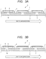
- each of the liquid chambers 6 and the corresponding introduction port 9 are formed such that the width of the liquid chamber 6 and that of the introduction port 9 substantially agree with each other as viewed in the lateral direction of the corresponding recording element substrate 1.
- the introduction ports 9 are so arranged as to be located at the center positions of the respective liquid chambers 6 as viewed in the longitudinal direction of the liquid chambers 6 as illustrated in FIG. 3A .
- the introduction ports 9 may alternatively be arranged at respective positions that are offset toward the upstream side of the liquid chambers 6 as illustrated in FIG. 3B if the desired effects can be obtained by arranging those ports at the upstream side.
- Each of the recording element substrates 1 is provided with heaters 13 (see FIG. 5 ) that are energy generating elements for generating energy to be utilized to eject liquid.
- the support members 4 are preferably formed by using highly thermally insulating members such as resin-made members so that the heat generated by the heaters 13 in the recording element substrates 1 may hardly be conducted to the base substrate 2 including the common flow channel 3 in the base substrate 2. This arrangement provides an effect of minimizing the temperature difference of the liquid flowing in the common flow channel 3 between the upstream end and the downstream end. In other words, the temperature difference in the liquid flowing toward the ejection ports 11 (see FIG.
- the liquid ejection head 5 can be minimized and hence the quantity difference among the liquid droplets that are ejected per unit time from the liquid ejection head 5 can be reduced so that high quality images that are practically free from image irregularities can be recorded. Additionally, due to the thermal insulation effect of the support members 4, if the recording element substrates 1 generate heat to a large extent at the time of high speed recording, the quantity of heat that is conducted to the liquid circulating through the common flow channel 3 can be suppressed to a minimal level. Therefore, the circulating liquid represents minimal temperature changes and hence the liquid temperature control tank 22 (see FIG. 9 ) that is mounted in the recording apparatus main body along with the liquid ejection head 5 can be operated at a minimal power consumption rate.
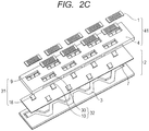
- each support member 4 When the thermal conductivity in the directions running along the main surface of each support member 4 can be made low, support members 4, each of which supports a plurality of recording element substrates 1 as illustrated in FIG. 2C , may alternatively be employed. This arrangement provides an advantage of reducing the number of components of the liquid ejection head 5.
- FIG. 4 is a schematic perspective view of a recording element substrate 1
- FIG. 5 is a schematic cross sectional view of the recording element substrate taken along line 5-5 in FIG. 4 .
- the expressions of "lateral direction” and “longitudinal direction” may appear and they refer to the respective directions indicated in FIG. 4 .
- a total of eight ejection port rows 17, each having a plurality of ejection ports 11 that eject liquid such as ink, are formed in each recording element substrate 1.
- Electric wiring (not illustrated) is provided in the inside of the heater board 16.
- the electric wiring is electrically connected to the lead electrode of an FPC (flexible print circuit) (not illustrated) arranged on the base substrate 2 or the electrode (not illustrated) arranged in the base substrate 2.
- FPC flexible print circuit
- the heaters 13 are heated to boil the liquid in the foaming chambers 12. Then, liquid droplets are ejected from the selected ejection ports 11.
- the plurality of recording element substrates 1 of the liquid ejection head 5 of this embodiment are arranged in rows that run in parallel with each other in the lateral direction of the liquid ejection head 5 and the positions of the recording element substrates 1 in a row are shifted from those of the recording element substrates in the rows located next to the former one in the lateral direction of the liquid ejection head such that the recording element substrates 1 are arranged in a zigzag manner as viewed in the longitudinal direction of the liquid ejection head 5.
- the recording element substrates 1 do not necessarily need to be arranged in a zigzag manner.
- recording element substrates may alternatively be arranged linearly in rows that run in the longitudinal direction or obliquely relative to the longitudinal direction of the liquid ejection head 5 with a certain angle.
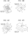
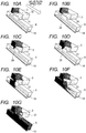
- FIGS. 6A and 6C illustrate the first design alternative of introduction port 9.
- FIGS. 6A and 6C are schematic perspective views of support members 4 as viewed from the side of the corresponding recording element substrates 1.
- FIGS. 6B and 6D are schematic perspective views of the support members 4 as viewed from the side of the base substrate 2.
- FIGS. 6A and 6B illustrate an instance where a single support member 4 is provided with two liquid chambers 6. In other words, with the arrangement illustrated in FIGS. 4 and 5 , liquid is supplied from each liquid chamber 6 to two of the four liquid supply ports 14 of a single recording element substrate 1.
- FIGS. 6C and 6D illustrate an instance where a single support member 4 is provided with a single liquid chamber 6. In other words, with the arrangement illustrated in FIGS. 4 and 5 , liquid is supplied from a single liquid chamber 6 to all the four liquid supply ports 14 of a single recording element substrate 1.
- the liquid that is driven to get into the corresponding liquid chamber 6 from the upstream of the common flow channel 3 firstly touches the introduction port upstream side notch portion 30. Then, because liquid can easily be sucked into the liquid chamber 6 from the introduction port upstream side notch portion 30 by capillary force, a situation where the entire introduction port 9 is covered with liquid can be prevented from taking place.
- the liquid chamber 6 can be filled with liquid, while allowing the air in the liquid chamber 6 to escape into the common flow channel 3. In other words, the liquid chamber 6 can be filled with ink so as to minimize the residual air bubbles.
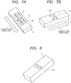
- the notch portion 30 of each of the introduction ports 9 illustrated in FIG. 7A is formed from one of the opposite ends of the corresponding recording element substrate 1 as viewed in the lateral direction of the substrate 1 to proceed in the longitudinal direction of the substrate 1.
- the introduction port upstream side notch portion 30 is formed at the side of one of the opposite ends of the introduction port 9 as viewed in the direction orthogonal to the flow direction of liquid flowing through the common flow channel.
- the introduction port 9 is asymmetrical relative to the center line of the introduction port 9 running along the flow direction of liquid flowing through the common flow channel 3.
- the upstream side profile of the opening that operates as the introduction port 9 is asymmetrical relative to a straight line passing through the center of gravity of the opening and running along the liquid flow direction.
- a temperature control tank 22, a circulation pump 19, a feed pump 20, a filter 21, a liquid tank 23 and so on are provided in a recording apparatus that includes a liquid ejection head 5 according to the present invention.
- the flow-in port 7 for supplying liquid to the common flow channel 3 is linked to a resin tube that communicates with the temperature control tank 22, while the flow-out port 8 for flowing liquid out of the common flow channel 3 is linked to another tube that communicates with the circulation pump 19.
- the circulation pump 19 is put into operation to circulate the liquid in the common flow channel 3.
- the temperature control tank 22 is linked to a heat exchanger (not illustrated) so that it can be subjected to heat exchange operations.
- the temperature control tank 22 has a function of supplying liquid to the liquid ejection head 5 and at the same time maintaining the temperature of the liquid that circulates through the circulation pump 19 to a constant temperature level.
- the temperature control tank 22 is provided with a hole (not illustrated) for communicating with the open air.
- the temperature control tank 22 additionally has a function of expelling bubbles in the liquid in the tank to the outside.
- the temperature of the liquid flowing out from the flow-out port 8 is controlled and regulated by the temperature control tank 22 before the liquid is directed toward the flow-in port 7 and hence the temperature of the liquid located at the position of the flow-in port 7 can always be held within a certain temperature range.
- the target temperature for the temperature control operation of the temperature control tank 22 may be lowered so as to supply liquid to the liquid ejection head 5 at a relatively low temperature.
- the feed pump 20 can transfer liquid from the liquid tank 23 that stores liquid to the temperature control tank 22 after removing the foreign objects contained in the liquid by means of the filter 21 so as to supply liquid to the temperature control tank 22 in order to make up for the liquid consumed by the liquid ejection head 5 as a result of an image recording operation.
- a liquid drop portion 29 is formed from liquid by the capillary force generated at the branch port upstream side notch portion 32 and penetrates into the liquid chamber 6 by way of the branch port upstream side notch portion 32 as illustrated in FIG. 10C .
- the branch port 31 is not blocked by the liquid that is being filled into the liquid chamber 6 and hence a route through which the air in the liquid chamber 6 is discharged to the common flow channel 3 is secured so that liquid can successfully be introduced into the liquid chamber 6.
- the liquid drop portion 29 is guided to one of the lateral walls of the liquid chamber 6 as viewed in the lateral direction of the recording element substrate 1 as illustrated in FIG. 10D . Thereafter, the liquid drop portion 29 slips down by its own weight to the bottom surface (the surface communicating with the liquid supply port 14) of the liquid chamber 6 by way of the lateral wall as illustrated in FIG. 10E .
- a liquid flow route is established from the common flow channel 3 to the bottom surface of the liquid chamber 6 by way of the branch port upstream side notch portion 32 and only one of the lateral walls of the liquid chamber 6 that are disposed oppositely in the lateral direction of the recording element substrate 1.
- a route through which the air found in the liquid chamber 6 can escape is secured at the side of the lateral wall of the common flow channel 3 that is not wet by liquid, or in other words, at the side of one of the lateral walls of the common flow channel 3 that are disposed oppositely in the lateral direction of the recording element substrate 1.
- FIGS. 11A through 11G While the dimensions of the liquid chamber 6 in FIGS. 11A through 11G may appear to be different from those of the liquid chamber in FIGS. 10A through 10G for this reason, the dimensions of the liquid chamber 6 that were employed for the simulation of FIGS. 11A through 11G are exactly the same as those of the liquid chamber 6 of FIGS. 10A through 10G .
- FIGS. 11A through 11G are not necessarily made to respectively correspond to the FIGS. 10A through 10G in terms of the elapse of time from the start of the liquid filling operation.
- FIG. 11A As the liquid filling operation of filling the liquid chamber with liquid from the common flow channel 3 is started as illustrated in FIG. 11A , liquid firstly gets to the branch port 31 as illustrated in FIG. 11B . As the liquid filling operation is continued, a liquid drop portion 29 is formed in the branch port 31 as illustrated in FIG. 11C . Note, however, that FIG. 11C differs from FIG. 10C in that the liquid drop portion 29 is formed as liquid flows from the branch port 31 along the two lateral walls that are oppositely disposed in the lateral direction of the liquid chamber 6. Note that, while it may appear that the liquid drop portion 29 touches only one of the lateral walls of the liquid chamber 6 in FIG. 11C , the liquid drop portion 29 also touches the other lateral wall as a matter of fact for the reason pointed out above although not illustrated, more specifically because FIGS. 11A through 11G illustrate the results obtained by a simulation using a plane of mirror symmetry.
- branch port upstream side notch portion 32 an introduction port upstream side notch portion 30
- introduction port 9 an introduction port upstream side notch portion 30
- each support member 4 is provided with a spacer 24 and pin holes 25 at the surface facing a corresponding recording element substrate 1.
- an FPC is arranged on and supported by the spacer 24 and electrically connected to the recording element substrate 1.
- the pin holes 25 are holes through which respective positioning pins (not illustrated) are made to pass when the support member 4 is mounted on a base substrate 2 in order to secure the positional accuracy of the support member 4 on the base substrate 2.
- the spacer 24 improves the reliability of the electrical connection between the FPC and the recording element substrate 1 while the pin holes have a function of allowing the support member 4 to be easily and accurately mounted on the base substrate 2.
- the regions of an image recorded by the line head that correspond to the gaps separating the recording element substrates 1 are required to represent an image quality comparable to the image quality of the regions that correspond to the recording element substrates 1.
- reducing the gap D separating each upstream side row of recording element substrates 1 and the immediately following downstream side row of recording element substrates 1 in the direction of transporting recording mediums will be effective. In other words, if the gap D is large, the influence of a shift of liquid hitting position due to a slippage on the part of the recording medium on which an image is being recorded increases.
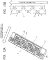
- FIG. 13B is a schematic perspective view of the base substrate 2 of this embodiment as viewed from the side of the surface thereof on which support members 4 are arranged. Note that the common flow channel 3 in the base substrate 2 is represented by broken lines.
- each distribution port 18 of the base substrate 2 has a profile same as that of the introduction port 9 of the corresponding support member 4 that communicates with the distribution port 18.
- each support member 4 is provided with two liquid chambers 6 and each of the liquid chambers 6 is provided with a distribution port 18.
- each distribution port 18 (branch port 31) is formed at a position shifted from the center line running along the longitudinal direction of the corresponding support member 4 (ejection member 41).
- This description also applies to each introduction port 9.
- the distribution port upstream side notch portions 10 and the distribution port downstream side notch portions 36 are formed such that the profile of the distribution port 18 arranged to correspond to a support member 4 and that of the distribution port 18 arranged to correspond to a support member 4 located next to the former distribution port 18 in a direction orthogonal relative to the longitudinal direction of the liquid ejection head are rotationally symmetrical.
- a distribution port upstream side notch portion 10 needs to be arranged in the corresponding distribution port 18. Therefore, although not illustrated, the profile of the introduction port 9 of a support member 4 and that of the introduction port 9 of the support member 4 located next to the former support member 4 in a direction orthogonal relative to the longitudinal direction of the liquid ejection head 5 are also rotationally symmetrical.
- support members 4 having a same profile can be used for upstream side rows of support members and also for downstream side rows of support members as viewed in the direction of transporting recording mediums even when support members 4 having asymmetrical profiles as illustrated in FIG. 13A are employed.
- common parts can be used for those members so that the manufacturing cost of liquid ejection heads 5 can be reduced.
Landscapes
- Particle Formation And Scattering Control In Inkjet Printers (AREA)
- Ink Jet (AREA)
Claims (17)
- Flüssigkeitsausstoßkopf (5), umfassend:mehrere Ausstoßelemente (41), die jeweils eine Ausstoßöffnung (11) zum Ausstoßen von Flüssigkeit und eine Flüssigkeitskammer (6) zum Zuführen von Flüssigkeit zur Ausstoßöffnung aufweisen;ein Basissubstrat (2), das die mehreren Ausstoßelemente auf seiner Oberfläche trägt; undeinen im Basissubstrat gebildeten und entlang der Oberfläche verlaufenden gemeinsamen Strömungskanal (3) zum Zuführen von Flüssigkeit zu den mehreren Flüssigkeitskammern;weiterhin umfassend:mehrere Abzweigöffnungen (31), die jeweils den gemeinsamen Strömungskanal und eine jeweilige Flüssigkeitskammer in einer Richtung senkrecht zur Oberfläche des Basissubstrats direkt miteinander verbinden, um so dem gemeinsamen Strömungskanal Kommunikation mit der Flüssigkeitskammer zu ermöglichen, wobeiin der Richtung senkrecht zur Oberfläche des Basissubstrats gesehen eine jeweilige der Abzweigöffnungen ein sich verjüngendes Profil an einer stromaufwärtigen Seite bezüglich einer Strömungsrichtung von durch den gemeinsamen Strömungskanal strömender Flüssigkeit aufweist, wobei das sich verjüngende Profil durch einen Einkerbungsabschnitt (32) vorgesehen ist.
- Flüssigkeitsausstoßkopf (5) nach Anspruch 1, wobei
in der Richtung senkrecht zur Oberfläche des Basissubstrats gesehen der Einkerbungsabschnitt (32) einer jeweiligen Abzweigöffnung (31) an einem von gegenüberliegenden Enden der Abzweigöffnung bezüglich einer Richtung senkrecht zur Strömungsrichtung der durch den gemeinsamen Strömungskanal (3) strömenden Flüssigkeit angeordnet ist. - Flüssigkeitsausstoßkopf (5) nach Anspruch 1 oder 2, wobei in der Richtung senkrecht zur Oberfläche des Basissubstrats gesehen eine jeweilige der Abzweigöffnungen (31) ein Profil aufweist, das bezüglich einer Mittellinie der Abzweigöffnung (31) asymmetrisch ist, die entlang der Strömungsrichtung der durch den gemeinsamen Strömungskanal (3) strömenden Flüssigkeit verläuft.
- Flüssigkeitsausstoßkopf (5) nach einem der Ansprüche 1 bis 3, wobei in der Richtung senkrecht zur Oberfläche des Basissubstrats gesehen ein anderer Einkerbungsabschnitt (37) an einer stromabwärtigen Seite einer jeweiligen der Abzweigöffnungen (31) bezüglich der Strömungsrichtung von durch den gemeinsamen Strömungskanal (3) strömender Flüssigkeit ausgebildet ist, sodass die jeweilige Abzweigöffnung auch an der stromabwärtigen Seite ein sich verjüngendes Profil aufweist.
- Flüssigkeitsausstoßkopf (5) nach einem der Ansprüche 1 bis 4, wobei mindestens ein Einkerbungsabschnitt (32, 37) einer jeweiligen der Abzweigöffnungen (31) ein Profil aufweist, das durch Einkerben der jeweiligen stromaufwärtigen oder stromabwärtigen Seite der Abzweigöffnung geformt ist.
- Flüssigkeitsausstoßkopf (5) nach einem der Ansprüche 1 bis 4, wobei in der Richtung senkrecht zur Oberfläche des Basissubstrats gesehen mindestens ein Einkerbungsabschnitt (32, 37) einer jeweiligen der Abzweigöffnungen (31) ein Profil aufweist, das durch Neigen der gesamten jeweiligen stromaufwärtigen oder stromabwärtigen Seite der Abzweigöffnung zu einer Richtung senkrecht bezüglich der Strömungsrichtung von durch den gemeinsamen Strömungskanal (3) strömender Flüssigkeit geformt ist.
- Flüssigkeitsausstoßkopf (5) nach einem der Ansprüche 1 bis 6, wobeidie Ausstoßelemente (41) auf dem Basissubstrat (2) zickzackartig entlang einer Längsrichtung des Basissubstrats angeordnet sind, währendeine einzelne Flüssigkeitskammer (6) in einem jeweiligen der Ausstoßelemente angeordnet ist, undin der Richtung senkrecht zur Oberfläche des Basissubstrats gesehen das Profil der in einem jeweiligen der Ausstoßelemente (41) angeordneten Abzweigöffnung (31) und jenes der Abzweigöffnung, die in einem Ausstoßelement angeordnet ist, das in einer Richtung senkrecht bezüglich der Längsrichtung neben dem vorherigen Ausstoßelement positioniert ist, rotationssymmetrisch sind.
- Flüssigkeitsausstoßkopf (5) nach einem der Ansprüche 1 bis 6, wobeidie Ausstoßelemente (41) auf dem Basissubstrat (2) zickzackartig entlang einer Längsrichtung des Basissubstrats angeordnet sind, währendmehrere Flüssigkeitskammern (6) in einem jeweiligen der Ausstoßelemente angeordnet sind, undin der Richtung senkrecht zur Oberfläche des Basissubstrats gesehen das Profil der in einem jeweiligen der Ausstoßelemente angeordneten mehreren Abzweigöffnungen (31) und jenes der mehreren Abzweigöffnungen, die im Ausstoßelement angeordnet sind, welches in einer Richtung senkrecht bezüglich der Längsrichtung neben dem vorherigen Ausstoßelement positioniert ist, rotationssymmetrisch sind.
- Flüssigkeitsausstoßkopf (5) nach Anspruch 7, wobei in der Richtung senkrecht zur Oberfläche des Basissubstrats gesehen die Abzweigöffnung (31) eines jeweiligen der Ausstoßelemente (41) an einer Position gebildet wird, die von der entlang der Längsrichtung verlaufenden Mittellinie des Ausstoßelements verschoben ist.
- Flüssigkeitsausstoßkopf (5) nach einem der Ansprüche 1 bis 9, wobeieine jeweilige der Abzweigöffnungen (31) enthält: eine Einführöffnung (9), die im entsprechenden Ausstoßelement (41) angeordnet ist und mit der Flüssigkeitskammer (6) kommuniziert, und eine im Basissubstrat (2) angeordnete und mit dem gemeinsamen Strömungskanal (3) kommunizierende Verteilungsöffnung (18), wobei die Einführöffnung und die Verteilungsöffnung miteinander kommunizieren, unddas Basissubstrat mit einer Einströmöffnung (7), um Flüssigkeit das Einströmen in den gemeinsamen Strömungskanal zu ermöglichen, sowie einer Ausströmöffnung (8), um Flüssigkeit das Ausströmen aus dem gemeinsamen Strömungskanal zu ermöglichen, versehen ist.
- Flüssigkeitsausstoßkopf (5) nach einem der Ansprüche 1 bis 10, wobeiein jeweiliges der Ausstoßelemente (41) ein Aufzeichnungselementsubstrat (1) und ein Stützelement (4) aufweist, unddie Ausstoßöffnung (11) eines jeweiligen der Ausstoßelemente im Aufzeichnungselementsubstrat desselben gebildet ist, wohingegen die Flüssigkeitskammer (6) im Stützelement gebildet ist, unddas Aufzeichnungselementsubstrat eines jeweiligen der Ausstoßelemente mit einer Flüssigkeitszuführöffnung (14) zum Zuführen von Flüssigkeit von der Flüssigkeitskammer zur Ausstoßöffnung versehen ist.
- Flüssigkeitsausstoßkopf (5) nach einem der Ansprüche 1 bis 10, wobeiein jeweiliges der Ausstoßelemente (41) ein Aufzeichnungselementsubstrat (1) aufweist, in dem die Ausstoßöffnung (11) des Ausstoßelements gebildet ist,die Aufzeichnungselementsubstrate der mehreren Ausstoßelemente durch ein gemeinsames Stützelement (4) gestützt werden, in dem die Flüssigkeitskammer (6) eines jeweiligen Ausstoßelements gebildet ist, undein jeweiliges Aufzeichnungselementsubstrat mit einer Flüssigkeitszuführöffnung (14) zum Zuführen von Flüssigkeit von der jeweiligen Flüssigkeitskammer zur jeweiligen Ausstoßöffnung versehen ist.
- Flüssigkeitsausstoßkopf (5) nach einem der Ansprüche 1 bis 12, wobei in der Richtung senkrecht zur Oberfläche des Basissubstrats gesehen die mehreren Ausstoßelemente (41) entlang des gemeinsamen Strömungskanals (3) angeordnet sind.
- Flüssigkeitsausstoßkopf (5), umfassend:mehrere Ausstoßelemente (41), die jeweils eine Ausstoßöffnung (11) zum Ausstoßen von Flüssigkeit und eine Flüssigkeitskammer (6) zum Speichern von der Ausstoßöffnung zuzuführender Flüssigkeit aufweisen;ein Stützelement (4), das die mehreren Ausstoßelemente stützt;ein Basissubstrat (2), das auf seiner Oberfläche das Stützelement trägt; undeinen im Basissubstrat gebildeten und entlang der Oberfläche verlaufenden gemeinsamen Strömungskanal (3) zum Zuführen von Flüssigkeit zu den mehreren Flüssigkeitskammern;wobei
der gemeinsame Strömungskanal mit den mehreren Flüssigkeitskammern durch jeweilige Öffnungen (9, 18) kommuniziert, die in einer Richtung senkrecht zur Oberfläche des Basissubstrats den gemeinsamen Strömungskanal und eine jeweilige Flüssigkeitskammer direkt miteinander verbinden, undin der Richtung senkrecht zur Oberfläche des Basissubstrats gesehen eine stromaufwärtige Seite einer jeweiligen der Öffnungen bezüglich einer Strömungsrichtung von durch den gemeinsamen Strömungskanal strömender Flüssigkeit ein sich verjüngendes Profil aufweist, das bezüglich einer Mittellinie der jeweiligen Öffnung asymmetrisch ist, die entlang einer Strömungsrichtung von durch den gemeinsamen Strömungskanal strömender Flüssigkeit verläuft. - Flüssigkeitsausstoßkopf (5) nach Anspruch 14, wobei
ein ausgeschnittener Abschnitt (30) in einer jeweiligen der Öffnungen (9) an deren stromaufwärtiger Seite gebildet ist. - Flüssigkeitsausstoßkopf (5) nach Anspruch 14 oder 15, wobei in der Richtung senkrecht zur Oberfläche des Basissubstrats gesehen ein zweiter ausgeschnittener Abschnitt (35) in einer jeweiligen der Öffnungen (9) an einer stromabwärtigen Seite derselben bezüglich der Strömungsrichtung von durch den gemeinsamen Strömungskanal (3) strömender Flüssigkeit gebildet ist.
- Flüssigkeitsausstoßkopf (5) nach einem der Ansprüche 1 bis 16, wobei
die mehreren Ausstoßöffnungen (11) entlang des gemeinsamen Strömungskanals (3) angeordnet sind.
Applications Claiming Priority (1)
| Application Number | Priority Date | Filing Date | Title |
|---|---|---|---|
| JP2013196836 | 2013-09-24 |
Publications (2)
| Publication Number | Publication Date |
|---|---|
| EP2853397A1 EP2853397A1 (de) | 2015-04-01 |
| EP2853397B1 true EP2853397B1 (de) | 2019-09-18 |
Family
ID=51582229
Family Applications (1)
| Application Number | Title | Priority Date | Filing Date |
|---|---|---|---|
| EP14003237.6A Not-in-force EP2853397B1 (de) | 2013-09-24 | 2014-09-18 | Flüssigkeitsausstoßkopf |
Country Status (5)
| Country | Link |
|---|---|
| US (1) | US9469111B2 (de) |
| EP (1) | EP2853397B1 (de) |
| JP (1) | JP6381355B2 (de) |
| KR (1) | KR101779246B1 (de) |
| CN (1) | CN104441992B (de) |
Families Citing this family (16)
| Publication number | Priority date | Publication date | Assignee | Title |
|---|---|---|---|---|
| US20120010445A1 (en) | 2010-07-09 | 2012-01-12 | Celanese International Corporation | Low Energy Alcohol Recovery Processes |
| JP6463034B2 (ja) * | 2013-09-24 | 2019-01-30 | キヤノン株式会社 | 液体吐出ヘッド |
| JP6270533B2 (ja) | 2014-02-25 | 2018-01-31 | キヤノン株式会社 | 液体吐出ヘッド、記録装置、および液体吐出ヘッドの放熱方法 |
| JP6422366B2 (ja) | 2014-05-13 | 2018-11-14 | キヤノン株式会社 | 液体吐出ヘッド及び記録装置 |
| US9931845B2 (en) | 2016-01-08 | 2018-04-03 | Canon Kabushiki Kaisha | Liquid ejection module and liquid ejection head |
| JP6987497B2 (ja) * | 2016-01-08 | 2022-01-05 | キヤノン株式会社 | 液体吐出モジュールおよび液体吐出ヘッド |
| JP6750855B2 (ja) | 2016-05-27 | 2020-09-02 | キヤノン株式会社 | 液体吐出ヘッドおよび液体吐出装置 |
| WO2018056290A1 (ja) * | 2016-09-20 | 2018-03-29 | 京セラ株式会社 | 液体吐出ヘッド、および記録装置 |
| JP6961404B2 (ja) | 2017-06-29 | 2021-11-05 | キヤノン株式会社 | 液体吐出ヘッドおよび液体吐出装置 |
| JP7057071B2 (ja) | 2017-06-29 | 2022-04-19 | キヤノン株式会社 | 液体吐出モジュール |
| JP7019318B2 (ja) | 2017-06-29 | 2022-02-15 | キヤノン株式会社 | 液体吐出ヘッドおよび液体吐出装置 |
| JP6949586B2 (ja) | 2017-06-30 | 2021-10-13 | キヤノン株式会社 | 液体吐出ヘッド、液体吐出装置及び液体吐出ヘッドの製造方法 |
| JP7019328B2 (ja) * | 2017-07-07 | 2022-02-15 | キヤノン株式会社 | 液体吐出ヘッド |
| JP7039231B2 (ja) | 2017-09-28 | 2022-03-22 | キヤノン株式会社 | 液体吐出ヘッドおよび液体吐出装置 |
| WO2019177581A1 (en) * | 2018-03-12 | 2019-09-19 | Hewlett-Packard Development Company, L.P. | Fluid ejection dies |
| US11597204B2 (en) | 2019-06-25 | 2023-03-07 | Hewlett-Packard Development Company, L.P. | Fluid ejection polymeric recirculation channel |
Family Cites Families (12)
| Publication number | Priority date | Publication date | Assignee | Title |
|---|---|---|---|---|
| JP2976479B2 (ja) | 1990-04-17 | 1999-11-10 | セイコーエプソン株式会社 | インクジェットヘッド |
| DE69210509T2 (de) | 1991-08-29 | 1996-09-12 | Hewlett Packard Co | Leckfreies Farbstrahlaufzeichnungsgerät |
| US6328423B1 (en) * | 1999-08-16 | 2001-12-11 | Hewlett-Packard Company | Ink jet cartridge with integrated circuitry |
| US6979077B2 (en) | 2002-02-20 | 2005-12-27 | Brother Kogyo Kabushiki Kaisha | Ink-jet head and ink-jet printer having ink-jet head |
| TWI246115B (en) | 2004-01-16 | 2005-12-21 | Benq Corp | Method for fabricating an enlarged fluid chamber using multiple sacrificial layers |
| US7380920B2 (en) * | 2004-08-30 | 2008-06-03 | Xerox Corporation | Ink jet apparatus |
| JP2007283549A (ja) * | 2006-04-13 | 2007-11-01 | Canon Inc | インクジェット記録ヘッドおよびインクジェット記録ヘッドの製造方法 |
| JP5046841B2 (ja) * | 2007-10-03 | 2012-10-10 | キヤノン株式会社 | インクジェット記録ヘッド |
| JP2009149055A (ja) * | 2007-11-30 | 2009-07-09 | Canon Inc | インクジェット記録ヘッド及びインクジェット記録装置 |
| BRPI0912158A2 (pt) | 2008-05-22 | 2015-10-13 | Fujifilm Corp | dispositivo acionável com pastilha e elemento de circuito integrado |
| US8157352B2 (en) | 2009-02-26 | 2012-04-17 | Fujifilm Corporation | Fluid ejecting with centrally formed inlets and outlets |
| JP5656451B2 (ja) | 2010-05-14 | 2015-01-21 | キヤノン株式会社 | 液体吐出ヘッド及び電気配線基板 |
-
2014
- 2014-08-11 JP JP2014163551A patent/JP6381355B2/ja active Active
- 2014-09-04 US US14/477,021 patent/US9469111B2/en active Active
- 2014-09-16 KR KR1020140122654A patent/KR101779246B1/ko not_active Expired - Fee Related
- 2014-09-18 EP EP14003237.6A patent/EP2853397B1/de not_active Not-in-force
- 2014-09-24 CN CN201410495658.4A patent/CN104441992B/zh not_active Expired - Fee Related
Non-Patent Citations (1)
| Title |
|---|
| None * |
Also Published As
| Publication number | Publication date |
|---|---|
| EP2853397A1 (de) | 2015-04-01 |
| JP6381355B2 (ja) | 2018-08-29 |
| KR20150033541A (ko) | 2015-04-01 |
| US20150085018A1 (en) | 2015-03-26 |
| KR101779246B1 (ko) | 2017-09-18 |
| US9469111B2 (en) | 2016-10-18 |
| CN104441992A (zh) | 2015-03-25 |
| JP2015085676A (ja) | 2015-05-07 |
| CN104441992B (zh) | 2017-01-11 |
Similar Documents
| Publication | Publication Date | Title |
|---|---|---|
| EP2853397B1 (de) | Flüssigkeitsausstoßkopf | |
| EP2853398B1 (de) | Flüssigkeitsausstoßkopf | |
| US8657420B2 (en) | Fluid recirculation in droplet ejection devices | |
| JP6358963B2 (ja) | インクの再循環 | |
| CN109080265B (zh) | 具有流体喷射孔的流体喷射装置 | |
| US8403465B2 (en) | Apparatus for reducing crosstalk in the supply and return channels during fluid droplet ejecting | |
| CN107009748A (zh) | 打印设备 | |
| CN107009747A (zh) | 打印设备和打印方法 | |
| CN109414933B (zh) | 喷墨记录装置 | |
| CN106985529B (zh) | 液体排出头和液体排出方法 | |
| US10486421B2 (en) | Liquid discharging head and liquid discharging device | |
| JP2009039914A (ja) | 液体吐出ヘッド | |
| US10836164B2 (en) | Ink jet head and ink jet recording apparatus | |
| JP5905485B2 (ja) | インクジェットプリントヘッド用インクマニホールド | |
| JP7259417B2 (ja) | 液体吐出ヘッドおよび液体吐出装置 | |
| JP2017144572A (ja) | 液体吐出ヘッド、液体吐出装置及び液体吐出ヘッドの液体充填方法 | |
| US20080180488A1 (en) | Liquid transporting apparatus and printer | |
| JP5451910B2 (ja) | 液体吐出ヘッド | |
| JP5183820B2 (ja) | 液体吐出ヘッド |
Legal Events
| Date | Code | Title | Description |
|---|---|---|---|
| PUAI | Public reference made under article 153(3) epc to a published international application that has entered the european phase |
Free format text: ORIGINAL CODE: 0009012 |
|
| 17P | Request for examination filed |
Effective date: 20140918 |
|
| AK | Designated contracting states |
Kind code of ref document: A1 Designated state(s): AL AT BE BG CH CY CZ DE DK EE ES FI FR GB GR HR HU IE IS IT LI LT LU LV MC MK MT NL NO PL PT RO RS SE SI SK SM TR |
|
| AX | Request for extension of the european patent |
Extension state: BA ME |
|
| R17P | Request for examination filed (corrected) |
Effective date: 20151001 |
|
| RBV | Designated contracting states (corrected) |
Designated state(s): AL AT BE BG CH CY CZ DE DK EE ES FI FR GB GR HR HU IE IS IT LI LT LU LV MC MK MT NL NO PL PT RO RS SE SI SK SM TR |
|
| STAA | Information on the status of an ep patent application or granted ep patent |
Free format text: STATUS: EXAMINATION IS IN PROGRESS |
|
| 17Q | First examination report despatched |
Effective date: 20181008 |
|
| GRAP | Despatch of communication of intention to grant a patent |
Free format text: ORIGINAL CODE: EPIDOSNIGR1 |
|
| STAA | Information on the status of an ep patent application or granted ep patent |
Free format text: STATUS: GRANT OF PATENT IS INTENDED |
|
| INTG | Intention to grant announced |
Effective date: 20190520 |
|
| GRAS | Grant fee paid |
Free format text: ORIGINAL CODE: EPIDOSNIGR3 |
|
| GRAA | (expected) grant |
Free format text: ORIGINAL CODE: 0009210 |
|
| STAA | Information on the status of an ep patent application or granted ep patent |
Free format text: STATUS: THE PATENT HAS BEEN GRANTED |
|
| RAP1 | Party data changed (applicant data changed or rights of an application transferred) |
Owner name: CANON KABUSHIKI KAISHA |
|
| AK | Designated contracting states |
Kind code of ref document: B1 Designated state(s): AL AT BE BG CH CY CZ DE DK EE ES FI FR GB GR HR HU IE IS IT LI LT LU LV MC MK MT NL NO PL PT RO RS SE SI SK SM TR |
|
| REG | Reference to a national code |
Ref country code: GB Ref legal event code: FG4D |
|
| REG | Reference to a national code |
Ref country code: CH Ref legal event code: EP |
|
| REG | Reference to a national code |
Ref country code: DE Ref legal event code: R096 Ref document number: 602014053719 Country of ref document: DE |
|
| REG | Reference to a national code |
Ref country code: AT Ref legal event code: REF Ref document number: 1180805 Country of ref document: AT Kind code of ref document: T Effective date: 20191015 |
|
| REG | Reference to a national code |
Ref country code: IE Ref legal event code: FG4D |
|
| REG | Reference to a national code |
Ref country code: NL Ref legal event code: MP Effective date: 20190918 |
|
| PG25 | Lapsed in a contracting state [announced via postgrant information from national office to epo] |
Ref country code: LT Free format text: LAPSE BECAUSE OF FAILURE TO SUBMIT A TRANSLATION OF THE DESCRIPTION OR TO PAY THE FEE WITHIN THE PRESCRIBED TIME-LIMIT Effective date: 20190918 Ref country code: HR Free format text: LAPSE BECAUSE OF FAILURE TO SUBMIT A TRANSLATION OF THE DESCRIPTION OR TO PAY THE FEE WITHIN THE PRESCRIBED TIME-LIMIT Effective date: 20190918 Ref country code: FI Free format text: LAPSE BECAUSE OF FAILURE TO SUBMIT A TRANSLATION OF THE DESCRIPTION OR TO PAY THE FEE WITHIN THE PRESCRIBED TIME-LIMIT Effective date: 20190918 Ref country code: NO Free format text: LAPSE BECAUSE OF FAILURE TO SUBMIT A TRANSLATION OF THE DESCRIPTION OR TO PAY THE FEE WITHIN THE PRESCRIBED TIME-LIMIT Effective date: 20191218 Ref country code: SE Free format text: LAPSE BECAUSE OF FAILURE TO SUBMIT A TRANSLATION OF THE DESCRIPTION OR TO PAY THE FEE WITHIN THE PRESCRIBED TIME-LIMIT Effective date: 20190918 Ref country code: BG Free format text: LAPSE BECAUSE OF FAILURE TO SUBMIT A TRANSLATION OF THE DESCRIPTION OR TO PAY THE FEE WITHIN THE PRESCRIBED TIME-LIMIT Effective date: 20191218 |
|
| REG | Reference to a national code |
Ref country code: LT Ref legal event code: MG4D |
|
| PG25 | Lapsed in a contracting state [announced via postgrant information from national office to epo] |
Ref country code: RS Free format text: LAPSE BECAUSE OF FAILURE TO SUBMIT A TRANSLATION OF THE DESCRIPTION OR TO PAY THE FEE WITHIN THE PRESCRIBED TIME-LIMIT Effective date: 20190918 Ref country code: GR Free format text: LAPSE BECAUSE OF FAILURE TO SUBMIT A TRANSLATION OF THE DESCRIPTION OR TO PAY THE FEE WITHIN THE PRESCRIBED TIME-LIMIT Effective date: 20191219 Ref country code: AL Free format text: LAPSE BECAUSE OF FAILURE TO SUBMIT A TRANSLATION OF THE DESCRIPTION OR TO PAY THE FEE WITHIN THE PRESCRIBED TIME-LIMIT Effective date: 20190918 Ref country code: LV Free format text: LAPSE BECAUSE OF FAILURE TO SUBMIT A TRANSLATION OF THE DESCRIPTION OR TO PAY THE FEE WITHIN THE PRESCRIBED TIME-LIMIT Effective date: 20190918 |
|
| REG | Reference to a national code |
Ref country code: AT Ref legal event code: MK05 Ref document number: 1180805 Country of ref document: AT Kind code of ref document: T Effective date: 20190918 |
|
| PG25 | Lapsed in a contracting state [announced via postgrant information from national office to epo] |
Ref country code: AT Free format text: LAPSE BECAUSE OF FAILURE TO SUBMIT A TRANSLATION OF THE DESCRIPTION OR TO PAY THE FEE WITHIN THE PRESCRIBED TIME-LIMIT Effective date: 20190918 Ref country code: ES Free format text: LAPSE BECAUSE OF FAILURE TO SUBMIT A TRANSLATION OF THE DESCRIPTION OR TO PAY THE FEE WITHIN THE PRESCRIBED TIME-LIMIT Effective date: 20190918 Ref country code: NL Free format text: LAPSE BECAUSE OF FAILURE TO SUBMIT A TRANSLATION OF THE DESCRIPTION OR TO PAY THE FEE WITHIN THE PRESCRIBED TIME-LIMIT Effective date: 20190918 Ref country code: PL Free format text: LAPSE BECAUSE OF FAILURE TO SUBMIT A TRANSLATION OF THE DESCRIPTION OR TO PAY THE FEE WITHIN THE PRESCRIBED TIME-LIMIT Effective date: 20190918 Ref country code: RO Free format text: LAPSE BECAUSE OF FAILURE TO SUBMIT A TRANSLATION OF THE DESCRIPTION OR TO PAY THE FEE WITHIN THE PRESCRIBED TIME-LIMIT Effective date: 20190918 Ref country code: EE Free format text: LAPSE BECAUSE OF FAILURE TO SUBMIT A TRANSLATION OF THE DESCRIPTION OR TO PAY THE FEE WITHIN THE PRESCRIBED TIME-LIMIT Effective date: 20190918 Ref country code: PT Free format text: LAPSE BECAUSE OF FAILURE TO SUBMIT A TRANSLATION OF THE DESCRIPTION OR TO PAY THE FEE WITHIN THE PRESCRIBED TIME-LIMIT Effective date: 20200120 Ref country code: IT Free format text: LAPSE BECAUSE OF FAILURE TO SUBMIT A TRANSLATION OF THE DESCRIPTION OR TO PAY THE FEE WITHIN THE PRESCRIBED TIME-LIMIT Effective date: 20190918 |
|
| PG25 | Lapsed in a contracting state [announced via postgrant information from national office to epo] |
Ref country code: IS Free format text: LAPSE BECAUSE OF FAILURE TO SUBMIT A TRANSLATION OF THE DESCRIPTION OR TO PAY THE FEE WITHIN THE PRESCRIBED TIME-LIMIT Effective date: 20200224 Ref country code: SM Free format text: LAPSE BECAUSE OF FAILURE TO SUBMIT A TRANSLATION OF THE DESCRIPTION OR TO PAY THE FEE WITHIN THE PRESCRIBED TIME-LIMIT Effective date: 20190918 Ref country code: CZ Free format text: LAPSE BECAUSE OF FAILURE TO SUBMIT A TRANSLATION OF THE DESCRIPTION OR TO PAY THE FEE WITHIN THE PRESCRIBED TIME-LIMIT Effective date: 20190918 Ref country code: SK Free format text: LAPSE BECAUSE OF FAILURE TO SUBMIT A TRANSLATION OF THE DESCRIPTION OR TO PAY THE FEE WITHIN THE PRESCRIBED TIME-LIMIT Effective date: 20190918 |
|
| REG | Reference to a national code |
Ref country code: CH Ref legal event code: PL |
|
| REG | Reference to a national code |
Ref country code: DE Ref legal event code: R097 Ref document number: 602014053719 Country of ref document: DE |
|
| PLBE | No opposition filed within time limit |
Free format text: ORIGINAL CODE: 0009261 |
|
| STAA | Information on the status of an ep patent application or granted ep patent |
Free format text: STATUS: NO OPPOSITION FILED WITHIN TIME LIMIT |
|
| PG2D | Information on lapse in contracting state deleted |
Ref country code: IS |
|
| PG25 | Lapsed in a contracting state [announced via postgrant information from national office to epo] |
Ref country code: IE Free format text: LAPSE BECAUSE OF NON-PAYMENT OF DUE FEES Effective date: 20190918 Ref country code: LU Free format text: LAPSE BECAUSE OF NON-PAYMENT OF DUE FEES Effective date: 20190918 Ref country code: LI Free format text: LAPSE BECAUSE OF NON-PAYMENT OF DUE FEES Effective date: 20190930 Ref country code: DK Free format text: LAPSE BECAUSE OF FAILURE TO SUBMIT A TRANSLATION OF THE DESCRIPTION OR TO PAY THE FEE WITHIN THE PRESCRIBED TIME-LIMIT Effective date: 20190918 Ref country code: CH Free format text: LAPSE BECAUSE OF NON-PAYMENT OF DUE FEES Effective date: 20190930 Ref country code: IS Free format text: LAPSE BECAUSE OF FAILURE TO SUBMIT A TRANSLATION OF THE DESCRIPTION OR TO PAY THE FEE WITHIN THE PRESCRIBED TIME-LIMIT Effective date: 20200119 |
|
| REG | Reference to a national code |
Ref country code: BE Ref legal event code: MM Effective date: 20190930 |
|
| 26N | No opposition filed |
Effective date: 20200619 |
|
| PG25 | Lapsed in a contracting state [announced via postgrant information from national office to epo] |
Ref country code: BE Free format text: LAPSE BECAUSE OF NON-PAYMENT OF DUE FEES Effective date: 20190930 Ref country code: MC Free format text: LAPSE BECAUSE OF FAILURE TO SUBMIT A TRANSLATION OF THE DESCRIPTION OR TO PAY THE FEE WITHIN THE PRESCRIBED TIME-LIMIT Effective date: 20190918 Ref country code: SI Free format text: LAPSE BECAUSE OF FAILURE TO SUBMIT A TRANSLATION OF THE DESCRIPTION OR TO PAY THE FEE WITHIN THE PRESCRIBED TIME-LIMIT Effective date: 20190918 |
|
| PG25 | Lapsed in a contracting state [announced via postgrant information from national office to epo] |
Ref country code: FR Free format text: LAPSE BECAUSE OF NON-PAYMENT OF DUE FEES Effective date: 20191118 |
|
| PG25 | Lapsed in a contracting state [announced via postgrant information from national office to epo] |
Ref country code: CY Free format text: LAPSE BECAUSE OF FAILURE TO SUBMIT A TRANSLATION OF THE DESCRIPTION OR TO PAY THE FEE WITHIN THE PRESCRIBED TIME-LIMIT Effective date: 20190918 |
|
| PG25 | Lapsed in a contracting state [announced via postgrant information from national office to epo] |
Ref country code: MT Free format text: LAPSE BECAUSE OF FAILURE TO SUBMIT A TRANSLATION OF THE DESCRIPTION OR TO PAY THE FEE WITHIN THE PRESCRIBED TIME-LIMIT Effective date: 20190918 Ref country code: HU Free format text: LAPSE BECAUSE OF FAILURE TO SUBMIT A TRANSLATION OF THE DESCRIPTION OR TO PAY THE FEE WITHIN THE PRESCRIBED TIME-LIMIT; INVALID AB INITIO Effective date: 20140918 |
|
| PG25 | Lapsed in a contracting state [announced via postgrant information from national office to epo] |
Ref country code: TR Free format text: LAPSE BECAUSE OF FAILURE TO SUBMIT A TRANSLATION OF THE DESCRIPTION OR TO PAY THE FEE WITHIN THE PRESCRIBED TIME-LIMIT Effective date: 20190918 |
|
| PG25 | Lapsed in a contracting state [announced via postgrant information from national office to epo] |
Ref country code: MK Free format text: LAPSE BECAUSE OF FAILURE TO SUBMIT A TRANSLATION OF THE DESCRIPTION OR TO PAY THE FEE WITHIN THE PRESCRIBED TIME-LIMIT Effective date: 20190918 |
|
| PGFP | Annual fee paid to national office [announced via postgrant information from national office to epo] |
Ref country code: GB Payment date: 20230823 Year of fee payment: 10 |
|
| PGFP | Annual fee paid to national office [announced via postgrant information from national office to epo] |
Ref country code: DE Payment date: 20230822 Year of fee payment: 10 |
|
| REG | Reference to a national code |
Ref country code: DE Ref legal event code: R119 Ref document number: 602014053719 Country of ref document: DE |
|
| GBPC | Gb: european patent ceased through non-payment of renewal fee |
Effective date: 20240918 |
|
| PG25 | Lapsed in a contracting state [announced via postgrant information from national office to epo] |
Ref country code: DE Free format text: LAPSE BECAUSE OF NON-PAYMENT OF DUE FEES Effective date: 20250401 |
|
| PG25 | Lapsed in a contracting state [announced via postgrant information from national office to epo] |
Ref country code: GB Free format text: LAPSE BECAUSE OF NON-PAYMENT OF DUE FEES Effective date: 20240918 |