EP2853426A2 - Système de levage automatique de couvercle pour un corps de transport - Google Patents
Système de levage automatique de couvercle pour un corps de transport Download PDFInfo
- Publication number
- EP2853426A2 EP2853426A2 EP20140184032 EP14184032A EP2853426A2 EP 2853426 A2 EP2853426 A2 EP 2853426A2 EP 20140184032 EP20140184032 EP 20140184032 EP 14184032 A EP14184032 A EP 14184032A EP 2853426 A2 EP2853426 A2 EP 2853426A2
- Authority
- EP
- European Patent Office
- Prior art keywords
- transport body
- shaft
- cover
- flexible cover
- dump
- Prior art date
- Legal status (The legal status is an assumption and is not a legal conclusion. Google has not performed a legal analysis and makes no representation as to the accuracy of the status listed.)
- Withdrawn
Links
- 238000004804 winding Methods 0.000 claims description 4
- 238000000034 method Methods 0.000 claims description 3
- 239000004033 plastic Substances 0.000 claims description 3
- 239000004411 aluminium Substances 0.000 claims description 2
- 229910052782 aluminium Inorganic materials 0.000 claims description 2
- XAGFODPZIPBFFR-UHFFFAOYSA-N aluminium Chemical compound [Al] XAGFODPZIPBFFR-UHFFFAOYSA-N 0.000 claims description 2
- 229910052751 metal Inorganic materials 0.000 claims description 2
- 239000002184 metal Substances 0.000 claims description 2
- 230000003213 activating effect Effects 0.000 abstract description 3
- 238000005096 rolling process Methods 0.000 description 6
- XLYOFNOQVPJJNP-UHFFFAOYSA-N water Substances O XLYOFNOQVPJJNP-UHFFFAOYSA-N 0.000 description 3
- 230000000694 effects Effects 0.000 description 2
- 238000005265 energy consumption Methods 0.000 description 2
- 239000000446 fuel Substances 0.000 description 2
- 230000006978 adaptation Effects 0.000 description 1
- 238000004140 cleaning Methods 0.000 description 1
- 230000001105 regulatory effect Effects 0.000 description 1
- 230000000717 retained effect Effects 0.000 description 1
Images


Classifications
-
- B—PERFORMING OPERATIONS; TRANSPORTING
- B60—VEHICLES IN GENERAL
- B60J—WINDOWS, WINDSCREENS, NON-FIXED ROOFS, DOORS, OR SIMILAR DEVICES FOR VEHICLES; REMOVABLE EXTERNAL PROTECTIVE COVERINGS SPECIALLY ADAPTED FOR VEHICLES
- B60J5/00—Doors
- B60J5/10—Doors arranged at the vehicle rear
- B60J5/108—Doors arranged at the vehicle rear for load transporting vehicles or public transport, e.g. lorries, trucks, buses
-
- B—PERFORMING OPERATIONS; TRANSPORTING
- B60—VEHICLES IN GENERAL
- B60J—WINDOWS, WINDSCREENS, NON-FIXED ROOFS, DOORS, OR SIMILAR DEVICES FOR VEHICLES; REMOVABLE EXTERNAL PROTECTIVE COVERINGS SPECIALLY ADAPTED FOR VEHICLES
- B60J7/00—Non-fixed roofs; Roofs with movable panels, e.g. rotary sunroofs
- B60J7/08—Non-fixed roofs; Roofs with movable panels, e.g. rotary sunroofs of non-sliding type, i.e. movable or removable roofs or panels, e.g. let-down tops or roofs capable of being easily detached or of assuming a collapsed or inoperative position
- B60J7/085—Non-fixed roofs; Roofs with movable panels, e.g. rotary sunroofs of non-sliding type, i.e. movable or removable roofs or panels, e.g. let-down tops or roofs capable of being easily detached or of assuming a collapsed or inoperative position winding up, e.g. for utility vehicles
Definitions
- the present invention relates to a system for automatic lift of covers for a transport body, such as a platform on a lorry, trailer, or a container, which transport body being covered by at least one flexible cover, which transport body comprises a dump body.
- EP2505399 disclose a cover for a transport body, such as a platform on a lorry, trailer, or a container, the transport body being covered by at least one flexible cover, the cover capable of being rolled up around a shaft by opening, where hydraulic cylinders by means of pivotable arms force the shaft to perform a curving movement above the transport body.
- the purpose of the invention is to provide a reliable automatic device for covering a transport body, thereby ensuring that the cover is applied during all driving with empty as well as full transport body.
- the purpose can be achieved if the flexible cover is fastened to a first of the sides of the transport body, the flexible cover having a fold formed by a rubber strap where the rubber strap is fastened to the flexible cover at both sides of the fold.
- a further object of the pending patent application is to keep the cover in place when activating the dump body.
- the transport body comprises two or more longitudinal side members which longitudinal side members at a first end are pivoted at the top of the sides of the transport body, which longitudinal side members at the second ends are mechanical connected to at least one down ward oriented wheel or wheels, which wheel or wheels are lifted by the dump body by opening the dump body.
- the upper part of the dump body comprise one or more protrusions, which protrusion interacts with at least one of the wheels.
- the wheels such as rails be welded at the top of the dump body and in that way it can be achieved that a standard module for raising the cover of the transport body can be used with different dump bodies in that they can be adapted to get in touch with the wheels at the longitudinal side members.
- a standard module for raising the cover of the transport body can be used with different dump bodies in that they can be adapted to get in touch with the wheels at the longitudinal side members. It is possible by the pending application not to place the wheels directly at the side members but instead place the wheels in relation to a bridge that is connecting the longitudinal side members. At this bridge one or more wheels can be placed which wheels can be in contact with rails placed at the dump body.
- the cover for a transport body be formed as a flexible cover which cover is capable of being rolled up around a shaft by opening, which shaft is interacting with at least one hydraulic cylinder which by means of pilotable arms forces the shaft to perform a curving movement above the transport body, where the shaft is connected with rotary means that rotate the shaft during the curving movement.
- the cover of a transport body can be rolled on and off in an automatic way where for example the lorry driver simply has to activate a hydraulic actuator maybe by a remote control where as soon as the driver has activated the system, the roll or unroll process is performed automatically.
- the flexible cover be fastened to a first of the sides of the transport body, whereby the flexible cover can be fastened to the shaft, that by covering the transport body the shaft bears against the top of the transport body, that the flexible cover has a fold formed by a rubber straps, that the rubber straps are fastened to the flexible cover at both sides of the fold.
- the flexible cover By designing the flexible cover with a fold which is perpetually drawn together by a rubber strap disposed in zig-zag and fastened to both sides of the fold, it is achieved that if the load is higher than allowed by the immediate covering, the flexible cover becomes additionally flexible in that the rubber strap and the fold formed by means of the rubber strap are just extended such that an automatic extension of the flexible cover is provided, either locally where a higher loader is possibly present or along the entire length of the load.
- the flexible cover has the advantage that if water, snow, or ice is accumulated on the flexible cover, a rolling up can be effected automatically and a subsequent automatic unrolling as well, which can be effected in a very few minutes, after which water, snow, or ice will automatically be removed from the flexible cover.
- the flexible cover consists of a permanently mounted first section and a second, roll able section, that the permanently mounted first section has a side which is fastened by at least one flexible fastening means to a first of the sides of the transport body, that the roll able second section of the flexible cover is fastened to the first side of the transport body as well, that the first and second sections of the flexible cover are joined along the fold in the second section of the flexible cover, whereby the fold in the second section is covered by the first section.
- each end of the shaft is seated in a pivotable arm which is provided with a reel arrangement for reeling a wire on and off, that the wire is fastened at one end by a helical spring to the transport body and at the other end wound around the shaft with a direction of winding which is opposite relative to the flexible cover.
- Automatic rotation of the shaft may thus occur by means of a wire such that the shaft rotates automatically during rolling the flexible cover on or off.
- a helical spring automatically has hold of the end of the wire such that a constant tensile force is ensured in the wire.
- each end of the shaft be seated in the pivotable arms where the shaft is connected to a hydraulic motor, that the motor is designed with a torque limiter for adapting the torque on the shaft to winding the flexible cover on or off, respectively.
- a hydraulic system for activating the pivotable arms is already present, it is a matter of course to provide a hydraulic motor with pressure and return lines through the pivotable arms such that the shaft can be rotated by a hydraulic motor.
- the torque to be produced determines the force with which the flexible cover is pulled, it will be expedient if the motor applies a constant torque on the shaft.
- By a suitable choice of regulating valves for the hydraulic motor it will be possible to operate with different torque, depending on whether rolling off or rolling on of the flexible cover is taking place.
- the pivotable arms, hydraulic cylinders, wire devices or hydraulic motor are designed such that they can be mounted at a level on the chassis of the transport body which will enable opening of the transport body at the rear.
- the pivotable arms, hydraulic cylinders, wire devices or hydraulic motor are designed such that they can be mounted at a level on the chassis of the transport body which will enable opening of the transport body at the rear.
- the flexible cover be formed by a segmented tarpaulin where the individual tarpaulin parts preferably are secured by using elastic rubber straps mounted in a zig-zag pattern.
- elastic rubber straps mounted in a zig-zag pattern may entail that a flexible fastening of the tarpaulin parts may occur such that these tarpaulin parts adapt themselves to the load present that may exist on the tarpaulin covering a load.
- the rubber straps will thus under all circumstances keep the tarpaulin in tension, irrespective of the tarpaulin being pushed upwards by too high load or downwards due to ice, snow, or water possibly lying on the tarpaulin.
- the shaft comprise a groove in the pivotable shaft for fastening the cover to the shaft, the groove being formed in an extruded tubular profile, preferably made of plastic, aluminium or metal, with a groove for fastening the cover in the pivotable shaft.
- the design of the shaft of an extruded item provides that shafts can be made in optional lengths, and it becomes possible to produce shafts relatively cheaply but on the other hand very efficiently since it becomes possible to form the shaft with the necessary grooves.
- the shaft may also contain e.g. channels utilised as hydraulic piping internally of the extruded profile.
- the pivotable arms be designed with a bend whereby the shaft and the fastening of the hydraulic cylinder is elevated in relation to the fastening of the pivotable arm on the transport body.
- fastening of the pivotable arms and fastening of the hydraulic cylinder may be provided at the same level on a transport body, whereby it becomes possible to provide pivotable arms and hydraulic cylinder at approximately the same level and in any case above possible doors that can be opened at the end of e.g. a lorry platform.
- a bend on the pivotable arms a positive force can thus obtained at any position for the work of the hydraulic cylinder. It is thus avoided that the hydraulic cylinder becomes locked in a certain situation because pressure appears, e.g. on the arm, where the pressure against the arm is directed towards the fastening centre of the arm, whereby any movement of this arm cannot take place.
- the pending patent application further disclose a method for automatic lift of covers for a transport body as previous disclosed by at first start opening the dump body, let the upper part of the dump body get in touch with the wheels, continue opening of the dump body, lift he wheels and the longitudinal side members.
- the automatic lift of the covers of a transport body is performed in an automatic way where no activity is necessary from the driver or from other personnel.
- a cover of the transport body is kept in place during unloading of the transport body so when a lorry afterwards returns empty the cover of the transport body will still be in place.
- the fuel consumption of the truck be reduced with up to 10%.
- the cover by flexible means is kept straight so aerodynamic induced differences between high and low pressure over the transport body is not letting the cover start fluttering.
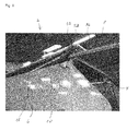
- Fig. 1 discloses one possible embodiment for the invention where a system 2 is seen from the left side of a transport body 6.
- a cover 4 is indicated, but here seen from below, this cover 4 covers a transport body 6.
- a dump body 8 which dump body 8 is open and it is through the opening it is possible to see the cover 4.
- a longitudinal side member left 10 is pivoted at the second end at a pivoting member 18.
- a shaft 32 which shaft 32 is used for unrolling the cover 4.
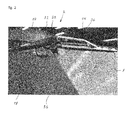
- Fig. 2 shows same embodiment as in fig. 1 , but now in a situation where the dump body is closed.
- the system 2 is therefore to be seen in some more details.
- 8 indicates the dump body and 10 indicates the longitudinal side member left, where 18 indicates the pivoting member of the longitudinal side member left 10.
- the second end 22 of the longitudinal side member left and the wheel 26 which is now not in use.
- the shaft 32 which shaft is carried by the pivotable arm 36, which arm 36 is to be activated by the hydraulic cylinder 34.
- the hydraulic cylinder 34 will when pressurized force the pivotable arm 36 to perform a rotational movement carrying the shaft 32 which performs a rolling activity and rolls the cover around the shaft 32. Returning the operation is performed by pressurizing the opposite end of the hydraulic cylinder 34, which will return the shaft 32 to the indicated position and perform an unrolling of the cover and placing the cover correct above transport body 6.
- Fig. 3 shows the same system 2 as previous described, but now seen from the opposite side.
- the dump body 8 is now open and the cover 4 is indicated through the opening.
- the longitudinal side member right with a number 12. This longitudinal side member right 12 is connected to the pivoted member 20.
- the dump body 8 is able to force the wheel 28 to perform an upwards movement where the longitudinal side member 12 is turning around the pivoting member 20.
- Fig. 4 is an enlarged picture of one possible embodiment for a system 2.
- the dump body 8 and the longitudinal side member right with the number 12.
- This longitudinal side member 12 is hinged at the pivoting member 20.
- the other end 24 of the longitudinal side member right 12 is mechanical connected to the wheel 28. It can be indicated that this wheel is rolling at a track or rail 31.
- the wheels 26 or 28 are placed different in relation to the longitudinal side members.
- the only thing which is important is that the wheels are placed in a way in which they are performing a lift of the side members. Therefore, the wheels can be placed more or less in the centre of the dump body or maybe more wheels could be necessary. In fact only one wheel which has sufficient force placed in the middle will be one possible embodiment for the invention.
Landscapes
- Engineering & Computer Science (AREA)
- Mechanical Engineering (AREA)
- Forklifts And Lifting Vehicles (AREA)
- Handcart (AREA)
Applications Claiming Priority (1)
| Application Number | Priority Date | Filing Date | Title |
|---|---|---|---|
| DK201300558A DK177996B1 (da) | 2013-09-30 | 2013-09-30 | Indretning til automatrisk bagende-løft med automatisk presennings system til lastkasse, for eksempel på en lastbil |
Publications (2)
| Publication Number | Publication Date |
|---|---|
| EP2853426A2 true EP2853426A2 (fr) | 2015-04-01 |
| EP2853426A3 EP2853426A3 (fr) | 2015-04-29 |
Family
ID=51485528
Family Applications (1)
| Application Number | Title | Priority Date | Filing Date |
|---|---|---|---|
| EP20140184032 Withdrawn EP2853426A3 (fr) | 2013-09-30 | 2014-09-09 | Système de levage automatique de couvercle pour un corps de transport |
Country Status (2)
| Country | Link |
|---|---|
| EP (1) | EP2853426A3 (fr) |
| DK (2) | DK177996B1 (fr) |
Cited By (2)
| Publication number | Priority date | Publication date | Assignee | Title |
|---|---|---|---|---|
| US10919368B2 (en) | 2017-09-14 | 2021-02-16 | Ty-Crop Manufacturing Lid. | Apparatus for covering a container load |
| US11535181B2 (en) | 2019-03-05 | 2022-12-27 | Ty-Crop Manufacturing Ltd. | Trailer or container motorized cover powered by supercapacitor |
Family Cites Families (3)
| Publication number | Priority date | Publication date | Assignee | Title |
|---|---|---|---|---|
| US4068892A (en) * | 1976-12-20 | 1978-01-17 | Welch Rafael J | Tail gate apparatus having an offset pivot axis |
| US7669911B1 (en) * | 2006-02-21 | 2010-03-02 | Hankey J Daniel | Tarping system for truck mounted containers |
| FR2987006B1 (fr) * | 2012-02-20 | 2014-02-14 | Afhymat | Dispositif a double articulation de porte arriere de bennes basculantes avec verrouillage incorpore |
-
2013
- 2013-09-30 DK DK201300558A patent/DK177996B1/da not_active IP Right Cessation
-
2014
- 2014-09-09 EP EP20140184032 patent/EP2853426A3/fr not_active Withdrawn
- 2014-09-09 DK DKPA201470554A patent/DK178756B1/da active
Cited By (2)
| Publication number | Priority date | Publication date | Assignee | Title |
|---|---|---|---|---|
| US10919368B2 (en) | 2017-09-14 | 2021-02-16 | Ty-Crop Manufacturing Lid. | Apparatus for covering a container load |
| US11535181B2 (en) | 2019-03-05 | 2022-12-27 | Ty-Crop Manufacturing Ltd. | Trailer or container motorized cover powered by supercapacitor |
Also Published As
| Publication number | Publication date |
|---|---|
| DK201470554A1 (en) | 2015-04-13 |
| EP2853426A3 (fr) | 2015-04-29 |
| DK177996B1 (da) | 2015-02-23 |
| DK178756B1 (en) | 2017-01-02 |
Similar Documents
| Publication | Publication Date | Title |
|---|---|---|
| CA2460703C (fr) | Bache escamotable de camion | |
| AU669565B2 (en) | Swing away support system for a covering | |
| US10071619B2 (en) | Roll tarp system | |
| EP2505399A2 (fr) | Couverture pour une structure de transport | |
| US10005647B2 (en) | Adaptation of a front winch device on a vehicle to raise a load to the rear of a vehicle | |
| EP3458352B1 (fr) | Housse de protection automatique pour embarcation | |
| US7380769B1 (en) | Vehicular cargo loader | |
| EP2853426A2 (fr) | Système de levage automatique de couvercle pour un corps de transport | |
| US7275780B2 (en) | Dual tarp cover system | |
| US7594687B2 (en) | Container truck cover system | |
| WO1998024656A1 (fr) | Dispositif destine a couvrir des compartiments a marchandises | |
| US6499790B1 (en) | Covering system for a trailer and method | |
| AT11244U1 (de) | Abdeckhaube für kraftfahrzeuge | |
| CN2379348Y (zh) | 顶盖折叠伸缩式封闭货运车厢 | |
| AU2006201844B2 (en) | Retractable truck tarpaulin system | |
| JP4291237B2 (ja) | コンテナ等の開閉屋根 | |
| CA3054054C (fr) | Appareil et systeme automatises de bachage | |
| US11155146B2 (en) | Automated tarping device and system | |
| EP4549187A1 (fr) | Système de couvercle enroulable pour un récipient | |
| EP1950068A2 (fr) | Système de couverture pour une remorque | |
| EP2857242B1 (fr) | Dispositif de levage de bâches | |
| WO2006120411A1 (fr) | Systeme de bachage ameliore | |
| ZA200810536B (en) | Covering equipment incorporating trailer | |
| DE202016000284U1 (de) | System aus Plane und Spriegel für Anhänger zum Einfahren mit Motorrädern |
Legal Events
| Date | Code | Title | Description |
|---|---|---|---|
| PUAL | Search report despatched |
Free format text: ORIGINAL CODE: 0009013 |
|
| PUAI | Public reference made under article 153(3) epc to a published international application that has entered the european phase |
Free format text: ORIGINAL CODE: 0009012 |
|
| 17P | Request for examination filed |
Effective date: 20140909 |
|
| AK | Designated contracting states |
Kind code of ref document: A2 Designated state(s): AL AT BE BG CH CY CZ DE DK EE ES FI FR GB GR HR HU IE IS IT LI LT LU LV MC MK MT NL NO PL PT RO RS SE SI SK SM TR |
|
| AX | Request for extension of the european patent |
Extension state: BA ME |
|
| AK | Designated contracting states |
Kind code of ref document: A3 Designated state(s): AL AT BE BG CH CY CZ DE DK EE ES FI FR GB GR HR HU IE IS IT LI LT LU LV MC MK MT NL NO PL PT RO RS SE SI SK SM TR |
|
| AX | Request for extension of the european patent |
Extension state: BA ME |
|
| RIC1 | Information provided on ipc code assigned before grant |
Ipc: B60J 5/10 20060101ALI20150326BHEP Ipc: B60J 7/08 20060101AFI20150326BHEP |
|
| R17P | Request for examination filed (corrected) |
Effective date: 20151027 |
|
| RBV | Designated contracting states (corrected) |
Designated state(s): AL AT BE BG CH CY CZ DE DK EE ES FI FR GB GR HR HU IE IS IT LI LT LU LV MC MK MT NL NO PL PT RO RS SE SI SK SM TR |
|
| GRAP | Despatch of communication of intention to grant a patent |
Free format text: ORIGINAL CODE: EPIDOSNIGR1 |
|
| INTG | Intention to grant announced |
Effective date: 20160517 |
|
| STAA | Information on the status of an ep patent application or granted ep patent |
Free format text: STATUS: THE APPLICATION IS DEEMED TO BE WITHDRAWN |
|
| 18D | Application deemed to be withdrawn |
Effective date: 20160928 |