EP2853672A1 - Porte de véhicule dotée d'un dispositif à came réglable - Google Patents
Porte de véhicule dotée d'un dispositif à came réglable Download PDFInfo
- Publication number
- EP2853672A1 EP2853672A1 EP20140002504 EP14002504A EP2853672A1 EP 2853672 A1 EP2853672 A1 EP 2853672A1 EP 20140002504 EP20140002504 EP 20140002504 EP 14002504 A EP14002504 A EP 14002504A EP 2853672 A1 EP2853672 A1 EP 2853672A1
- Authority
- EP
- European Patent Office
- Prior art keywords
- cam
- door
- door leaf
- locking device
- locking
- Prior art date
- Legal status (The legal status is an assumption and is not a legal conclusion. Google has not performed a legal analysis and makes no representation as to the accuracy of the status listed.)
- Granted
Links
Images


Classifications
-
- E—FIXED CONSTRUCTIONS
- E05—LOCKS; KEYS; WINDOW OR DOOR FITTINGS; SAFES
- E05F—DEVICES FOR MOVING WINGS INTO OPEN OR CLOSED POSITION; CHECKS FOR WINGS; WING FITTINGS NOT OTHERWISE PROVIDED FOR, CONCERNED WITH THE FUNCTIONING OF THE WING
- E05F15/00—Power-operated mechanisms for wings
- E05F15/50—Power-operated mechanisms for wings using fluid-pressure actuators
- E05F15/53—Power-operated mechanisms for wings using fluid-pressure actuators for swinging wings
- E05F15/54—Power-operated mechanisms for wings using fluid-pressure actuators for swinging wings operated by linear actuators acting on a helical track coaxial with the swinging axis
-
- E—FIXED CONSTRUCTIONS
- E05—LOCKS; KEYS; WINDOW OR DOOR FITTINGS; SAFES
- E05D—HINGES OR SUSPENSION DEVICES FOR DOORS, WINDOWS OR WINGS
- E05D15/00—Suspension arrangements for wings
- E05D15/56—Suspension arrangements for wings with successive different movements
- E05D15/58—Suspension arrangements for wings with successive different movements with both swinging and sliding movements
- E05D15/581—Suspension arrangements for wings with successive different movements with both swinging and sliding movements the swinging axis laying in the sliding direction
-
- E—FIXED CONSTRUCTIONS
- E05—LOCKS; KEYS; WINDOW OR DOOR FITTINGS; SAFES
- E05F—DEVICES FOR MOVING WINGS INTO OPEN OR CLOSED POSITION; CHECKS FOR WINGS; WING FITTINGS NOT OTHERWISE PROVIDED FOR, CONCERNED WITH THE FUNCTIONING OF THE WING
- E05F15/00—Power-operated mechanisms for wings
- E05F15/60—Power-operated mechanisms for wings using electrical actuators
- E05F15/603—Power-operated mechanisms for wings using electrical actuators using rotary electromotors
- E05F15/611—Power-operated mechanisms for wings using electrical actuators using rotary electromotors for swinging wings
- E05F15/63—Power-operated mechanisms for wings using electrical actuators using rotary electromotors for swinging wings operated by swinging arms
-
- E—FIXED CONSTRUCTIONS
- E05—LOCKS; KEYS; WINDOW OR DOOR FITTINGS; SAFES
- E05F—DEVICES FOR MOVING WINGS INTO OPEN OR CLOSED POSITION; CHECKS FOR WINGS; WING FITTINGS NOT OTHERWISE PROVIDED FOR, CONCERNED WITH THE FUNCTIONING OF THE WING
- E05F7/00—Accessories for wings not provided for in other groups of this subclass
- E05F7/04—Arrangements affording protection against rattling
-
- E—FIXED CONSTRUCTIONS
- E05—LOCKS; KEYS; WINDOW OR DOOR FITTINGS; SAFES
- E05Y—INDEXING SCHEME ASSOCIATED WITH SUBCLASSES E05D AND E05F, RELATING TO CONSTRUCTION ELEMENTS, ELECTRIC CONTROL, POWER SUPPLY, POWER SIGNAL OR TRANSMISSION, USER INTERFACES, MOUNTING OR COUPLING, DETAILS, ACCESSORIES, AUXILIARY OPERATIONS NOT OTHERWISE PROVIDED FOR, APPLICATION THEREOF
- E05Y2201/00—Constructional elements; Accessories therefor
- E05Y2201/20—Brakes; Disengaging means; Holders; Stops; Valves; Accessories therefor
- E05Y2201/218—Holders
- E05Y2201/22—Locks
-
- E—FIXED CONSTRUCTIONS
- E05—LOCKS; KEYS; WINDOW OR DOOR FITTINGS; SAFES
- E05Y—INDEXING SCHEME ASSOCIATED WITH SUBCLASSES E05D AND E05F, RELATING TO CONSTRUCTION ELEMENTS, ELECTRIC CONTROL, POWER SUPPLY, POWER SIGNAL OR TRANSMISSION, USER INTERFACES, MOUNTING OR COUPLING, DETAILS, ACCESSORIES, AUXILIARY OPERATIONS NOT OTHERWISE PROVIDED FOR, APPLICATION THEREOF
- E05Y2201/00—Constructional elements; Accessories therefor
- E05Y2201/20—Brakes; Disengaging means; Holders; Stops; Valves; Accessories therefor
- E05Y2201/23—Actuation thereof
- E05Y2201/232—Actuation thereof by automatically acting means
-
- E—FIXED CONSTRUCTIONS
- E05—LOCKS; KEYS; WINDOW OR DOOR FITTINGS; SAFES
- E05Y—INDEXING SCHEME ASSOCIATED WITH SUBCLASSES E05D AND E05F, RELATING TO CONSTRUCTION ELEMENTS, ELECTRIC CONTROL, POWER SUPPLY, POWER SIGNAL OR TRANSMISSION, USER INTERFACES, MOUNTING OR COUPLING, DETAILS, ACCESSORIES, AUXILIARY OPERATIONS NOT OTHERWISE PROVIDED FOR, APPLICATION THEREOF
- E05Y2800/00—Details, accessories and auxiliary operations not otherwise provided for
- E05Y2800/10—Additional functions
- E05Y2800/102—Additional wing movements
-
- E—FIXED CONSTRUCTIONS
- E05—LOCKS; KEYS; WINDOW OR DOOR FITTINGS; SAFES
- E05Y—INDEXING SCHEME ASSOCIATED WITH SUBCLASSES E05D AND E05F, RELATING TO CONSTRUCTION ELEMENTS, ELECTRIC CONTROL, POWER SUPPLY, POWER SIGNAL OR TRANSMISSION, USER INTERFACES, MOUNTING OR COUPLING, DETAILS, ACCESSORIES, AUXILIARY OPERATIONS NOT OTHERWISE PROVIDED FOR, APPLICATION THEREOF
- E05Y2900/00—Application of doors, windows, wings or fittings thereof
- E05Y2900/50—Application of doors, windows, wings or fittings thereof for vehicles
- E05Y2900/506—Application of doors, windows, wings or fittings thereof for vehicles for buses
Definitions
- the invention relates to a locking device for locking a door leaf of a z.
- door leaves can be locked on the left and right with two pairs of locking wedges with the door portal in order to secure the omnibus door against being pressed open.
- a two-lobe omnibus exterior swing door there is no possibility of locking between the two door leaves, so that one door leaf can be locked only on the right and the other door leaf only on the left by means of lateral closing wedges.
- the omnibus outer swing door would not be reliably secured against a Aufdrükken. Therefore, door panels of conventional omnibus exterior swing doors additionally include a cam means for locking with the door portal.
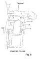
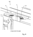
- FIG. 8 shows a sectional view of an upper portion of a door leaf 101 'of a two-lobular omnibus outer swing door according to the prior art, while FIG. 9 an associated perspective view shows.
- the door leaf 101 ' includes, as usual, a lifting device for raising and lowering the door leaf 101', a pivoting device for pivoting the door leaf 101 'and a guide linkage for ensuring correct alignment of the door leaf 101' (in FIGS FIGS. 8 and 9 Not shown).
- FIGS. 8 and 9 show a locking device 1 'with a cam 2' and a catch plate 3 '.
- the cam 1 ' is fixedly mounted on an upper door frame member, while the catch plate 3' is fixedly mounted on the door portal.
- the door leaf 101' is raised by means of the lifting device, whereupon the in the FIGS. 8 and 9 not visible lateral locking wedges laterally lock and the locking device 1 'locked above.
- this can lead to stresses in the door leaf 101 'due to tolerances and / or static over-determination.
- the escape between the door 101 'and the vehicle outer skin can be disturbed, z. B. the door 101 'top or protrude from the vehicle outer skin.
- An object of the invention is to provide an improved and / or alternative locking device for a door, useful for a two-winged vehicle door, by means of the particular tension or deformation due to static overdetermination and / or tolerances in the locked state can be reduced or avoided.
- the invention provides a locking device for locking a door leaf (for example a door leaf), preferably for a two-winged vehicle door, in particular a vehicle outer swinging door.
- a door leaf for example a door leaf
- a two-winged vehicle door in particular a vehicle outer swinging door.
- the locking device comprises a cam device and preferably a catching device.
- the catching device is preferably used for direct or indirect mounting on the door portal to be closed by the door leaf.
- the door portal is suitably firmly connected to the vehicle, in particular with a support frame of an omnibus.
- the cam device is expediently used for direct or indirect mounting on the door leaf.
- the cam device comprises at least one cam for locking with the catching device, in particular in an opening of the catching device.
- the cam device is characterized in particular by the fact that it comprises an adjusting, in particular adjusting device, by means of which the mooring position of the at least one cam can be variably adjusted.
- the cam device comprises at least two cams between which the adjusting device extends.
- the two cams are designed in particular as a cam pair.
- the adjusting device is preferably designed as a slot-screw construction.
- the cam means may comprise a mounting member for direct or indirect mounting to the door leaf.
- the at least one cam is expediently connected to the mounting element in such a way that its mooring position can be set variably relative to the mounting element.
- the at least one cam thus be moved relative to the mounting member to be fixed at a suitable mooring position.
- the at least one cam is preferably connected to the mounting element by means of a guide-groove-guide projection construction.
- the guide groove-guide projection construction is expedient for creating a predefined movement path of the at least one cam relative to the mounting element and / or for preventing a rotation of the at least one cam.
- the at least one cam is partially cut out in order to be able to dive into the catching device, in particular an opening of the catching device.
- the at least one cam is thereby preferably partially narrower and partially wider than the opening of the catching device.
- the mooring position of the at least one cam is adjustable transversely to the longitudinal extension of the mounting member and / or transversely to the door leaf level.
- the cam device and / or the mounting element is expediently used for indirect or direct mounting on an upper frame element of the door leaf.
- the upper frame element expediently extends in the longitudinal direction of the vehicle and / or in the width direction of the vehicle door.
- the door leaf preferably comprises a lifting device for lifting the door leaf (and thus expediently locking the locking device) and lowering the door leaf (and thus expediently unlocking the locking device).
- the door preferably comprises a pivoting device, for.
- a pivoting device for.
- the door can also be provided with a variable length guide rods.
- the guide linkage serves to ensure correct alignment between the door leaf and the vehicle outer skin, e.g. As a parallelism between the door in the open state and the vehicle skin and / or an escape between the door in the closed state and the vehicle outer skin to achieve.
- the invention is not limited to a locking device, but also includes a door leaf, preferably for a two-leaf vehicle door, in particular a vehicle exterior swing door.
- the door is equipped with a locking device as described herein.
- the invention also includes a vehicle, in particular a bus, with at least one door leaf and / or a locking device as described herein.
- the door leaf is preferably an omnibus door leaf and / or the vehicle door is preferably an omnibus door, preferably a omnibus outer swing door.
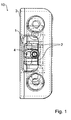
- FIG. 1 shows a perspective view of a locking device 10 according to an embodiment of the invention.
- the locking device 10 is for locking a, for example, in the FIGS. 6 and 7 shown door leaf 101 of a two-leaf vehicle door 100, preferably a bus-outside swing door.
- the locking device 10 comprises a cam device 1 for direct or indirect mounting to the door leaf 101 and a catching device 3 for mounting on the door portal, which is opened and closed by the door leaf 101.
- the cam device 1 includes a cam pair 2.
- the cam pair 2 is locked in an opening of the catcher 3 when the door leaf 101 is in the closed state and raised.
- the cam pair 2 is unlocked by the catcher 3 when the door leaf 101 is lowered to be opened thereafter.
- the cam device 1 is provided with an adjusting / adjusting device 4, by means of which the mooring position of the cam pair 2 can be variably adjusted.
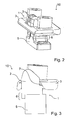
- FIG. 2 shows another perspective view of the locking device 10.
- the cam-ken Eis 1 comprises a mounting member 5 for mounting to the door leaf 101.
- the cam pair 2 is connected to the mounting member 5, that its mooring position relative to the mounting member 5 can be variably adjusted ,
- the cam pair 2 is connected to the mounting member 5 via a guide groove guide projection structure 6, whereby twisting or tilting of the cam pair 2 on the mounting member 5 can be prevented.
- FIG. 3 shows a perspective sectional view through the locking device 10.
- Figure 3 shows sometimes that the cam pair 2 has a recess 7 in order to be able to dive into an opening of the catcher 3 can.
- FIGS. 4 and 5 show various perspective views of the locking device 10, but without catching device 3.
- the adjusting device 4 is arranged between the cams 2 of the cam pair and designed as a slot-screw construction.
- the mooring position of the cam pair 2 is adjustable transversely to the longitudinal extension of the mounting member 5, which corresponds to a direction transverse to the plane of the door leaf 101.
- the reference character E indicates the setting direction in which the mooring position of the cam pair 2 can be adjusted.
- FIGS. 4 and 5 show the cam pair 2 in different mooring positions.
- the cam pair 2 is fixed in an inner mooring position (in FIG FIG. 4 Left). This causes the door 101 is pulled relatively far into the vehicle.
- the cam pair 2 is fixed in an outer mooring position (in FIG. 5 right). As a result, the door panel 101 is relatively slightly drawn into the vehicle.
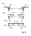
- FIG. 6 shows a two-lobular omnibus fashionschwenkte 100 with two door leaves 101 according to an embodiment of the invention, below in the closed state, in the middle in the partially opened state and at the top in the fully open state.
- the right door leaf 101 is provided with locking wedges on the right and with a locking device 10 on the top.
- the left door leaf 101 is provided on the left with locking wedges and at the top with a locking device 10 (see reference numerals 10 and 20 in FIG FIG. 7 ).
- the locking wedges and the locking devices 10 are in FIG. 6 not shown.
- the door leaves 101 further comprise a lifting device 102, by means of which they can be raised and lowered.
- the door leaves 101 further comprise a pivoting device 103, by means of which they can be swung out to open and pivoted to close.
- the door leaves 101 also include a variable length guide rod 104, which serves to ensure in particular a parallelism between the door leaves 101 in the open state on the one hand and the vehicle outer skin on the other.
- the door leaves 101 are lowered by means of the lifting devices 102, whereupon the lateral closing wedges and the cam devices 10 are unlocked. Im unlocked lowered state of the door leaves 101, the door leaves 101 by means of the pivoting devices 103 outwardly in the in FIG. 6 pivoted open state shown above.
- the door leaves 101 are pivoted by means of the pivoting means 103 inwardly and raised in the closed state by means of the lifting devices 102, whereupon the side closing wedges and the cam devices 10 lock.
- stresses and deformations which can be caused in particular by the lateral closing wedges and the cam devices 10 caused static overdetermination and / or tolerances can be avoided because the cam pairs 2 of the locking devices 10 are variably aligned.
- FIG. 7 shows a vehicle exterior swing gate 100 with two door leaves 101 and thus a two-leaf vehicle exterior swing door 100.
- the reference numerals 20 designate side, conveniently conventional locking wedges, while the reference numerals 10 designate cam devices according to the invention.
- FIG. 7 It can be seen that the cam device 10 is designed for mounting on an upper frame member of the door leaf 101.
Landscapes
- Engineering & Computer Science (AREA)
- Mechanical Engineering (AREA)
- Lock And Its Accessories (AREA)
- Body Structure For Vehicles (AREA)
Priority Applications (1)
| Application Number | Priority Date | Filing Date | Title |
|---|---|---|---|
| PL14002504T PL2853672T3 (pl) | 2013-09-13 | 2014-07-18 | Drzwi pojazdu z regulowanym urządzeniem krzywkowym |
Applications Claiming Priority (1)
| Application Number | Priority Date | Filing Date | Title |
|---|---|---|---|
| DE102013015221.6A DE102013015221A1 (de) | 2013-09-13 | 2013-09-13 | Fahrzeugtür mit einstellbarer Nockeneinrichtung |
Publications (2)
| Publication Number | Publication Date |
|---|---|
| EP2853672A1 true EP2853672A1 (fr) | 2015-04-01 |
| EP2853672B1 EP2853672B1 (fr) | 2018-01-03 |
Family
ID=51211495
Family Applications (1)
| Application Number | Title | Priority Date | Filing Date |
|---|---|---|---|
| EP14002504.0A Active EP2853672B1 (fr) | 2013-09-13 | 2014-07-18 | Porte de véhicule dotée d'un dispositif à came réglable |
Country Status (8)
| Country | Link |
|---|---|
| EP (1) | EP2853672B1 (fr) |
| CN (1) | CN104453503B (fr) |
| BR (1) | BR102014015869B1 (fr) |
| DE (1) | DE102013015221A1 (fr) |
| HU (1) | HUE036020T2 (fr) |
| PL (1) | PL2853672T3 (fr) |
| RU (1) | RU2671769C2 (fr) |
| TR (1) | TR201803014T4 (fr) |
Citations (2)
| Publication number | Priority date | Publication date | Assignee | Title |
|---|---|---|---|---|
| US4308691A (en) * | 1979-07-26 | 1982-01-05 | Firma Gebr. Bode & Co. | Apparatus for locking the leaf of a swing door |
| DE3148035A1 (de) * | 1981-12-04 | 1983-06-09 | Kiekert GmbH & Co KG, 5628 Heiligenhaus | Tueranlage fuer fahrzeuge, insbesondere omnibusfahrzeuge |
Family Cites Families (8)
| Publication number | Priority date | Publication date | Assignee | Title |
|---|---|---|---|---|
| FR572369A (fr) * | 1923-10-26 | 1924-06-04 | Accessoires Pour Automobiles E | Butées et gâche réglables pour portes et portières de voitures |
| DE1206739B (de) * | 1961-01-26 | 1965-12-09 | Kloeckner Humboldt Deutz Ag | Keilpaar zum Fuehren und Halten von Kraftfahrzeugtueren in der Schliessstellung |
| JPS59227572A (ja) * | 1983-06-08 | 1984-12-20 | Toyota Motor Corp | 自動車製造ラインにおける自動車ドア開閉装置 |
| US4539775A (en) * | 1984-04-06 | 1985-09-10 | General Motors Corporation | Locking mechanism for vehicle door |
| JP2003097124A (ja) * | 2001-09-27 | 2003-04-03 | Nabco Ltd | 車両用ドアのロック装置 |
| CN201212323Y (zh) * | 2008-06-26 | 2009-03-25 | 河北工业大学 | 一种双扇客车门电动内摆门机系统 |
| US8469413B2 (en) * | 2010-10-08 | 2013-06-25 | GM Global Technology Operations LLC | Adjustable striker for vehicle door latch |
| CN201856612U (zh) * | 2010-10-21 | 2011-06-08 | 上海申龙客车有限公司 | 公交车平移乘客门换型结构 |
-
2013
- 2013-09-13 DE DE102013015221.6A patent/DE102013015221A1/de not_active Withdrawn
-
2014
- 2014-06-26 BR BR102014015869-3A patent/BR102014015869B1/pt active IP Right Grant
- 2014-07-18 TR TR2018/03014T patent/TR201803014T4/tr unknown
- 2014-07-18 HU HUE14002504A patent/HUE036020T2/hu unknown
- 2014-07-18 EP EP14002504.0A patent/EP2853672B1/fr active Active
- 2014-07-18 PL PL14002504T patent/PL2853672T3/pl unknown
- 2014-07-21 RU RU2014130011A patent/RU2671769C2/ru active
- 2014-09-12 CN CN201410462943.6A patent/CN104453503B/zh active Active
Patent Citations (2)
| Publication number | Priority date | Publication date | Assignee | Title |
|---|---|---|---|---|
| US4308691A (en) * | 1979-07-26 | 1982-01-05 | Firma Gebr. Bode & Co. | Apparatus for locking the leaf of a swing door |
| DE3148035A1 (de) * | 1981-12-04 | 1983-06-09 | Kiekert GmbH & Co KG, 5628 Heiligenhaus | Tueranlage fuer fahrzeuge, insbesondere omnibusfahrzeuge |
Also Published As
| Publication number | Publication date |
|---|---|
| RU2671769C2 (ru) | 2018-11-06 |
| CN104453503B (zh) | 2018-07-10 |
| BR102014015869A2 (pt) | 2016-02-23 |
| EP2853672B1 (fr) | 2018-01-03 |
| DE102013015221A1 (de) | 2015-03-19 |
| BR102014015869B1 (pt) | 2021-07-13 |
| HUE036020T2 (hu) | 2018-06-28 |
| TR201803014T4 (tr) | 2018-03-21 |
| CN104453503A (zh) | 2015-03-25 |
| PL2853672T3 (pl) | 2018-06-29 |
| RU2014130011A (ru) | 2016-02-10 |
Similar Documents
| Publication | Publication Date | Title |
|---|---|---|
| EP3363976B1 (fr) | Dispositif de limitation d'ouverture rotative pour une fenêtre ou pour une porte permettant de limiter le mouvement d'ouverture rotatif d'un vantail d'une fenêtre ou d'une porte | |
| DE102013007191B3 (de) | Tür- oder Fenstersicherung sowie Türe oder Fenster mit einer Tür- oder Fenstersicherung | |
| EP1312743A2 (fr) | Dispositif de blocage pour un vantail coulissant et levant; ferrure du type crémone avec un tel dispositif; porte ou fenêtre coulissante et levante avec un tel dispositif | |
| DE102018121305A1 (de) | Flugzeugtür, Flugzeugbereich und Flugzeug mit einer Flugzeugtür | |
| EP2853672B1 (fr) | Porte de véhicule dotée d'un dispositif à came réglable | |
| DE2812894A1 (de) | Falzschere fuer kippfluegel von fenstern, tueren o.dgl. | |
| DE202008010055U1 (de) | Gebäudeabschluss in sprengwirkungshemmender und/oder einbruchhemmender Ausführung | |
| EP1614844A2 (fr) | Dispositif d'articulation | |
| EP3237708B1 (fr) | Ferrure destinée à être montée entre un battant et un cadre fixe d'une fenêtre, d'une porte ou similaire ainsi que fenêtre, porte ou similaire comprenant une ferrure de ce type | |
| DE102009056878A1 (de) | Tür für einen Kraftwagen | |
| DE102014221290B3 (de) | Verbindungsanordnung für ein Fenster, eine Tür oder dergleichen | |
| EP2733288B1 (fr) | Verrou à barre rotative, en particulier pour portes pivotantes de structures de véhicules automobiles | |
| DE935349C (de) | Verschluss- und Feststellvorrichtung von parallelzuruecksetzbaren und anschliessend schwenkbaren Fluegeln von Fenstern, Tueren od. dgl. mit einer Hubvorrichtung | |
| DE691762C (de) | Tuer fuer Fahrzeuge, insbesondere Kraftfahrzeuge | |
| DE1584084A1 (de) | Ausstellvorrichtung fuer Drehkippfenster | |
| DE1930485A1 (de) | Schwenkschiebetuer,insbesondere fuer Strassen- und Schienenfahrzeuge | |
| DE2932865A1 (de) | Beschlag fuer dachfenster | |
| EP1780362B1 (fr) | Entraînement pour vantaux pivotants | |
| DE19912077C2 (de) | Außentür für einen Wohnwagen, ein Wohnmobil oder dgl. | |
| AT519074B1 (de) | Verschlussvorrichtung für eine Bordwand | |
| CH666717A5 (de) | Schloss fuer eine schwenkbare tuere. | |
| DE102023104712A1 (de) | Schiebetür mit einem verriegelbaren Schiebeflügel und Verriegelungseinrichtung | |
| DE102008063734A1 (de) | Verriegelungseinrichtung | |
| DE2157549A1 (de) | Verschlußeinrichtung für Fensterflügel | |
| EP2765269B1 (fr) | Régulateur de séquence de fermeture pour une construction de porte à deux battants comprenant un battant fixe et un battant mobile |
Legal Events
| Date | Code | Title | Description |
|---|---|---|---|
| PUAI | Public reference made under article 153(3) epc to a published international application that has entered the european phase |
Free format text: ORIGINAL CODE: 0009012 |
|
| 17P | Request for examination filed |
Effective date: 20140718 |
|
| AK | Designated contracting states |
Kind code of ref document: A1 Designated state(s): AL AT BE BG CH CY CZ DE DK EE ES FI FR GB GR HR HU IE IS IT LI LT LU LV MC MK MT NL NO PL PT RO RS SE SI SK SM TR |
|
| AX | Request for extension of the european patent |
Extension state: BA ME |
|
| R17P | Request for examination filed (corrected) |
Effective date: 20150303 |
|
| 17Q | First examination report despatched |
Effective date: 20160930 |
|
| STAA | Information on the status of an ep patent application or granted ep patent |
Free format text: STATUS: EXAMINATION IS IN PROGRESS |
|
| GRAP | Despatch of communication of intention to grant a patent |
Free format text: ORIGINAL CODE: EPIDOSNIGR1 |
|
| STAA | Information on the status of an ep patent application or granted ep patent |
Free format text: STATUS: GRANT OF PATENT IS INTENDED |
|
| INTG | Intention to grant announced |
Effective date: 20170825 |
|
| GRAS | Grant fee paid |
Free format text: ORIGINAL CODE: EPIDOSNIGR3 |
|
| GRAA | (expected) grant |
Free format text: ORIGINAL CODE: 0009210 |
|
| STAA | Information on the status of an ep patent application or granted ep patent |
Free format text: STATUS: THE PATENT HAS BEEN GRANTED |
|
| AK | Designated contracting states |
Kind code of ref document: B1 Designated state(s): AL AT BE BG CH CY CZ DE DK EE ES FI FR GB GR HR HU IE IS IT LI LT LU LV MC MK MT NL NO PL PT RO RS SE SI SK SM TR |
|
| REG | Reference to a national code |
Ref country code: GB Ref legal event code: FG4D Free format text: NOT ENGLISH |
|
| REG | Reference to a national code |
Ref country code: CH Ref legal event code: EP Ref country code: AT Ref legal event code: REF Ref document number: 960435 Country of ref document: AT Kind code of ref document: T Effective date: 20180115 |
|
| REG | Reference to a national code |
Ref country code: NL Ref legal event code: FP Ref country code: IE Ref legal event code: FG4D Free format text: LANGUAGE OF EP DOCUMENT: GERMAN |
|
| REG | Reference to a national code |
Ref country code: DE Ref legal event code: R096 Ref document number: 502014006774 Country of ref document: DE |
|
| REG | Reference to a national code |
Ref country code: SE Ref legal event code: TRGR |
|
| REG | Reference to a national code |
Ref country code: LT Ref legal event code: MG4D |
|
| REG | Reference to a national code |
Ref country code: HU Ref legal event code: AG4A Ref document number: E036020 Country of ref document: HU |
|
| REG | Reference to a national code |
Ref country code: FR Ref legal event code: PLFP Year of fee payment: 5 |
|
| PG25 | Lapsed in a contracting state [announced via postgrant information from national office to epo] |
Ref country code: ES Free format text: LAPSE BECAUSE OF FAILURE TO SUBMIT A TRANSLATION OF THE DESCRIPTION OR TO PAY THE FEE WITHIN THE PRESCRIBED TIME-LIMIT Effective date: 20180103 Ref country code: NO Free format text: LAPSE BECAUSE OF FAILURE TO SUBMIT A TRANSLATION OF THE DESCRIPTION OR TO PAY THE FEE WITHIN THE PRESCRIBED TIME-LIMIT Effective date: 20180403 Ref country code: HR Free format text: LAPSE BECAUSE OF FAILURE TO SUBMIT A TRANSLATION OF THE DESCRIPTION OR TO PAY THE FEE WITHIN THE PRESCRIBED TIME-LIMIT Effective date: 20180103 Ref country code: FI Free format text: LAPSE BECAUSE OF FAILURE TO SUBMIT A TRANSLATION OF THE DESCRIPTION OR TO PAY THE FEE WITHIN THE PRESCRIBED TIME-LIMIT Effective date: 20180103 Ref country code: LT Free format text: LAPSE BECAUSE OF FAILURE TO SUBMIT A TRANSLATION OF THE DESCRIPTION OR TO PAY THE FEE WITHIN THE PRESCRIBED TIME-LIMIT Effective date: 20180103 Ref country code: CY Free format text: LAPSE BECAUSE OF FAILURE TO SUBMIT A TRANSLATION OF THE DESCRIPTION OR TO PAY THE FEE WITHIN THE PRESCRIBED TIME-LIMIT Effective date: 20180103 |
|
| PG25 | Lapsed in a contracting state [announced via postgrant information from national office to epo] |
Ref country code: IS Free format text: LAPSE BECAUSE OF FAILURE TO SUBMIT A TRANSLATION OF THE DESCRIPTION OR TO PAY THE FEE WITHIN THE PRESCRIBED TIME-LIMIT Effective date: 20180503 Ref country code: BG Free format text: LAPSE BECAUSE OF FAILURE TO SUBMIT A TRANSLATION OF THE DESCRIPTION OR TO PAY THE FEE WITHIN THE PRESCRIBED TIME-LIMIT Effective date: 20180403 Ref country code: LV Free format text: LAPSE BECAUSE OF FAILURE TO SUBMIT A TRANSLATION OF THE DESCRIPTION OR TO PAY THE FEE WITHIN THE PRESCRIBED TIME-LIMIT Effective date: 20180103 Ref country code: GR Free format text: LAPSE BECAUSE OF FAILURE TO SUBMIT A TRANSLATION OF THE DESCRIPTION OR TO PAY THE FEE WITHIN THE PRESCRIBED TIME-LIMIT Effective date: 20180404 Ref country code: RS Free format text: LAPSE BECAUSE OF FAILURE TO SUBMIT A TRANSLATION OF THE DESCRIPTION OR TO PAY THE FEE WITHIN THE PRESCRIBED TIME-LIMIT Effective date: 20180103 |
|
| PG25 | Lapsed in a contracting state [announced via postgrant information from national office to epo] |
Ref country code: MT Free format text: LAPSE BECAUSE OF FAILURE TO SUBMIT A TRANSLATION OF THE DESCRIPTION OR TO PAY THE FEE WITHIN THE PRESCRIBED TIME-LIMIT Effective date: 20180103 |
|
| REG | Reference to a national code |
Ref country code: DE Ref legal event code: R097 Ref document number: 502014006774 Country of ref document: DE |
|
| PG25 | Lapsed in a contracting state [announced via postgrant information from national office to epo] |
Ref country code: EE Free format text: LAPSE BECAUSE OF FAILURE TO SUBMIT A TRANSLATION OF THE DESCRIPTION OR TO PAY THE FEE WITHIN THE PRESCRIBED TIME-LIMIT Effective date: 20180103 Ref country code: AL Free format text: LAPSE BECAUSE OF FAILURE TO SUBMIT A TRANSLATION OF THE DESCRIPTION OR TO PAY THE FEE WITHIN THE PRESCRIBED TIME-LIMIT Effective date: 20180103 Ref country code: RO Free format text: LAPSE BECAUSE OF FAILURE TO SUBMIT A TRANSLATION OF THE DESCRIPTION OR TO PAY THE FEE WITHIN THE PRESCRIBED TIME-LIMIT Effective date: 20180103 |
|
| PLBE | No opposition filed within time limit |
Free format text: ORIGINAL CODE: 0009261 |
|
| STAA | Information on the status of an ep patent application or granted ep patent |
Free format text: STATUS: NO OPPOSITION FILED WITHIN TIME LIMIT |
|
| PG25 | Lapsed in a contracting state [announced via postgrant information from national office to epo] |
Ref country code: CZ Free format text: LAPSE BECAUSE OF FAILURE TO SUBMIT A TRANSLATION OF THE DESCRIPTION OR TO PAY THE FEE WITHIN THE PRESCRIBED TIME-LIMIT Effective date: 20180103 Ref country code: SK Free format text: LAPSE BECAUSE OF FAILURE TO SUBMIT A TRANSLATION OF THE DESCRIPTION OR TO PAY THE FEE WITHIN THE PRESCRIBED TIME-LIMIT Effective date: 20180103 Ref country code: SM Free format text: LAPSE BECAUSE OF FAILURE TO SUBMIT A TRANSLATION OF THE DESCRIPTION OR TO PAY THE FEE WITHIN THE PRESCRIBED TIME-LIMIT Effective date: 20180103 Ref country code: DK Free format text: LAPSE BECAUSE OF FAILURE TO SUBMIT A TRANSLATION OF THE DESCRIPTION OR TO PAY THE FEE WITHIN THE PRESCRIBED TIME-LIMIT Effective date: 20180103 |
|
| 26N | No opposition filed |
Effective date: 20181005 |
|
| PG25 | Lapsed in a contracting state [announced via postgrant information from national office to epo] |
Ref country code: SI Free format text: LAPSE BECAUSE OF FAILURE TO SUBMIT A TRANSLATION OF THE DESCRIPTION OR TO PAY THE FEE WITHIN THE PRESCRIBED TIME-LIMIT Effective date: 20180103 |
|
| REG | Reference to a national code |
Ref country code: CH Ref legal event code: PL |
|
| GBPC | Gb: european patent ceased through non-payment of renewal fee |
Effective date: 20180718 |
|
| PG25 | Lapsed in a contracting state [announced via postgrant information from national office to epo] |
Ref country code: LU Free format text: LAPSE BECAUSE OF NON-PAYMENT OF DUE FEES Effective date: 20180718 Ref country code: MC Free format text: LAPSE BECAUSE OF FAILURE TO SUBMIT A TRANSLATION OF THE DESCRIPTION OR TO PAY THE FEE WITHIN THE PRESCRIBED TIME-LIMIT Effective date: 20180103 |
|
| REG | Reference to a national code |
Ref country code: BE Ref legal event code: MM Effective date: 20180731 |
|
| REG | Reference to a national code |
Ref country code: IE Ref legal event code: MM4A |
|
| PG25 | Lapsed in a contracting state [announced via postgrant information from national office to epo] |
Ref country code: LI Free format text: LAPSE BECAUSE OF NON-PAYMENT OF DUE FEES Effective date: 20180731 Ref country code: IE Free format text: LAPSE BECAUSE OF NON-PAYMENT OF DUE FEES Effective date: 20180718 Ref country code: GB Free format text: LAPSE BECAUSE OF NON-PAYMENT OF DUE FEES Effective date: 20180718 Ref country code: CH Free format text: LAPSE BECAUSE OF NON-PAYMENT OF DUE FEES Effective date: 20180731 |
|
| PG25 | Lapsed in a contracting state [announced via postgrant information from national office to epo] |
Ref country code: BE Free format text: LAPSE BECAUSE OF NON-PAYMENT OF DUE FEES Effective date: 20180731 |
|
| REG | Reference to a national code |
Ref country code: DE Ref legal event code: R081 Ref document number: 502014006774 Country of ref document: DE Owner name: MAN TRUCK & BUS SE, DE Free format text: FORMER OWNER: MAN TRUCK & BUS AG, 80995 MUENCHEN, DE |
|
| PG25 | Lapsed in a contracting state [announced via postgrant information from national office to epo] |
Ref country code: PT Free format text: LAPSE BECAUSE OF FAILURE TO SUBMIT A TRANSLATION OF THE DESCRIPTION OR TO PAY THE FEE WITHIN THE PRESCRIBED TIME-LIMIT Effective date: 20180103 |
|
| PG25 | Lapsed in a contracting state [announced via postgrant information from national office to epo] |
Ref country code: MK Free format text: LAPSE BECAUSE OF NON-PAYMENT OF DUE FEES Effective date: 20180103 |
|
| REG | Reference to a national code |
Ref country code: AT Ref legal event code: MM01 Ref document number: 960435 Country of ref document: AT Kind code of ref document: T Effective date: 20190718 |
|
| PG25 | Lapsed in a contracting state [announced via postgrant information from national office to epo] |
Ref country code: AT Free format text: LAPSE BECAUSE OF NON-PAYMENT OF DUE FEES Effective date: 20190718 |
|
| PGFP | Annual fee paid to national office [announced via postgrant information from national office to epo] |
Ref country code: HU Payment date: 20250722 Year of fee payment: 12 |
|
| PGFP | Annual fee paid to national office [announced via postgrant information from national office to epo] |
Ref country code: NL Payment date: 20250724 Year of fee payment: 12 |
|
| PGFP | Annual fee paid to national office [announced via postgrant information from national office to epo] |
Ref country code: DE Payment date: 20250728 Year of fee payment: 12 |
|
| PGFP | Annual fee paid to national office [announced via postgrant information from national office to epo] |
Ref country code: PL Payment date: 20250708 Year of fee payment: 12 Ref country code: TR Payment date: 20250708 Year of fee payment: 12 Ref country code: IT Payment date: 20250721 Year of fee payment: 12 |
|
| PGFP | Annual fee paid to national office [announced via postgrant information from national office to epo] |
Ref country code: FR Payment date: 20250725 Year of fee payment: 12 |
|
| PGFP | Annual fee paid to national office [announced via postgrant information from national office to epo] |
Ref country code: SE Payment date: 20250725 Year of fee payment: 12 |