EP2853694A2 - Turbine à vapeur - Google Patents
Turbine à vapeur Download PDFInfo
- Publication number
- EP2853694A2 EP2853694A2 EP14181598.5A EP14181598A EP2853694A2 EP 2853694 A2 EP2853694 A2 EP 2853694A2 EP 14181598 A EP14181598 A EP 14181598A EP 2853694 A2 EP2853694 A2 EP 2853694A2
- Authority
- EP
- European Patent Office
- Prior art keywords
- turbine
- steam
- rotor
- inclination angle
- axial direction
- Prior art date
- Legal status (The legal status is an assumption and is not a legal conclusion. Google has not performed a legal analysis and makes no representation as to the accuracy of the status listed.)
- Granted
Links
Images


Classifications
-
- F—MECHANICAL ENGINEERING; LIGHTING; HEATING; WEAPONS; BLASTING
- F01—MACHINES OR ENGINES IN GENERAL; ENGINE PLANTS IN GENERAL; STEAM ENGINES
- F01D—NON-POSITIVE DISPLACEMENT MACHINES OR ENGINES, e.g. STEAM TURBINES
- F01D1/00—Non-positive-displacement machines or engines, e.g. steam turbines
- F01D1/02—Non-positive-displacement machines or engines, e.g. steam turbines with stationary working-fluid guiding means and bladed or like rotor, e.g. multi-bladed impulse steam turbines
- F01D1/04—Non-positive-displacement machines or engines, e.g. steam turbines with stationary working-fluid guiding means and bladed or like rotor, e.g. multi-bladed impulse steam turbines traversed by the working-fluid substantially axially
-
- F—MECHANICAL ENGINEERING; LIGHTING; HEATING; WEAPONS; BLASTING
- F01—MACHINES OR ENGINES IN GENERAL; ENGINE PLANTS IN GENERAL; STEAM ENGINES
- F01D—NON-POSITIVE DISPLACEMENT MACHINES OR ENGINES, e.g. STEAM TURBINES
- F01D25/00—Component parts, details, or accessories, not provided for in, or of interest apart from, other groups
- F01D25/24—Casings; Casing parts, e.g. diaphragms, casing fastenings
- F01D25/246—Fastening of diaphragms or stator-rings
-
- F—MECHANICAL ENGINEERING; LIGHTING; HEATING; WEAPONS; BLASTING
- F01—MACHINES OR ENGINES IN GENERAL; ENGINE PLANTS IN GENERAL; STEAM ENGINES
- F01D—NON-POSITIVE DISPLACEMENT MACHINES OR ENGINES, e.g. STEAM TURBINES
- F01D25/00—Component parts, details, or accessories, not provided for in, or of interest apart from, other groups
- F01D25/30—Exhaust heads, chambers, or the like
-
- F—MECHANICAL ENGINEERING; LIGHTING; HEATING; WEAPONS; BLASTING
- F05—INDEXING SCHEMES RELATING TO ENGINES OR PUMPS IN VARIOUS SUBCLASSES OF CLASSES F01-F04
- F05D—INDEXING SCHEME FOR ASPECTS RELATING TO NON-POSITIVE-DISPLACEMENT MACHINES OR ENGINES, GAS-TURBINES OR JET-PROPULSION PLANTS
- F05D2220/00—Application
- F05D2220/30—Application in turbines
- F05D2220/31—Application in turbines in steam turbines
Definitions
- Embodiments described herein relate generally to a steam turbine.
- Improvement in thermal efficiency of a steam turbine used in a thermal power station and the like has become an important task leading to efficient use of energy resources and a reduction in carbon dioxide (CO 2 ) emission. Effectively converting given energy to mechanical work makes it possible to achieve the improvement in thermal efficiency of a steam turbine. To achieve this, reducing various internal losses is required.
- the internal losses of the steam turbine include a profile loss resulting from a blade shape, turbine cascade losses based on a secondary flow loss of steam, a leakage loss of steam, a moisture loss of steam, and so on, passage part losses in passages other than a cascade represented by a steam valve and a crossover pipe, turbine exhaust losses resulting from a turbine exhaust chamber, and so on.
- the turbine exhaust loss is a large loss occupying 10% to 20% of all of the internal losses.
- the turbine exhaust loss is a loss generated from an outlet of a final stage of turbine stages to an inlet of a condenser.
- the turbine exhaust losses are further classified into a leaving loss, a hood loss, an annular area restriction loss, a turn-up loss, and so on.
- the hood loss is a pressure loss from an exhaust chamber to a condenser.
- the hood loss depends on a type, a shape, and a size of the exhaust chamber including a diffuser.
- the pressure loss increases in proportion to the square of a flow velocity of the steam. Therefore, it is effective to reduce the flow velocity of the steam by increasing the size of the exhaust chamber in an allowable range.
- the increase in the size of the exhaust chamber is restricted by manufacturing cost, arrangement space of a building, and so on.
- the hood loss depends on an axial velocity being a velocity in a turbine rotor axial direction, in other words, a volume flow rate passing through the exhaust chamber.
- the hood loss depends on a design of the exhaust chamber including the diffuser.
- An exhaust chamber of a low-pressure turbine occupies a large capacity in a whole of the steam turbine. Accordingly, the increase in the size of the exhaust chamber to reduce the hood loss largely affects on a whole size and the manufacturing cost of the steam turbine. Therefore, it is important to enable a shape whose pressure loss is small within the limited size of the exhaust chamber.
- a double-flow exhaust type (double flow type) low-pressure turbine including a conventional exhaust chamber in a downward exhaust type
- steam passing through a rotor blade of a final turbine stage is led to an annular diffuser made up of a steam guide and a bearing cone.
- the steam led to the diffuser flows out radially toward outside in a radial direction.
- a flow of the steam flowing out radially is turned by a casing and so on, and the steam is led to the condenser provided at downward of the steam turbine.
- the low-pressure turbine As stated above, it is important to decelerate the flow at the annular diffuser and to enough recover a static pressure to reduce the pressure loss (static pressure loss) in the exhaust chamber.
- the steam separates at a position near an inlet in the diffuser. The separation as stated above remarkably occurs when the flow of the steam cannot be turned moderately in the diffuser, specifically, when a distance of the bearing cone in the turbine rotor axial direction is short.
- a steam turbine includes: a turbine rotor, rotor blade cascades each made up by implanting plural rotor blades to the turbine rotor in a circumferential direction; an inner casing where the turbine rotor including the rotor blade cascades is provided to penetrate; an outer casing surrounding the inner casing; and stationary blade cascades each made up by attaching plural stationary blades between diaphragm outer rings and diaphragm inner rings provided at an inner side of the inner casing in a circumferential direction, and disposed alternately with the rotor blade cascades in a turbine rotor axial direction.
- the steam turbine includes an annular diffuser provided at a downstream side of a final turbine stage from among turbine stages each made up of the stationary blade cascade and the rotor blade cascade at immediate downstream of the stationary blade cascade, formed by a steam guide and a bearing cone at an inner side of the steam guide, and discharging steam passing through the final turbine stage toward outside in a radial direction.
- An enlarged inclination angle ⁇ 1 of an inner surface of the diaphragm outer ring where an outer periphery of the stationary blade of the final turbine stage is attached relative to the turbine rotor axial direction is an enlarged inclination angle ⁇ 2 of an inner surface at an inlet of the steam guide relative to the turbine rotor axial direction or more.
- FIG. 1 is a view illustrating a meridian cross section in a vertical direction of a steam turbine 10 according to an embodiment.
- a double-flow exhaust type low-pressure turbine including an exhaust chamber in a downward exhaust type is exemplified to be explained as the steam turbine 10.
- an inner casing 21 is included in an outer casing 20.
- a turbine rotor 22 is provided to penetrate in the inner casing 21.
- rotor disks 23 protruding toward outside in a radial direction are formed along a circumferential direction.
- the rotor disks 23 are formed in plural stages in a turbine rotor axial direction.
- Plural rotor blades 24 are implanted to the rotor disk 23 of the turbine rotor 22 in the circumferential direction to make up a rotor blade cascade.
- the rotor blade cascades are included in plural stages in the turbine rotor axial direction.
- the turbine rotor 22 is rotatably supported by a rotor bearing 25.
- Diaphragm outer rings 26 and diaphragm inner rings 27 are provided at an inner side of the inner casing 21.
- Plural stationary blades 28 are arranged in the circumferential direction between the diaphragm outer ring 26 and the diaphragm inner ring 27 to make up a stationary blade cascade.
- the stationary blade cascades are disposed alternately with the rotor blade cascades in the turbine rotor axial direction.
- the stationary blade cascade and the rotor blade cascade at immediate downstream of the stationary blade cascade make up a turbine stage.
- An intake chamber 30 where steam from a crossover pipe 29 is led is included at a center of the steam turbine 10. The steam is distributed and led to the left and right turbine stages from this intake chamber 30.
- annular diffuser 60 is formed by a steam guide 40 at an outer peripheral side and a bearing cone 50 at an inner peripheral side thereof.
- the annular diffuser 60 discharges the steam toward outside in the radial direction.
- the rotor bearing 25 and so on are included at an inner side of the bearing cone 50.
- a condenser (not-illustrated) is included at downward of the exhaust chamber in the downward exhaust type including the annular diffuser 60.
- the above-stated outer caging 20, the inner casing 21, the steam guide 40, the bearing cone 50, and so on are made up with a structure divided into half at above and below.
- the cylindrical steam guide 40 is made up by an upper half side and lower half side steam guides 40.
- the cylindrical bearing cone 50 is made up by an upper half side and lower half side bearing cones 50.
- the annular diffuser 60 is made up by the cylindrical steam guide 40 and the cylindrical bearing cone 50 provided at an inner side thereof. Note that constitutions of the upper half side and lower half side in the steam guide 40 and the bearing cone 50 are the same.
- FIG. 2 is a view enlarging a meridian cross section in a vertical direction of the final turbine stage and the annular diffuser 60 at the steam turbine 10 according to the embodiment. Note that in FIG. 2 , components of the final turbine stage are represented by adding "a" to each of reference numerals of components illustrated in FIG. 1 for convenience to explain.
- a stationary blade 28a of the final turbine stage is attached between a diaphragm outer ring 26a and a diaphragm inner ring 27a.
- An inner surface 70 of the diaphragm outer ring 26a where an outer periphery of the stationary blade 28a is attached expands, for example, linearly toward outside in the radial direction as it goes toward a downstream side in the turbine rotor axial direction.
- the inner surface 70 inclines at an enlarged inclination angle ⁇ 1 relative to the turbine rotor axial direction toward outside in the radial direction as it goes toward the downstream side (right direction in FIG. 2 ) in the turbine rotor axial direction.
- a shroud 75 is included at a tip part of a rotor blade 24a at downstream of the stationary blade 28a.
- the shroud 75 is included at the tip part of the rotor blade 24a, and thereby, it is possible to suppress instability of flow resulting from vibration at the tip.
- An inner surface 110 of the diaphragm outer ring 26a at a periphery of the rotor blade 24a is, for example, approximately horizontal in the turbine rotor axial direction as illustrated in FIG. 2 .
- the tip part of the rotor blade 24a namely, the shroud 75 is made up to be, for example, approximately horizontal at a cross section illustrated in FIG. 2 so as to keep a distance with the inner surface 110 of the diaphragm outer ring 26a constant.
- the tip part of the rotor blade 24a is made to be approximately horizontal in the turbine rotor axial direction along the inner surface 110, and thereby, for example, it is possible to suppress an increase of a leakage steam amount from between the tip part of the rotor blade 24a and the inner surface 110 even when a thermal expansion of the turbine rotor 22 in the turbine rotor axial direction occurs. It is thereby possible to stabilize the flow of the steam flowing out of the rotor blade 24a and to lead the steam to the annular diffuser 60.
- the shroud 75 is included at the tip part of the rotor blade 24a , but it may be a constitution in which the shroud 75 is not included at the tip part of the rotor blade 24a.
- the tip of the rotor blade 24a is made up to be, for example, approximately horizontal at the cross section illustrated in FIG. 2 .
- the annular diffuser 60 formed by the steam guide 40 and the bearing cone 50 is formed at the downstream side of the final turbine stage.
- the bearing cone 50 is made up to be an enlarged cylindrical state widening toward outside in the radial direction as it goes toward the downstream side in the turbine rotor axial direction.
- An upstream end of the bearing cone 50 is adjacent to an outer part in the radial direction from among a downstream side end face of the rotor disk 23a to a degree not to be in contact with the rotating rotor disk 23a as illustrated in FIG. 2 .
- a downstream end of the bearing cone 50 is in contact with an inner wall surface 91 of a sidewall 90 of the outer casing 20 at the downstream side in the turbine rotor axial direction.
- the bearing cone 50 expands while bending as it goes toward the downstream side in the turbine rotor axial direction.
- the bearing cone 50 may be a constitution including, for example, a part expanding linearly and a part expanding while bending toward outside in the radial direction as it goes toward the downstream side in the turbine rotor axial direction.
- the bearing cone 50 may be a constitution including, for example, plural parts expanding linearly toward outside in the radial direction as it goes toward the downstream side in the turbine rotor axial direction.
- the steam guide 40 is constituted to be the enlarged cylindrical state widening toward outside in the radial direction as it goes toward the downstream side in the turbine rotor axial direction.
- An upstream end of the steam guide 40 is in contact with an inside part in the radial direction from among the downstream side end face of the diaphragm outer ring 26a as illustrated in FIG. 2 .
- An upstream part of the steam guide 40 expands, for example, linearly toward outside in the radial direction as it goes toward the downstream side in the turbine rotor axial direction, and a downstream part expands while bending toward outside in the radial direction as it goes toward the downstream side in the turbine rotor axial direction.
- a shape of the steam guide 40 is not limited thereto.
- the steam guide 40 may be constituted to be a bugle state expanding while bending toward outside in the radial direction as it goes toward the downstream side in the turbine rotor axial direction from, for example, the upstream end to a downstream end.
- An inner surface 80 at an inlet of the steam guide 40 inclines at an enlarged inclination angle ⁇ 2 relative to the turbine rotor axial direction toward outside in the radial direction as it goes toward the downstream side in the turbine rotor axial direction as illustrated in FIG. 2 .
- the enlarged inclination angle ⁇ 2 is defined by an angle made up of a tangent at an upstream end of the inner surface 80 of the steam guide 40 and the turbine rotor axial direction at the cross section illustrated in FIG. 2 .
- the enlarged inclination angle ⁇ 1 is preferably to be the enlarged inclination angle ⁇ 2 or more.
- the enlarged inclination angles ⁇ 1, ⁇ 2 are set as stated above, and thereby, the steam flowing out of the final turbine stage flows along the inner surface 80 at the inlet of the steam guide 40. It is thereby possible to prevent a separation of the flow generated at the inner surface 80 of the steam guide 40. In addition, it is possible to suppress reduction in a diffuser performance at the annular diffuser 60.
- a distance from a most downstream end 100 at a root of the rotor blade 24a to the inner wall surface 91 of the sidewall 90 where the downstream end of the bearing cone 50 is in contact is set to be L, and an outer diameter of the rotor blade 24a is set to be D.
- the outer diameter D is equal to a diameter of a circle drawn by a blade tip of the rotor blade 24a when the rotor blade 24a rotates.
- the outer diameter D is an outer diameter including the shroud 75 as illustrated in FIG. 1 and FIG. 2 .
- L/D is preferably set to be 0.2 or more and 0.6 or less.
- a separation loss a pressure loss resulting from the separation of the flow (hereinafter, referred to as a separation loss) generating at the inner surface 80 of the steam guide 40 occurs when "the enlarged inclination angle ⁇ 1 - the enlarged inclination angle ⁇ 2" is "0" (zero) degree or more.
- L/D exceeds 0.6, a size of the exhaust chamber increases.
- the enlarged inclination angles ⁇ 1, ⁇ 2 are set to satisfy the above-stated expression (1) in accordance with (L/D), and thereby, it is possible to prevent the separation loss and the bending loss. It is thereby possible to suppress the reduction in the diffuser performance at the annular diffuser 60.
- the steam flowing into the intake chamber 30 in the steam turbine 10 via the crossover pipe 29 branches and flows to the left and right turbine stages.
- the steam passes through a steam flow passage including the stationary blades 28 and the rotor blades 24 of each turbine stage while performing expansion work to rotate the turbine rotor 22.
- the steam passing through the final turbine stage flows into the annular diffuser 60.
- the steam flowing along the inner surface 70 of the diaphragm outer ring 26a also flows at an inlet of the annular diffuser 60 with the enlarged inclination angle ⁇ 1 of the inner surface 70. Accordingly, when the steam passing through the final turbine stage flows into the annular diffuser 60, the steam flows along the inner surface 80 of the steam guide 40 without being separated. The flow is decelerated by the annular diffuser 60.
- the steam flows out toward outside in the radial direction.
- the flow of the steam flowing toward outside in the radial direction is turned toward downward.
- the turned steam is led to, for example, a condenser (not-illustrated) provided at downward of the turbine rotor 22.
- the condenser (not-illustrated) is provided at downward of the turbine rotor 22 is illustrated, but the condenser may be included at, for example, a lateral side of the steam turbine 10 in a vertical and horizontal direction of the turbine rotor axial direction.
- the steam turbine 10 may be one in a lateral exhaust type without being limited to the downward exhaust type.
- the enlarged inclination angles ⁇ 1, ⁇ 2 are set in accordance with the ratio (L/D) between the distance L and the outer diameter D of the rotor blade 24a, and thereby, it is possible to suppress the separation loss and the bending loss at the annular diffuser 60 of the exhaust chamber. It is thereby possible to reduce the pressure loss at the exhaust chamber.
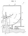
- FIG. 3 is a view enlarging a meridian cross section in a vertical direction of the final turbine stage and the annular diffuser 60 having another configuration at the steam turbine 10 according to the embodiment. Note that in FIG. 3 , components of the final turbine stage are represented by adding "a" to each of reference numerals of components illustrated in FIG. 1 for convenience to explain.
- the inner surface 110 of the diaphragm outer ring 26a at the periphery of the rotor blade 24a at the final turbine stage may be constituted to expand, for example, linearly toward outside in the radial direction as it goes toward the downstream side in the turbine rotor axial direction.
- the inner surface 110 inclines at an enlarged inclination angle ⁇ 3 relative to the turbine rotor axial direction toward outside in the radial direction as it goes toward the downstream side (right direction in FIG. 3 ) in the turbine rotor axial direction.
- the shroud 75 is, for example, provided to incline at the enlarged inclination angle ⁇ 3 relative to the turbine rotor axial direction toward outside in the radial direction as it goes toward the downstream side in the turbine rotor axial direction as illustrated in FIG. 3 .
- the outer diameter D of the rotor blade 24a is equal to a diameter of a circle drawn by a most tip part 75a of the shroud 75 in the radial direction when the rotor blade 24a rotates as illustrated in FIG. 3 .
- the most tip part 75a of the shroud 75 in the radial direction is an end part at outside in the radial direction of the shroud 75 at a most downstream side.
- the enlarged inclination angle ⁇ 3 satisfies a relationship of a following expression (2) without depending on the ratio (L/D) between the distance L and the outer diameter D of the rotor blade 24a.
- a unit of the above-stated relational expression is a degree.
- the enlarged inclination angle ⁇ 3 is set to be within this range, and thereby, the steam flowing along the inner surface 70 of the diaphragm outer ring 26a flows with the enlarged inclination angle ⁇ 1 of the inner surface 70 after passing through the inner surface 110.
- the steam flowing along the inner surface 70 of the diaphragm outer ring 26a flows with the enlarged inclination angle ⁇ 1 of the inner surface 70 also at the inlet of the annular diffuser 60. Accordingly, when the steam passing through the final turbine stage flows into the annular diffuser 60, the steam flows along the inner surface 80 of the steam guide 40 without being separated. The flow is decelerated by the annular diffuser 60. It is thereby possible to obtain an operation and effect similar to the operation and effect in the constitution illustrated in FIG. 2 .
- the double-flow exhaust type low-pressure turbine including the exhaust chamber in the downward exhaust type is exemplified to be described as the steam turbine 10, but the present embodiment is able to apply for, for example, a single-flow type low-pressure turbine..
- the constitution illustrated in FIG. 2 is used as a model of the steam turbine to be evaluated. Namely, the inner surface 110 of the diaphragm outer ring 26a at the periphery of the rotor blade 24a is made to be horizontal relative to the turbine rotor axial direction as illustrated in FIG. 2 .
- FIG. 4 is a view illustrating a result in which areas where the separation loss, the bending loss occur are found from the relationship between (L/D) and " ⁇ 1 - ⁇ 2". Note that FIG. 4 is a result found by a numerical analysis.
- a line L is a line in which angles of " ⁇ 1 - ⁇ 2" at a boundary where the bending loss does not occur when " ⁇ 1 - ⁇ 2" is changed under plural different (L/D) conditions are plotted and approximated.
- the bending loss occurs at upward of this line, namely, under a condition in which " ⁇ 1 - ⁇ 2" is larger than the line. In other words, at an area on the line and at downward of the line, the bending loss does not occur.
- a line M is a line in which angles of " ⁇ 1 - ⁇ 2" at a boundary where the separation loss does not occur when " ⁇ 1 - ⁇ 2" is changed under plural different (L/D) conditions are plotted and approximated.
- the separation loss occurs at downward of this line, namely, under a condition in which " ⁇ 1 - ⁇ 2" is smaller than the line. In other words, at an area on the line and at upward of the line, the separation loss does not occur.
- the range of (L/D) is set to be 0.2 or more and 0.6 or less as stated above, and the conditions in which the separation loss and the bending loss occur are evaluated within the range.
- an area where both the separation loss and the bending loss do not occur is represented by oblique lines.
- the separation loss and the bending loss do not occur, and therefore, it is possible to constitute the annular diffuser 60 having excellent diffuser performance.
Landscapes
- Engineering & Computer Science (AREA)
- Mechanical Engineering (AREA)
- General Engineering & Computer Science (AREA)
- Turbine Rotor Nozzle Sealing (AREA)
Applications Claiming Priority (2)
| Application Number | Priority Date | Filing Date | Title |
|---|---|---|---|
| JP2013176728 | 2013-08-28 | ||
| JP2014105128A JP6334258B2 (ja) | 2013-08-28 | 2014-05-21 | 蒸気タービン |
Publications (3)
| Publication Number | Publication Date |
|---|---|
| EP2853694A2 true EP2853694A2 (fr) | 2015-04-01 |
| EP2853694A3 EP2853694A3 (fr) | 2015-04-22 |
| EP2853694B1 EP2853694B1 (fr) | 2019-02-06 |
Family
ID=51389967
Family Applications (1)
| Application Number | Title | Priority Date | Filing Date |
|---|---|---|---|
| EP14181598.5A Active EP2853694B1 (fr) | 2013-08-28 | 2014-08-20 | Turbine à vapeur |
Country Status (3)
| Country | Link |
|---|---|
| US (1) | US9581026B2 (fr) |
| EP (1) | EP2853694B1 (fr) |
| JP (1) | JP6334258B2 (fr) |
Cited By (1)
| Publication number | Priority date | Publication date | Assignee | Title |
|---|---|---|---|---|
| EP3106615A1 (fr) * | 2015-06-18 | 2016-12-21 | Mitsubishi Hitachi Power Systems, Ltd. | Turbine axiale |
Families Citing this family (8)
| Publication number | Priority date | Publication date | Assignee | Title |
|---|---|---|---|---|
| US9598981B2 (en) * | 2013-11-22 | 2017-03-21 | Siemens Energy, Inc. | Industrial gas turbine exhaust system diffuser inlet lip |
| JP6628611B2 (ja) * | 2016-01-12 | 2020-01-15 | 三菱日立パワーシステムズ株式会社 | 蒸気タービン排気装置のフローガイド及び蒸気タービンの排気装置 |
| JP6731359B2 (ja) * | 2017-02-14 | 2020-07-29 | 三菱日立パワーシステムズ株式会社 | 排気ケーシング、及びこれを備える蒸気タービン |
| CN107131015A (zh) * | 2017-05-18 | 2017-09-05 | 东方电气集团东方汽轮机有限公司 | 一种汽轮机低压排汽缸导流环 |
| JP6944871B2 (ja) * | 2017-12-28 | 2021-10-06 | 三菱パワー株式会社 | 排気室及び蒸気タービン |
| CN108952821B (zh) * | 2018-09-25 | 2023-12-08 | 中国船舶重工集团公司第七0三研究所 | 一种固定船用汽轮机导流板结构 |
| JP2021001573A (ja) * | 2019-06-21 | 2021-01-07 | 株式会社東芝 | 蒸気タービン |
| JP7458947B2 (ja) * | 2020-09-15 | 2024-04-01 | 三菱重工コンプレッサ株式会社 | 蒸気タービン |
Family Cites Families (13)
| Publication number | Priority date | Publication date | Assignee | Title |
|---|---|---|---|---|
| AT383396B (de) | 1984-08-17 | 1987-06-25 | Proizv Ob Turbostroenia | Niederdruckzylinder einer dampfturbine |
| JPS62174507A (ja) * | 1986-01-27 | 1987-07-31 | Toshiba Corp | 軸流タ−ボ機械の排気デイフユ−ザ |
| JP3774321B2 (ja) * | 1998-04-24 | 2006-05-10 | 株式会社東芝 | 蒸気タービン |
| US6261055B1 (en) * | 1999-08-03 | 2001-07-17 | Jerzy A. Owczarek | Exhaust flow diffuser for a steam turbine |
| JP2005023809A (ja) * | 2003-06-30 | 2005-01-27 | Toshiba Corp | 蒸気タービン |
| JP4627217B2 (ja) * | 2005-05-30 | 2011-02-09 | 株式会社日立製作所 | タービン排気装置 |
| US7780403B2 (en) * | 2006-09-08 | 2010-08-24 | Siemens Energy, Inc. | Adjustable turbine exhaust flow guide and bearing cone assemblies |
| JP2010216321A (ja) | 2009-03-16 | 2010-09-30 | Hitachi Ltd | 蒸気タービンの動翼及びそれを用いた蒸気タービン |
| JP5812567B2 (ja) * | 2010-02-16 | 2015-11-17 | 三菱日立パワーシステムズ株式会社 | タービン |
| US20120163969A1 (en) * | 2010-12-23 | 2012-06-28 | General Electric Company | Turbine including exhaust hood |
| JP5606373B2 (ja) * | 2011-03-28 | 2014-10-15 | 株式会社東芝 | 蒸気タービン |
| KR20120124030A (ko) | 2011-05-02 | 2012-11-12 | 가부시끼가이샤 도시바 | 풍력 발전 시스템 및 그 제어 방법 |
| KR20140025716A (ko) | 2012-08-22 | 2014-03-05 | 현대중공업 주식회사 | 풍력발전기 제어 시스템 |
-
2014
- 2014-05-21 JP JP2014105128A patent/JP6334258B2/ja active Active
- 2014-08-19 US US14/462,856 patent/US9581026B2/en active Active
- 2014-08-20 EP EP14181598.5A patent/EP2853694B1/fr active Active
Non-Patent Citations (1)
| Title |
|---|
| None |
Cited By (4)
| Publication number | Priority date | Publication date | Assignee | Title |
|---|---|---|---|---|
| EP3106615A1 (fr) * | 2015-06-18 | 2016-12-21 | Mitsubishi Hitachi Power Systems, Ltd. | Turbine axiale |
| CN106256994A (zh) * | 2015-06-18 | 2016-12-28 | 三菱日立电力系统株式会社 | 轴流涡轮机 |
| US10301970B2 (en) | 2015-06-18 | 2019-05-28 | Mitsubishi Hitachi Power Systems, Ltd. | Axial turbine |
| CN106256994B (zh) * | 2015-06-18 | 2020-08-25 | 三菱日立电力系统株式会社 | 轴流涡轮机 |
Also Published As
| Publication number | Publication date |
|---|---|
| US20150063992A1 (en) | 2015-03-05 |
| EP2853694A3 (fr) | 2015-04-22 |
| US9581026B2 (en) | 2017-02-28 |
| JP6334258B2 (ja) | 2018-05-30 |
| EP2853694B1 (fr) | 2019-02-06 |
| JP2015063988A (ja) | 2015-04-09 |
Similar Documents
| Publication | Publication Date | Title |
|---|---|---|
| EP2853694B1 (fr) | Turbine à vapeur | |
| JP5606473B2 (ja) | 蒸気タービン | |
| JP6847673B2 (ja) | タービン排気室 | |
| JP6134628B2 (ja) | 軸流式の圧縮機、及びガスタービン | |
| WO2013128539A1 (fr) | Machine rotative | |
| JP2011064111A (ja) | 排出スクロール及びターボ機械 | |
| JP2018173020A (ja) | 遠心圧縮機 | |
| JP6188069B2 (ja) | 圧縮機、及びガスタービン | |
| JP5606373B2 (ja) | 蒸気タービン | |
| JP2015194085A (ja) | 蒸気タービン | |
| US11187242B2 (en) | Multi-stage centrifugal compressor | |
| US8870532B2 (en) | Exhaust hood diffuser | |
| JP2018135836A (ja) | 遠心圧縮機 | |
| JP2017180237A (ja) | 遠心圧縮機 | |
| JP2017061898A (ja) | 蒸気タービン | |
| JP2013170486A (ja) | 軸流排気タービン | |
| JP2018141405A (ja) | 遠心圧縮機および排気タービン過給機 | |
| JP2016135998A (ja) | 蒸気タービン | |
| JP6279524B2 (ja) | 遠心圧縮機、ターボチャージャ | |
| JP2016075204A (ja) | 遠心圧縮機及び遠心圧縮機の設計方法 | |
| JP2021001573A (ja) | 蒸気タービン | |
| JP5677332B2 (ja) | 蒸気タービン | |
| JP2016217285A (ja) | 蒸気タービン | |
| KR101811223B1 (ko) | 증기 터빈 | |
| JPWO2018179112A1 (ja) | コンプレッサのスクロール形状及び過給機 |
Legal Events
| Date | Code | Title | Description |
|---|---|---|---|
| PUAL | Search report despatched |
Free format text: ORIGINAL CODE: 0009013 |
|
| PUAI | Public reference made under article 153(3) epc to a published international application that has entered the european phase |
Free format text: ORIGINAL CODE: 0009012 |
|
| 17P | Request for examination filed |
Effective date: 20140820 |
|
| AK | Designated contracting states |
Kind code of ref document: A2 Designated state(s): AL AT BE BG CH CY CZ DE DK EE ES FI FR GB GR HR HU IE IS IT LI LT LU LV MC MK MT NL NO PL PT RO RS SE SI SK SM TR |
|
| AX | Request for extension of the european patent |
Extension state: BA ME |
|
| AK | Designated contracting states |
Kind code of ref document: A3 Designated state(s): AL AT BE BG CH CY CZ DE DK EE ES FI FR GB GR HR HU IE IS IT LI LT LU LV MC MK MT NL NO PL PT RO RS SE SI SK SM TR |
|
| AX | Request for extension of the european patent |
Extension state: BA ME |
|
| RIC1 | Information provided on ipc code assigned before grant |
Ipc: F01D 25/00 20060101AFI20150318BHEP Ipc: F01D 25/24 20060101ALI20150318BHEP |
|
| GRAP | Despatch of communication of intention to grant a patent |
Free format text: ORIGINAL CODE: EPIDOSNIGR1 |
|
| STAA | Information on the status of an ep patent application or granted ep patent |
Free format text: STATUS: GRANT OF PATENT IS INTENDED |
|
| INTG | Intention to grant announced |
Effective date: 20180827 |
|
| RIN1 | Information on inventor provided before grant (corrected) |
Inventor name: OHASHI, SHINICHIRO Inventor name: TOMINAGA, JUNICHI Inventor name: SAEKI, HIROSHI Inventor name: NOGUCHI, TARO |
|
| GRAS | Grant fee paid |
Free format text: ORIGINAL CODE: EPIDOSNIGR3 |
|
| GRAA | (expected) grant |
Free format text: ORIGINAL CODE: 0009210 |
|
| STAA | Information on the status of an ep patent application or granted ep patent |
Free format text: STATUS: THE PATENT HAS BEEN GRANTED |
|
| AK | Designated contracting states |
Kind code of ref document: B1 Designated state(s): AL AT BE BG CH CY CZ DE DK EE ES FI FR GB GR HR HU IE IS IT LI LT LU LV MC MK MT NL NO PL PT RO RS SE SI SK SM TR |
|
| REG | Reference to a national code |
Ref country code: GB Ref legal event code: FG4D |
|
| REG | Reference to a national code |
Ref country code: CH Ref legal event code: EP Ref country code: AT Ref legal event code: REF Ref document number: 1095056 Country of ref document: AT Kind code of ref document: T Effective date: 20190215 |
|
| REG | Reference to a national code |
Ref country code: IE Ref legal event code: FG4D |
|
| REG | Reference to a national code |
Ref country code: DE Ref legal event code: R096 Ref document number: 602014040669 Country of ref document: DE |
|
| REG | Reference to a national code |
Ref country code: CH Ref legal event code: NV Representative=s name: SERVOPATENT GMBH, CH |
|
| REG | Reference to a national code |
Ref country code: NL Ref legal event code: MP Effective date: 20190206 |
|
| REG | Reference to a national code |
Ref country code: LT Ref legal event code: MG4D |
|
| PG25 | Lapsed in a contracting state [announced via postgrant information from national office to epo] |
Ref country code: SE Free format text: LAPSE BECAUSE OF FAILURE TO SUBMIT A TRANSLATION OF THE DESCRIPTION OR TO PAY THE FEE WITHIN THE PRESCRIBED TIME-LIMIT Effective date: 20190206 Ref country code: NL Free format text: LAPSE BECAUSE OF FAILURE TO SUBMIT A TRANSLATION OF THE DESCRIPTION OR TO PAY THE FEE WITHIN THE PRESCRIBED TIME-LIMIT Effective date: 20190206 Ref country code: LT Free format text: LAPSE BECAUSE OF FAILURE TO SUBMIT A TRANSLATION OF THE DESCRIPTION OR TO PAY THE FEE WITHIN THE PRESCRIBED TIME-LIMIT Effective date: 20190206 Ref country code: FI Free format text: LAPSE BECAUSE OF FAILURE TO SUBMIT A TRANSLATION OF THE DESCRIPTION OR TO PAY THE FEE WITHIN THE PRESCRIBED TIME-LIMIT Effective date: 20190206 Ref country code: PT Free format text: LAPSE BECAUSE OF FAILURE TO SUBMIT A TRANSLATION OF THE DESCRIPTION OR TO PAY THE FEE WITHIN THE PRESCRIBED TIME-LIMIT Effective date: 20190606 Ref country code: NO Free format text: LAPSE BECAUSE OF FAILURE TO SUBMIT A TRANSLATION OF THE DESCRIPTION OR TO PAY THE FEE WITHIN THE PRESCRIBED TIME-LIMIT Effective date: 20190506 |
|
| REG | Reference to a national code |
Ref country code: AT Ref legal event code: MK05 Ref document number: 1095056 Country of ref document: AT Kind code of ref document: T Effective date: 20190206 |
|
| PG25 | Lapsed in a contracting state [announced via postgrant information from national office to epo] |
Ref country code: IS Free format text: LAPSE BECAUSE OF FAILURE TO SUBMIT A TRANSLATION OF THE DESCRIPTION OR TO PAY THE FEE WITHIN THE PRESCRIBED TIME-LIMIT Effective date: 20190606 Ref country code: BG Free format text: LAPSE BECAUSE OF FAILURE TO SUBMIT A TRANSLATION OF THE DESCRIPTION OR TO PAY THE FEE WITHIN THE PRESCRIBED TIME-LIMIT Effective date: 20190506 Ref country code: GR Free format text: LAPSE BECAUSE OF FAILURE TO SUBMIT A TRANSLATION OF THE DESCRIPTION OR TO PAY THE FEE WITHIN THE PRESCRIBED TIME-LIMIT Effective date: 20190507 Ref country code: LV Free format text: LAPSE BECAUSE OF FAILURE TO SUBMIT A TRANSLATION OF THE DESCRIPTION OR TO PAY THE FEE WITHIN THE PRESCRIBED TIME-LIMIT Effective date: 20190206 Ref country code: HR Free format text: LAPSE BECAUSE OF FAILURE TO SUBMIT A TRANSLATION OF THE DESCRIPTION OR TO PAY THE FEE WITHIN THE PRESCRIBED TIME-LIMIT Effective date: 20190206 Ref country code: RS Free format text: LAPSE BECAUSE OF FAILURE TO SUBMIT A TRANSLATION OF THE DESCRIPTION OR TO PAY THE FEE WITHIN THE PRESCRIBED TIME-LIMIT Effective date: 20190206 |
|
| PG25 | Lapsed in a contracting state [announced via postgrant information from national office to epo] |
Ref country code: RO Free format text: LAPSE BECAUSE OF FAILURE TO SUBMIT A TRANSLATION OF THE DESCRIPTION OR TO PAY THE FEE WITHIN THE PRESCRIBED TIME-LIMIT Effective date: 20190206 Ref country code: CZ Free format text: LAPSE BECAUSE OF FAILURE TO SUBMIT A TRANSLATION OF THE DESCRIPTION OR TO PAY THE FEE WITHIN THE PRESCRIBED TIME-LIMIT Effective date: 20190206 Ref country code: ES Free format text: LAPSE BECAUSE OF FAILURE TO SUBMIT A TRANSLATION OF THE DESCRIPTION OR TO PAY THE FEE WITHIN THE PRESCRIBED TIME-LIMIT Effective date: 20190206 Ref country code: EE Free format text: LAPSE BECAUSE OF FAILURE TO SUBMIT A TRANSLATION OF THE DESCRIPTION OR TO PAY THE FEE WITHIN THE PRESCRIBED TIME-LIMIT Effective date: 20190206 Ref country code: SK Free format text: LAPSE BECAUSE OF FAILURE TO SUBMIT A TRANSLATION OF THE DESCRIPTION OR TO PAY THE FEE WITHIN THE PRESCRIBED TIME-LIMIT Effective date: 20190206 Ref country code: IT Free format text: LAPSE BECAUSE OF FAILURE TO SUBMIT A TRANSLATION OF THE DESCRIPTION OR TO PAY THE FEE WITHIN THE PRESCRIBED TIME-LIMIT Effective date: 20190206 Ref country code: AL Free format text: LAPSE BECAUSE OF FAILURE TO SUBMIT A TRANSLATION OF THE DESCRIPTION OR TO PAY THE FEE WITHIN THE PRESCRIBED TIME-LIMIT Effective date: 20190206 Ref country code: DK Free format text: LAPSE BECAUSE OF FAILURE TO SUBMIT A TRANSLATION OF THE DESCRIPTION OR TO PAY THE FEE WITHIN THE PRESCRIBED TIME-LIMIT Effective date: 20190206 |
|
| REG | Reference to a national code |
Ref country code: DE Ref legal event code: R097 Ref document number: 602014040669 Country of ref document: DE |
|
| PG25 | Lapsed in a contracting state [announced via postgrant information from national office to epo] |
Ref country code: PL Free format text: LAPSE BECAUSE OF FAILURE TO SUBMIT A TRANSLATION OF THE DESCRIPTION OR TO PAY THE FEE WITHIN THE PRESCRIBED TIME-LIMIT Effective date: 20190206 Ref country code: SM Free format text: LAPSE BECAUSE OF FAILURE TO SUBMIT A TRANSLATION OF THE DESCRIPTION OR TO PAY THE FEE WITHIN THE PRESCRIBED TIME-LIMIT Effective date: 20190206 |
|
| PLBE | No opposition filed within time limit |
Free format text: ORIGINAL CODE: 0009261 |
|
| STAA | Information on the status of an ep patent application or granted ep patent |
Free format text: STATUS: NO OPPOSITION FILED WITHIN TIME LIMIT |
|
| PG25 | Lapsed in a contracting state [announced via postgrant information from national office to epo] |
Ref country code: AT Free format text: LAPSE BECAUSE OF FAILURE TO SUBMIT A TRANSLATION OF THE DESCRIPTION OR TO PAY THE FEE WITHIN THE PRESCRIBED TIME-LIMIT Effective date: 20190206 |
|
| 26N | No opposition filed |
Effective date: 20191107 |
|
| PG25 | Lapsed in a contracting state [announced via postgrant information from national office to epo] |
Ref country code: SI Free format text: LAPSE BECAUSE OF FAILURE TO SUBMIT A TRANSLATION OF THE DESCRIPTION OR TO PAY THE FEE WITHIN THE PRESCRIBED TIME-LIMIT Effective date: 20190206 |
|
| PG25 | Lapsed in a contracting state [announced via postgrant information from national office to epo] |
Ref country code: TR Free format text: LAPSE BECAUSE OF FAILURE TO SUBMIT A TRANSLATION OF THE DESCRIPTION OR TO PAY THE FEE WITHIN THE PRESCRIBED TIME-LIMIT Effective date: 20190206 |
|
| GBPC | Gb: european patent ceased through non-payment of renewal fee |
Effective date: 20190820 |
|
| PG25 | Lapsed in a contracting state [announced via postgrant information from national office to epo] |
Ref country code: LU Free format text: LAPSE BECAUSE OF NON-PAYMENT OF DUE FEES Effective date: 20190820 Ref country code: MC Free format text: LAPSE BECAUSE OF FAILURE TO SUBMIT A TRANSLATION OF THE DESCRIPTION OR TO PAY THE FEE WITHIN THE PRESCRIBED TIME-LIMIT Effective date: 20190206 |
|
| REG | Reference to a national code |
Ref country code: BE Ref legal event code: MM Effective date: 20190831 |
|
| REG | Reference to a national code |
Ref country code: CH Ref legal event code: PCAR Free format text: NEW ADDRESS: WANNERSTRASSE 9/1, 8045 ZUERICH (CH) |
|
| PG25 | Lapsed in a contracting state [announced via postgrant information from national office to epo] |
Ref country code: IE Free format text: LAPSE BECAUSE OF NON-PAYMENT OF DUE FEES Effective date: 20190820 Ref country code: FR Free format text: LAPSE BECAUSE OF NON-PAYMENT OF DUE FEES Effective date: 20190831 |
|
| PG25 | Lapsed in a contracting state [announced via postgrant information from national office to epo] |
Ref country code: GB Free format text: LAPSE BECAUSE OF NON-PAYMENT OF DUE FEES Effective date: 20190820 Ref country code: BE Free format text: LAPSE BECAUSE OF NON-PAYMENT OF DUE FEES Effective date: 20190831 |
|
| PG25 | Lapsed in a contracting state [announced via postgrant information from national office to epo] |
Ref country code: CY Free format text: LAPSE BECAUSE OF FAILURE TO SUBMIT A TRANSLATION OF THE DESCRIPTION OR TO PAY THE FEE WITHIN THE PRESCRIBED TIME-LIMIT Effective date: 20190206 |
|
| PG25 | Lapsed in a contracting state [announced via postgrant information from national office to epo] |
Ref country code: HU Free format text: LAPSE BECAUSE OF FAILURE TO SUBMIT A TRANSLATION OF THE DESCRIPTION OR TO PAY THE FEE WITHIN THE PRESCRIBED TIME-LIMIT; INVALID AB INITIO Effective date: 20140820 Ref country code: MT Free format text: LAPSE BECAUSE OF FAILURE TO SUBMIT A TRANSLATION OF THE DESCRIPTION OR TO PAY THE FEE WITHIN THE PRESCRIBED TIME-LIMIT Effective date: 20190206 |
|
| PG25 | Lapsed in a contracting state [announced via postgrant information from national office to epo] |
Ref country code: MK Free format text: LAPSE BECAUSE OF FAILURE TO SUBMIT A TRANSLATION OF THE DESCRIPTION OR TO PAY THE FEE WITHIN THE PRESCRIBED TIME-LIMIT Effective date: 20190206 |
|
| PGFP | Annual fee paid to national office [announced via postgrant information from national office to epo] |
Ref country code: DE Payment date: 20250624 Year of fee payment: 12 |
|
| PGFP | Annual fee paid to national office [announced via postgrant information from national office to epo] |
Ref country code: CH Payment date: 20250901 Year of fee payment: 12 |