EP2853772A1 - Amortisseur d'oscillations de torsion - Google Patents
Amortisseur d'oscillations de torsion Download PDFInfo
- Publication number
- EP2853772A1 EP2853772A1 EP20140181711 EP14181711A EP2853772A1 EP 2853772 A1 EP2853772 A1 EP 2853772A1 EP 20140181711 EP20140181711 EP 20140181711 EP 14181711 A EP14181711 A EP 14181711A EP 2853772 A1 EP2853772 A1 EP 2853772A1
- Authority
- EP
- European Patent Office
- Prior art keywords
- damping
- absorber
- absorber mass
- unit
- vibration damper
- Prior art date
- Legal status (The legal status is an assumption and is not a legal conclusion. Google has not performed a legal analysis and makes no representation as to the accuracy of the status listed.)
- Granted
Links
Images

Classifications
-
- F—MECHANICAL ENGINEERING; LIGHTING; HEATING; WEAPONS; BLASTING
- F16—ENGINEERING ELEMENTS AND UNITS; GENERAL MEASURES FOR PRODUCING AND MAINTAINING EFFECTIVE FUNCTIONING OF MACHINES OR INSTALLATIONS; THERMAL INSULATION IN GENERAL
- F16F—SPRINGS; SHOCK-ABSORBERS; MEANS FOR DAMPING VIBRATION
- F16F15/00—Suppression of vibrations in systems; Means or arrangements for avoiding or reducing out-of-balance forces, e.g. due to motion
- F16F15/10—Suppression of vibrations in rotating systems by making use of members moving with the system
- F16F15/14—Suppression of vibrations in rotating systems by making use of members moving with the system using masses freely rotating with the system, i.e. uninvolved in transmitting driveline torque, e.g. rotative dynamic dampers
- F16F15/1407—Suppression of vibrations in rotating systems by making use of members moving with the system using masses freely rotating with the system, i.e. uninvolved in transmitting driveline torque, e.g. rotative dynamic dampers the rotation being limited with respect to the driving means
- F16F15/145—Masses mounted with play with respect to driving means thus enabling free movement over a limited range
Definitions
- the present invention relates to a torsional vibration damper with a damping system and with a damping device, wherein the absorber system has a first absorber mass carrier for receiving at least a first absorber mass unit and a second absorber mass carrier for receiving at least a second absorber mass unit, and the damping device has at least one damping input, with a Drive-side damping unit is operatively connected, between the and a driven-side damping unit, a damping intermediate part is effective, and the output-side damping unit is formed with a damping output, which is connected to an output.
- Such a torsional vibration damper is from the DE 10 2011 010 342 A1 known.
- This torsional vibration damper has according to Fig. 5 a Tilgersystem with two arranged with axial distance to each other Tilgermassenangen, each of which serves for bilateral recording relatively movable absorber masses.
- the two Tilgermassen39 are fixedly connected to each other by spacers, and additionally connected to the damper via the adjacent to a damping device of the torsional vibration damper Tilgermassenexcellent.
- the absorber system as well as the damping device is part of a hydrodynamically active coupling arrangement, wherein a coupling device of this coupling arrangement with a damping input of the damping device and a turbine wheel of the hydrodynamic circuit of this coupling arrangement with the damping output of the damping device is firmly connected.
- Fig. 2 of the DE 10 2011 010 342 A1 are, however, in a schematic representation, shown further circuit options of absorber systems. While according to Fig. 2c two Tilgermassen trained each with absorber masses attack on a damping output of a damping device, shows Fig. 2b a solution according to which a first absorber mass carrier designed with absorber masses acts on a damping intermediate part of the damping device and a second absorber mass carrier designed with absorber masses acts on a damping output of the damping device.
- the absorber masses are arranged in the same diameter, and are dimensioned the same, at least in the radial direction and in the axial direction. Since there are no further notes on the absorber masses, it can be assumed that these are identical, and thus can be used in each case for the eradication of suggestions of an internal combustion engine with at least substantially identical orders.
- the absorber masses are each taken on both sides of a common Tilgermassenhovs.
- a disadvantage of such a solution is that connecting elements, which connect the absorber masses with the absorber mass carriers, each experience a high Hertzian pressure. This pressure can increase even further if, with a small cross section of the respective absorber mass carrier, the connecting elements are tilted due to the very short guide length, which additionally produces edge pressures.
- the absorber masses Due to the arrangement of the absorber masses at the damping input of the damping device, these are exposed to the prevailing on the drive side of the damping device, undamped torsional vibrations. As a result, the absorber masses must on the one hand have a significantly higher mass than would be the case on the output side of the damping device, and on the other hand, there is also for the absorber system the risk of damage or destruction if, due to strong torsional oscillations, it is often the case that deflection of the absorber masses relative to the respective absorber mass carrier should exceed the predetermined deflection distance.
- the invention has the object of providing a Torsionsschwingungsdämpfer with a Tilgersystem and with a damping device in such a way that the absorber masses provided therein, despite low training training suggestions of a drive, such as an internal combustion engine, with different orders effectively.
- a torsional vibration damper with a damping system and with a damping device
- the absorber system having a first absorber mass carrier for receiving at least a first absorber mass unit with at least one absorber mass and a second absorber mass carrier for receiving at least one second absorber mass unit with at least one absorber mass
- the damping device has at least one damping input, which is operatively connected to a drive-side damping unit, between which and a driven-side damping unit, an intermediate damping part is effective, and the output-side damping unit is formed with a damping output, which is connected to an output.
- first absorber mass carrier with the at least one first absorber mass unit as well as the second absorber mass carrier with the at least one second absorber mass unit are operatively associated with the intermediate damping component.
- the intermediate damping part in a damping device which, as in the present case, due to two damping units, namely a drive-side damping unit and a driven side damping unit, is multi-stage, the output side of the damping input, and thus lies in the drive direction behind that area of a damping device, in which due lack of damping applied considerable torsional vibrations, the absorber masses of the respective absorber mass unit can be formed massearm, and yet only to a small extent in the occurrence of torsional vibrations in the circumferential direction deflected.
- both damping units are preferably designed for full load, so that both damping units are available until reaching the torque maximum achievable by the respective drive.
- the absorber masses of the at least two absorber mass units based on their respective average extension radius when driving, have different distances from a central axis, whereby the driving operation characterized in that the force acting on the absorber mass centrifugal force exceeds the counteracting weight.
- the design of different absorber mass units is based on the cancellation of excitations of a drive, such as an internal combustion engine, with different orders favors, since - in addition to the design of the mass of the individual absorber masses of the respective absorber mass unit - a second design criterion for Tilger Sign is available, namely the distance of the absorber masses of the central axis.
- a drive such as an internal combustion engine
- the mass of the absorber masses can be increased in order to produce very high moments of inertia, which are required for the eradication of extreme torsional vibrations.
- the mass of the absorber masses can be increased in order to produce very high moments of inertia, which are required for the eradication of extreme torsional vibrations.
- the absorber mass units are provided at different locations of the coupling arrangement.
- At least one Tilgermassenarme the absorber system is designed such that each Tilgermassenech is axially received between each two axially spaced Tilgermassen carrier elements, and thus the Hertzian pressure between effective as connecting elements rolling elements and absorber mass carrier elements on the one hand and between the Rolling bodies and absorber masses, on the other hand, remains within a problem-free load range, and edge pressures on the connecting elements are largely excluded.
- the absorber masses of absorber mass units for eradicating suggestions of a drive such as an internal combustion engine, be provided with at least substantially equal orders or for the eradication of suggestions of different orders. If these absorber mass units are provided for the purpose of eradicating suggestions with essentially the same orders, then the guideways provided in the absorber mass carriers are at least substantially the same. If, on the other hand, the absorber mass units are to be provided for the purpose of eradicating suggestions with different orders, then the guideways provided in the absorber mass carriers are designed differently, provided that the same guideways are used for the different guideways for cost reasons.
- one of the absorber mass units involved is provided for excitations of the second order, while another of the involved absorber mass units is intended for excitations of the first order.
- the engine upstream of the absorber system is designed as a 4-cylinder engine, in which a cylinder deactivation leads to an operation with only two cylinders.
- 4-cylinder operation the eradication of excitations of the 2nd order is to be carried out, in 2-cylinder operation, however, the eradication of excitations of the 1st order.
- cylinder deactivation of 6-cylinder engines to 3 cylinders or cylinder deactivation of 8-cylinder engines to 4 cylinders In the former case, as an alternative to suggestions of the third order, the suggestions of 1.5.
- the suggestions of the 2nd order as an alternative to suggestions of the 2nd order.
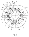
- FIG. 1 For example, an absorber system 1 with an absorber mass carrier 3a is shown which, as in FIG Fig. 3 illustrated, having two axially spaced absorber mass carrier elements 5a and 5b.
- Fig. 1 and 2 is the operating principle of the absorber system 1 by means of absorber mass units 8a, each with at least one absorber mass 7a, these absorber mass units 8a themselves, like Fig. 3 further shows axially located between the two absorber mass carrier elements 5a and 5b.
- the same operating principle also applies to a second absorber mass carrier 3b having second absorber mass units 8b with at least one absorber mass 7b, which in FIG Fig.
- absorber masses 7a is in the Fig. 1 and 2 in each case the absorber mass carrier element 5a arranged in the viewing direction axially in front of the absorber masses 7a is removed, and only the absorber mass carrier element 5b arranged axially behind the absorber masses 7a in the viewing direction is shown. As already mentioned, the absorber mass carrier element 5b is connected by spacers 11a to the absorber mass carrier element 5a.
- absorber masses 7a have each trained in pairs guideways 22 for receiving rolling bodies 20, wherein the guide tracks 22 are designed such that they allow a radial relative movement of the absorber masses 7a relative to the rolling bodies 20.
- the absorber masses 7a have, radially inward on their peripheral sides 42 adjacent stop sides 43.
- guideways 13 are provided, which have a curved course. As shown in Fig. 1 or 2 the guideways 13 each have an exit area 14, in which the respective guide track 13 has the greatest radial distance from a central axis 15, and via connection regions 17 which, extending circumferentially opposite one another, adjoin both sides of the output region 14.
- the guideways 22 provided on the absorber masses 7a, 7b also have a curved course, each having an exit region 24, in which the respective guideway 22 has the smallest radial distance from the central axis 15, and with connection regions 25 which extend circumferentially opposite each other , connect to both sides of the output area 24.
- the guideways 22 are each provided on both sides of a Tilgermassen scholars 35 of the respective absorber mass.
- This absorber mass center 35 is located in a middle extent radius 36a of the absorber masses 7a, which is arranged in driving operation at a distance R1 relative to the central axis 15.
- the state of the absorber masses 7a when driving is in Fig. 1 shown, and is when the absorber system 1 is operated at a speed at which the centrifugal force exceeds the weight.
- the absorber masses 7a strive radially outwards, so that the rolling bodies 20 each position themselves in the output region 24 of the respective guide track 22, that is to say in that region which has the smallest radial distance from the central axis 15.
- the rolling bodies 20 are supported in each case in the exit region 14 of the absorber mass carrier elements 5a and 5b, ie in that region which has the greatest radial distance from the central axis 15.
- the absorber masses 7a each have at their radially inner ends in each case a geometric Anformung 28 which has a first contact portion 26 in the peripheral middle part, in the peripheral side outer parts on the other hand via second contact areas 27.
- the first contact area 26 has an area center 37, which divides the first contact region 29 into molding halves 23.
- This geometric Anformung 28 acts in the manner to be described below with radially inward the absorber masses 7 a provided stops 31 which are taken together on an annular member 32.
- the annular member 32 has in the circumferential direction between two absorber masses 7a via a respective holder 34 which encloses a respective spacer 11 a, so that the holder 34 each serves as a Anschlagaufivity 38.
- the annular member 32 is thus rotatably on the absorber mass carrier element 5b and thus received on Tilgermassenlasi 3.
- a circumferentially extending annular body 33 acts between each two Anschlagaufivity 38 each with a stop profile 40.
- Anschlagaufillon 38 and stop profiles 40 together form stops 31 on the annular member 32nd
- the absorber masses 7a strive radially outwards under the effect of the centrifugal force so that the rolling elements 20 can respectively position themselves in the exit region 24 of the respective guideway 22 of the absorber masses 7a , Although torsional vibrations can enforce deflections of the absorber masses 7a in the circumferential direction, whereby the rolling elements 20 are deflected out of the output regions 14, 24 of the guideways 13, 22 in their connection regions 17, 25, however, with a decaying torsional vibration always a provision of the rolling elements 20 in the starting position below the effect of centrifugal force.
- the two absorber masses 7a located radially below the central axis 15 likewise fall radially inwards until their stop sides 43 with the first contact areas 26 formed thereon, which are relevant for the movement direction, abut on the associated stop profile 40 of the stop 31 on the annular body 33 of the annular component 32 have come, and until also the relevant for the direction of movement second contact portions 27 of the respective absorber masses 7a at the corresponding brackets 34 and thus at the Anschlagaufillon 38 of the annular member 32 come into abutment. In this way it is prevented that the two radially located below the central axis 15 absorber masses 7a reach with their peripheral sides 42 in abutment against each other.
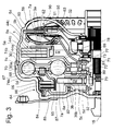
- Fig. 3 shows in detail, is for the absorber masses 7a provided on the first absorber mass carrier 3a, this axially between two absorber mass carrier elements 5a and 5b record, and for the absorber masses 7b on the second absorber mass carrier 3b, this axially between two absorber mass carrier elements 5c and 5d record. Furthermore, it is off Fig. 3 can be seen that the absorber masses 7a of the first absorber mass carrier 3a when driving have a mean radius of extent 36a, the absorber masses 7b of the second absorber mass carrier 3a, however, when driving over a mean extension radius 36b.
- the distance R1 of the mean extension radius 36a of the absorber masses 7a with respect to the central axis 15 is significantly greater than the distance R2 of the mean extension radius 36b of the absorber masses 7b with respect to the central axis 15.
- the absorber masses 7a thus provide - mass uniformity with the absorber masses 7b assuming a significantly higher Mass moment of inertia as the absorber masses 7a.
- the absorber mass carrier 3b is designed to be very compact radially, so that together with the absorber mass unit 8b it is able to make advantageous use of the free space in the axial extension region of a coupling device 64 of a coupling arrangement 56, but arranged radially inside it.
- the annular member 32 is provided whose function in connection with the Fig. 2 and 3 has already been dealt with in detail.
- the absorber mass units 8a, 8b provided on the two absorber mass carriers 3a, 3b are preferably suitable for repelling propulsion of an engine such as an internal combustion engine with different orders, however, the lower mass inertia second absorber mass unit 8b may also serve to to assist the first absorber mass unit 8a in the cancellation of excitations of a certain order, so that the second absorber mass unit 8b is at least substantially tuned to excitations of the same order as the first absorber mass unit 8a.
- the guide tracks 13 are at least substantially identical in the absorber masses 7a and 7b of the absorber mass units 8a and 8b. If, on the other hand, suggestions of different orders are to be redeemed, then the guideways differ from one another, provided that the same rolling elements 20 are to be used for both guideways for cost reasons.
- the first absorber mass unit 8a may be provided for the cancellation of orders of the second order, while the second absorber mass unit 8b may be for the cancellation of first order suggestions. This is advantageous when the engine preceding the absorber system 1 is designed as a 4-cylinder engine in which a cylinder deactivation leads to an operation with only two cylinders.
- the coupling arrangement 56 serving to receive the two absorber mass carriers 3a and 3b with their absorber mass units 8a and 8b has a housing 54 and has, as a hydrodynamic torque converter 90, a hydrodynamic circuit 60 with impeller 61, turbine wheel 62 and stator 63.
- the already mentioned coupling device 64 is connected to a clutch piston 65 and a friction disk clutch 66 is formed, wherein radially outer friction disk elements 84 of the friction disk clutch 66 are in meshing engagement with an outer wall 86 of the housing 54 and radially inner Reibusionn institute 85 of Reibusionnkupplung 66 in meshing engagement with a friction plate element support 87 which engages a damping input 67 of a damping device 70.
- the clutch device 64 can be moved between an engagement position and a disengagement position.
- the damping input 67 is connected via a first damping unit 68 to a damping intermediate part 74 which has two components 74a and 74b arranged at an axial distance from one another and held at a fixed axial distance by means of spacer elements 81.
- Via a second damping unit 69 the damping intermediate part 74 is connected to a damping output 72 which cooperates with a hub 71 acting as an output 73.
- the damping device 70 together with the absorber system 1 serves as a torsional vibration damper 30.
- the absorber mass carrier element 5a of the first absorber mass carrier 3a has a radial extension 78 engaging radially inward in order to make a connection 77 with the intermediate damping part 74 by means of the spacing elements 81.
- the second absorber mass carrier 3b is also connected to the damping intermediate part 74 by means of an axial compression 79 provided on the absorber mass carrier element 5d and extending in the direction of the damping device 70.
- the latter connection 80 is produced by means of welding.
- the two absorber mass carriers 3a and 3b of the absorber system 1 thus act on the respectively same components of the damping device 70, namely on the damping intermediate part 74, but it is avoided to arrange a absorber mass carrier in the direction of the torque transmission path in front of the drive-side damping unit 68.
- the reason for this is due to the fact that considerable torsional vibrations may be present in front of the drive-side damping unit 68 due to the lack of damping.
- the absorber mass carriers 3a and 3b are assigned to the damping intermediate part, 74, the drive-side damping unit 68 vibration-reducing.
- the respective associated absorber masses 7a, 7b may be designed to be low in mass for both absorber mass carriers 3a, 3b, and yet are deflected only to a slight extent when torsional vibrations occur in the circumferential direction.
- the absorber masses 7a, 7b the following must be added:
- the absorber masses 7a have a plurality of absorber mass elements 44a to 44c in the axial direction, while the absorber masses 7b are integrally formed in the axial direction.
- the absorber mass elements 44a to 44c are sheet metal elements in which the guideways 13a can be hardened at low cost over the entire web depth. Subsequently, the absorber mass elements 44a to 44c either, after riveting together, placed on the rolling elements 20, or the absorber mass elements 44a to 44c are placed without riveting on the rolling body 20.
- the absorber masses 7b which are integral in the axial direction are preferably made of solid steel, and are milled, for example, to obtain the shape intended for this purpose.
- the tolerances on the guideways of the corresponding absorber mass carrier elements can be limited and thereby the efficiency of the respective absorber mass unit 8b can be increased.
- the absorber masses 7a of the first absorber mass unit 8a may be integrally formed in the axial direction and the absorber masses 7b of the second absorber mass unit 8b may be formed axially with a plurality of absorber mass elements 44a to 44c.
- Other combinations are also possible, such as the formation of both damper masses 7a, 7b in the same way, so either both each with a plurality of Tilgermassenmaschinen, or both in one piece in the axial direction.
- damping units 68 and 69 are designed for full load so as to avoid running to an end stop within the torque range provided by a drive, such as an internal combustion engine, or when one of the damper units 68, 69 is at partial load to be, for that ensuring that only the output-side damping unit 69 experiences such a design, in which it is permitted that this damping unit 69 reaches an end stop within the torque range supplied by the drive.
- damping unit 69 it may be useful to design the output-side damping unit 69 to partial load, for example, if a damping unit of low rigidity is needed to suppress certain torsional vibrations. If this is not the case, both damping units 68, 69 are designed for full load, so that both damping units 68 and 69 are available within the torque range achievable by the respective drive.
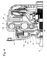
- the second absorber mass carrier 3b of the absorber system 1 is connected to the damping intermediate portion 74 of the damper 70 of the torsional vibration damper 30, but the absorber mass carrier 3b has only a single absorber mass carrier element 5c which is used to make the connection 80 with the intermediate damping member 74 with a direction towards the damper 70 expansive Axialausd Wegung 79 is provided.
- absorber masses 7b are arranged, which serve to form the second absorber mass unit 8b. Due to the saving of a absorber mass carrier element in relation to the in Fig. 3 shown construction space is created, which can be filled by additional absorber masses 7b of the second absorber mass unit 8b.
- the performance of the second absorber mass unit 8b compared to the in Fig. 3 shown embodiment without installation space disadvantages can be increased.
- connection 80 of the second absorber mass carrier 3b of the absorber system 1 is made radially larger than the central axis 15 by engaging the absorber mass carrier element 5d of the absorber mass carrier 3b on the spacers 81 of the intermediate damping element 74 of the damping device 70 of the torsional vibration damper 30.
- the two components 74a, 74b of the damping intermediate part 74 are held by the spacing elements 81 at a predetermined distance from one another.
- the absorber masses 7b of the second absorber mass unit 8b can also be radially enlarged, so that a comparison with the embodiment Fig. 3 significantly higher mass moment of inertia can be generated by the second absorber mass unit 8b.
- the mean extension radius 36b of the absorption mass unit 8b deviates from the comparable extension radius of the Figure 3 from, and thus the distance R2 'of this extension radius 36b relative to the central axis 15th
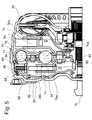
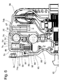
- Fig. 5 also has Fig. 6 the outer wall 86 of the housing 54 of the coupling arrangement 56 in the axial extension region region of the friction disc clutch 66 of the coupling device 64 undergo a radial widening in order to create additional installation space. Notwithstanding the execution according to Fig. 5 is included Fig. 6 Radially sealed within the outer wall 86 of the housing 54, the second absorber mass carrier 3b provided with the absorber mass unit 8b, so that this absorber mass carrier 3b, the coupling means 64 radially encloses.
- the radially further inwardly disposed coupling device 64 requires a radially outer friction plate element carrier 88, which is fastened to a cover 89 of the coupling arrangement 56 in the absence of a toothed engagement with the outer wall 86 of the housing 54.
- the radially outer friction plate element carrier 88 carries radially outwardly the annular member 32, which in terms of its functional determination in the Fig. 1 and 2 already shown and described for this purpose.
- the radially outer friction plate element carrier 88 is in operative connection via the friction disk elements 84, 85 with the radially inner friction disk element carrier 87, and therefore also with the damping input 67 of the damping device 70.
- the second absorber mass carrier 3a is formed with two absorber mass carrier elements 5c and 5d, wherein the absorber mass carrier element 5d is integrally formed with the component 74a of the intermediate damping part 74 of the damping device 70.
- the second absorber mass carrier 3b By arranging the second absorber mass carrier 3b closely within the outer wall 86 of the housing 54, the second absorber mass unit 8b is moved radially outward as far as possible with a radially large distance R2 'from the central axis 15.
- the absorber masses 7b of the second absorber mass unit 8b can also be used be enlarged radially, so that a respect to the embodiment according to Fig. 3 a much higher mass moment of inertia can be generated by the second absorber mass unit 8b.
- the mean extension radius 36b of the absorption mass unit 8b deviates from the comparable extension radius of the Figure 3 from, and thus also the distance R2 "of this extension radius 36b with respect to the central axis 15.
Landscapes
- Engineering & Computer Science (AREA)
- General Engineering & Computer Science (AREA)
- Physics & Mathematics (AREA)
- Acoustics & Sound (AREA)
- Aviation & Aerospace Engineering (AREA)
- Mechanical Engineering (AREA)
- Mechanical Operated Clutches (AREA)
Applications Claiming Priority (1)
| Application Number | Priority Date | Filing Date | Title |
|---|---|---|---|
| DE201310219503 DE102013219503A1 (de) | 2013-09-27 | 2013-09-27 | Torsionsschwingungsdämpfer |
Publications (2)
| Publication Number | Publication Date |
|---|---|
| EP2853772A1 true EP2853772A1 (fr) | 2015-04-01 |
| EP2853772B1 EP2853772B1 (fr) | 2018-09-26 |
Family
ID=51359313
Family Applications (1)
| Application Number | Title | Priority Date | Filing Date |
|---|---|---|---|
| EP14181711.4A Revoked EP2853772B1 (fr) | 2013-09-27 | 2014-08-21 | Amortisseur d'oscillations de torsion |
Country Status (2)
| Country | Link |
|---|---|
| EP (1) | EP2853772B1 (fr) |
| DE (1) | DE102013219503A1 (fr) |
Cited By (6)
| Publication number | Priority date | Publication date | Assignee | Title |
|---|---|---|---|---|
| US20150101450A1 (en) * | 2011-11-28 | 2015-04-16 | Schaeffler Technologies Gmbh & Co. Kg | Centrifugal force pendulum |
| WO2015149783A1 (fr) * | 2014-04-02 | 2015-10-08 | Schaeffler Technologies AG & Co. KG | Pendule centrifuge |
| WO2016012022A1 (fr) * | 2014-07-24 | 2016-01-28 | Schaeffler Technologies AG & Co. KG | Dispositif de transmission de couple et boîte de vitesses |
| WO2017067553A1 (fr) * | 2015-10-21 | 2017-04-27 | Schaeffler Technologies AG & Co. KG | Ensemble amortisseur de vibrations de torsion |
| CN113423971A (zh) * | 2019-02-13 | 2021-09-21 | 采埃孚股份公司 | 扭振减振组件 |
| DE102016204634B4 (de) | 2016-03-21 | 2023-07-27 | Schaeffler Technologies AG & Co. KG | Drehschwingungsisolationseinrichtung |
Citations (3)
| Publication number | Priority date | Publication date | Assignee | Title |
|---|---|---|---|---|
| DE102011010342A1 (de) | 2010-02-16 | 2011-08-18 | Schaeffler Technologies GmbH & Co. KG, 91074 | Drehmomentübertragungseinrichtung |
| WO2012168604A1 (fr) | 2011-06-07 | 2012-12-13 | Valeo Embrayages | Dispositif d'amortissement de torsion, notamment pour une transmission de vehicule automobile |
| EP2600030A2 (fr) * | 2011-12-01 | 2013-06-05 | Schaeffler Technologies AG & Co. KG | Convertisseur de couple |
Family Cites Families (18)
| Publication number | Priority date | Publication date | Assignee | Title |
|---|---|---|---|---|
| DD40068A1 (de) | 1960-04-13 | 1965-07-15 | Horst Kropp | Vorrichtung zum Ausgleich des freien Massenmomentes und zur Verbesserung des Ungleichförmigkeitsgrades von Kolbenmaschinen |
| DE10236752A1 (de) | 2002-08-10 | 2004-02-19 | Daimlerchrysler Ag | Antriebsstrang eines Kraftfahrzeuges |
| DE102005058783A1 (de) | 2005-12-09 | 2007-06-14 | Zf Friedrichshafen Ag | Torsionsschwingungsdämpfer |
| DE112008003167B4 (de) | 2007-11-29 | 2016-07-21 | Schaeffler Technologies AG & Co. KG | Kraftübertragungsvorrichtung mit einem drehzahladaptiven Tilger und Verfahren zur Verbesserung des Dämpfungsverhaltens |
| DE102009052055A1 (de) | 2008-11-27 | 2010-10-21 | Luk Lamellen Und Kupplungsbau Beteiligungs Kg | Fliehkraftpendeleinrichtung mit Pendelmassen unterschiedlicher Ordnung |
| DE102009002481B4 (de) | 2008-12-10 | 2022-06-02 | Zf Friedrichshafen Ag | Antriebssystem mit Drehmomentübertragungsanordnung und hydrodynamische Kopplungsanordnung |
| DE102010053548A1 (de) * | 2009-12-14 | 2011-06-16 | Schaeffler Technologies Gmbh & Co. Kg | Dämpfungseinrichtung zur Dämpfung von Drehschwingungen |
| DE102010029464A1 (de) | 2010-05-28 | 2011-12-01 | Zf Friedrichshafen Ag | Torsionsschwingungsdämpferanordnung und Schwingungsdämpfereinrichtung, insbesondere in einer Torsionsschwingungsdämpferanordnung |
| DE102011104415B4 (de) | 2010-06-29 | 2019-05-02 | Schaeffler Technologies AG & Co. KG | Schwingungsdämpfungseinrichtung |
| DE102011085983B4 (de) | 2010-11-29 | 2020-03-05 | Schaeffler Technologies AG & Co. KG | Fliehkraftpendeleinrichtung |
| DE112012001776A5 (de) | 2011-04-21 | 2014-01-23 | Schaeffler Technologies AG & Co. KG | Drehmomentwandler |
| DE102011017658B4 (de) | 2011-04-28 | 2021-03-18 | Zf Friedrichshafen Ag | Hydrodynamische Kopplungsanordnung, insbesondere hydrodynamischer Drehmomentwandler |
| DE102011076790B4 (de) | 2011-05-31 | 2023-07-13 | Zf Friedrichshafen Ag | Antriebssystem für ein Fahrzeug |
| DE102012205792A1 (de) | 2011-06-07 | 2012-12-13 | Zf Friedrichshafen Ag | Antriebssystem für ein Fahrzeug |
| DE102011084744A1 (de) | 2011-10-19 | 2013-04-25 | Zf Friedrichshafen Ag | Antriebssystem für ein Fahrzeug |
| DE102012220278A1 (de) | 2011-11-30 | 2013-06-06 | Schaeffler Technologies AG & Co. KG | Drehmomentwandler |
| EP2788604B1 (fr) | 2011-12-05 | 2017-03-01 | Schaeffler Technologies AG & Co. KG | Chaîne cinématique |
| DE102013204713A1 (de) * | 2013-03-18 | 2014-09-18 | Zf Friedrichshafen Ag | Tilgerschwingungsdämpfer |
-
2013
- 2013-09-27 DE DE201310219503 patent/DE102013219503A1/de not_active Ceased
-
2014
- 2014-08-21 EP EP14181711.4A patent/EP2853772B1/fr not_active Revoked
Patent Citations (3)
| Publication number | Priority date | Publication date | Assignee | Title |
|---|---|---|---|---|
| DE102011010342A1 (de) | 2010-02-16 | 2011-08-18 | Schaeffler Technologies GmbH & Co. KG, 91074 | Drehmomentübertragungseinrichtung |
| WO2012168604A1 (fr) | 2011-06-07 | 2012-12-13 | Valeo Embrayages | Dispositif d'amortissement de torsion, notamment pour une transmission de vehicule automobile |
| EP2600030A2 (fr) * | 2011-12-01 | 2013-06-05 | Schaeffler Technologies AG & Co. KG | Convertisseur de couple |
Cited By (8)
| Publication number | Priority date | Publication date | Assignee | Title |
|---|---|---|---|---|
| US20150101450A1 (en) * | 2011-11-28 | 2015-04-16 | Schaeffler Technologies Gmbh & Co. Kg | Centrifugal force pendulum |
| US9631696B2 (en) * | 2011-11-28 | 2017-04-25 | Schaeffler Technologies AG & Co. KG | Centrifugal force pendulum |
| WO2015149783A1 (fr) * | 2014-04-02 | 2015-10-08 | Schaeffler Technologies AG & Co. KG | Pendule centrifuge |
| WO2016012022A1 (fr) * | 2014-07-24 | 2016-01-28 | Schaeffler Technologies AG & Co. KG | Dispositif de transmission de couple et boîte de vitesses |
| WO2017067553A1 (fr) * | 2015-10-21 | 2017-04-27 | Schaeffler Technologies AG & Co. KG | Ensemble amortisseur de vibrations de torsion |
| DE102016204634B4 (de) | 2016-03-21 | 2023-07-27 | Schaeffler Technologies AG & Co. KG | Drehschwingungsisolationseinrichtung |
| CN113423971A (zh) * | 2019-02-13 | 2021-09-21 | 采埃孚股份公司 | 扭振减振组件 |
| CN113423971B (zh) * | 2019-02-13 | 2023-10-20 | 采埃孚股份公司 | 扭振减振组件 |
Also Published As
| Publication number | Publication date |
|---|---|
| EP2853772B1 (fr) | 2018-09-26 |
| DE102013219503A1 (de) | 2015-04-23 |
Similar Documents
| Publication | Publication Date | Title |
|---|---|---|
| EP2853773B1 (fr) | Amortisseur d'oscillations de torsion | |
| EP2909503B1 (fr) | Dispositif amortisseur de vibrations de torsion ayant une caractéristique fonction de la vitesse de rotation | |
| EP2853772B1 (fr) | Amortisseur d'oscillations de torsion | |
| WO2009146673A1 (fr) | Amortisseur de vibrations de torsion avec pendule à force centrifuge | |
| WO2014005903A1 (fr) | Amortisseur de vibrations de torsion et procédé permettant d'amortir les vibrations de la chaîne cinématique d'un véhicule automobile | |
| EP2212587B1 (fr) | Dispositif d'accouplement hydrodynamique | |
| EP2836737A1 (fr) | Ensemble d'amortissement des vibrations torsionnelles | |
| DE102018113585B4 (de) | Drehschwingungsdämpfer | |
| DE102014207258A1 (de) | Torsionsschwingungsdämpfer mit einer Dämpfungseinrichtung, einem Tilgersystem und einer Masseeinrichtung | |
| EP2909502A1 (fr) | Système d'amortissement des vibrations de torsion à précontrainte | |
| DE10205767B4 (de) | Lamellen-Kupplungseinrichtung mit einer eingangseitigen Dämpfungs- oder/und Federelementanordnung | |
| EP2853771B1 (fr) | Amortisseur d'oscillations de torsion | |
| EP2853770B1 (fr) | Système d'absorption | |
| DE102014220901A1 (de) | Baueinheit einer Kopplungsanordnung mit einer Schwingungsreduzierungseinrichtung und mit einer Kupplungseinrichtung | |
| DE102014217488B4 (de) | Drehschwingungsdämpfer | |
| DE102014207260A1 (de) | Torsionsschwingungsdämpfer mit einer Dämpfungseinrichtung, einem Tilgersystem und einer Masseeinrichtung | |
| WO2014023306A1 (fr) | Dispositif de pendule à force centrifuge | |
| DE102011017657A1 (de) | Drehmomentübertragungsanordnung für den Antriebsstrang eines Fahrzeugs | |
| DE102014213618A1 (de) | Nassraum-Rotationsbauteil, Nassraum-Baugruppe sowie Drehmomentübertragungseinrichtung | |
| DE102012219194A1 (de) | Torsionsschwingungsdämpferanordnung | |
| DE102015220234A1 (de) | Dämpfungsanordnung für wenigstens eine Tilgermasse | |
| DE102020112024A1 (de) | Drehschwingungsdämpfer | |
| EP3207276A1 (fr) | Dispositif de réduction de vibrations | |
| DE102015202355A1 (de) | Fliehkraftpendeleinrichtung, Dämpfereinrichtung sowie Drehmomentübertragungseinrichtung | |
| DE102014218112A1 (de) | Dämpferflansch, Torsionsschwingungsdämpfer, Modulaufbau für einen Torsionsschwingungsdämpfer sowie Drehmomentübertragungseinrichtung |
Legal Events
| Date | Code | Title | Description |
|---|---|---|---|
| PUAI | Public reference made under article 153(3) epc to a published international application that has entered the european phase |
Free format text: ORIGINAL CODE: 0009012 |
|
| 17P | Request for examination filed |
Effective date: 20140821 |
|
| AK | Designated contracting states |
Kind code of ref document: A1 Designated state(s): AL AT BE BG CH CY CZ DE DK EE ES FI FR GB GR HR HU IE IS IT LI LT LU LV MC MK MT NL NO PL PT RO RS SE SI SK SM TR |
|
| AX | Request for extension of the european patent |
Extension state: BA ME |
|
| R17P | Request for examination filed (corrected) |
Effective date: 20150702 |
|
| STAA | Information on the status of an ep patent application or granted ep patent |
Free format text: STATUS: EXAMINATION IS IN PROGRESS |
|
| 17Q | First examination report despatched |
Effective date: 20161213 |
|
| GRAP | Despatch of communication of intention to grant a patent |
Free format text: ORIGINAL CODE: EPIDOSNIGR1 |
|
| STAA | Information on the status of an ep patent application or granted ep patent |
Free format text: STATUS: GRANT OF PATENT IS INTENDED |
|
| INTG | Intention to grant announced |
Effective date: 20180517 |
|
| GRAS | Grant fee paid |
Free format text: ORIGINAL CODE: EPIDOSNIGR3 |
|
| GRAA | (expected) grant |
Free format text: ORIGINAL CODE: 0009210 |
|
| STAA | Information on the status of an ep patent application or granted ep patent |
Free format text: STATUS: THE PATENT HAS BEEN GRANTED |
|
| AK | Designated contracting states |
Kind code of ref document: B1 Designated state(s): AL AT BE BG CH CY CZ DE DK EE ES FI FR GB GR HR HU IE IS IT LI LT LU LV MC MK MT NL NO PL PT RO RS SE SI SK SM TR |
|
| REG | Reference to a national code |
Ref country code: GB Ref legal event code: FG4D Free format text: NOT ENGLISH |
|
| REG | Reference to a national code |
Ref country code: CH Ref legal event code: EP |
|
| REG | Reference to a national code |
Ref country code: AT Ref legal event code: REF Ref document number: 1046394 Country of ref document: AT Kind code of ref document: T Effective date: 20181015 |
|
| REG | Reference to a national code |
Ref country code: IE Ref legal event code: FG4D Free format text: LANGUAGE OF EP DOCUMENT: GERMAN |
|
| REG | Reference to a national code |
Ref country code: DE Ref legal event code: R096 Ref document number: 502014009559 Country of ref document: DE |
|
| REG | Reference to a national code |
Ref country code: NL Ref legal event code: MP Effective date: 20180926 |
|
| PG25 | Lapsed in a contracting state [announced via postgrant information from national office to epo] |
Ref country code: LT Free format text: LAPSE BECAUSE OF FAILURE TO SUBMIT A TRANSLATION OF THE DESCRIPTION OR TO PAY THE FEE WITHIN THE PRESCRIBED TIME-LIMIT Effective date: 20180926 Ref country code: GR Free format text: LAPSE BECAUSE OF FAILURE TO SUBMIT A TRANSLATION OF THE DESCRIPTION OR TO PAY THE FEE WITHIN THE PRESCRIBED TIME-LIMIT Effective date: 20181227 Ref country code: NO Free format text: LAPSE BECAUSE OF FAILURE TO SUBMIT A TRANSLATION OF THE DESCRIPTION OR TO PAY THE FEE WITHIN THE PRESCRIBED TIME-LIMIT Effective date: 20181226 Ref country code: BG Free format text: LAPSE BECAUSE OF FAILURE TO SUBMIT A TRANSLATION OF THE DESCRIPTION OR TO PAY THE FEE WITHIN THE PRESCRIBED TIME-LIMIT Effective date: 20181226 Ref country code: SE Free format text: LAPSE BECAUSE OF FAILURE TO SUBMIT A TRANSLATION OF THE DESCRIPTION OR TO PAY THE FEE WITHIN THE PRESCRIBED TIME-LIMIT Effective date: 20180926 Ref country code: RS Free format text: LAPSE BECAUSE OF FAILURE TO SUBMIT A TRANSLATION OF THE DESCRIPTION OR TO PAY THE FEE WITHIN THE PRESCRIBED TIME-LIMIT Effective date: 20180926 Ref country code: FI Free format text: LAPSE BECAUSE OF FAILURE TO SUBMIT A TRANSLATION OF THE DESCRIPTION OR TO PAY THE FEE WITHIN THE PRESCRIBED TIME-LIMIT Effective date: 20180926 |
|
| REG | Reference to a national code |
Ref country code: LT Ref legal event code: MG4D |
|
| PG25 | Lapsed in a contracting state [announced via postgrant information from national office to epo] |
Ref country code: AL Free format text: LAPSE BECAUSE OF FAILURE TO SUBMIT A TRANSLATION OF THE DESCRIPTION OR TO PAY THE FEE WITHIN THE PRESCRIBED TIME-LIMIT Effective date: 20180926 Ref country code: HR Free format text: LAPSE BECAUSE OF FAILURE TO SUBMIT A TRANSLATION OF THE DESCRIPTION OR TO PAY THE FEE WITHIN THE PRESCRIBED TIME-LIMIT Effective date: 20180926 Ref country code: LV Free format text: LAPSE BECAUSE OF FAILURE TO SUBMIT A TRANSLATION OF THE DESCRIPTION OR TO PAY THE FEE WITHIN THE PRESCRIBED TIME-LIMIT Effective date: 20180926 |
|
| PG25 | Lapsed in a contracting state [announced via postgrant information from national office to epo] |
Ref country code: IT Free format text: LAPSE BECAUSE OF FAILURE TO SUBMIT A TRANSLATION OF THE DESCRIPTION OR TO PAY THE FEE WITHIN THE PRESCRIBED TIME-LIMIT Effective date: 20180926 Ref country code: EE Free format text: LAPSE BECAUSE OF FAILURE TO SUBMIT A TRANSLATION OF THE DESCRIPTION OR TO PAY THE FEE WITHIN THE PRESCRIBED TIME-LIMIT Effective date: 20180926 Ref country code: NL Free format text: LAPSE BECAUSE OF FAILURE TO SUBMIT A TRANSLATION OF THE DESCRIPTION OR TO PAY THE FEE WITHIN THE PRESCRIBED TIME-LIMIT Effective date: 20180926 Ref country code: RO Free format text: LAPSE BECAUSE OF FAILURE TO SUBMIT A TRANSLATION OF THE DESCRIPTION OR TO PAY THE FEE WITHIN THE PRESCRIBED TIME-LIMIT Effective date: 20180926 Ref country code: IS Free format text: LAPSE BECAUSE OF FAILURE TO SUBMIT A TRANSLATION OF THE DESCRIPTION OR TO PAY THE FEE WITHIN THE PRESCRIBED TIME-LIMIT Effective date: 20190126 Ref country code: CZ Free format text: LAPSE BECAUSE OF FAILURE TO SUBMIT A TRANSLATION OF THE DESCRIPTION OR TO PAY THE FEE WITHIN THE PRESCRIBED TIME-LIMIT Effective date: 20180926 Ref country code: PL Free format text: LAPSE BECAUSE OF FAILURE TO SUBMIT A TRANSLATION OF THE DESCRIPTION OR TO PAY THE FEE WITHIN THE PRESCRIBED TIME-LIMIT Effective date: 20180926 Ref country code: ES Free format text: LAPSE BECAUSE OF FAILURE TO SUBMIT A TRANSLATION OF THE DESCRIPTION OR TO PAY THE FEE WITHIN THE PRESCRIBED TIME-LIMIT Effective date: 20180926 |
|
| PG25 | Lapsed in a contracting state [announced via postgrant information from national office to epo] |
Ref country code: PT Free format text: LAPSE BECAUSE OF FAILURE TO SUBMIT A TRANSLATION OF THE DESCRIPTION OR TO PAY THE FEE WITHIN THE PRESCRIBED TIME-LIMIT Effective date: 20190126 Ref country code: SK Free format text: LAPSE BECAUSE OF FAILURE TO SUBMIT A TRANSLATION OF THE DESCRIPTION OR TO PAY THE FEE WITHIN THE PRESCRIBED TIME-LIMIT Effective date: 20180926 Ref country code: SM Free format text: LAPSE BECAUSE OF FAILURE TO SUBMIT A TRANSLATION OF THE DESCRIPTION OR TO PAY THE FEE WITHIN THE PRESCRIBED TIME-LIMIT Effective date: 20180926 |
|
| REG | Reference to a national code |
Ref country code: DE Ref legal event code: R026 Ref document number: 502014009559 Country of ref document: DE |
|
| PLBI | Opposition filed |
Free format text: ORIGINAL CODE: 0009260 |
|
| PLAX | Notice of opposition and request to file observation + time limit sent |
Free format text: ORIGINAL CODE: EPIDOSNOBS2 |
|
| 26 | Opposition filed |
Opponent name: VALEO EMBRAYAGES Effective date: 20190626 Opponent name: SCHAEFFLER TECHNOLOGIES AG & CO. KG Effective date: 20190626 |
|
| PG25 | Lapsed in a contracting state [announced via postgrant information from national office to epo] |
Ref country code: DK Free format text: LAPSE BECAUSE OF FAILURE TO SUBMIT A TRANSLATION OF THE DESCRIPTION OR TO PAY THE FEE WITHIN THE PRESCRIBED TIME-LIMIT Effective date: 20180926 |
|
| PLBB | Reply of patent proprietor to notice(s) of opposition received |
Free format text: ORIGINAL CODE: EPIDOSNOBS3 |
|
| PG25 | Lapsed in a contracting state [announced via postgrant information from national office to epo] |
Ref country code: SI Free format text: LAPSE BECAUSE OF FAILURE TO SUBMIT A TRANSLATION OF THE DESCRIPTION OR TO PAY THE FEE WITHIN THE PRESCRIBED TIME-LIMIT Effective date: 20180926 |
|
| PG25 | Lapsed in a contracting state [announced via postgrant information from national office to epo] |
Ref country code: TR Free format text: LAPSE BECAUSE OF FAILURE TO SUBMIT A TRANSLATION OF THE DESCRIPTION OR TO PAY THE FEE WITHIN THE PRESCRIBED TIME-LIMIT Effective date: 20180926 |
|
| GBPC | Gb: european patent ceased through non-payment of renewal fee |
Effective date: 20190821 |
|
| PG25 | Lapsed in a contracting state [announced via postgrant information from national office to epo] |
Ref country code: LU Free format text: LAPSE BECAUSE OF NON-PAYMENT OF DUE FEES Effective date: 20190821 Ref country code: MC Free format text: LAPSE BECAUSE OF FAILURE TO SUBMIT A TRANSLATION OF THE DESCRIPTION OR TO PAY THE FEE WITHIN THE PRESCRIBED TIME-LIMIT Effective date: 20180926 Ref country code: LI Free format text: LAPSE BECAUSE OF NON-PAYMENT OF DUE FEES Effective date: 20190831 Ref country code: CH Free format text: LAPSE BECAUSE OF NON-PAYMENT OF DUE FEES Effective date: 20190831 |
|
| REG | Reference to a national code |
Ref country code: BE Ref legal event code: MM Effective date: 20190831 |
|
| PG25 | Lapsed in a contracting state [announced via postgrant information from national office to epo] |
Ref country code: IE Free format text: LAPSE BECAUSE OF NON-PAYMENT OF DUE FEES Effective date: 20190821 |
|
| PG25 | Lapsed in a contracting state [announced via postgrant information from national office to epo] |
Ref country code: BE Free format text: LAPSE BECAUSE OF NON-PAYMENT OF DUE FEES Effective date: 20190831 Ref country code: GB Free format text: LAPSE BECAUSE OF NON-PAYMENT OF DUE FEES Effective date: 20190821 |
|
| REG | Reference to a national code |
Ref country code: AT Ref legal event code: MM01 Ref document number: 1046394 Country of ref document: AT Kind code of ref document: T Effective date: 20190821 |
|
| PG25 | Lapsed in a contracting state [announced via postgrant information from national office to epo] |
Ref country code: AT Free format text: LAPSE BECAUSE OF NON-PAYMENT OF DUE FEES Effective date: 20190821 |
|
| PG25 | Lapsed in a contracting state [announced via postgrant information from national office to epo] |
Ref country code: CY Free format text: LAPSE BECAUSE OF FAILURE TO SUBMIT A TRANSLATION OF THE DESCRIPTION OR TO PAY THE FEE WITHIN THE PRESCRIBED TIME-LIMIT Effective date: 20180926 |
|
| PG25 | Lapsed in a contracting state [announced via postgrant information from national office to epo] |
Ref country code: HU Free format text: LAPSE BECAUSE OF FAILURE TO SUBMIT A TRANSLATION OF THE DESCRIPTION OR TO PAY THE FEE WITHIN THE PRESCRIBED TIME-LIMIT; INVALID AB INITIO Effective date: 20140821 Ref country code: MT Free format text: LAPSE BECAUSE OF FAILURE TO SUBMIT A TRANSLATION OF THE DESCRIPTION OR TO PAY THE FEE WITHIN THE PRESCRIBED TIME-LIMIT Effective date: 20180926 |
|
| PLAB | Opposition data, opponent's data or that of the opponent's representative modified |
Free format text: ORIGINAL CODE: 0009299OPPO |
|
| R26 | Opposition filed (corrected) |
Opponent name: VALEO EMBRAYAGES Effective date: 20190626 |
|
| RDAF | Communication despatched that patent is revoked |
Free format text: ORIGINAL CODE: EPIDOSNREV1 |
|
| APBM | Appeal reference recorded |
Free format text: ORIGINAL CODE: EPIDOSNREFNO |
|
| APBP | Date of receipt of notice of appeal recorded |
Free format text: ORIGINAL CODE: EPIDOSNNOA2O |
|
| APAH | Appeal reference modified |
Free format text: ORIGINAL CODE: EPIDOSCREFNO |
|
| PG25 | Lapsed in a contracting state [announced via postgrant information from national office to epo] |
Ref country code: MK Free format text: LAPSE BECAUSE OF FAILURE TO SUBMIT A TRANSLATION OF THE DESCRIPTION OR TO PAY THE FEE WITHIN THE PRESCRIBED TIME-LIMIT Effective date: 20180926 |
|
| APBQ | Date of receipt of statement of grounds of appeal recorded |
Free format text: ORIGINAL CODE: EPIDOSNNOA3O |
|
| P01 | Opt-out of the competence of the unified patent court (upc) registered |
Effective date: 20230528 |
|
| PGFP | Annual fee paid to national office [announced via postgrant information from national office to epo] |
Ref country code: FR Payment date: 20230703 Year of fee payment: 10 |
|
| PGFP | Annual fee paid to national office [announced via postgrant information from national office to epo] |
Ref country code: DE Payment date: 20240625 Year of fee payment: 11 |
|
| REG | Reference to a national code |
Ref country code: DE Ref legal event code: R103 Ref document number: 502014009559 Country of ref document: DE Ref country code: DE Ref legal event code: R064 Ref document number: 502014009559 Country of ref document: DE |
|
| APBU | Appeal procedure closed |
Free format text: ORIGINAL CODE: EPIDOSNNOA9O |
|
| RDAG | Patent revoked |
Free format text: ORIGINAL CODE: 0009271 |
|
| STAA | Information on the status of an ep patent application or granted ep patent |
Free format text: STATUS: PATENT REVOKED |
|
| REG | Reference to a national code |
Ref country code: CH Ref legal event code: PL |
|
| 27W | Patent revoked |
Effective date: 20250122 |
|
| REG | Reference to a national code |
Ref country code: AT Ref legal event code: MA03 Ref document number: 1046394 Country of ref document: AT Kind code of ref document: T Effective date: 20250122 |