EP2853884A1 - Verfahren zur Bestimmung von Metallen in Ölproben aus Schmieröl von Maschinen - Google Patents
Verfahren zur Bestimmung von Metallen in Ölproben aus Schmieröl von Maschinen Download PDFInfo
- Publication number
- EP2853884A1 EP2853884A1 EP13185938.1A EP13185938A EP2853884A1 EP 2853884 A1 EP2853884 A1 EP 2853884A1 EP 13185938 A EP13185938 A EP 13185938A EP 2853884 A1 EP2853884 A1 EP 2853884A1
- Authority
- EP
- European Patent Office
- Prior art keywords
- quantum dot
- additional
- metal
- oil
- oil sample
- Prior art date
- Legal status (The legal status is an assumption and is not a legal conclusion. Google has not performed a legal analysis and makes no representation as to the accuracy of the status listed.)
- Withdrawn
Links
- 229910052751 metal Inorganic materials 0.000 title claims abstract description 202
- 239000002184 metal Substances 0.000 title claims abstract description 202
- 239000003921 oil Substances 0.000 title description 139
- 238000000034 method Methods 0.000 title description 39
- 150000002739 metals Chemical class 0.000 title description 7
- 239000010687 lubricating oil Substances 0.000 title description 4
- 239000002096 quantum dot Substances 0.000 claims abstract description 161
- 238000002189 fluorescence spectrum Methods 0.000 claims abstract description 74
- 238000012360 testing method Methods 0.000 claims abstract description 62
- 238000010791 quenching Methods 0.000 claims abstract description 28
- 230000000171 quenching effect Effects 0.000 claims abstract description 28
- 230000005670 electromagnetic radiation Effects 0.000 claims abstract description 25
- 238000002866 fluorescence resonance energy transfer Methods 0.000 claims abstract description 12
- 239000000314 lubricant Substances 0.000 claims abstract description 7
- 230000005855 radiation Effects 0.000 claims description 24
- 239000000463 material Substances 0.000 claims description 19
- 239000004065 semiconductor Substances 0.000 claims description 9
- RWSXRVCMGQZWBV-WDSKDSINSA-N glutathione Chemical compound OC(=O)[C@@H](N)CCC(=O)N[C@@H](CS)C(=O)NCC(O)=O RWSXRVCMGQZWBV-WDSKDSINSA-N 0.000 description 10
- WUPHOULIZUERAE-UHFFFAOYSA-N 3-(oxolan-2-yl)propanoic acid Chemical compound OC(=O)CCC1CCCO1 WUPHOULIZUERAE-UHFFFAOYSA-N 0.000 description 7
- 229910052980 cadmium sulfide Inorganic materials 0.000 description 7
- MARUHZGHZWCEQU-UHFFFAOYSA-N 5-phenyl-2h-tetrazole Chemical compound C1=CC=CC=C1C1=NNN=N1 MARUHZGHZWCEQU-UHFFFAOYSA-N 0.000 description 5
- 239000007853 buffer solution Substances 0.000 description 5
- 229960003180 glutathione Drugs 0.000 description 5
- 239000002159 nanocrystal Substances 0.000 description 5
- 239000010949 copper Substances 0.000 description 4
- PXHVJJICTQNCMI-UHFFFAOYSA-N Nickel Chemical compound [Ni] PXHVJJICTQNCMI-UHFFFAOYSA-N 0.000 description 3
- PJUIMOJAAPLTRJ-UHFFFAOYSA-N monothioglycerol Chemical compound OCC(O)CS PJUIMOJAAPLTRJ-UHFFFAOYSA-N 0.000 description 3
- 239000013307 optical fiber Substances 0.000 description 3
- 229940035024 thioglycerol Drugs 0.000 description 3
- RYGMFSIKBFXOCR-UHFFFAOYSA-N Copper Chemical compound [Cu] RYGMFSIKBFXOCR-UHFFFAOYSA-N 0.000 description 2
- XEEYBQQBJWHFJM-UHFFFAOYSA-N Iron Chemical compound [Fe] XEEYBQQBJWHFJM-UHFFFAOYSA-N 0.000 description 2
- ATJFFYVFTNAWJD-UHFFFAOYSA-N Tin Chemical compound [Sn] ATJFFYVFTNAWJD-UHFFFAOYSA-N 0.000 description 2
- 238000004458 analytical method Methods 0.000 description 2
- 229910052802 copper Inorganic materials 0.000 description 2
- 238000004519 manufacturing process Methods 0.000 description 2
- 238000012986 modification Methods 0.000 description 2
- 230000004048 modification Effects 0.000 description 2
- 230000000737 periodic effect Effects 0.000 description 2
- 239000000126 substance Substances 0.000 description 2
- 239000010936 titanium Substances 0.000 description 2
- JPVYNHNXODAKFH-UHFFFAOYSA-N Cu2+ Chemical compound [Cu+2] JPVYNHNXODAKFH-UHFFFAOYSA-N 0.000 description 1
- 108010024636 Glutathione Proteins 0.000 description 1
- GPXJNWSHGFTCBW-UHFFFAOYSA-N Indium phosphide Chemical compound [In]#P GPXJNWSHGFTCBW-UHFFFAOYSA-N 0.000 description 1
- BQCADISMDOOEFD-UHFFFAOYSA-N Silver Chemical compound [Ag] BQCADISMDOOEFD-UHFFFAOYSA-N 0.000 description 1
- RTAQQCXQSZGOHL-UHFFFAOYSA-N Titanium Chemical compound [Ti] RTAQQCXQSZGOHL-UHFFFAOYSA-N 0.000 description 1
- 229910052782 aluminium Inorganic materials 0.000 description 1
- XAGFODPZIPBFFR-UHFFFAOYSA-N aluminium Chemical compound [Al] XAGFODPZIPBFFR-UHFFFAOYSA-N 0.000 description 1
- 230000005540 biological transmission Effects 0.000 description 1
- 229910052793 cadmium Inorganic materials 0.000 description 1
- BDOSMKKIYDKNTQ-UHFFFAOYSA-N cadmium atom Chemical compound [Cd] BDOSMKKIYDKNTQ-UHFFFAOYSA-N 0.000 description 1
- AQCDIIAORKRFCD-UHFFFAOYSA-N cadmium selenide Chemical compound [Cd]=[Se] AQCDIIAORKRFCD-UHFFFAOYSA-N 0.000 description 1
- JLATXDOZXBEBJX-UHFFFAOYSA-N cadmium(2+);selenium(2-);sulfide Chemical compound [S-2].[Se-2].[Cd+2].[Cd+2] JLATXDOZXBEBJX-UHFFFAOYSA-N 0.000 description 1
- 239000003086 colorant Substances 0.000 description 1
- 229910001431 copper ion Inorganic materials 0.000 description 1
- 230000008878 coupling Effects 0.000 description 1
- 238000010168 coupling process Methods 0.000 description 1
- 238000005859 coupling reaction Methods 0.000 description 1
- 238000001514 detection method Methods 0.000 description 1
- 239000012530 fluid Substances 0.000 description 1
- 230000007849 functional defect Effects 0.000 description 1
- 239000011521 glass Substances 0.000 description 1
- RPQDHPTXJYYUPQ-UHFFFAOYSA-N indium arsenide Chemical compound [In]#[As] RPQDHPTXJYYUPQ-UHFFFAOYSA-N 0.000 description 1
- RVPVRDXYQKGNMQ-UHFFFAOYSA-N lead(2+) Chemical compound [Pb+2] RVPVRDXYQKGNMQ-UHFFFAOYSA-N 0.000 description 1
- 238000005461 lubrication Methods 0.000 description 1
- 238000012423 maintenance Methods 0.000 description 1
- 229910052759 nickel Inorganic materials 0.000 description 1
- 230000003287 optical effect Effects 0.000 description 1
- 238000002165 resonance energy transfer Methods 0.000 description 1
- 229910052709 silver Inorganic materials 0.000 description 1
- 239000004332 silver Substances 0.000 description 1
- 238000001228 spectrum Methods 0.000 description 1
- 239000000758 substrate Substances 0.000 description 1
- 229910052719 titanium Inorganic materials 0.000 description 1
- LEONUFNNVUYDNQ-UHFFFAOYSA-N vanadium atom Chemical compound [V] LEONUFNNVUYDNQ-UHFFFAOYSA-N 0.000 description 1
Images

Classifications
-
- G—PHYSICS
- G01—MEASURING; TESTING
- G01N—INVESTIGATING OR ANALYSING MATERIALS BY DETERMINING THEIR CHEMICAL OR PHYSICAL PROPERTIES
- G01N21/00—Investigating or analysing materials by the use of optical means, i.e. using sub-millimetre waves, infrared, visible or ultraviolet light
- G01N21/62—Systems in which the material investigated is excited whereby it emits light or causes a change in wavelength of the incident light
- G01N21/63—Systems in which the material investigated is excited whereby it emits light or causes a change in wavelength of the incident light optically excited
- G01N21/64—Fluorescence; Phosphorescence
- G01N21/6428—Measuring fluorescence of fluorescent products of reactions or of fluorochrome labelled reactive substances, e.g. measuring quenching effects, using measuring "optrodes"
- G01N21/643—Measuring fluorescence of fluorescent products of reactions or of fluorochrome labelled reactive substances, e.g. measuring quenching effects, using measuring "optrodes" non-biological material
-
- G—PHYSICS
- G01—MEASURING; TESTING
- G01N—INVESTIGATING OR ANALYSING MATERIALS BY DETERMINING THEIR CHEMICAL OR PHYSICAL PROPERTIES
- G01N21/00—Investigating or analysing materials by the use of optical means, i.e. using sub-millimetre waves, infrared, visible or ultraviolet light
- G01N21/62—Systems in which the material investigated is excited whereby it emits light or causes a change in wavelength of the incident light
- G01N21/63—Systems in which the material investigated is excited whereby it emits light or causes a change in wavelength of the incident light optically excited
- G01N21/64—Fluorescence; Phosphorescence
- G01N21/6489—Photoluminescence of semiconductors
-
- G—PHYSICS
- G01—MEASURING; TESTING
- G01N—INVESTIGATING OR ANALYSING MATERIALS BY DETERMINING THEIR CHEMICAL OR PHYSICAL PROPERTIES
- G01N33/00—Investigating or analysing materials by specific methods not covered by groups G01N1/00 - G01N31/00
- G01N33/26—Oils; Viscous liquids; Paints; Inks
- G01N33/28—Oils, i.e. hydrocarbon liquids
- G01N33/2835—Specific substances contained in the oils or fuels
-
- G—PHYSICS
- G01—MEASURING; TESTING
- G01N—INVESTIGATING OR ANALYSING MATERIALS BY DETERMINING THEIR CHEMICAL OR PHYSICAL PROPERTIES
- G01N33/00—Investigating or analysing materials by specific methods not covered by groups G01N1/00 - G01N31/00
- G01N33/26—Oils; Viscous liquids; Paints; Inks
- G01N33/28—Oils, i.e. hydrocarbon liquids
- G01N33/2888—Lubricating oil characteristics, e.g. deterioration
-
- G—PHYSICS
- G01—MEASURING; TESTING
- G01N—INVESTIGATING OR ANALYSING MATERIALS BY DETERMINING THEIR CHEMICAL OR PHYSICAL PROPERTIES
- G01N21/00—Investigating or analysing materials by the use of optical means, i.e. using sub-millimetre waves, infrared, visible or ultraviolet light
- G01N21/62—Systems in which the material investigated is excited whereby it emits light or causes a change in wavelength of the incident light
- G01N21/63—Systems in which the material investigated is excited whereby it emits light or causes a change in wavelength of the incident light optically excited
- G01N21/64—Fluorescence; Phosphorescence
- G01N21/6428—Measuring fluorescence of fluorescent products of reactions or of fluorochrome labelled reactive substances, e.g. measuring quenching effects, using measuring "optrodes"
- G01N2021/6432—Quenching
-
- G—PHYSICS
- G01—MEASURING; TESTING
- G01N—INVESTIGATING OR ANALYSING MATERIALS BY DETERMINING THEIR CHEMICAL OR PHYSICAL PROPERTIES
- G01N21/00—Investigating or analysing materials by the use of optical means, i.e. using sub-millimetre waves, infrared, visible or ultraviolet light
- G01N21/62—Systems in which the material investigated is excited whereby it emits light or causes a change in wavelength of the incident light
- G01N21/63—Systems in which the material investigated is excited whereby it emits light or causes a change in wavelength of the incident light optically excited
- G01N21/64—Fluorescence; Phosphorescence
- G01N21/6428—Measuring fluorescence of fluorescent products of reactions or of fluorochrome labelled reactive substances, e.g. measuring quenching effects, using measuring "optrodes"
- G01N2021/6439—Measuring fluorescence of fluorescent products of reactions or of fluorochrome labelled reactive substances, e.g. measuring quenching effects, using measuring "optrodes" with indicators, stains, dyes, tags, labels, marks
- G01N2021/6441—Measuring fluorescence of fluorescent products of reactions or of fluorochrome labelled reactive substances, e.g. measuring quenching effects, using measuring "optrodes" with indicators, stains, dyes, tags, labels, marks with two or more labels
-
- G—PHYSICS
- G01—MEASURING; TESTING
- G01N—INVESTIGATING OR ANALYSING MATERIALS BY DETERMINING THEIR CHEMICAL OR PHYSICAL PROPERTIES
- G01N21/00—Investigating or analysing materials by the use of optical means, i.e. using sub-millimetre waves, infrared, visible or ultraviolet light
- G01N21/75—Systems in which material is subjected to a chemical reaction, the progress or the result of the reaction being investigated
- G01N21/77—Systems in which material is subjected to a chemical reaction, the progress or the result of the reaction being investigated by observing the effect on a chemical indicator
- G01N2021/7769—Measurement method of reaction-produced change in sensor
- G01N2021/7786—Fluorescence
-
- G—PHYSICS
- G01—MEASURING; TESTING
- G01N—INVESTIGATING OR ANALYSING MATERIALS BY DETERMINING THEIR CHEMICAL OR PHYSICAL PROPERTIES
- G01N21/00—Investigating or analysing materials by the use of optical means, i.e. using sub-millimetre waves, infrared, visible or ultraviolet light
- G01N21/75—Systems in which material is subjected to a chemical reaction, the progress or the result of the reaction being investigated
- G01N21/77—Systems in which material is subjected to a chemical reaction, the progress or the result of the reaction being investigated by observing the effect on a chemical indicator
- G01N2021/7793—Sensor comprising plural indicators
-
- G—PHYSICS
- G01—MEASURING; TESTING
- G01N—INVESTIGATING OR ANALYSING MATERIALS BY DETERMINING THEIR CHEMICAL OR PHYSICAL PROPERTIES
- G01N21/00—Investigating or analysing materials by the use of optical means, i.e. using sub-millimetre waves, infrared, visible or ultraviolet light
- G01N21/84—Systems specially adapted for particular applications
- G01N21/88—Investigating the presence of flaws or contamination
- G01N21/94—Investigating contamination, e.g. dust
Definitions
- the present invention relates to a technique for lubricant oil testing, and more particularly to a method and a device for determining at least one metal in an oil sample.
- Lubricant oil is a key component used in industries in order to ensure proper functioning of machines such as industrial machinery for example turbines, gears, bearings, compressors, and so forth.
- the parts of the machines undergo wear for several reasons such as misalignment of machine parts, manufacturing or functional defects in the machine parts, improper operation and maintenance of the machine parts, insufficient lubrication of the machine parts, and so on.
- the wear makes the machine parts weak and shortens their usable lifetime.
- the wear of the machine parts is manifested in the lubricating oil by presence of metals that wear out from the machine parts.
- the metals that wear out from the machine parts include Iron (Fe), Copper (Cu), Lead (Pb), Tin (Sn), etc.
- the object is achieved by an oil testing method according to claim 1 and an oil testing device according to claim 10 of the present technique.
- an oil testing method for determination of at least one metal in an oil sample is presented.
- the oil sample is obtained from a lubricant oil of a machine.
- a quantum dot is added to the oil sample.
- the quantum dot is adapted to specifically attach with the metal.
- the quantum dot and the metal are capable of generating a fluorescence resonance energy transfer when the quantum dot is attached with the metal.
- the quantum dot in the oil sample is excited by an electromagnetic radiation incident on the oil sample.
- a fluorescence spectrum corresponding to the quantum dot so excited is detected.
- the metal is determined by observing a quenching in the fluorescence spectrum corresponding to the quantum dot. Thus a presence of the metal in the oil sample is determined.
- the oil testing method further includes determining a concentration of the metal in the oil sample.
- determining the concentration of the metal in the oil sample an intensity of an electromagnetic signal in the fluorescence spectrum corresponding to the quantum dot is identified.
- the electromagnetic signal corresponds to the quantum dot attached with the metal.
- the intensity so identified is compared with a set of reference intensities.
- Each of the reference intensities in the set corresponds to a unique concentration value of the metal in the oil sample.
- concentration of the metal in the oil sample is determined.
- the oil testing method further includes determining an additional metal in the oil sample.
- determining the additional metal in the oil sample an additional quantum dot is added to the oil sample.
- the additional quantum dot is adapted to specifically attach with the additional metal.
- the additional quantum dot and the additional metal are capable of generating a fluorescence resonance energy transfer when the additional quantum dot is attached with the additional metal.
- the additional quantum dot in the oil sample is excited by the electromagnetic radiation incident on the oil sample.
- a fluorescence spectrum corresponding to the additional quantum dot so excited is detected.
- the additional metal is determined by observing a quenching in the fluorescence spectrum corresponding to the additional quantum dot.
- the quantum dot and the additional quantum dot are excited simultaneously.
- the determination of the metal and the additional metal is initiated at the same time allowing multiplexing through usage of the quantum dot and the additional quantum dot, therewith reducing the time to be invested into determining the metal and the additional metal.
- the fluorescence spectrum corresponding to the quantum dot and the fluorescence spectrum corresponding to the additional quantum dot are detected simultaneously. This allows multiplexing through usage of the quantum dot and the additional quantum dot, therewith reducing the time to be invested into determining the metal and the additional metal.
- the oil testing method further includes determining a concentration of the additional metal in the oil sample.
- determining the concentration of the additional metal in the oil sample an additional intensity of an additional electromagnetic signal in the fluorescence spectrum corresponding to the additional quantum dot is identified.
- the additional electromagnetic signal corresponds to the additional quantum dot attached with the additional metal.
- the additional intensity so identified is compared with a set of additional reference intensities.
- Each of the additional reference intensities in the set corresponds to a unique concentration of the additional metal in the oil sample.
- concentration of the additional metal in the oil sample is determined.
- the additional quantum dot includes a core of semiconductor material and a shell surrounding the core.
- the shell includes a binding material for specifically attaching with the additional metal.
- the quantum dot in another embodiment of the oil testing method, includes a core of semiconductor material and a shell surrounding the core.
- the shell includes a binding material for specifically attaching with the metal.
- the electromagnetic radiation incident on the oil sample is an Ultraviolet (UV) radiation.
- UV radiation provides an easy and readily available way of exciting the quantum dot and the additional quantum dot, if available.
- an oil testing device for determination of at least one metal in an oil sample by using a quantum dot.
- the quantum dot is adapted to specifically attach with the metal.
- the quantum dot and the metal are capable of generating a fluorescence resonance energy transfer when the quantum dot is attached with the metal.
- the oil testing device includes a sample port for receiving the oil sample and the quantum dot, an electromagnetic radiation source, a detector and a processor.
- the electromagnetic radiation source is adapted to generate an electromagnetic radiation and to excite the quantum dot in the oil sample by directing the electromagnetic radiation onto the oil sample.
- the detector is adapted to detect from the oil sample a fluorescence spectrum corresponding to the quantum dot so excited.
- the processor is adapted to determine a quenching in the fluorescence spectrum corresponding to the quantum dot wherein the metal is determined by the quenching so determined in the fluorescence spectrum corresponding to the quantum dot.
- the oil testing device provides a simple device for determining a presence of the metal in the oil.
- the processor is adapted to identify an intensity of an electromagnetic signal in the fluorescence spectrum corresponding to the quantum dot so detected.
- the electromagnetic signal corresponds to the quantum dot attached to the metal.
- the processor is also adapted to compare the intensity so identified with a set of reference intensities. Each of the reference intensities in the set corresponds to a unique concentration value of the metal in the oil sample.
- the oil testing device is enabled to determine a concentration of the metal in the oil.
- the oil testing device is adapted to determine an additional metal in the oil sample by using an additional quantum dot.
- the additional quantum dot is adapted to specifically attach with the additional metal.
- the additional quantum dot and the additional metal are capable of generating a fluorescence resonance energy transfer when the additional quantum dot is attached with the additional metal.
- the sample port is adapted to receive the additional quantum dot.
- the electromagnetic radiation source is adapted to excite the additional quantum dot in the oil sample by directing the electromagnetic radiation onto the oil sample.
- the detector is adapted to detect from the oil sample a fluorescence spectrum corresponding to the additional quantum dot so excited.
- the processor is adapted to determine a quenching in the fluorescence spectrum corresponding to the additional quantum dot and wherein the additional metal is determined by the quenching so determined in the fluorescence spectrum corresponding to the additional quantum dot.
- the oil testing device is enabled to determine a presence of the additional metal in the oil. This makes the method more universal since it is not limited to the determination of only one particular metal.
- the detector is adapted to detect the fluorescence spectrum corresponding to the quantum dot and to detect the fluorescence spectrum corresponding to the additional quantum dot simultaneously. This obviates the need for multiple detectors and the time to be invested into determining the metal and the additional metal is reduced.
- the processor is adapted to identify an additional intensity of an additional electromagnetic signal in the fluorescence spectrum corresponding to the additional quantum dot.
- the additional electromagnetic signal corresponds to the additional quantum dot attached to the additional metal.
- the processor is also adapted to compare the additional intensity so identified with a set of additional reference intensities. Each of the additional reference intensities in the set corresponds to a unique concentration of the additional metal in the oil sample.
- the oil testing device is enabled to determine a concentration of the additional metal in the oil.
- the electromagnetic radiation source is an Ultraviolet (UV) radiation source.
- UV radiation source provides an easy and readily available means of exciting the quantum dot and the additional quantum dot.
- Quantum dots are nanocrystals made of semiconductor materials and display optical properties showing different colors that depend on the size of a given quantum dot.
- the quantum dot When excited using suitable energy, the quantum dot emits fluorescence of a frequency corresponding to the quantum dot.
- the metal acts as a quencher and quenches the fluorescence emitted by the quantum dot due to florescence resonance energy transfer (FRET) between the quantum dot and the metal.
- FRET florescence resonance energy transfer
- FIG 1 is a schematic representation of an exemplary embodiment of an oil testing device 1.
- FIG 2 is a schematic representation of an exemplary embodiment of an oil sample 3 depicting a metal 6 to be determined using the oil testing device 1.
- the oil sample 3 is obtained from lubricant oil used in a machine (not shown) such as a turbine, a gear, a compressor, a bearing, etc.
- the oil testing device 3 may optionally determine an additional metal 8 which may be present in the oil sample 3.
- Examples of the metal 6 and/or the additional metal 8 that are to be determined include, but not limited to, Iron (Fe), Copper (Cu), Lead (Pb), Tin (Sn), Nickel (Ni), Aluminum (Al), Cadmium (Cd), Silver (Ag), Titanium (Ti), Vanadium (V), and so forth.
- FIG 3A and 3B schematically represent exemplary embodiments of a quantum dot 5 used to determine the metal 6 and an additional quantum dot 7 used to determine the additional metal 8, respectively.
- the quantum dot 5 is adapted to specifically attach with the metal 6 that is to be detected in the oil sample 3.
- the quantum dot 5 and the metal 6 are capable of generating a fluorescence resonance energy transfer when the quantum dot 5 is attached with the metal 6.
- the quantum dot 5 and the additional quantum dot 7 are nanocrystals of semiconductor material.
- the quantum dot 5 includes a core 58 made up of a semiconductor material and may optionally include a shell 59 surrounding the core 58.
- the additional quantum dot 7 includes a core 78 made up of a semiconductor material and may optionally include a shell 79 surrounding the core 78.
- Examples of semiconductor materials of the cores 58,78 may be, but not limited to, Cadmium selenide (CdSe), Cadmium sulfide (CdS), Indium arsenide (InAs), Indium phosphide (InP), Cadmium selenide sulfide, etc.
- the core 58 is adapted to specifically bind to the metal 6.
- the shell 59 is adapted to specifically bind to the metal 6.
- the shell 59 may comprise a binding material 57 having specific affinity towards the metal 6 and thus the binding material 57 of the quantum dot 5 specifically attaches to the metal 6 when the metal 6 is present in the surroundings of the quantum dot 5.
- the quantum dot 5 and the metal 6 are capable of generating a fluorescence resonance energy transfer (hereinafter referred to as FRET) when the quantum dot 5 is attached with the metal 6 and thus a quenching is observed in a fluorescence spectrum of the quantum dot 5.
- FRET fluorescence resonance energy transfer
- the attachment of the quantum dot 5 and the metal 6 may be through a chemical bond or by a physical proximity sufficient for occurrence of FRET wherein the quantum dot 5 is the donor and the metal 6 is the acceptor.
- the physical proximity may be a result of conformational or configuration characteristics of the quantum dot 5 and the metal 6.
- the core 78 is adapted to specifically bind to the metal 8.
- the shell 79 is adapted to specifically bind to the metal 8.
- the shell 79 may comprise a binding material 77 having specific affinity towards the metal 8 and thus the binding material 77 of the additional quantum dot 7 specifically attaches to the additional metal 8 when the metal 8 is present in the surroundings of the additional quantum dot 7.
- the additional quantum dot 7 and the additional metal 8 are capable of generating a FRET when the additional quantum dot 7 is attached with the additional metal 8 and thus a quenching is observed in a fluorescence spectrum of the additional quantum dot 7.
- the attachment of the additional quantum dot 7 and the additional metal 8 may be through a chemical bond or by a physical proximity sufficient for occurrence of FRET wherein the additional quantum dot 7 is the donor and the additional metal 8 is the acceptor.
- the physical proximity may be a result of conformational or configuration characteristics of the additional quantum dot 7 and the additional metal 8.
- quantum dot 5 glutathione (GSH) shelled cadmium telluride (CdTe) nanocrystal (GSH/CdTe QD) which has a core 58 of CdTe material and a shell 59 of GSH.
- GSH glutathione
- CdTe shelled cadmium telluride
- GSH/CdTe QD specifically attaches to the metal 6, i.e. lead ion (Pb 2+ ) for example.
- An example of the additional quantum dot 7 is thioglycerol shelled cadmium sulfide (CdS) nanocrystal (thiogycerol/CdS QD) which has a core 78 of CdS material and a shell 79 of thioglycerol.
- the thioglycerol/CdS QD specifically attaches to the additional metal 8, i.e. copper ion (Cu 2+ ) for example.
- the present technique has been discussed for determination of the metal 6 using the quantum dot 5 (hereinafter referred to as QD 5), and thereafter the present technique has been shown briefly for the determination of the additional metal 8 by the additional quantum dot 7.
- the method for the determination of the additional metal 8 by the additional quantum dot 7 is equivalent to the method for the determination of the metal 6 using the quantum dot 5.
- the oil testing device 1 is used for determination of at least one metal 6 in the oil sample 3 by using the QD 5.
- the phrase 'determination of a/the metal' as used herein means determining or detecting a presence of the metal 6 in the oil sample 3 and may optionally include determining a concentration of the metal 6 in the oil sample 3.
- the oil testing device 1 includes a sample port 30 for receiving the oil sample 3 and the QD 5, an electromagnetic radiation source 10, a detector 50 and a processor 70.
- the QD 5 may be present in a buffer solution.
- the oil sample 3 and the QD 5 buffer solution may be added to the sample port 30 simultaneously or successively.
- the electromagnetic radiation source 10 generates an electromagnetic radiation 12 (hereinafter EM radiation 12).
- the electromagnetic radiation source 10 (hereinafter EM source 10) may be an Ultraviolet (UV) radiation source such as a UV laser source that generates the EM radiation 12, i.e. UV radiation.
- the EM radiation 12 is directed onto the oil sample 3 containing the QD 5.
- the EM radiation 12 may be directed onto the oil sample 3 in a variety of ways for example by directly transmitting the EM radiation 12 onto the oil sample 3 or by using a coupling lens or a beam deflector, in all of which cases the sample port 30 is such as to allow the transmission of the EM radiation 12 through the oil sample 3.
- the EM radiation 12 may be directed onto the oil sample 3 by using an optical fiber.
- the EM radiation 12 excites the QD 5 in the oil sample 3.
- the detector 50 detects from the oil sample 3 a fluorescence spectrum 95 (shown in FIGs 4 and 5 ) corresponding to the QD 5 so excited.
- the detector 50 may be, but not limited to, a fluorescence spectrometer or a spectrofluorometer.
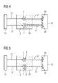
- FIG 4 schematically represents working of the technique when the metal 6 to be determined is not present in the oil sample 3
- FIG 5 schematically represents working of the technique when the metal 6 to be determined is present in the oil sample 3.
- the EM radiation 12 generated by the EM source 10 excites the QD 5 which in turn emits fluorescence in form of an electromagnetic signal 51 (hereinafter, signal 51) corresponding to the QD 5 that is detected by the detector 50 in form of the fluorescence spectrum 95 corresponding to the QD 5.
- the fluorescence spectrum 95 has a given signature such as an intensity of the signal 51 in absence of the metal 6.
- the EM radiation 12 generated by the EM source 10 excites the QD 5 which in turn emits fluorescence in form of an electromagnetic signal 52 (hereinafter, signal 52) corresponding to the QD 5 with attached metal 6.
- the signals 51, 52 are electromagnetic radiations having a particular wavelength.
- the fluorescence emitted by the QD 5 in presence of the metal 6 is quenched by occurrence of FRET.
- the EM signal 52 is detected by the detector 50 in form of or as a part of the fluorescence spectrum 95 corresponding to the QD 5 with attached metal 6.
- the fluorescence spectrum 95 in presence of the metal 6 has a different signature such as an intensity of the signal 52 as compared to the signature of the fluorescence spectrum 95 that includes the intensity of the signal 51 in absence of the metal 6. This difference is detected as a quenching in the fluorescence spectrum 95 corresponding to the QD 5.
- the quenching may be detected by comparing the signal 51 and the signal 52 and is defined to be present if the intensity of the signal 52 is lesser than the intensity of the signal 51.
- the metal 6 is determined by the quenching so determined in the fluorescence spectrum 95 corresponding to the QD 5.
- the signature of the fluorescence spectrum 95 including the intensity of the signal 51 in absence of the metal 6 may be previously known under a known set of physical conditions, i.e. as a standard or reference or control signature of the fluorescence spectrum 95, an occurrence or absence of the quenching in the fluorescence spectrum 95 corresponding to the QD 5 may be determined only by a single detection of the fluorescence spectrum 95 by the detector 50. Thus if on testing an unknown oil sample, the fluorescence spectrum 95 detected contains a substantially same signature as a previously known standard or reference or control signature of the fluorescence spectrum 95, then the metal 6 is determined to be not present in the oil sample 3.
- the signature of the fluorescence spectrum 95 including the intensity of the signal 52 in presence of the metal 6 may be previously known under a known set of physical conditions, i.e. as a positive standard signature of the fluorescence spectrum 95, and if on testing another unknown oil sample, the fluorescence spectrum 95 detected contains a substantially same signature as the previously known positive standard signature of the fluorescence spectrum 95, then the metal 6 is determined to be present in the oil sample 3.
- the processor 50 determines the occurrence or the absence of the quenching in the fluorescence spectrum 95 corresponding to the QD 5 and thereby determines the presence or the absence of the metal 6 in the oil sample 3.
- the processor 70 in the oil testing device 1 identifies the intensity of the EM signal 52 in the fluorescence spectrum 95 corresponding to the QD 5.
- the EM signal 52 corresponds to the QD 5 attached to the metal 6.
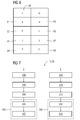
- the processor 70 compares the intensity so identified with a set 80 of reference intensities 81,82,83,84 as depicted in FIG 6 .
- the intensities 81,82,83,84 are tabulated under column 'I' in FIG 6 .
- Each of the reference intensities 81,82,83,84 in the set 80 corresponds to a unique concentration value 85,86,87,88 of the metal 6 in the oil sample 3.
- the concentration values 85,86,87,88 are tabulated under column 'C' in FIG 6 .
- the set 80 may be in form of a look-up table.
- the set 80 may be generated by testing different oil samples with varying known concentrations of the metal 6 using the QD 5 and storing the detected intensities against the different concentrations of the metal 6. These different detected intensities are used as the reference intensities 81,82,83,84.
- a concentration 'y' unit represented by reference numeral 87 corresponding to the 'c' unit 83 is determined to be the concentration of the metal 6 in the tested unknown oil sample.
- the present technique has been shown briefly for the determination of the additional metal 8 by the additional quantum dot 7 (hereinafter referred to as AQD 7) with the help of FIGs 1 to 5 .
- the determination of the additional metal 8 using the AQD 7 is similar to, and may be done simultaneously or successively with, the determination of the metal 6 using the QD 5 as explained above.
- the sample port 30 receives the AQD 7 which may be present in a suitable buffer solution same as or different from the buffer solution of the QD 5 and may be added to the sample port 30 simultaneously or successively with the QD 5 buffer solution and the oil sample 3.
- the AQD 7 in the oil sample 3 is excited by the EM radiation 12.
- a fluorescence spectrum 97 corresponding to the AQD 7 is detected at the detector 50.
- a quenching occurs when the additional metal 8 is present which is reflected in FIG 5 as compared to FIG 4 , i.e.
- the processor 70 determines a quenching in the fluorescence spectrum 97 corresponding to the AQD 7 and in turn the additional metal 8 is determined by the quenching so determined in the fluorescence spectrum 97 corresponding to the AQD 7 in a similar way as done for the determination of the metal 6 using the QD 5.
- the oil testing device 1 is enabled to determine a presence of the additional metal 8 in the oil sample 3.
- a concentration of the additional metal 8 may be determined using the AQD 7 in a similar way as done for the determination of the concentration of the metal 6 using the QD 5.
- the processor 70 in the oil testing device 1 identifies an additional intensity of the signal 72 in the fluorescence spectrum 97 corresponding to the AQD 7.
- the signal 72 corresponds to the AQD 7 attached to the additional metal 8.
- the processor 70 compares the additional intensity so identified with a set of additional reference intensities. Each of the additional reference intensities in the set corresponds to a unique concentration of the additional metal 8 in the oil sample 3.
- the determination of the metal 6 and the additional metal 8 may be done simultaneously in furtherance of which the detector 70 detects the fluorescence spectrum 95 corresponding to the QD 5 and the fluorescence spectrum 97 corresponding to the AQD 7 simultaneously.
- the QD 5 and the AQD 7 in the oil sample 3 are excited simultaneously using the EM radiation 12.
- the oil testing device 1 may be made portable and miniaturized in form.
- the miniature oil testing device 1 includes a fluid micro-channel etched on a substrate layer such as glass to function as the sample port 30, an input optical fiber is adapted to receive the EM radiation 12 from an EM source 10 and to direct the EM radiation 12 to the oil sample 3 and the QD 5 and/or the QD 7 in the oil sample 3, and an output optical fiber is adapted to receive the emitted signals 51,52,71,72 and to direct the emitted signals 51,52,71,72 to the detector 50.
- the processor detects the quenching in the fluorescence spectrums 95,97.
- FIG 7 represents a flow chart depicting an exemplary embodiment of an oil testing method 1000 (hereinafter the method 1000) for determination of at least one metal 6 in an oil sample 3, in accordance with aspects of the present technique.
- the QD 5 is added to the oil sample 3 in a step 100.
- the QD 5 in the oil sample 3 is excited by an EM radiation 12 incident on the oil sample 3.
- the fluorescence spectrum 95 corresponding to the QD 5 is detected in a step 300.
- the metal 6 is determined by observing the quenching in the fluorescence spectrum 95 corresponding to the QD 5.
- the method 1000 further includes a step 400 of determining the concentration of the metal 6 in the oil sample 3.
- the intensity of the signal 52 in the fluorescence spectrum 95 corresponding to the QD 5 is identified in a step 420.
- the intensity so identified is compared with the set 80 of the reference intensities 81,82,83,84 and the concentration of the metal 6 in the oil sample 3 is determined as explained in reference to FIG 6 .
- the method 1000 further includes a step 500 of determining the additional metal 8 in the oil sample 3.
- FIG 7 depicts the step 500 as simultaneously performed with steps 100 to step 400, it may be noted that the step 500 may be successively, either before or after, performed with the steps 100 to 400.
- the AQD 7 is added to the oil sample 3 in a step 510.
- the AQD 7 in the oil sample 3 is excited by the EM radiation 12 incident on the oil sample 3 in a step 520.
- the fluorescence spectrum 97 corresponding to the AQD 7 is detected in a step 530.
- the additional metal 8 is determined by observing the quenching in the fluorescence spectrum 97 corresponding to the AQD 7.
- the method 1000 includes a step 540 of determining the concentration of the additional metal 8 in the oil sample 3.
- the additional intensity of the signal 72 in the fluorescence spectrum 97 corresponding to the AQD 7 is identified in a step 542.
- the signal 72 corresponds to the AQD 7 attached with the additional metal 8.
- the additional intensity so identified is compared with a set of additional reference intensities and thereby the concentration of the additional metal 8 in the oil sample 3 is determined in a way similar to the way of determining the concentration of the metal 6 as explained in reference to FIG 6 .
Landscapes
- Health & Medical Sciences (AREA)
- Chemical & Material Sciences (AREA)
- Life Sciences & Earth Sciences (AREA)
- Immunology (AREA)
- Physics & Mathematics (AREA)
- Analytical Chemistry (AREA)
- Pathology (AREA)
- Engineering & Computer Science (AREA)
- General Physics & Mathematics (AREA)
- General Health & Medical Sciences (AREA)
- Biochemistry (AREA)
- Chemical Kinetics & Catalysis (AREA)
- General Chemical & Material Sciences (AREA)
- Medicinal Chemistry (AREA)
- Food Science & Technology (AREA)
- Oil, Petroleum & Natural Gas (AREA)
- Nuclear Medicine, Radiotherapy & Molecular Imaging (AREA)
- Molecular Biology (AREA)
- Optics & Photonics (AREA)
- Investigating, Analyzing Materials By Fluorescence Or Luminescence (AREA)
Priority Applications (1)
| Application Number | Priority Date | Filing Date | Title |
|---|---|---|---|
| EP13185938.1A EP2853884A1 (de) | 2013-09-25 | 2013-09-25 | Verfahren zur Bestimmung von Metallen in Ölproben aus Schmieröl von Maschinen |
Applications Claiming Priority (1)
| Application Number | Priority Date | Filing Date | Title |
|---|---|---|---|
| EP13185938.1A EP2853884A1 (de) | 2013-09-25 | 2013-09-25 | Verfahren zur Bestimmung von Metallen in Ölproben aus Schmieröl von Maschinen |
Publications (1)
| Publication Number | Publication Date |
|---|---|
| EP2853884A1 true EP2853884A1 (de) | 2015-04-01 |
Family
ID=49237080
Family Applications (1)
| Application Number | Title | Priority Date | Filing Date |
|---|---|---|---|
| EP13185938.1A Withdrawn EP2853884A1 (de) | 2013-09-25 | 2013-09-25 | Verfahren zur Bestimmung von Metallen in Ölproben aus Schmieröl von Maschinen |
Country Status (1)
| Country | Link |
|---|---|
| EP (1) | EP2853884A1 (de) |
Cited By (4)
| Publication number | Priority date | Publication date | Assignee | Title |
|---|---|---|---|---|
| WO2016184744A1 (fr) * | 2015-05-21 | 2016-11-24 | IFP Energies Nouvelles | Systeme de mesure de la quantite de nano-cristaux semi-conducteurs presents dans un fluide |
| WO2016174356A3 (fr) * | 2015-04-30 | 2016-12-29 | bioMérieux | Machine et procédé pour la détection automatisée in vitro d'analytes mettant en ouvre une décomposition spectrale chromatique d'une réponse optique |
| CN114460048A (zh) * | 2020-11-09 | 2022-05-10 | 中国科学院大连化学物理研究所 | 钙钛矿量子点荧光淬灭法测定食用油中极性物质的质量含量的方法 |
| CN117859950A (zh) * | 2023-11-29 | 2024-04-12 | 张家口卷烟厂有限责任公司 | 卷烟油烟快速鉴别方法 |
Citations (4)
| Publication number | Priority date | Publication date | Assignee | Title |
|---|---|---|---|---|
| US5308773A (en) * | 1992-11-16 | 1994-05-03 | Microbiomed Corp. | Non-azo 1,8-naphthalimide dyes for the detection and quantitation of a paramagnetic metal cation in a non-aqueous medium |
| US20050227369A1 (en) * | 2004-04-13 | 2005-10-13 | The Lubrizol Corporation, A Corporation Of The State Of Ohio | Rapid analysis of functional fluids |
| US20090200486A1 (en) * | 2008-02-13 | 2009-08-13 | Nianqiang Wu | Quantum dot-DNA-metallic nanoparticle ensemble as fluorescent nanosensor system for multiplexed detection of heavy metals |
| US20120070852A1 (en) * | 2008-12-01 | 2012-03-22 | Imperial Innovations Limited | Assay |
-
2013
- 2013-09-25 EP EP13185938.1A patent/EP2853884A1/de not_active Withdrawn
Patent Citations (4)
| Publication number | Priority date | Publication date | Assignee | Title |
|---|---|---|---|---|
| US5308773A (en) * | 1992-11-16 | 1994-05-03 | Microbiomed Corp. | Non-azo 1,8-naphthalimide dyes for the detection and quantitation of a paramagnetic metal cation in a non-aqueous medium |
| US20050227369A1 (en) * | 2004-04-13 | 2005-10-13 | The Lubrizol Corporation, A Corporation Of The State Of Ohio | Rapid analysis of functional fluids |
| US20090200486A1 (en) * | 2008-02-13 | 2009-08-13 | Nianqiang Wu | Quantum dot-DNA-metallic nanoparticle ensemble as fluorescent nanosensor system for multiplexed detection of heavy metals |
| US20120070852A1 (en) * | 2008-12-01 | 2012-03-22 | Imperial Innovations Limited | Assay |
Non-Patent Citations (2)
| Title |
|---|
| LI H ET AL: "Single quantum dot-micelles coated with gemini surfactant for selective recognition of a cation and an anion in aqueous solutions", SENSORS AND ACTUATORS B: CHEMICAL: INTERNATIONAL JOURNAL DEVOTED TO RESEARCH AND DEVELOPMENT OF PHYSICAL AND CHEMICAL TRANSDUCERS, ELSEVIER S.A, CH, vol. 134, no. 1, 28 August 2008 (2008-08-28), pages 238 - 244, XP023979352, ISSN: 0925-4005, [retrieved on 20080502], DOI: 10.1016/J.SNB.2008.04.041 * |
| LIZHOU XU ET AL: "Identification of adulterated vegetable cooking oils using fluorescence quenching method with aqueous CTAB-coated CdSe/ZnS quantum dots as probes", 2013 IEEE SENSORS, 3 November 2013 (2013-11-03) - 6 November 2013 (2013-11-06), pages 1 - 4, XP055104759, ISBN: 978-1-46-734642-9, DOI: 10.1109/ICSENS.2013.6688226 * |
Cited By (12)
| Publication number | Priority date | Publication date | Assignee | Title |
|---|---|---|---|---|
| WO2016174356A3 (fr) * | 2015-04-30 | 2016-12-29 | bioMérieux | Machine et procédé pour la détection automatisée in vitro d'analytes mettant en ouvre une décomposition spectrale chromatique d'une réponse optique |
| CN107533007A (zh) * | 2015-04-30 | 2018-01-02 | 生物梅里埃公司 | 借助于光学响应的彩色光谱分解进行体外自动分析物检测的机器和方法 |
| US10753926B2 (en) | 2015-04-30 | 2020-08-25 | bioMérieux | Machine and method for automated in vitro analyte detection by means of chromatic spectral decomposition of an optical response |
| JP2021099347A (ja) * | 2015-04-30 | 2021-07-01 | ビオメリューBiomerieux | 光応答の色スペクトル分解を用いた自動インビトロ検体検出のための装置及び方法 |
| CN107533007B (zh) * | 2015-04-30 | 2024-03-19 | 生物梅里埃公司 | 借助于光学响应的彩色光谱分解进行体外自动分析物检测的机器和方法 |
| WO2016184744A1 (fr) * | 2015-05-21 | 2016-11-24 | IFP Energies Nouvelles | Systeme de mesure de la quantite de nano-cristaux semi-conducteurs presents dans un fluide |
| FR3036492A1 (fr) * | 2015-05-21 | 2016-11-25 | Ifp Energies Now | Systeme de mesure de la quantite de nano-cristaux semi-conducteurs presents dans un fluide |
| US10495577B2 (en) | 2015-05-21 | 2019-12-03 | IFP Energies Nouvelles | System for measuring the quantity of semiconductor nanocrystals present in a fluid |
| CN114460048A (zh) * | 2020-11-09 | 2022-05-10 | 中国科学院大连化学物理研究所 | 钙钛矿量子点荧光淬灭法测定食用油中极性物质的质量含量的方法 |
| CN114460048B (zh) * | 2020-11-09 | 2024-03-22 | 中国科学院大连化学物理研究所 | 钙钛矿量子点荧光淬灭法测定食用油中极性物质的质量含量的方法 |
| CN117859950A (zh) * | 2023-11-29 | 2024-04-12 | 张家口卷烟厂有限责任公司 | 卷烟油烟快速鉴别方法 |
| CN117859950B (zh) * | 2023-11-29 | 2026-04-21 | 张家口卷烟厂有限责任公司 | 卷烟油烟快速鉴别方法 |
Similar Documents
| Publication | Publication Date | Title |
|---|---|---|
| Jones et al. | Standard dilution analysis | |
| US6801595B2 (en) | X-ray fluorescence combined with laser induced photon spectroscopy | |
| ATE308038T1 (de) | Fluorimeter für immunoassay | |
| EP2853884A1 (de) | Verfahren zur Bestimmung von Metallen in Ölproben aus Schmieröl von Maschinen | |
| Hao et al. | One-point and multi-line calibration method in laser-induced breakdown spectroscopy | |
| EP3701235B1 (de) | Detektionssystem für fluoreszente substanz | |
| US10281448B2 (en) | Determining the deterioration of oils using fluorescence rise-time | |
| JP2019504315A5 (de) | ||
| Chizhik et al. | Quantum yield measurement in a multicolor chromophore solution using a nanocavity | |
| Melikechi et al. | Blood metal analysis of plasmas from donors with and without SARS-CoV-2 using laser-induced breakdown spectroscopy and logistic regression | |
| CN104730043A (zh) | 一种基于偏最小二乘法的墨水中重金属测定方法 | |
| JPH0862207A (ja) | 潤滑油の劣化検知方法 | |
| US20090273778A1 (en) | Surface enhanced resonant raman spectroscopy | |
| Zhang et al. | Simple and accurate quantification of quantum dots via single-particle counting | |
| EP3194914B1 (de) | Normalisierung der reaktion eines fluoreszenzinstruments mit spektraler reaktion | |
| Guenard et al. | Two-channel sequential single-molecule measurement | |
| Gallian et al. | A compact time-gated instrument for QDs with low excitation energy and millisecond fluorescence lifetime as signal reporters, and its detection application | |
| Xu et al. | Joint Statistical Analysis of Multichannel Time Series from Single Quantum Dot−(Cy5) n Constructs | |
| Fang et al. | Direct imaging of single gold and polystyrene nanoparticles in the deep ultraviolet | |
| Ahern et al. | Luminescence based fiber optic probe for the detection of rare earth elements | |
| US20220236170A1 (en) | Measurement of dissolved oxygen using optical radiation induced luminescence | |
| CN112666103A (zh) | 基于光谱特征的水质监测系统 | |
| JP2006023092A (ja) | 分析方法およびその装置 | |
| Zhong et al. | A LED-induced confocal fluorescence detection system for quantitative PCR instruments | |
| JP2018009912A (ja) | クーラント分析方法、クーラント分析システム及びクーラント分析装置 |
Legal Events
| Date | Code | Title | Description |
|---|---|---|---|
| PUAI | Public reference made under article 153(3) epc to a published international application that has entered the european phase |
Free format text: ORIGINAL CODE: 0009012 |
|
| 17P | Request for examination filed |
Effective date: 20130925 |
|
| AK | Designated contracting states |
Kind code of ref document: A1 Designated state(s): AL AT BE BG CH CY CZ DE DK EE ES FI FR GB GR HR HU IE IS IT LI LT LU LV MC MK MT NL NO PL PT RO RS SE SI SK SM TR |
|
| AX | Request for extension of the european patent |
Extension state: BA ME |
|
| STAA | Information on the status of an ep patent application or granted ep patent |
Free format text: STATUS: THE APPLICATION IS DEEMED TO BE WITHDRAWN |
|
| 18D | Application deemed to be withdrawn |
Effective date: 20151002 |