EP2853915B1 - Radarvorrichtung und winkelüberprüfungsverfahren - Google Patents
Radarvorrichtung und winkelüberprüfungsverfahren Download PDFInfo
- Publication number
- EP2853915B1 EP2853915B1 EP12877198.7A EP12877198A EP2853915B1 EP 2853915 B1 EP2853915 B1 EP 2853915B1 EP 12877198 A EP12877198 A EP 12877198A EP 2853915 B1 EP2853915 B1 EP 2853915B1
- Authority
- EP
- European Patent Office
- Prior art keywords
- amplitude
- phase
- antennas
- angle
- unit
- Prior art date
- Legal status (The legal status is an assumption and is not a legal conclusion. Google has not performed a legal analysis and makes no representation as to the accuracy of the status listed.)
- Active
Links
Images





Classifications
-
- G—PHYSICS
- G01—MEASURING; TESTING
- G01S—RADIO DIRECTION-FINDING; RADIO NAVIGATION; DETERMINING DISTANCE OR VELOCITY BY USE OF RADIO WAVES; LOCATING OR PRESENCE-DETECTING BY USE OF THE REFLECTION OR RERADIATION OF RADIO WAVES; ANALOGOUS ARRANGEMENTS USING OTHER WAVES
- G01S13/00—Systems using the reflection or reradiation of radio waves, e.g. radar systems; Analogous systems using reflection or reradiation of waves whose nature or wavelength is irrelevant or unspecified
- G01S13/02—Systems using reflection of radio waves, e.g. primary radar systems; Analogous systems
- G01S13/06—Systems determining position data of a target
- G01S13/42—Simultaneous measurement of distance and other co-ordinates
-
- G—PHYSICS
- G01—MEASURING; TESTING
- G01S—RADIO DIRECTION-FINDING; RADIO NAVIGATION; DETERMINING DISTANCE OR VELOCITY BY USE OF RADIO WAVES; LOCATING OR PRESENCE-DETECTING BY USE OF THE REFLECTION OR RERADIATION OF RADIO WAVES; ANALOGOUS ARRANGEMENTS USING OTHER WAVES
- G01S13/00—Systems using the reflection or reradiation of radio waves, e.g. radar systems; Analogous systems using reflection or reradiation of waves whose nature or wavelength is irrelevant or unspecified
- G01S13/88—Radar or analogous systems specially adapted for specific applications
- G01S13/93—Radar or analogous systems specially adapted for specific applications for anti-collision purposes
- G01S13/931—Radar or analogous systems specially adapted for specific applications for anti-collision purposes of land vehicles
-
- G—PHYSICS
- G01—MEASURING; TESTING
- G01S—RADIO DIRECTION-FINDING; RADIO NAVIGATION; DETERMINING DISTANCE OR VELOCITY BY USE OF RADIO WAVES; LOCATING OR PRESENCE-DETECTING BY USE OF THE REFLECTION OR RERADIATION OF RADIO WAVES; ANALOGOUS ARRANGEMENTS USING OTHER WAVES
- G01S3/00—Direction-finders for determining the direction from which infrasonic, sonic, ultrasonic or electromagnetic waves, or particle emission, not having a directional significance, are being received
- G01S3/02—Direction-finders for determining the direction from which infrasonic, sonic, ultrasonic or electromagnetic waves, or particle emission, not having a directional significance, are being received using radio waves
- G01S3/74—Multi-channel systems specially adapted for direction-finding, i.e. having a single antenna system capable of giving simultaneous indications of the directions of different signals
-
- G—PHYSICS
- G01—MEASURING; TESTING
- G01S—RADIO DIRECTION-FINDING; RADIO NAVIGATION; DETERMINING DISTANCE OR VELOCITY BY USE OF RADIO WAVES; LOCATING OR PRESENCE-DETECTING BY USE OF THE REFLECTION OR RERADIATION OF RADIO WAVES; ANALOGOUS ARRANGEMENTS USING OTHER WAVES
- G01S13/00—Systems using the reflection or reradiation of radio waves, e.g. radar systems; Analogous systems using reflection or reradiation of waves whose nature or wavelength is irrelevant or unspecified
- G01S13/88—Radar or analogous systems specially adapted for specific applications
- G01S13/93—Radar or analogous systems specially adapted for specific applications for anti-collision purposes
- G01S13/931—Radar or analogous systems specially adapted for specific applications for anti-collision purposes of land vehicles
- G01S2013/93185—Controlling the brakes
-
- G—PHYSICS
- G01—MEASURING; TESTING
- G01S—RADIO DIRECTION-FINDING; RADIO NAVIGATION; DETERMINING DISTANCE OR VELOCITY BY USE OF RADIO WAVES; LOCATING OR PRESENCE-DETECTING BY USE OF THE REFLECTION OR RERADIATION OF RADIO WAVES; ANALOGOUS ARRANGEMENTS USING OTHER WAVES
- G01S13/00—Systems using the reflection or reradiation of radio waves, e.g. radar systems; Analogous systems using reflection or reradiation of waves whose nature or wavelength is irrelevant or unspecified
- G01S13/88—Radar or analogous systems specially adapted for specific applications
- G01S13/93—Radar or analogous systems specially adapted for specific applications for anti-collision purposes
- G01S13/931—Radar or analogous systems specially adapted for specific applications for anti-collision purposes of land vehicles
- G01S2013/9327—Sensor installation details
- G01S2013/93271—Sensor installation details in the front of the vehicles
-
- G—PHYSICS
- G01—MEASURING; TESTING
- G01S—RADIO DIRECTION-FINDING; RADIO NAVIGATION; DETERMINING DISTANCE OR VELOCITY BY USE OF RADIO WAVES; LOCATING OR PRESENCE-DETECTING BY USE OF THE REFLECTION OR RERADIATION OF RADIO WAVES; ANALOGOUS ARRANGEMENTS USING OTHER WAVES
- G01S7/00—Details of systems according to groups G01S13/00, G01S15/00, G01S17/00
- G01S7/02—Details of systems according to groups G01S13/00, G01S15/00, G01S17/00 of systems according to group G01S13/00
- G01S7/35—Details of non-pulse systems
- G01S7/352—Receivers
- G01S7/354—Extracting wanted echo-signals
Definitions
- the present invention relates to a radar apparatus that receives a reflected wave reflected by a target object by an antenna to detect the direction of the target object.
- a vehicle uses information about a target object detected by an in-vehicle radar apparatus, to perform drive support by having various in-vehicle devices cooperate for avoiding an obstacle, and to control the vehicle speed and the distance to a preceding vehicle to travel while following the preceding vehicle.
- the radar apparatus irradiates, for example, a millimeter wave to a predetermined range in front of the vehicle, and receives a reflected wave reflected by a target in the irradiation range. Then, by analyzing the reception wave, the distance, relative speed, and direction (angle or lateral position) to the target are detected.
- a radio wave such as a millimeter wave is reflected by an object other than the preceding vehicle or the detection target, such as a wall, a road surface, and a manhole, and hence, the reflected wave is received via a what-is-called "multipath".
- the radio wave is reflected by a sidewall of the tunnel, which makes the vehicle detect a target on the sidewall side in front.
- a target detected by a reception wave received after being reflected by a wall is called a "mirror ghost".
- Patent Document 1 discloses a radar apparatus that sets a virtual wall beside a detected target to detect a mirror ghost based on the speed of another target symmetrically positioned with the target with respect to the virtual wall.
- FIG. 1 is an example of diagrams illustrating a problem with a conventional radar apparatus.
- the radar apparatus of a vehicle separately detects a preceding vehicle and another target (mirror ghost) symmetrically positioned with respect to a virtual wall. Therefore, it is possible to detect that a reception wave reflected by the wall is not from the target, but from the mirror ghost.
- the radar apparatus of the vehicle detects a target about an intermediate point between the preceding vehicle and the mirror ghost.
- Such inconvenience tends to occur when the space between the preceding vehicle and the wall is narrow; the distance between the vehicle and the preceding vehicle is great; or, an angle formed between the direction of the mirror ghost and the direction of the preceding vehicle is small when viewed from the vehicle.
- the radar apparatus detects that a target is positioned in an intermediate direction (on the virtual wall) between the preceding vehicle and the mirror ghost. Consequently, the target itself is detected, but its direction is shifted.
- the conventional radar apparatus has the problem in that it cannot distinguish a preceding vehicle from a mirror ghost, depending on a relative positional relationship among the preceding vehicle, the virtual wall, and the vehicle.
- Patent Document 1 Japanese Laid-open Patent Publication No. 2009-133761
- US 2008/0297402 A1 as the next-coming prior art discloses an array antenna calibration verification coupling an interrogator and a responder with a mode-related interrogation signal having a previous calibration phase angle.
- a characteristic interrogation response and a characteristic conjugate response generated by reversing phase of interrogation signal are produced in order to be sensed and combined to determine difference characteristic for responder array elements in antenna array representative of a present calibration verification state.
- Present and previous calibration verification states are compared, and if a significant variation is found, the array antenna may be adapted to a desired calibration verification state.
- a radar apparatus configured to receive a transmission wave reflected by a target object by a plurality of antennas, includes a signal analysis unit configured to analyze reception waves received by the respective antennas, and to obtain an amplitude and a phase of each of the reception waves received at the respective antennas, the amplitude and the phase being obtained at a frequency with which a reception strength shows a peak; a direction detection unit configured to detect a direction of the target object based on the phases of the reception waves received by the respective antennas; an estimated amplitude and phase output unit configured to output an estimated amplitude and an estimated phase of each of reception waves to be received by the respective antennas, assuming that the target object exists in the direction detected by the direction detection unit; and a comparison unit configured to compare at least one of the amplitudes and the phases for each of the antennas such that the amplitude obtained by the signal analysis unit is compared with the amplitude
- a radar apparatus that can detect a reception wave coming from a target object possibly including radio waves in multiple directions.
- FIG. 2 is an example of diagrams illustrating general features of a radar apparatus according to an embodiment of the present embodiment. As described above, there are cases where a radar apparatus cannot separate a radio wave reflected by a wall in a tunnel or the like, from a radio wave reflected by a preceding vehicle. Although the preceding vehicle should be detected in the front direction in an example in the figure, a target is detected at an angle ⁇ .
- the radar apparatus determines whether a target (a mirror ghost in this case) exists in the direction at the measured angle ⁇ , or the target is not separated due to a multipath as follows.
- the radar apparatus in the present embodiment can prevent detection precision of the lateral position of a preceding vehicle from being reduced when a multipath is generated in a tunnel that makes a target unseparable.
- the present embodiment focuses on a multipath from a preceding vehicle and a wall (or a ceiling surface) of a tunnel, it is favorably applicable to a situation where multiple reception waves cannot be separated because the multiple reception waves come in close directions, regardless of an existence of a multipath. Also, it is applicable to any moving objects or fixed objects as long as they can reflect a millimeter wave.
- a reflecting object of a radar is called a "target object” in general, a reflection source of a multipath and a preceding vehicle may not be distinguished, and called a “target” in the present embodiment.
- an angle ⁇ at which a target is detected may be called a "direction”, an “azimuth”, or a “lateral position”, it is consistently called an "angle” in the present embodiment.
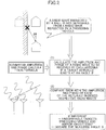
- FIG. 3 is an example of diagrams schematically illustrating steps to detect the distance and direction to a target executed by a radar apparatus.
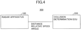
- FIG. 4 is an example of a configuration diagram illustrating an in-vehicle system 300 that includes a radar apparatus and a collision determination ECU.
- the radar apparatus 100 and the collision determination ECU (Electronic Control Unit) 200 are connected with each other via an in-vehicle LAN, for example, a CAN (Controller Area Network).
- the radar apparatus 100 is disposed at a center portion in the front of the vehicle, for example, a front grill of the vehicle, to irradiate a millimeter wave in a predetermined angle centered around the front of the vehicle (for example, left and right 10° centered around the front), and to receive a reflected wave reflected by a target existing in this range.
- the radar apparatus 100 is, for example, an FMCW (Frequency Modulated Continuous Wave) radar.
- FMCW Frequency Modulated Continuous Wave
- the radar apparatus 100 periodically outputs the distance, relative speed, and angle to every target to the collision determination unit 200.
- the collision determination unit 200 calculates the TTC (Time To Collision) for each of the targets from the distance and relative speed. Then, it identifies a target that has a smallest TTC among targets having angles below a predetermined value that indicates closeness to the vehicle, and if the TTC becomes less than or equal to a threshold, it executes drive supports such as displaying an alarm on a meter panel, blowing an alarm sound, and/or executing automatic braking. Also, another ECU may execute traveling control to follow a preceding vehicle by adjusting the distance to the preceding vehicle depending on the vehicle speed.
- TTC Time To Collision
- FIG. 5 is an example of a general configuration diagram of the radar apparatus 100.
- the radar apparatus 100 includes a transmission antenna 11, n (n ⁇ 2) units of reception antennas 12, switches 17 to connect or disconnect the respective reception antennas 12 and mixers 14, a signal oscillator 13, the mixers 14, an A/D converter 15, and a signal analysis unit 16.
- the signal oscillator 13 generates a high-frequency signal in a millimeter wave band.
- the signal oscillator 13 can change the frequency of the high-frequency signal to be generated by control of the signal analysis unit 16.
- the transmission antenna 11 transmits a radar wave (transmission wave) corresponding to the high-frequency signal generated by the signal oscillator 13 within a predetermined angle range.
- the reception antennas 12 receive the radar wave (reflected wave) reflected by a target.
- the reception antennas 12 always receive the reflected wave, and the switches 17 selectively connect one of the reception antennas 12 with the corresponding mixer 14. States of the switches 17 are controlled by the signal analysis unit 16.
- Each of the mixers 14 generates a beat signal by mixing the transmission wave and the reception wave, and outputs it to the A/D converter circuit 15.
- the A/D converter 15 applies A/D conversion to the beat signal, and outputs it to the signal analysis unit 16.
- the signal analysis unit 16 is a microcomputer including a CPU, a ROM, a RAM, and the like, and also includes an I/O, a DSP, a CAN controller, and the like (not illustrated).
- the signal analysis unit 16 repeats bringing up and down the frequency generated by the signal oscillator 13, analyzes the beat signal, and calculates the distance, relative speed, and angle to the target.
- FIG. 6 is an example of a functional block diagram schematically illustrating the signal analysis unit 16.
- the signal analysis unit 16 includes a transmission wave control unit 21, an FFT unit 22, an angle detection unit 23, and an angle verification unit 24.
- the beat signal will be described. Only one of the switches 17 between the reception antennas 12 and the mixers 14 is turned on at a certain moment. Therefore, a transmission wave transmitted by the transmission antenna 11 and reflected by a target is received by the reception antennas 12 in a time-sharing manner to obtain a beat signal with each of the reception antennas 12.
- the frequency of a beat signal is called a "beat frequency”.
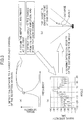
- FIG. 7 is an example of diagrams illustrating a beat frequency.
- the transmission wave control unit 21 controls the frequency of the signal oscillator 13 to make it repeatedly changed to have a linearly rising interval for a predetermined ratio in terms of time (this interval is called a "rise interval"), followed by a linearly falling interval for the predetermined ratio (this interval is called a "fall interval”).
- the frequency of the transmission wave is increased by ⁇ F and decreased by ⁇ F within a duration of 1/fm.
- the center frequency is f 0 .
- the transmission wave control unit 21 controls to repeat the increase and decrease of the frequency for every predetermined cycle (for example, 100 ms). Note that although the frequency is stable for a certain interval in the figure, the frequency may be constantly increased and decreased.
- the transmission wave returns to the vehicle as a reflected wave.
- the reception antennas 12 of the radar apparatus 100 receive this reflected wave, respectively.
- fb 1 represents the beat frequency of a rise interval
- fb 2 represents the beat frequency of a fall interval
- fr represents the beat frequency when the relative speed is zero
- fd represents a Doppler frequency (increased or decreased amount) when the relative speed is not zero.
- the beat frequency fb 1 of the rise interval is a value obtained by subtracting the Doppler frequency fd from the beat frequency fr at the relative speed of zero
- the beat frequency fb 2 of the fall interval is a value obtained by adding the Doppler frequency fd to the beat frequency fr at the relative speed of zero.
- R C / 4 ⁇ ⁇ F ⁇ fm ⁇ fr
- V C / 2 ⁇ f 0 ⁇ fd
- the reception waves received by the reception antennas 12 include waves having various frequencies, amplitudes, and phases due to an influence of a multipath and the like. Therefore, the FFT unit 22 applies a Fourier transform to the beat signal to extract only the beat signal from the reception wave received by the reception antennas 12. Thus, fb 1 and fb 2 can be extracted from the beat signal.
- the FFT unit 22 applies the Fourier transform to the beat signal in the rise interval and the fall interval, respectively.
- wave components having multiple frequencies are obtained.
- a wave is represented by a complex vector.
- the result of the Fourier transform is represented by F (i indicates an imaginary number) as follows.
- F ⁇ a n ⁇ cos nwt + i ⁇ b n ⁇ sin nwt
- the signal strength takes a peak at frequencies corresponding to fb 1 and fb 2 because the signal strength is high at frequencies included in the signal.
- peaks of the signal strengths are obtained with respect to frequencies of the respective antennas.
- results of the Fourier transform in FIG. 6 show a single peak, multiple peaks may exist if multiple targets exist.
- peaks are obtained in the rise interval and the fall interval, respectively.
- the peak frequency detected from the reception wave in the rise interval is fb 1
- the peak frequency detected from the reception wave in the fall interval is fb 2 .
- the position of the peak may be estimated by calculating change of power P with respect to the frequency, and assuming that a peak exists at a frequency where the power P is changed from increasing to decreasing. Also, to reduce side lobes included in a calculation result of the Fourier transform, a known window process is applied using a window function.
- the FFT unit 22 extracts the amplitude and phase of the reception wave at the frequency where the power takes the peak for each of the reception antennas.
- the amplitude can be treated as the power P, which is obtained as follows. Note that a subscript of "p" means a frequency where the power takes a peak.
- P w ⁇ a p 2 + b p 2
- phase relative to the real axis is obtained by the next formula.
- ⁇ p tan ⁇ 1 a p / b p
- the angle detection unit 23 calculates the angle of the target from the amplitudes and phases obtained from the peak frequencies of the beat signals received by the respective reception antennas 12.
- a phase difference is generated between the reception antennas 12 depending on the angle.
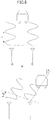
- FIG. 8(a) is an example of a diagram illustrating a phase difference between reception waves received by adjacent reception antennas 12 when a target is in front
- FIG. 8(b) is an example of a diagram illustrating a phase difference between reception waves received by the adjacent reception antennas 12 when the target is positioned at an angle.
- the angle ⁇ can be calculated once the phases are obtained because the placement interval of the radio wave reception antennas 12 and the wavelength are fixed.
- the phase of a reception wave can be obtained by the DBF process that implements a concept of phased array antennas in a digital process.
- a phase shifter to shift the phase of a radio wave is disposed at the following stage of each of the reception antennas 12, to control the shift amount of each of the reception antennas 12 depending on the angle to a target.
- the directivity is oriented in the direction ⁇ .
- the DBF process realizes this process by a digital circuit such as a DSP.
- the DBF process samples a reception signal at a frequency sufficiently greater than a beat frequency for one or more cycles.
- the beat frequency is a frequency generated by a slight difference between frequencies of a transmission wave in a millimeter wave band and a reception wave. Therefore, the frequency of the beat frequency is lower than that of the millimeter wave in an order of magnitude. If the frequency of the millimeter wave is several dozen GHz, the frequency of the beat frequency is less than several hundred kHz.
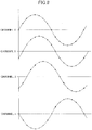
- FIG. 9 is an example of a conceptual diagram illustrating sampling. Depending on angles to a target, phase differences are generated in channels 1 to n. By sampling data of beat signals for one or more cycles, the phases received by the respective reception antennas 1 to n can be recorded in reception buffers. In the figure, a black-circled point is a sampling point.
- a beat signal once a beat signal is taken in, it can be used to form a beam in an arbitrary direction to detect a target. Namely, by changing ⁇ with a predetermined resolution (for example, 0.5°), it controls data to be read out from the reception buffer to be added. Similarly to phased array antennas, the added result of the data should be a maximal at an angle corresponding to the direction where the target exists.
- a predetermined resolution for example, 0.5°
- FIG. 3(b) The added results (power) with respect to the angle ⁇ are plotted as illustrated in FIG. 3(b) .
- the added results are illustrated as power.
- FIG. 3(b) is for a case of only one target, and there is one outstanding peak. Other peaks correspond to side lobes. By searching for peaks greater than or equal to a threshold, the angle to the target can be identified (3° rightward relative to the front direction in the figure).
- the MUSIC analysis is a method that forms a matrix having analysis results of beat signals arrayed, and uses an eigenvalue correlation. It will be briefly described. From results of the Fourier transform applied to a rise interval and a fall interval, respectively, the amplitudes and phases of the reception antennas 12 at a peak frequency of the power are arrayed to generate vectors. Then, an autocorrelation matrix is obtained from these vectors, and eigenvalues of the autocorrelation matrix are obtained. It is considered that the number of eigenvalues correlates to the number of independent reception waves. From the eigenvalues and steering vectors of the angle ⁇ , a MUSIC spectrum can be obtained.
- the mono-pulse method is a method that calculates sums, differences, power ratios, and phase differences of reception signals received by reception antennas based on an antenna pattern, and detects the directional angle of a target from the calculation results.
- the angle verification unit 24 verifies whether the angle to the target detected by the angle detection unit 23 is correct (whether there exist reception waves that are not separated).
- the angle of a target detected by the angle detection unit 23 is referred to as a "measured angle”.
- the angle verification unit 24 stores the estimated amplitude and phase calculation formula beforehand.
- the estimated amplitude and phase calculation formula is a formula to calculate an amplitude and a phase of a reception wave estimated for each channel from a measured angle, which will be described in detail below.
- the radar apparatus 100 can detect the measured angle of a target, there are cases where it is difficult to separate and detect a target when multiple targets exist in a narrow range as represented by a mirror ghost described above.
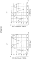
- FIG. 10 is an example of diagrams illustrating where identification of the directions of targets is difficult.
- FIG. 10(a) illustrates a calculation result of angles detected by the angle detection unit 23 when two targets actually exist. There are two peaks of the signal strength greater than or equal to a threshold (for example, 0 dB), and the angles are about -3.5° and +10°, respectively. These angles are substantially the same as the directions in which the targets actually exist. This is an example where an angle calculation is appropriately performed.
- a threshold for example, 0 dB
- FIG. 10(b) illustrates a calculation result of angles detected when three targets actually exist. Three targets exist at angles of - 5°, -2°, and +10°, respectively. However, comparing FIG. 10(b) with FIG. 10(a) , it can be understood that results of the angle calculations look alike. Namely, both FIG. 10(a) and (b) have peaks at +10°, and hence, the targets at +10° are detected. However, a peak appears around -3.5° in FIG. 10(b) , similarly to FIG. 10(a) . This happens because the radar apparatus 100 cannot separate a radio wave coming in -5° from a radio wave coming in -2°, based on the calculation result of angles in FIG. 10(b) .
- Such a state in which two radio waves having little difference in angles reach the radar apparatus 100, may be generated in a tunnel or the like when a radio wave is reflected by a preceding vehicle, and the radio wave reflected by the preceding vehicle is reflected again by a tunnel wall.
- the mirror ghost is a target that appears as if existing in an extended direction of a reception wave received after being reflected by the tunnel wall after having been reflected by the preceding vehicle.
- the angle (lateral position) of the preceding vehicle that has been captured by the radar apparatus 100 is changed to an intermediate position between the preceding vehicle and the mirror ghost, for example, soon after entering into a tunnel.
- the preceding vehicle is recognized as if it moves sideways (for example, moves closer to an adjacent lane for a lane change).
- the radar apparatus 100 in the present embodiment detects that the arrived waves are not separated, by using data of the amplitudes and phases of the waves received by the reception antennas 12.
- the amplitude and phase data used for obtaining an angle is not the same for a single-target case and for a multiple-target case even if calculation results of angles are the same, such as targets at the angle of -3.5° in FIG. 10(a) and (b) .
- FIG. 11 is an example of diagrams illustrating comparison between the amplitudes or the phases of the reception antennas when targets are positioned at the angles of about -3.5° and +10°, and at the angles of -5°, -2°, and 10°.
- the horizontal axes in FIG. 11 represent channel numbers (reception antennas).
- the vertical axes in the upper row represent the amplitude ratios of the amplitude of the channel number 1 to the amplitudes of the other channels, and the vertical axes in the lower row represent the phase differences of the phase of the channel number 1 to the phases of the other channels. Therefore, in both the separable state and the hardly-separable state, the amplitude ratio of the channel 1 is "1", and the phase difference of the channel 1 is "0°".
- the separable state and the hardly-separable state are compared in terms of the amplitude ratios.
- the separable state and the hardly-separable state are compared in terms of the phase differences.
- the angle detection unit 23 when it has been known that targets exist at an angle as the angle detection unit 23 has detected the angle, it can be determined whether the targets are separated or not, by obtaining the amplitudes and phases indicated by the channels, and comparing the amplitudes or phases of the channels. Namely, when a calculation result is obtained indicating that targets exist at about - 3.5° and +10° as in the above example, it can be determined whether the calculation result of about - 3.5° and +10° is correct or not, by obtaining and comparing the amplitudes and phases indicated by the channels, assuming that the targets exist at about - 3.5° and +10°.
- the targets exist at about -3.5° and +10°, or if the amplitudes and phases of the channels are not equivalent, it turns out that there is an unseparated radio wave although the targets seem to exist at about -3.5° and +10°.
- the angle detection unit 23 detects angles by the DBF process
- a result in that targets cannot be separated is not generated only due to a low resolution of angles by the angle detection unit 23.
- the MUSIC analysis or the CAPON analysis has an upper limit of the number of arrived waves to be detected in one angle resolution. Therefore, it may allocate the same angle to radio waves coming in close directions. Consequently, even if an angle is obtained by such a method having a high angle resolution, similar inconvenience may occur.
- a method of obtaining amplitudes and phases at channels will be described.
- a signal generated by radio waves received by the reception antennas 12 can be represented as follows.
- FIG. 12 is an example of a diagram illustrating radio waves received by the reception antennas 12.
- Formula (1) is a theoretical formula for signals when receiving two waves that arrived from places having virtually the same distance.
- a reference point is an arbitrary place on the same axis on which the reception antennas 12 are disposed, which is set to, for example, the position of the channel 1 of the reception antennas 12.
- Formula (1) means that the signals received by the reception antennas 12 can be represented by superposing signals having a phase difference ⁇ between channels generated by angles ⁇ i , and phase differences due to slight distance differences that cannot be separated by the radar apparatus 100. What need to obtained here are the amplitude, or the magnitude, of the signal, and the phase difference ⁇ .
- angles For example, two angles are obtained, and in a case where the angles are -3.5° and 10°, they determine ⁇ 1 and ⁇ 2 in the above formula.
- the wavelength ⁇ and the distance d n from the reference point are known.
- the above formula includes the amplitude F i and the phase difference ⁇ due to slight unseparable distance differences. Therefore, signals of the channels cannot not determined only by the above formula in theory.
- ⁇ is a reception antenna number, and i is a subscript representing a target. Comparing it with Formula (1), a term including the phase difference ⁇ is deleted.
- the phase difference ⁇ in Formula (1) is rewritten to be included in F that is represented by a complex number (if a phase difference exists at reference point).
- X ⁇ represents a signal actually received by the reception antenna 12.
- a condition that makes X ⁇ equivalent to x ⁇ is as follows where x ⁇ is a value obtained by substituting parameters into Formula (1) assuming that the parameters have been obtained, and ⁇ is infinitesimal.
- Formula (4) By substituting x ⁇ in Formula (3) with the right-hand side of Formula (2), and by simplification, Formula (4) is obtained.
- An * means a conjugate complex number.
- a subscript v represents a reception antenna number to distinguish it from ⁇ .
- LHS ⁇ ⁇ , i , j ⁇ X ⁇ X ⁇ ⁇ X ⁇ * F i a ⁇ ⁇ i ⁇ F i * a ⁇ * ⁇ i X ⁇ + F i * a ⁇ * ⁇ i X ⁇ + F i * a ⁇ * ⁇ i F j a ⁇ ⁇ j ⁇
- Formula (6) means that the amplitudes Fi of arrived waves from targets can be obtained from the signals X v received by the reception antennas 12 and the measured angles ⁇ i of the targets.
- X v are complex numbers, and hence, the amplitudes F i are complex numbers as described above.
- Formula (6) corresponds to "the amplitudes and phases indicated by the channels, assuming that the targets exist in the directions" as described with FIG. 11 . Therefore, Formula (6) corresponds to the estimated amplitude and phase calculation formula.
- the angle verification unit 24 verifies measured angles ⁇ detected by the angle detection unit 23 as follows.
- FIG. 13 is an example of a flowchart illustrating operational steps of the signal analysis unit 16. The steps in FIG. 13 are repeatedly executed every time the radar apparatus 100 transmits a radio wave in a rise interval and a fall interval, and the reception antennas 12 receive the radio waves in the rise interval and the fall interval.
- the FFT unit 22 of the radar apparatus 100 calculates the amplitudes and phases by Fourier transform, and the angle detection unit 23 detects measured angles of targets (Step S10).
- the angle detection unit 23 determines whether a current measured angle changed from a previous measured angle by a threshold or greater (Step S20). This determination is executed for detecting whether a preceding vehicle goes into, for example, a tunnel to be in a state where radio waves cannot be separated. This makes it possible to reduce a process load because the measured angles are only verified in a state where radio waves cannot be separated. Verification of the measured angle may be executed only when the determination result is YES, or verification of the measured angle may be always executed without executing the determination.
- the measured angle to be determined is the measured angle of a target having the same frequency at the calculation point of the Fourier transform. This is because the lateral position is monitored for the same target.
- the angle verification unit 24 refers to the amplitude and phase of each channel (Step S30).
- the amplitude and phase of each of the channels has been obtained by the Fourier transform.
- the angle verification unit 24 calculates the amplitude and phase of each channel from the estimated amplitude and phase calculation formula assuming that the measured angle at Step S10 is correct (Step S40).
- the angle verification unit 24 compares the amplitude and phase with the calculated amplitude and phase for each of the channels, and determines whether there is a significant difference (Step S50). Note that the amplitudes and phases may not be compared as they are. Instead, from the amplitudes and phases at Step S30, for example, the amplitude ratios and phase differences between the channel 1 and the channels 2 to n are obtained, then, from the amplitudes and phases at Step S40, for example, the amplitude ratios and phase differences between the channel 1 and the channels 2 to n are obtained, to compare the amplitude ratios with each other, and the phase differences with each other for the channels. Comparing in this way, correct comparison can be made when the amplitudes and phases at Step S30 or S40 are shifted as a whole to be different.
- the signal analysis unit 16 adopts the previously measured angle as the lateral position of the target (Step S60). Namely, it determines that the number of arrived waves increases due to a multipath or the like, and the radio waves cannot be separated (or an upper limit of the number of detectable targets in a bin is exceeded when adopting a high-resolution angle calculation method such as the MUSIC analysis). Therefore, the lateral position of the target remains the same as, for example, the lateral position just before entering into a tunnel, which can prevent detecting the lateral position of the target in a shifted state.
- angle detection may be executed by a maximum likelihood method.
- the current measured angle may not be simply discarded, but may be used when a measured angle at the next time further changes from the current measured angle, to make the result further move sideways. This is to deal with a case where a preceding vehicle actually makes a lane change.
- the signal analysis unit 16 adopts the current measured angle as the lateral position of the target (Step S70).
- expected amplitudes and phases for a measured angle may be obtained beforehand by the estimated amplitude and phase calculation formula, and implemented as a map. If the resolution of the measured angle is about 0.5°, it is practical because the size of the map does not get too great.
- the radar apparatus in the present embodiment can detect that the angle (lateral position) is shifted if a preceding vehicle and a mirror ghost are not separated when the angle is detected by a low-resolution method such as a mono-pulse or the DBF process. Also, when adopting a high-resolution angle estimation method such as the MUSIC analysis and the CAPON analysis, it can detect that the angle (lateral position) is shifted if an upper limit of the number of detectable targets in a bin is exceeded. Thus, it can detect that the angle (lateral position) is shifted regardless of angle calculation methods.
Landscapes
- Engineering & Computer Science (AREA)
- Radar, Positioning & Navigation (AREA)
- Remote Sensing (AREA)
- Physics & Mathematics (AREA)
- General Physics & Mathematics (AREA)
- Computer Networks & Wireless Communication (AREA)
- Electromagnetism (AREA)
- Radar Systems Or Details Thereof (AREA)
Claims (5)
- Radarapparat (100), der konfiguriert ist, um eine Übertragungswelle, die durch ein Zielobjekt reflektiert wird, durch eine Vielzahl von Antennen (12) zu empfangen, wobei der Radarapparat (100) aufweist:eine Signalanalyseeinheit (16), die konfiguriert ist, um Empfangswellen, die durch die jeweiligen Antennen (12) empfangen werden, zu analysieren und um eine Amplitude und eine Phase von jeder der Empfangswellen, die durch an den jeweiligen Antennen (12) empfangen werden, zu erhalten, wobei die Amplitude und die Phase bei einer Frequenz, bei der eine Empfangsstärke einen Spitzenwert zeigt, erhalten werden,eine Richtungsdetektionseinheit (23), die konfiguriert ist, um eine Richtung des Zielobjekts basierend auf den Phasen der Empfangswellen, die durch die jeweiligen Antennen (12) empfangen werden, zu detektieren (S10),eine Geschätzte-Amplitude-und-Phase-Ausgabeeinheit (24), die konfiguriert ist, um eine geschätzte Amplitude und eine geschätzte Phase von jeder der Empfangswellen, die durch die jeweiligen Antennen (12) zu empfangen sind, auszugeben, wobei es angenommen wird (S40), dass das Zielobjekt in der Richtung, die durch die Richtungsdetektionseinheit (23) detektiert wird, existiert, undeine Vergleichseinheit (24), die konfiguriert ist, um mindestens eine der Amplituden und der Phasen für jede der Antennen (12) derart zu vergleichen (S50), dass die Amplitude, die durch die Signalanalyseeinheit (16) erhalten wird, mit der Amplitude, die durch die Geschätzte-Amplitude-und-Phase-Ausgabeeinheit (24) ausgegeben wird, verglichen wird und die Phase, die durch die Signalanalyseeinheit (16) erhalten wird, mit der Phase, die durch die Geschätzte-Amplitude-und-Phase-Ausgabeeinheit (24) ausgegeben wird, verglichen wird, und, wenn es bestimmt wird (S50), dass mindestens eine der Größen, Amplitude und Phase, eine signifikante Differenz zeigt oder mindestens eine der Größen, Amplitudenverhältnis und Phasendifferenz, die signifikante Differenz zeigt, zu bestimmen, dass zwei oder mehr von den Radiowellen in der Richtung kommen.
- Radarapparat (100) wie in Anspruch 1 beansprucht, wobei die Vergleichseinheit (24) mindestens eine der Größen, Amplitudenverhältnisse und Phasendifferenzen, für jede der Antennen (12) derart vergleicht (S50), dass das Amplitudenverhältnis der Amplitude einer vorgegebenen der Antennen (12) zu der Amplitude einer anderen der Antennen (12), das durch die Signalanalyseeinheit (16) erhalten wird, mit einem anderen Amplitudenverhältnis der Amplitude der vorgegebenen der Antennen (12) zu der Amplitude der anderen der Antennen (12), das durch die Geschätzte-Amplitude-und-Phase-Ausgabeeinheit (24) ausgegeben wird, verglichen wird, und
die Phasendifferenz zwischen der Phase der vorgegebenen der Antennen (12) und der Phase der anderen der Antennen (12), die durch die Signalanalyseeinheit (16) erhalten wird, mit einer anderen Phasendifferenz zwischen der Phase der vorgegebenen der Antennen (12) und der Phase der anderen der Antennen (12), die durch die Geschätzte-Amplitude-und-Phase-Ausgabeeinheit (24) ausgegeben wird, verglichen wird. - Radarapparat (100) wie in Anspruch 2 beansprucht, wobei, wenn die Richtung, die durch die Richtungsdetektionseinheit (23) detektiert wird, um einen Schwellenwert oder mehr als diesen bezüglich der Richtung, die ein vorhergehendes mal durch die Richtungsdetektionseinheit (23) detektiert wird, geändert wird (S20), die Vergleichseinheit (24) die Amplituden oder die Phasen, oder die Amplitudenverhältnisse oder die Phasendifferenzen vergleicht (S50).
- Radarapparat (100) wie in Anspruch 2 oder 3 beansprucht, wobei, wenn die Vergleichseinheit (24) bestimmt (S50), dass mindestens eine der Größen, Amplitude und Phase, eine signifikante Differenz zeigt, oder mindestens eine der Größen, Amplitudenverhältnis und Phasendifferenz, die signifikante Differenz zeigt, die Richtungsdetektionseinheit (23) die Richtung des Zielobjekts, die ein vorhergehendes mal durch die Richtungsdetektionseinheit (23) detektiert wird, ausgibt.
- Winkelverifizierungsverfahren für einen Radarapparat (100), der konfiguriert ist, um eine Übertragungswelle, die durch ein Zielobjekt reflektiert wird, durch eine Vielzahl von Antennen (12) zu empfangen, wobei das Verfahren aufweist:einen Signalanalyseschritt eines Analysierens von Empfangswellen, die durch die jeweiligen Antennen (12) empfangen werden, und um eine Amplitude und eine Phase von jeder der Empfangswellen, die an den jeweiligen Antennen (12) empfangen werden, zu erhalten, wobei die Amplitude und die Phase bei einer Frequenz, bei der eine Empfangsstärke einen Spitzenwert zeigt, erhalten werden,einen Richtungsdetektionsschritt (S10) eines Detektierens einer Richtung des Zielobjekts basierend auf den Phasen der Empfangswellen, die durch die jeweiligen Antennen (12) empfangen werden,einen Geschätzte-Amplitude-und-Phase-Ausgabeschritt eines Ausgebens einer geschätzten Amplitude und einer geschätzten Phase von jeder der Empfangswellen, die durch die jeweiligen Antennen (12) zu empfangen sind, wobei es angenommen wird (S40), dass das Zielobjekt in der Richtung, die durch die Richtungsdetektionseinheit (23) detektiert wird, existiert, undeinen Vergleichsschritt eines derartigen Vergleichens (S50) von mindestens einer der Größen, Amplituden und Phasen, für jede der Antennen (12), dass die Amplitude, die durch den Signalanalyseschritt erhalten wird, mit der Amplitude, die durch den Geschätzte-Amplitude-und-Phase-Ausgabeschritt ausgegeben wird, verglichen wird und die Phase, die durch den Signalanalyseschritt erhalten wird, mit der Phase, die durch den Geschätzte-Amplitude-und-Phase-Ausgabeschritt ausgegeben wird, verglichen wird, und, wenn es bestimmt wird (S50), dass mindestens eine der Größen, Amplitude und Phase, eine signifikante Differenz zeigt oder mindestens eine der Größen, Amplitudenverhältnis und Phasendifferenz, die signifikante Differenz zeigt, zu bestimmen, dass zwei oder mehr von den Radiowellen in der Richtung kommen.
Applications Claiming Priority (1)
| Application Number | Priority Date | Filing Date | Title |
|---|---|---|---|
| PCT/JP2012/062966 WO2013175558A1 (ja) | 2012-05-21 | 2012-05-21 | レーダ装置、角度検証方法 |
Publications (3)
| Publication Number | Publication Date |
|---|---|
| EP2853915A1 EP2853915A1 (de) | 2015-04-01 |
| EP2853915A4 EP2853915A4 (de) | 2015-10-21 |
| EP2853915B1 true EP2853915B1 (de) | 2018-12-26 |
Family
ID=49623291
Family Applications (1)
| Application Number | Title | Priority Date | Filing Date |
|---|---|---|---|
| EP12877198.7A Active EP2853915B1 (de) | 2012-05-21 | 2012-05-21 | Radarvorrichtung und winkelüberprüfungsverfahren |
Country Status (4)
| Country | Link |
|---|---|
| US (1) | US9798001B2 (de) |
| EP (1) | EP2853915B1 (de) |
| JP (1) | JP5874824B2 (de) |
| WO (1) | WO2013175558A1 (de) |
Families Citing this family (25)
| Publication number | Priority date | Publication date | Assignee | Title |
|---|---|---|---|---|
| TWI470257B (zh) * | 2013-10-07 | 2015-01-21 | Univ Nat Chiao Tung | 角度估計檢測方法及電子裝置 |
| JP6338871B2 (ja) | 2014-01-31 | 2018-06-06 | 株式会社デンソーテン | レーダ装置、車両制御システム及び信号処理方法 |
| JP6406601B2 (ja) * | 2014-08-05 | 2018-10-17 | パナソニックIpマネジメント株式会社 | レーダ装置および物体検知方法 |
| WO2016048666A1 (en) * | 2014-09-23 | 2016-03-31 | Borgwarner Inc. | Control strategy for a variable spring rate absorber |
| US9912467B2 (en) * | 2015-09-22 | 2018-03-06 | Qualcomm Incorporated | Full duplex technique |
| KR102438228B1 (ko) * | 2015-10-07 | 2022-08-31 | 주식회사 에이치엘클레무브 | 차량용 레이더 장치와 이를 이용한 타겟의 각도 추정 방법 |
| KR101890352B1 (ko) * | 2015-12-11 | 2018-08-21 | 주식회사 만도 | 차량용 레이더 장치 및 그의 고스트 제거 방법 |
| JP2017116402A (ja) * | 2015-12-24 | 2017-06-29 | 日本電産エレシス株式会社 | 車載用レーダ装置 |
| JP6716984B2 (ja) * | 2016-03-16 | 2020-07-01 | 株式会社デンソー | 物標検出装置 |
| JP6951845B2 (ja) * | 2017-02-22 | 2021-10-20 | 古河電気工業株式会社 | レーダ装置およびレーダ装置の制御方法 |
| JP7011729B2 (ja) * | 2018-09-20 | 2022-02-10 | 京セラ株式会社 | 電子機器、電子機器の制御方法、及び電子機器の制御プログラム |
| KR102163696B1 (ko) * | 2018-10-17 | 2020-10-08 | 국방과학연구소 | 다중빔조향 재밍신호를 송신하는 방법 및 그 방법을 구현하기 위한 송신시스템 |
| DE102018009433A1 (de) * | 2018-11-30 | 2020-06-04 | Zf Active Safety Gmbh | Objekterkennung durch indirekte Signalreflexion |
| US11353578B2 (en) * | 2019-02-28 | 2022-06-07 | Zoox, Inc. | Recognizing radar reflections using position information |
| JP7252052B2 (ja) | 2019-05-13 | 2023-04-04 | 株式会社デンソーテン | Mimoレーダ装置、および、信号処理方法 |
| CN113795772A (zh) * | 2019-05-29 | 2021-12-14 | 京瓷株式会社 | 电子设备、电子设备的控制方法及程序 |
| DE102019124850B4 (de) * | 2019-09-16 | 2021-08-12 | Infineon Technologies Ag | Phasenoptimierung für die verbesserte Detektion von Radarzielen |
| CN110501682B (zh) * | 2019-09-29 | 2021-07-27 | 北京润科通用技术有限公司 | 一种车载雷达测量目标方位角的方法及车载雷达 |
| JP7314779B2 (ja) * | 2019-11-25 | 2023-07-26 | 株式会社デンソー | レーダ装置 |
| US11567183B2 (en) * | 2020-04-08 | 2023-01-31 | Mitsubishi Electric Research Laboratories, Inc. | Radar detection of moving object with waveform separation residual |
| US11740327B2 (en) * | 2020-05-27 | 2023-08-29 | Qualcomm Incorporated | High resolution and computationally efficient radar techniques |
| CN111948451B (zh) * | 2020-07-31 | 2023-03-24 | 中国电子科技集团公司第四十一研究所 | 一种基于互谱相位加权平均法的调频连续波信号测向方法 |
| CN113791393B (zh) * | 2021-07-27 | 2023-09-29 | 中国人民解放军海军工程大学 | 一种基于幅相测角的半实物角度跟踪装置 |
| JP7512979B2 (ja) * | 2021-08-24 | 2024-07-09 | 株式会社デンソー | レーダ装置、及び方位推定方法 |
| EP4243209B1 (de) * | 2022-03-09 | 2024-08-21 | Vaisala, OYJ | Radargerät ausgelegt für den betrieb in meteorologischen und/oder atmosphärischen studien |
Family Cites Families (25)
| Publication number | Priority date | Publication date | Assignee | Title |
|---|---|---|---|---|
| JPH1164497A (ja) * | 1997-08-15 | 1999-03-05 | Mitsubishi Electric Corp | レーダ装置 |
| JP2000028704A (ja) * | 1998-07-07 | 2000-01-28 | Nec Corp | レーダ装置 |
| JP3595220B2 (ja) * | 1999-10-18 | 2004-12-02 | 三菱電機株式会社 | 合成開口レーダ装置及び目標散乱点検出方法 |
| JP2001166029A (ja) * | 1999-12-10 | 2001-06-22 | Toyota Motor Corp | Dbfレーダ装置 |
| JP3784640B2 (ja) * | 2000-12-01 | 2006-06-14 | 三菱電機株式会社 | 波源検出装置及び波源検出方法 |
| JP3681986B2 (ja) * | 2001-02-15 | 2005-08-10 | 三菱電機株式会社 | 測角装置及び測角方法 |
| JP3960228B2 (ja) * | 2003-01-20 | 2007-08-15 | 株式会社デンソー | レーダ装置,プログラム |
| EP1718179A2 (de) * | 2004-01-16 | 2006-11-08 | GHZ TR Corporation | Verfahren und vorrichtung für kraftfahrzeugradarsensoren |
| JP2005291816A (ja) * | 2004-03-31 | 2005-10-20 | Mitsubishi Electric Corp | レーダ装置 |
| US7508336B2 (en) * | 2006-01-17 | 2009-03-24 | Lockheed Martin Corporation | Single scan track initiation for radars having rotating, electronically scanned antennas |
| JP4850898B2 (ja) * | 2006-02-16 | 2012-01-11 | 三菱電機株式会社 | レーダ装置 |
| US7471237B2 (en) * | 2006-03-22 | 2008-12-30 | The Boeing Company | Built-in missile RADAR calibration verification |
| JP2008039718A (ja) * | 2006-08-10 | 2008-02-21 | Fujitsu Ten Ltd | レーダ装置、及び、到来方向推定装置 |
| JP4484892B2 (ja) * | 2007-03-14 | 2010-06-16 | 三菱電機株式会社 | 車載用レーダ装置 |
| JP2008304329A (ja) * | 2007-06-07 | 2008-12-18 | Mitsubishi Electric Corp | 測定装置 |
| JP2009014405A (ja) * | 2007-07-02 | 2009-01-22 | Hitachi Ltd | 車載用レーダ装置 |
| JP2009133761A (ja) | 2007-11-30 | 2009-06-18 | Toyota Motor Corp | レーダ装置 |
| JP5570715B2 (ja) * | 2008-10-10 | 2014-08-13 | オムロンオートモーティブエレクトロニクス株式会社 | 物体検出装置 |
| JP5363094B2 (ja) * | 2008-12-25 | 2013-12-11 | 富士通テン株式会社 | 信号処理装置、及びレーダ装置 |
| JP5418770B2 (ja) | 2009-07-29 | 2014-02-19 | トヨタ自動車株式会社 | レーダ装置 |
| JP5392410B2 (ja) * | 2010-08-18 | 2014-01-22 | トヨタ自動車株式会社 | レーダ装置 |
| JP5930590B2 (ja) * | 2011-03-04 | 2016-06-08 | 富士通テン株式会社 | レーダ装置 |
| JP5977972B2 (ja) * | 2012-03-19 | 2016-08-24 | 富士通テン株式会社 | レーダ装置 |
| JP6044116B2 (ja) * | 2012-05-23 | 2016-12-14 | 日本電気株式会社 | レーダ装置、測角方法およびプログラム |
| JP2014174093A (ja) * | 2013-03-12 | 2014-09-22 | Furuno Electric Co Ltd | 到来波推定装置、レーダ装置、ソナー装置、到来波推定方法、到来波推定プログラム |
-
2012
- 2012-05-21 EP EP12877198.7A patent/EP2853915B1/de active Active
- 2012-05-21 JP JP2014516542A patent/JP5874824B2/ja active Active
- 2012-05-21 US US14/402,528 patent/US9798001B2/en active Active
- 2012-05-21 WO PCT/JP2012/062966 patent/WO2013175558A1/ja not_active Ceased
Non-Patent Citations (1)
| Title |
|---|
| None * |
Also Published As
| Publication number | Publication date |
|---|---|
| US20150130655A1 (en) | 2015-05-14 |
| JPWO2013175558A1 (ja) | 2016-01-12 |
| JP5874824B2 (ja) | 2016-03-02 |
| EP2853915A1 (de) | 2015-04-01 |
| WO2013175558A1 (ja) | 2013-11-28 |
| US9798001B2 (en) | 2017-10-24 |
| EP2853915A4 (de) | 2015-10-21 |
Similar Documents
| Publication | Publication Date | Title |
|---|---|---|
| EP2853915B1 (de) | Radarvorrichtung und winkelüberprüfungsverfahren | |
| US9069072B2 (en) | Radar apparatus and target detecting method | |
| EP2495582B1 (de) | Radarvorrichtung | |
| EP3109662B1 (de) | Radarsignalverarbeitung für automatisierte fahrzeuge | |
| EP3001218B1 (de) | Radarvorrichtung | |
| JP5278484B2 (ja) | レーダ装置 | |
| CN110431437B (zh) | 用于求取雷达目标的横向相对速度分量的方法和设备 | |
| EP1031851B1 (de) | Radargerät | |
| EP1666914B1 (de) | Radareinrichtung | |
| US20110181456A1 (en) | Motor vehicle radar system, and method for determining speeds and distances of objects | |
| JP5978754B2 (ja) | レーダ装置 | |
| KR20180083865A (ko) | 인터리빙된 직렬 송신 및 병렬 수신을 포함하는 레이더 시스템 | |
| JP2009025195A (ja) | 到来波数推定方法、レーダ装置 | |
| EP1777548A1 (de) | Radar | |
| JPH11271430A (ja) | 自動車レーダ装置 | |
| US12123942B2 (en) | Target detection apparatus | |
| JPH11271433A (ja) | レーダ装置 | |
| WO2013172427A1 (ja) | レーダ装置及びレーダ装置の到来波処理方法 | |
| JP2000028714A (ja) | 車載用fm−cwレーダ装置 | |
| US11150338B2 (en) | Azimuth calculation device and azimuth calculation method | |
| JP4754292B2 (ja) | レーダ装置 | |
| JPH11271434A (ja) | 位相モノパルスレーダ装置 | |
| JPH11271432A (ja) | Fmcwレーダ装置 | |
| JP2010237087A (ja) | レーダ装置及びそれを用いた電波到来方向の計測方法 | |
| EP3742196B1 (de) | Radarvorrichtung |
Legal Events
| Date | Code | Title | Description |
|---|---|---|---|
| PUAI | Public reference made under article 153(3) epc to a published international application that has entered the european phase |
Free format text: ORIGINAL CODE: 0009012 |
|
| 17P | Request for examination filed |
Effective date: 20141110 |
|
| AK | Designated contracting states |
Kind code of ref document: A1 Designated state(s): AL AT BE BG CH CY CZ DE DK EE ES FI FR GB GR HR HU IE IS IT LI LT LU LV MC MK MT NL NO PL PT RO RS SE SI SK SM TR |
|
| AX | Request for extension of the european patent |
Extension state: BA ME |
|
| DAX | Request for extension of the european patent (deleted) | ||
| RA4 | Supplementary search report drawn up and despatched (corrected) |
Effective date: 20150922 |
|
| RIC1 | Information provided on ipc code assigned before grant |
Ipc: G01S 3/74 20060101ALI20150916BHEP Ipc: G01S 13/93 20060101ALI20150916BHEP Ipc: G01S 13/42 20060101AFI20150916BHEP Ipc: G01S 7/35 20060101ALI20150916BHEP |
|
| GRAP | Despatch of communication of intention to grant a patent |
Free format text: ORIGINAL CODE: EPIDOSNIGR1 |
|
| STAA | Information on the status of an ep patent application or granted ep patent |
Free format text: STATUS: GRANT OF PATENT IS INTENDED |
|
| INTG | Intention to grant announced |
Effective date: 20180712 |
|
| GRAS | Grant fee paid |
Free format text: ORIGINAL CODE: EPIDOSNIGR3 |
|
| GRAA | (expected) grant |
Free format text: ORIGINAL CODE: 0009210 |
|
| STAA | Information on the status of an ep patent application or granted ep patent |
Free format text: STATUS: THE PATENT HAS BEEN GRANTED |
|
| AK | Designated contracting states |
Kind code of ref document: B1 Designated state(s): AL AT BE BG CH CY CZ DE DK EE ES FI FR GB GR HR HU IE IS IT LI LT LU LV MC MK MT NL NO PL PT RO RS SE SI SK SM TR |
|
| RAP1 | Party data changed (applicant data changed or rights of an application transferred) |
Owner name: TOYOTA JIDOSHA KABUSHIKI KAISHA |
|
| REG | Reference to a national code |
Ref country code: GB Ref legal event code: FG4D |
|
| RIN1 | Information on inventor provided before grant (corrected) |
Inventor name: AIZAWA, ICHIRO |
|
| REG | Reference to a national code |
Ref country code: CH Ref legal event code: EP |
|
| REG | Reference to a national code |
Ref country code: DE Ref legal event code: R096 Ref document number: 602012055305 Country of ref document: DE |
|
| REG | Reference to a national code |
Ref country code: AT Ref legal event code: REF Ref document number: 1082175 Country of ref document: AT Kind code of ref document: T Effective date: 20190115 |
|
| REG | Reference to a national code |
Ref country code: IE Ref legal event code: FG4D |
|
| PG25 | Lapsed in a contracting state [announced via postgrant information from national office to epo] |
Ref country code: BG Free format text: LAPSE BECAUSE OF FAILURE TO SUBMIT A TRANSLATION OF THE DESCRIPTION OR TO PAY THE FEE WITHIN THE PRESCRIBED TIME-LIMIT Effective date: 20190326 Ref country code: NO Free format text: LAPSE BECAUSE OF FAILURE TO SUBMIT A TRANSLATION OF THE DESCRIPTION OR TO PAY THE FEE WITHIN THE PRESCRIBED TIME-LIMIT Effective date: 20190326 Ref country code: LT Free format text: LAPSE BECAUSE OF FAILURE TO SUBMIT A TRANSLATION OF THE DESCRIPTION OR TO PAY THE FEE WITHIN THE PRESCRIBED TIME-LIMIT Effective date: 20181226 Ref country code: LV Free format text: LAPSE BECAUSE OF FAILURE TO SUBMIT A TRANSLATION OF THE DESCRIPTION OR TO PAY THE FEE WITHIN THE PRESCRIBED TIME-LIMIT Effective date: 20181226 Ref country code: HR Free format text: LAPSE BECAUSE OF FAILURE TO SUBMIT A TRANSLATION OF THE DESCRIPTION OR TO PAY THE FEE WITHIN THE PRESCRIBED TIME-LIMIT Effective date: 20181226 Ref country code: FI Free format text: LAPSE BECAUSE OF FAILURE TO SUBMIT A TRANSLATION OF THE DESCRIPTION OR TO PAY THE FEE WITHIN THE PRESCRIBED TIME-LIMIT Effective date: 20181226 |
|
| REG | Reference to a national code |
Ref country code: NL Ref legal event code: MP Effective date: 20181226 |
|
| REG | Reference to a national code |
Ref country code: LT Ref legal event code: MG4D |
|
| PG25 | Lapsed in a contracting state [announced via postgrant information from national office to epo] |
Ref country code: SE Free format text: LAPSE BECAUSE OF FAILURE TO SUBMIT A TRANSLATION OF THE DESCRIPTION OR TO PAY THE FEE WITHIN THE PRESCRIBED TIME-LIMIT Effective date: 20181226 Ref country code: AL Free format text: LAPSE BECAUSE OF FAILURE TO SUBMIT A TRANSLATION OF THE DESCRIPTION OR TO PAY THE FEE WITHIN THE PRESCRIBED TIME-LIMIT Effective date: 20181226 Ref country code: GR Free format text: LAPSE BECAUSE OF FAILURE TO SUBMIT A TRANSLATION OF THE DESCRIPTION OR TO PAY THE FEE WITHIN THE PRESCRIBED TIME-LIMIT Effective date: 20190327 Ref country code: RS Free format text: LAPSE BECAUSE OF FAILURE TO SUBMIT A TRANSLATION OF THE DESCRIPTION OR TO PAY THE FEE WITHIN THE PRESCRIBED TIME-LIMIT Effective date: 20181226 |
|
| REG | Reference to a national code |
Ref country code: AT Ref legal event code: MK05 Ref document number: 1082175 Country of ref document: AT Kind code of ref document: T Effective date: 20181226 |
|
| PG25 | Lapsed in a contracting state [announced via postgrant information from national office to epo] |
Ref country code: NL Free format text: LAPSE BECAUSE OF FAILURE TO SUBMIT A TRANSLATION OF THE DESCRIPTION OR TO PAY THE FEE WITHIN THE PRESCRIBED TIME-LIMIT Effective date: 20181226 |
|
| REG | Reference to a national code |
Ref country code: DE Ref legal event code: R084 Ref document number: 602012055305 Country of ref document: DE |
|
| PG25 | Lapsed in a contracting state [announced via postgrant information from national office to epo] |
Ref country code: IT Free format text: LAPSE BECAUSE OF FAILURE TO SUBMIT A TRANSLATION OF THE DESCRIPTION OR TO PAY THE FEE WITHIN THE PRESCRIBED TIME-LIMIT Effective date: 20181226 Ref country code: PL Free format text: LAPSE BECAUSE OF FAILURE TO SUBMIT A TRANSLATION OF THE DESCRIPTION OR TO PAY THE FEE WITHIN THE PRESCRIBED TIME-LIMIT Effective date: 20181226 Ref country code: ES Free format text: LAPSE BECAUSE OF FAILURE TO SUBMIT A TRANSLATION OF THE DESCRIPTION OR TO PAY THE FEE WITHIN THE PRESCRIBED TIME-LIMIT Effective date: 20181226 Ref country code: PT Free format text: LAPSE BECAUSE OF FAILURE TO SUBMIT A TRANSLATION OF THE DESCRIPTION OR TO PAY THE FEE WITHIN THE PRESCRIBED TIME-LIMIT Effective date: 20190426 Ref country code: CZ Free format text: LAPSE BECAUSE OF FAILURE TO SUBMIT A TRANSLATION OF THE DESCRIPTION OR TO PAY THE FEE WITHIN THE PRESCRIBED TIME-LIMIT Effective date: 20181226 |
|
| PG25 | Lapsed in a contracting state [announced via postgrant information from national office to epo] |
Ref country code: EE Free format text: LAPSE BECAUSE OF FAILURE TO SUBMIT A TRANSLATION OF THE DESCRIPTION OR TO PAY THE FEE WITHIN THE PRESCRIBED TIME-LIMIT Effective date: 20181226 Ref country code: SM Free format text: LAPSE BECAUSE OF FAILURE TO SUBMIT A TRANSLATION OF THE DESCRIPTION OR TO PAY THE FEE WITHIN THE PRESCRIBED TIME-LIMIT Effective date: 20181226 Ref country code: IS Free format text: LAPSE BECAUSE OF FAILURE TO SUBMIT A TRANSLATION OF THE DESCRIPTION OR TO PAY THE FEE WITHIN THE PRESCRIBED TIME-LIMIT Effective date: 20190426 Ref country code: RO Free format text: LAPSE BECAUSE OF FAILURE TO SUBMIT A TRANSLATION OF THE DESCRIPTION OR TO PAY THE FEE WITHIN THE PRESCRIBED TIME-LIMIT Effective date: 20181226 Ref country code: SK Free format text: LAPSE BECAUSE OF FAILURE TO SUBMIT A TRANSLATION OF THE DESCRIPTION OR TO PAY THE FEE WITHIN THE PRESCRIBED TIME-LIMIT Effective date: 20181226 |
|
| REG | Reference to a national code |
Ref country code: DE Ref legal event code: R097 Ref document number: 602012055305 Country of ref document: DE |
|
| PG25 | Lapsed in a contracting state [announced via postgrant information from national office to epo] |
Ref country code: DK Free format text: LAPSE BECAUSE OF FAILURE TO SUBMIT A TRANSLATION OF THE DESCRIPTION OR TO PAY THE FEE WITHIN THE PRESCRIBED TIME-LIMIT Effective date: 20181226 Ref country code: AT Free format text: LAPSE BECAUSE OF FAILURE TO SUBMIT A TRANSLATION OF THE DESCRIPTION OR TO PAY THE FEE WITHIN THE PRESCRIBED TIME-LIMIT Effective date: 20181226 |
|
| PLBE | No opposition filed within time limit |
Free format text: ORIGINAL CODE: 0009261 |
|
| STAA | Information on the status of an ep patent application or granted ep patent |
Free format text: STATUS: NO OPPOSITION FILED WITHIN TIME LIMIT |
|
| 26N | No opposition filed |
Effective date: 20190927 |
|
| REG | Reference to a national code |
Ref country code: CH Ref legal event code: PL |
|
| GBPC | Gb: european patent ceased through non-payment of renewal fee |
Effective date: 20190521 |
|
| PG25 | Lapsed in a contracting state [announced via postgrant information from national office to epo] |
Ref country code: MC Free format text: LAPSE BECAUSE OF FAILURE TO SUBMIT A TRANSLATION OF THE DESCRIPTION OR TO PAY THE FEE WITHIN THE PRESCRIBED TIME-LIMIT Effective date: 20181226 Ref country code: LI Free format text: LAPSE BECAUSE OF NON-PAYMENT OF DUE FEES Effective date: 20190531 Ref country code: CH Free format text: LAPSE BECAUSE OF NON-PAYMENT OF DUE FEES Effective date: 20190531 |
|
| REG | Reference to a national code |
Ref country code: BE Ref legal event code: MM Effective date: 20190531 |
|
| PG25 | Lapsed in a contracting state [announced via postgrant information from national office to epo] |
Ref country code: LU Free format text: LAPSE BECAUSE OF NON-PAYMENT OF DUE FEES Effective date: 20190521 Ref country code: SI Free format text: LAPSE BECAUSE OF FAILURE TO SUBMIT A TRANSLATION OF THE DESCRIPTION OR TO PAY THE FEE WITHIN THE PRESCRIBED TIME-LIMIT Effective date: 20181226 |
|
| PG25 | Lapsed in a contracting state [announced via postgrant information from national office to epo] |
Ref country code: TR Free format text: LAPSE BECAUSE OF FAILURE TO SUBMIT A TRANSLATION OF THE DESCRIPTION OR TO PAY THE FEE WITHIN THE PRESCRIBED TIME-LIMIT Effective date: 20181226 |
|
| PG25 | Lapsed in a contracting state [announced via postgrant information from national office to epo] |
Ref country code: IE Free format text: LAPSE BECAUSE OF NON-PAYMENT OF DUE FEES Effective date: 20190521 Ref country code: GB Free format text: LAPSE BECAUSE OF NON-PAYMENT OF DUE FEES Effective date: 20190521 |
|
| PG25 | Lapsed in a contracting state [announced via postgrant information from national office to epo] |
Ref country code: BE Free format text: LAPSE BECAUSE OF NON-PAYMENT OF DUE FEES Effective date: 20190531 |
|
| PG25 | Lapsed in a contracting state [announced via postgrant information from national office to epo] |
Ref country code: FR Free format text: LAPSE BECAUSE OF NON-PAYMENT OF DUE FEES Effective date: 20190531 |
|
| PG25 | Lapsed in a contracting state [announced via postgrant information from national office to epo] |
Ref country code: CY Free format text: LAPSE BECAUSE OF FAILURE TO SUBMIT A TRANSLATION OF THE DESCRIPTION OR TO PAY THE FEE WITHIN THE PRESCRIBED TIME-LIMIT Effective date: 20181226 |
|
| PG25 | Lapsed in a contracting state [announced via postgrant information from national office to epo] |
Ref country code: MT Free format text: LAPSE BECAUSE OF FAILURE TO SUBMIT A TRANSLATION OF THE DESCRIPTION OR TO PAY THE FEE WITHIN THE PRESCRIBED TIME-LIMIT Effective date: 20181226 Ref country code: HU Free format text: LAPSE BECAUSE OF FAILURE TO SUBMIT A TRANSLATION OF THE DESCRIPTION OR TO PAY THE FEE WITHIN THE PRESCRIBED TIME-LIMIT; INVALID AB INITIO Effective date: 20120521 |
|
| PG25 | Lapsed in a contracting state [announced via postgrant information from national office to epo] |
Ref country code: MK Free format text: LAPSE BECAUSE OF FAILURE TO SUBMIT A TRANSLATION OF THE DESCRIPTION OR TO PAY THE FEE WITHIN THE PRESCRIBED TIME-LIMIT Effective date: 20181226 |
|
| P01 | Opt-out of the competence of the unified patent court (upc) registered |
Effective date: 20230427 |
|
| PGFP | Annual fee paid to national office [announced via postgrant information from national office to epo] |
Ref country code: DE Payment date: 20250325 Year of fee payment: 14 |