EP2854245A2 - Kabelabisolierer und Schneidanordnung zum Abziehen eines Kabels - Google Patents
Kabelabisolierer und Schneidanordnung zum Abziehen eines Kabels Download PDFInfo
- Publication number
- EP2854245A2 EP2854245A2 EP20140186736 EP14186736A EP2854245A2 EP 2854245 A2 EP2854245 A2 EP 2854245A2 EP 20140186736 EP20140186736 EP 20140186736 EP 14186736 A EP14186736 A EP 14186736A EP 2854245 A2 EP2854245 A2 EP 2854245A2
- Authority
- EP
- European Patent Office
- Prior art keywords
- handle
- cable
- sleeve
- passageway
- bearing
- Prior art date
- Legal status (The legal status is an assumption and is not a legal conclusion. Google has not performed a legal analysis and makes no representation as to the accuracy of the status listed.)
- Withdrawn
Links
- 230000000712 assembly Effects 0.000 claims abstract description 5
- 238000000429 assembly Methods 0.000 claims abstract description 5
- 230000033001 locomotion Effects 0.000 claims description 7
- 238000003754 machining Methods 0.000 claims description 2
- 230000008901 benefit Effects 0.000 description 3
- 239000004020 conductor Substances 0.000 description 3
- 230000009471 action Effects 0.000 description 2
- 238000009413 insulation Methods 0.000 description 2
- 230000004048 modification Effects 0.000 description 2
- 238000012986 modification Methods 0.000 description 2
- RYGMFSIKBFXOCR-UHFFFAOYSA-N Copper Chemical compound [Cu] RYGMFSIKBFXOCR-UHFFFAOYSA-N 0.000 description 1
- 239000004698 Polyethylene Substances 0.000 description 1
- 229910052782 aluminium Inorganic materials 0.000 description 1
- XAGFODPZIPBFFR-UHFFFAOYSA-N aluminium Chemical compound [Al] XAGFODPZIPBFFR-UHFFFAOYSA-N 0.000 description 1
- 230000005540 biological transmission Effects 0.000 description 1
- 230000008859 change Effects 0.000 description 1
- 229910052802 copper Inorganic materials 0.000 description 1
- 239000010949 copper Substances 0.000 description 1
- 230000001419 dependent effect Effects 0.000 description 1
- 229910052751 metal Inorganic materials 0.000 description 1
- 239000002184 metal Substances 0.000 description 1
- 230000008520 organization Effects 0.000 description 1
- -1 polyethylene Polymers 0.000 description 1
- 229920000573 polyethylene Polymers 0.000 description 1
Images




Classifications
-
- H—ELECTRICITY
- H01—ELECTRIC ELEMENTS
- H01R—ELECTRICALLY-CONDUCTIVE CONNECTIONS; STRUCTURAL ASSOCIATIONS OF A PLURALITY OF MUTUALLY-INSULATED ELECTRICAL CONNECTING ELEMENTS; COUPLING DEVICES; CURRENT COLLECTORS
- H01R43/00—Apparatus or processes specially adapted for manufacturing, assembling, maintaining, or repairing of line connectors or current collectors or for joining electric conductors
- H01R43/28—Apparatus or processes specially adapted for manufacturing, assembling, maintaining, or repairing of line connectors or current collectors or for joining electric conductors for wire processing before connecting to contact members, not provided for in groups H01R43/02 - H01R43/26
-
- H—ELECTRICITY
- H02—GENERATION; CONVERSION OR DISTRIBUTION OF ELECTRIC POWER
- H02G—INSTALLATION OF ELECTRIC CABLES OR LINES, OR OF COMBINED OPTICAL AND ELECTRIC CABLES OR LINES
- H02G1/00—Methods or apparatus specially adapted for installing, maintaining, repairing or dismantling electric cables or lines
- H02G1/12—Methods or apparatus specially adapted for installing, maintaining, repairing or dismantling electric cables or lines for removing insulation or armouring from cables, e.g. from the end thereof
- H02G1/1202—Methods or apparatus specially adapted for installing, maintaining, repairing or dismantling electric cables or lines for removing insulation or armouring from cables, e.g. from the end thereof by cutting and withdrawing insulation
- H02G1/1204—Hand-held tools
- H02G1/1221—Hand-held tools the cutting element rotating about the wire or cable
- H02G1/1226—Hand-held tools the cutting element rotating about the wire or cable making a helical cut
-
- F—MECHANICAL ENGINEERING; LIGHTING; HEATING; WEAPONS; BLASTING
- F16—ENGINEERING ELEMENTS AND UNITS; GENERAL MEASURES FOR PRODUCING AND MAINTAINING EFFECTIVE FUNCTIONING OF MACHINES OR INSTALLATIONS; THERMAL INSULATION IN GENERAL
- F16K—VALVES; TAPS; COCKS; ACTUATING-FLOATS; DEVICES FOR VENTING OR AERATING
- F16K31/00—Actuating devices; Operating means; Releasing devices
- F16K31/12—Actuating devices; Operating means; Releasing devices actuated by fluid
- F16K31/122—Actuating devices; Operating means; Releasing devices actuated by fluid the fluid acting on a piston
Definitions
- a coaxial cable is generally constructed with a single inner copper conductor having an inner insulation, and a very thin aluminum ground shield surrounding the inner insulation.
- a tough metal braid surrounds the shield in order to protect the shield and to provide further shielding for the inner conductor.
- the cable further includes an outer jacket which is normally made of polyethylene. The end of the cable must be stripped down to the inner conductor to terminate the end of the cable to an electrical connector. A sharp blade is used to cut the end of the cable.
- a tool in accordance with some example embodiments includes a cable stripper and a cutting assembly attached thereto.
- a tool formed of a cable stripper and an associated cutting assembly is used for stripping a cable.
- Differently sized cutting assemblies can be easily and quickly mounted to and disassembled from the cable stripper.
- the cable stripper includes a depth stop assembly for setting the amount of cable seated within the cable stripper so that the cutting assembly is positioned in the desired position.
- the cable stripper include a one-way bearing which only allows the user to use the cable stripper in the intended direction.
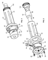
- a tool formed of a cable stripper 20 and an associated cutting assembly 22 is used for stripping a cable (not shown).
- the cutting assembly 22 is used to cut the cable seated in the cable stripper 20.
- Differently sized cutting assemblies can be easily and quickly mounted to and disassembled from the cable stripper 20.
- the cable stripper 20 has first and second ends 24, 26 with a centerline 28 defined therebetween.
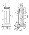
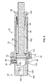
- the cable stripper 20 includes a handle 30, a one-way bearing 32, a plurality of pins 34 which are sandwiched between the handle 30 and the bearing 32, a washer 36 and a plurality of fasteners 38, such as conventional screws, for connecting the handle 30 and the bearing 32 together, a spring-loaded plunger 40 for connecting the cutting assembly 22 to the handle 30, and a depth stop assembly 42 mounted in the handle 30 for setting the amount of cable seated within the cable stripper 20 so that the cutting assembly 22 is positioned in the desired position.
- the pins 34 are conventional and are formed as cylinders.
- the handle 30 includes an elongated cylindrical body 44 having first and second ends, and a cylindrical collar 46 extending from the second end and outwardly from the body 44.
- the collar 46 has an outer diameter which is larger than the outer diameter of the body 44.
- the outer surface of the body 44 can have a plurality of spaced apart grooves 48 therein to allow for a user to easily grip the handle 30.
- the outer surface of the body 44 can be knurled.
- First, second and third inner walls define a central passageway 50 which extends through the body 44 and the collar 46.
- the central passageway 50 has a first portion 52 defined by the first inner wall and which extends through the body 44, and a second portion 54 defined by the second and third inner walls and which extends through the collar 46.
- the second portion 54 has a larger diameter than the diameter of the first portion 52 such that a shoulder 56 is defined by the second inner wall.
- a through-hole 57 is provided through the body 44 and is in communication with the central passageway 50.
- the through-hole 44 is proximate to, but spaced from, the first end of the body 44.
- a plurality of spaced apart blind bores 58 are provided in the second end of the collar 44.
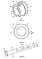
- the one-way bearing 32 includes an elongated cylindrical body 60 having first and second ends, and a cylindrical collar 62 extending from the first end of the body 60 and outwardly therefrom.
- the collar 62 has an outer diameter which is larger than the outer diameter of the body 60.
- First, second and third inner walls define a central passageway 64 which extends through the body 60 and the collar 62.
- the first inner wall defines a first portion 66 of the central passageway 64 which extends through the collar 62
- the second inner wall defines a second portion 68 of the central passageway 64 which extends through the body 60.
- the first portion 66 has a smaller diameter than the diameter of the second portion 68 such that a shoulder 70 is defined in the central passageway 64 by the second inner wall.
- a through-hole 72 is provided through the body 60 and is in communication with the central passageway 64. The through-hole 72 is proximate to, but spaced from, the second end of the body 60.
- the collar 62 of the one-way bearing 32 has a plurality of equi-distantly spaced apart pockets 74 formed therein which extend from the first end of the collar 62 to the second end of the collar 62.
- the pockets 74 may be formed by machining.
- Each pocket 74 is defined by a first end wall 76 and a second end wall 78 which is spaced from the first end wall 76 by a base wall 80.
- the first end wall 76 extends radially outwardly from the center of the collar 62, and the second end wall 78 is parallel to the first end wall 76.
- each pocket 74 angles from the first end wall 76 to the second end wall 78; the end of the base wall 80 commencing at the first end wall 76 is spaced radially inwardly from the end of the base wall 80 commencing at the second end wall 78.
- a pin 34 is placed into each pocket 74 such that the pin 34 can roll along the base wall 80 of the respective pocket 74 and between the end walls 76, 78.
- the collar 62 of the bearing 32 seats in the second portion 54 of the central passageway 50 of the handle 30 such that the first end of the collar 62 abuts against the shoulder 56.
- the second portion 54 of the central passageway 50 of the handle 30 has a diameter which is just slightly larger than outer diameter of the collar 62 of the bearing 32. The first end of each pin 34 abuts against the shoulder 56 which prevents the pins 34 from falling out of the first end of the pockets 74.
- the washer 36 is formed of a circular body 82 having a central passageway 84.
- a plurality of spaced apart through-holes 86 are provided through the body 82.
- the washer 36 seats around the body 60 of the bearing 32 and abuts against the second end of the collar 62 of the bearing 32 and the second end of the collar 46 of the handle 30.
- the through-holes 86 in the washer 36 align with the blind bores 58 in the collar 46 of the handle 30 and the fasteners 38 are seated therein to mate the bearing 32 and the handle 30 together.
- the second ends of the pins 34 abut against the washer 36 to prevent the pins 34 from falling out of the second end of the pockets 74.
- the central passageways 50, 64 align with each other to form a continuous passageway through the cable stripper 20.
- the spring-loaded plunger 40 is attached to the bearing 32 and is used to mount the cutting assembly 22 to the cable stripper 20 as described herein.
- the spring-loaded plunger 40 is conventional and generally includes a shaft 88 around which a spring 90 is seated, a head 92 on the end of the shaft 88 and a housing 94 into which the shaft 88 and spring 90 are mounted.
- the spring 90 is trapped on the shaft 88 by the head 92 and the housing 94.
- the shaft 88 extends through a passageway in the housing 94.
- the spring-loaded plunger 40 is mounted on the body 60 of the bearing 32 with the shaft 88 extending through the through-hole 72 and into the second portion 68 of the central passageway 64.
- the depth stop assembly 42 is mounted in the handle 30 and includes a rod 96, a sleeve 98 and a locking clamp 100.
- the depth stop assembly 42 is hand-tightenable to set a depth stop for the cable stripping length requirements. This eliminates the need for secondary tools to set the depth.
- the rod 96 is formed of an elongate shaft 102 with an enlarged head 104 at an end thereof.
- the head 104 has an outer diameter which is larger than the outer diameter of the shaft 102.
- the head 104 and a portion of the shaft 102 seats in the first portion 52 of the central passageway 50 through the handle 30 and the shaft 102 extends outwardly from the first end of the handle 30.
- the rod 96 can be slid within the central passageway 50 to move the head 104 to different positions within the handle 30.
- a plurality of markings 106 are provided on the shaft 102 to allow a user to visually determine the position of the head 104 within the central passageway 50.
- the shaft 102 is cylindrical to mate with the cylindrical profile of the central passageway 50. It is to be understood that other (e.g., non-cylindrical) profiles can be used for the shaft 102 and central passageway 50, provided the two components can be slid relative to each other and that the shape of a cable is accommodated in the central passageway 50.
- the sleeve 98 is formed of a body 108 having an end wall 110 at one end thereof.
- First, second and third inner walls 112, 114, 116 define a central passageway 118 which extends through the body 108 and the end wall 110.
- the first inner wall 112 has threads along a section thereof which extends from the first end of the body.
- the first inner wall 112 defines a first portion of the central passageway 118 which extends from the first end of the body 108
- the second inner wall 114 defines a second portion of the central passageway 118 and extends from the end of the first portion
- the third inner wall 116 defines a third portion of the central passageway and extends from the opposite end of the second portion.
- the first inner wall 112 has a diameter which is larger a diameter defined by the third inner wall 116.
- the second inner wall 114 tapers inwardly from the first inner wall 112 to the third inner wall 116.
- a through-hole 122 is provided through the body 108 proximate to the second end thereof.
- the locking clamp 100 has a head 124, a body 126 extending from the head 124 and a plurality of spaced apart fingers 128 extending from the body 126.
- a constant diameter central passageway 130 extends through the locking clamp 100 from the first end to the second end.
- the head 124 has an outer diameter which is greater than the outer diameter of the body 126.
- the head 124 has a plurality of ridges 132 provided thereon to allow a user to easily grip the locking clamp 100.
- the body 126 has threads 133 on its exterior surface.
- Each finger 128 is arcuate in plan view and has a constant thickness body portion 134 with an end portion 136 that tapers inwardly.
- the angle of the taper of the end portion 36 generally conforms with the angle of the taper of the second inner wall 114 in the sleeve 98.
- the rod 96 is seated through the sleeve 98 such that the head 104 of the rod 96 is proximate to the end portions 136 of the fingers 128.
- the combined rod 96 and sleeve 98 are seated within the first portion 52 of the central passageway 50 of the handle 30 such that the first end of the sleeve 98 aligns with the first end of the handle 30 and the rod shaft 102 extends at least partially outwardly from the first end of the handle 30.
- the through-hole 57 through the body 44 of the handle 30 and the through-hole 122 through the body 108 of the sleeve 98 are aligned with each other and a locking pin 138 is seated therein to mate the handle 30 and the sleeve 98 together and to prevent relative movement between the handle 30 and the sleeve 98.
- the locking clamp 100 is slid over the first end of the shaft 102 and along the shaft 102 until the fingers 128 seat between the shaft 102 and the handle 30.
- the threads 133 on the locking clamp 100 are engaged with the threads 120 on the sleeve 98.
- the fingers 128 are moved toward the second wall 114 of the sleeve 98 and engage with the second wall 114.
- the angles on the fingers 128 and on the second wall 114 causes the fingers 128 to move radially inwardly to grip the shaft 102 of the rod 96.
- the threading action of the locking clamp 100 allows the user to exhibit force in a linear fashion through twisting the locking clamp 100, which in turn presses the fingers 128 to lock on to the rod shaft 102 to provide a positive stop to a cable strip length.
- the rod 96 can be easily repositioned by unscrewing the locking clamp 100 until the fingers 128 expand radially outwardly and the rod 96 is released for movement. Once the rod 96 is moved to the next desired position, the locking clamp 100 is re-engaged to lock the position of the rod 96 relative to the handle 30.
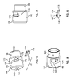
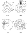
- the cutting assembly 22 is mounted to the cable stripper 20 and is used to cut the cable seated in the cable stripper 20. As best shown in FIGS. 16-21 , the cutting assembly 22 includes a bushing 140 and a blade 142 attached thereto by a fastener 144.
- the bushing 140 is of a predetermined size, which is dependent on the size of the cable to be seated therein.
- the bushing 140 is formed of a body 146 having an end wall 148 at a second end thereof, and a collar 150 extending from a first end of the body 146.
- the body 146 has an outer diameter which is larger than the outer diameter of the collar 150.
- First, second, third, fourth and fifth inner walls 152, 154, 156, 158, 160 define a central passageway 162 which extends through the collar 150, the body 146 and the end wall 148.
- a centerline 164 extends along the center of the central passageway 162.
- the first, second and third inner walls 152, 154, 156 defines a first portion of the central passageway 162 which extends through the collar 150
- the fourth and fifth inner walls 158, 160 defines a second portion of the central passageway 162 which extends through the body 146.
- the first inner wall 152 tapers inwardly from the first end of the collar 150.
- the second inner wall 154 extends rearwardly from the second end of the first inner wall 152 and is parallel to the centerline 164.
- the third inner wall 156 tapers outwardly from the second inner wall 154.
- the fourth inner wall 158 extends rearwardly from the second end of the third inner wall 156 and is parallel to the centerline 164.
- the fifth inner wall 160 tapers outwardly from the fourth inner wall 158.
- the first inner wall 154 defines a diameter which is larger than the diameter defined by the fourth inner wall 158.
- a through-hole 166 is provided through the collar 160 proximate to the first end thereof and are in communication with the first portion of the central passageway 162.
- a through-passageway 168 is provided through the body 146 and is in communication with the second portion of the central passageway 162.
- the through-passageway 168 is defined by a wall 170.
- the centerline of the through-passageway 168 is perpendicular to the centerline 164.
- a recess 172 is provided in the body 146 and is proximate to the through-passageway 168.
- the recess 172 provides a seat surface 174 onto which the blade 142 is mounted.
- the seat surface 174 is parallel to a plane defined by the centerline 164.
- the blade 142 has a body portion 176 with a cutting edge 178 at an end thereof.
- An elongated aperture 180 is provided through the body portion 176.
- the blade 142 mounts on the seat surface 174 such that the cutting edge 178 is angled relative to the centerline 164 of the bushing 140.
- the cutting edge 178 extends into the through-passageway 168 and into the second portion of the central passageway 162 as best shown in FIGS. 24 and 25 .
- a fastener 144 secures the body portion 176 to the bushing 140 through the elongated aperture 180.
- the body portion 176 can be slid along the seat surface 174 to change the position of the cutting edge 178 relative to the cable mounted in the cutting assembly 22; the size of the elongated aperture 180 limits the amount of travel of the body portion 176.
- the fastener 144 is retightened to secure the body portion 176 in the desired position.
- the cutting assembly 22 is attached to the cable stripper 20 by inserting the collar 150 of the cutting assembly 22 into the body 60 of the bearing 32 until the first end of the cutting assembly 22 engages the shoulder 70.
- the shaft 88 of the spring-loaded plunger 40 engages through the through-hole 166 in the bushing 140 to mate the bushing 140 and the bearing 32 together.
- the central passageways 50, 64, 118, 162 align.
- the shaft 88 of the spring-loaded plunger 40 also bears against the cable.
- the cutting assembly 22 is easily released from the cable stripper 20 by retracting the shaft 88 of the spring-loaded plunger 40 out of the through-hole 166 and pulling the cutting assembly 22 outwardly from the cable stripper 20.
- Differently sized cutting assemblies can be easily and quickly mounted to and disassembled from the remainder of the cable stripper 20.
- the cable to be cut/stripped is inserted into the second end of the cutting assembly 22, through the cutting assembly 22, through the one-way bearing 32 and into the handle 30 until the end of the cable abuts the head 104 of the rod 96.
- the cable is then secured in the cable stripper 20 by its engagement with the spring-loaded plunger 40.
- the blade 142 engages with the cable to hold the cable in the cable stripper 20.
- a ratcheting-type action is used.
- the handle 30 is rotated relative to the bearing 32.
- the pockets 74 in the bearing 32 provide space for the pins 34 to roll freely.
- the friction of the pins 34 between the bearing 32 and the handle 30 allow torque to be transferred from the handle 30 to the bearing 32, which provides a torque transmission to the bushing 140. Since a one-way bearing 32 is provided, the user can only use the cable stripper 20 in the intended direction.
Landscapes
- Engineering & Computer Science (AREA)
- General Engineering & Computer Science (AREA)
- Mechanical Engineering (AREA)
- Removal Of Insulation Or Armoring From Wires Or Cables (AREA)
- Manufacturing & Machinery (AREA)
- Knives (AREA)
Applications Claiming Priority (1)
| Application Number | Priority Date | Filing Date | Title |
|---|---|---|---|
| US201361884341P | 2013-09-30 | 2013-09-30 |
Publications (2)
| Publication Number | Publication Date |
|---|---|
| EP2854245A2 true EP2854245A2 (de) | 2015-04-01 |
| EP2854245A3 EP2854245A3 (de) | 2015-07-01 |
Family
ID=51625906
Family Applications (1)
| Application Number | Title | Priority Date | Filing Date |
|---|---|---|---|
| EP14186736.6A Withdrawn EP2854245A3 (de) | 2013-09-30 | 2014-09-29 | Kabelabisolierer und Schneidanordnung zum Abziehen eines Kabels |
Country Status (3)
| Country | Link |
|---|---|
| US (1) | US9391435B2 (de) |
| EP (1) | EP2854245A3 (de) |
| CN (1) | CN104518393A (de) |
Cited By (3)
| Publication number | Priority date | Publication date | Assignee | Title |
|---|---|---|---|---|
| ITUA20162065A1 (it) * | 2016-03-08 | 2017-09-08 | Intercable Srl | Spellacavi per cavi a diametro specifico |
| US20200076172A1 (en) * | 2018-08-30 | 2020-03-05 | Milwaukee Electric Tool Corporation | Wire stripper |
| JP2021083247A (ja) * | 2019-11-21 | 2021-05-27 | 日本リーテック株式会社 | 皮剥器の基端部構造、および、皮剥器 |
Families Citing this family (21)
| Publication number | Priority date | Publication date | Assignee | Title |
|---|---|---|---|---|
| FR2992110B3 (fr) * | 2012-06-14 | 2014-12-12 | Stanley Works Europe Gmbh | Outil de denudage de cables electriques |
| US9461448B1 (en) * | 2013-01-16 | 2016-10-04 | O'Brien Holding Co., Inc. | Tool for removing jacket material from tubing and cable |
| CN105703282A (zh) * | 2016-04-08 | 2016-06-22 | 黄永怀 | 一种电源线自动剥皮机压合铸件 |
| CN106877119B (zh) * | 2016-12-30 | 2020-09-11 | 赣州朝歌科技有限公司 | 一种自动剥线机 |
| CN106549343A (zh) * | 2017-02-07 | 2017-03-29 | 浙江容大电力工程有限公司输变电分公司 | 一种用于架空绝缘导线的剥皮器 |
| RS66795B1 (sr) * | 2017-06-30 | 2025-06-30 | Komax Holding Ag | Postupak poravnavanja za uređaj za obradu kablova |
| CN107681417A (zh) * | 2017-10-09 | 2018-02-09 | 浙江欧导自动化设备有限公司 | 一种漆包线表面剥皮用枪头 |
| CN108493847B (zh) * | 2018-03-22 | 2020-12-18 | 国网福建省电力有限公司厦门供电公司 | 一种套筒式绝缘导线快速剥线器 |
| US10875201B2 (en) | 2018-04-04 | 2020-12-29 | Swanstrom Tools Usa Inc. | Relief guard for hand tools |
| US11276993B2 (en) | 2018-06-20 | 2022-03-15 | Anthony Sedlacek | Cable-jacket removal tool |
| BR112021012015A2 (pt) | 2018-12-21 | 2021-09-08 | 3M Innovative Properties Company | Dispositivo de preparo de cabo de força elétrico |
| US12126151B2 (en) | 2018-12-21 | 2024-10-22 | 3M Innovative Properties Company | Electrical power cable preparation system |
| CN109904712A (zh) * | 2019-02-28 | 2019-06-18 | 国家电网有限公司 | 一种供电公司用多功能接线工具 |
| EP4082085A1 (de) | 2019-12-26 | 2022-11-02 | 3M Innovative Properties Company | Greiferwerkzeug für kabelvorbereitungssystem |
| CN115151829A (zh) | 2019-12-31 | 2022-10-04 | 3M创新有限公司 | 本地局部放电监测 |
| CN111697412A (zh) * | 2020-06-01 | 2020-09-22 | 深圳供电局有限公司 | 开剥装置 |
| KR102798761B1 (ko) * | 2022-04-22 | 2025-04-25 | 고한주 | 간접활선 전선용 피박기 |
| WO2025189129A2 (en) | 2024-03-08 | 2025-09-12 | Black & Decker Inc. | Power tool accessory for removing protective covers from cables |
| USD1046587S1 (en) * | 2024-06-20 | 2024-10-15 | Jiangyong Huang | Wire stripper |
| USD1110828S1 (en) * | 2025-01-14 | 2026-02-03 | Wenzhou Zhongtian Precision Technology Co., Ltd. | Electric wire stripper |
| CN120511598B (zh) * | 2025-05-21 | 2025-12-12 | 江苏凡尔科技有限公司 | 高压电缆绝缘外半导体层剥离装置 |
Family Cites Families (36)
| Publication number | Priority date | Publication date | Assignee | Title |
|---|---|---|---|---|
| US2437514A (en) * | 1946-01-23 | 1948-03-09 | Glenn G Givens | Tool for cutting insulation on electric conductors |
| US2624221A (en) * | 1948-01-09 | 1953-01-06 | Western Electric Co | Sheath stripper for cable having twisted conductors |
| US3398610A (en) * | 1967-05-15 | 1968-08-27 | James J. Matthews | Insulation end removing tool |
| US3433106A (en) * | 1967-07-13 | 1969-03-18 | James J Matthews | Apparatus for removing insulation |
| US3377891A (en) * | 1967-07-17 | 1968-04-16 | Scott & Fetzer Co | Cable insulation removing tool |
| US3533313A (en) * | 1968-02-02 | 1970-10-13 | James J Matthews | Tool for stripping insulation |
| US3566466A (en) * | 1969-04-17 | 1971-03-02 | James J Matthews | Cable reducing tool |
| DE3214479C2 (de) * | 1981-07-22 | 1986-05-15 | Siemens AG, 1000 Berlin und 8000 München | Handgerät zum Abschälen der äußeren Mantelschicht elektrischer Leitungen und elektrischer Kabel |
| US4769910A (en) * | 1987-03-30 | 1988-09-13 | Northern Telecom Limited | Cutting tool for cylindrical articles |
| US4858315A (en) * | 1988-05-09 | 1989-08-22 | N. J. Wheeler | Shield stripping apparatus for electrical cable |
| US5511305A (en) * | 1994-06-06 | 1996-04-30 | Commscope | Core finish tool for coaxial cable and associated method |
| US5673486A (en) * | 1995-12-15 | 1997-10-07 | The Remarcable Co., Inc. | Method and apparatus for stripping a wire end |
| US5956852A (en) * | 1997-05-12 | 1999-09-28 | Capewell Components Company | Cable stripping tool for removing insulation from ribbed cable |
| JPH11344052A (ja) | 1998-04-02 | 1999-12-14 | Koyo Seiko Co Ltd | 一方向クラッチ |
| US6381850B1 (en) * | 1999-03-09 | 2002-05-07 | Ted Warner | Wire stripping and preparation apparatus |
| US6622386B2 (en) * | 2000-03-20 | 2003-09-23 | Lemco Tool Corporation | Cable stripping tool |
| DE50107253D1 (de) * | 2000-06-05 | 2005-10-06 | Pf Schweistechnologie Gmbh | Schälgerät |
| US6530152B1 (en) * | 2000-10-20 | 2003-03-11 | John Mezzalingua Associates, Inc. | Tool for stripping coaxial cable |
| US6467171B2 (en) * | 2001-03-09 | 2002-10-22 | Capewell Components Company, Llc | Compound coaxial cable stripping tool |
| US6581291B1 (en) | 2001-10-09 | 2003-06-24 | Capewell Components Company, Llc | Cable stripping tool |
| US6618945B2 (en) * | 2001-12-19 | 2003-09-16 | Holland Electronics, Llc | Microcable stripping tool |
| US7160351B2 (en) | 2002-10-01 | 2007-01-09 | Pmg Ohio Corp. | Powder metal clutch races for one-way clutches and method of manufacture |
| DE10312507B4 (de) * | 2003-03-15 | 2007-07-26 | Laux Industrie Gmbh | Handschneidgerät zum Ablängen von Kabeln |
| US20040221456A1 (en) * | 2003-05-06 | 2004-11-11 | Losinger Roger M. | [cable stripping and boring tool] |
| US6668458B1 (en) * | 2003-06-04 | 2003-12-30 | Paul Schoenleber | Automatic field cable stripper |
| US20050066528A1 (en) * | 2003-09-25 | 2005-03-31 | Ducret Lucien C. | Cable armor stripper |
| DK1690324T3 (da) * | 2003-11-25 | 2008-04-28 | Commscope Inc | Kerneboreværktöj til koaksialkabel |
| US7171753B2 (en) * | 2004-06-15 | 2007-02-06 | Andrew Corporation | Multi-cable jacket removal tool |
| FR2901643B1 (fr) * | 2006-05-29 | 2011-05-06 | Derancourt | Outil a main pour le denudage des cables electriques |
| US7694420B2 (en) * | 2007-07-19 | 2010-04-13 | John Mezzalingua Associates, Inc. | Coaxial cable preparation tool and method of use thereof |
| US7984553B1 (en) * | 2007-08-31 | 2011-07-26 | Miller Michael R | Cable preparation tool |
| US8578820B2 (en) * | 2009-04-28 | 2013-11-12 | Reinhold Franz Wirth | Electrical wire tool |
| US20110010945A1 (en) * | 2009-07-16 | 2011-01-20 | Daryle Delafosse | Cable slitter |
| US9748748B2 (en) * | 2011-08-16 | 2017-08-29 | Southwire Company, Llc | Cable stripper |
| US20130055571A1 (en) * | 2011-09-01 | 2013-03-07 | John Mezzalingua Associates, Inc. | Adjustable preparation tool and method of use thereof |
| WO2013119745A1 (en) * | 2012-02-10 | 2013-08-15 | Corning Cable Systems Llc | A method for stripping long segments of buffered optical fiber and a tool for performing the same |
-
2014
- 2014-09-29 EP EP14186736.6A patent/EP2854245A3/de not_active Withdrawn
- 2014-09-30 CN CN201410698826.XA patent/CN104518393A/zh active Pending
- 2014-09-30 US US14/501,204 patent/US9391435B2/en active Active
Non-Patent Citations (1)
| Title |
|---|
| None |
Cited By (6)
| Publication number | Priority date | Publication date | Assignee | Title |
|---|---|---|---|---|
| ITUA20162065A1 (it) * | 2016-03-08 | 2017-09-08 | Intercable Srl | Spellacavi per cavi a diametro specifico |
| US20200076172A1 (en) * | 2018-08-30 | 2020-03-05 | Milwaukee Electric Tool Corporation | Wire stripper |
| US11689003B2 (en) * | 2018-08-30 | 2023-06-27 | Milwaukee Electric Tool Corporation | Wire stripper |
| US12040599B2 (en) | 2018-08-30 | 2024-07-16 | Milwaukee Electric Tool Corporation | Wire stripper |
| JP2021083247A (ja) * | 2019-11-21 | 2021-05-27 | 日本リーテック株式会社 | 皮剥器の基端部構造、および、皮剥器 |
| WO2021100370A1 (ja) * | 2019-11-21 | 2021-05-27 | 株式会社永木精機 | 皮剥器の基端部構造、および、皮剥器 |
Also Published As
| Publication number | Publication date |
|---|---|
| US9391435B2 (en) | 2016-07-12 |
| CN104518393A (zh) | 2015-04-15 |
| EP2854245A3 (de) | 2015-07-01 |
| US20150089815A1 (en) | 2015-04-02 |
Similar Documents
| Publication | Publication Date | Title |
|---|---|---|
| US9391435B2 (en) | Cable stripper and cutting assembly for stripping a cable | |
| US9027908B1 (en) | Field-installable pulling eye | |
| US10574040B2 (en) | Cable stripper having an adjustable bushing | |
| US9929548B2 (en) | Cable stripper having an adjustable bushing | |
| EP2450147B1 (de) | Schnellfreigabe-Bit-Adapter | |
| EP2845673B1 (de) | Spanndornanordnung und Verfahren zur Montage | |
| US20140215830A1 (en) | Tool for slitting jacket of eletrical cable | |
| US20030188432A1 (en) | Cable and wire stripper | |
| US20160036206A1 (en) | Handheld Wire Stripper Tool Device | |
| US9698580B2 (en) | Screwdriver having cable-stripping structure | |
| EP2992172B1 (de) | Fischwerkzeug mit faserverbundstange | |
| US9472927B2 (en) | Wire stripping and cutting tool | |
| WO2014118169A9 (de) | Abknickbare haltevorrichtung | |
| TWI499149B (zh) | 電纜線剝皮工具 | |
| JP6006917B2 (ja) | ケーブルの被覆剥ぎ取り工具 | |
| US20070001157A1 (en) | Conduit leader | |
| US5161301A (en) | Double-barrelled contact tool and method of using same | |
| CA2919284C (en) | Electrical connectors and related methods | |
| EP2854244A2 (de) | Abisolierzange | |
| US20170054280A1 (en) | Cable stripping tool and bi-directional cutting blade | |
| US20140076109A1 (en) | Integrated rotary cable stripper | |
| US11484995B2 (en) | Conduit connector tool | |
| WO2017176198A1 (en) | Wire stripper with adjustable positioning guide | |
| JP2018029445A (ja) | ケーブル被覆剥離工具 | |
| KR100947894B1 (ko) | 동축케이블용 스트리퍼 |
Legal Events
| Date | Code | Title | Description |
|---|---|---|---|
| PUAI | Public reference made under article 153(3) epc to a published international application that has entered the european phase |
Free format text: ORIGINAL CODE: 0009012 |
|
| 17P | Request for examination filed |
Effective date: 20140929 |
|
| AK | Designated contracting states |
Kind code of ref document: A2 Designated state(s): AL AT BE BG CH CY CZ DE DK EE ES FI FR GB GR HR HU IE IS IT LI LT LU LV MC MK MT NL NO PL PT RO RS SE SI SK SM TR |
|
| AX | Request for extension of the european patent |
Extension state: BA ME |
|
| PUAL | Search report despatched |
Free format text: ORIGINAL CODE: 0009013 |
|
| AK | Designated contracting states |
Kind code of ref document: A3 Designated state(s): AL AT BE BG CH CY CZ DE DK EE ES FI FR GB GR HR HU IE IS IT LI LT LU LV MC MK MT NL NO PL PT RO RS SE SI SK SM TR |
|
| AX | Request for extension of the european patent |
Extension state: BA ME |
|
| RIC1 | Information provided on ipc code assigned before grant |
Ipc: H02G 1/12 20060101AFI20150528BHEP |
|
| R17P | Request for examination filed (corrected) |
Effective date: 20151229 |
|
| RBV | Designated contracting states (corrected) |
Designated state(s): AL AT BE BG CH CY CZ DE DK EE ES FI FR GB GR HR HU IE IS IT LI LT LU LV MC MK MT NL NO PL PT RO RS SE SI SK SM TR |
|
| RAP1 | Party data changed (applicant data changed or rights of an application transferred) |
Owner name: TEXTRON INNOVATIONS INC. |
|
| 17Q | First examination report despatched |
Effective date: 20170404 |
|
| STAA | Information on the status of an ep patent application or granted ep patent |
Free format text: STATUS: THE APPLICATION IS DEEMED TO BE WITHDRAWN |
|
| 18D | Application deemed to be withdrawn |
Effective date: 20170815 |