EP2854482A1 - Procédé de génération d'une séquence de mots de code binaires d'un code à bits multiples pour un signal de commande Pulse Modulated pour un consommateur - Google Patents
Procédé de génération d'une séquence de mots de code binaires d'un code à bits multiples pour un signal de commande Pulse Modulated pour un consommateur Download PDFInfo
- Publication number
- EP2854482A1 EP2854482A1 EP14155995.5A EP14155995A EP2854482A1 EP 2854482 A1 EP2854482 A1 EP 2854482A1 EP 14155995 A EP14155995 A EP 14155995A EP 2854482 A1 EP2854482 A1 EP 2854482A1
- Authority
- EP
- European Patent Office
- Prior art keywords
- code
- pcm
- der
- die
- oder
- Prior art date
- Legal status (The legal status is an assumption and is not a legal conclusion. Google has not performed a legal analysis and makes no representation as to the accuracy of the status listed.)
- Withdrawn
Links
- 238000000034 method Methods 0.000 title claims abstract description 47
- 238000001228 spectrum Methods 0.000 claims description 31
- 230000015572 biosynthetic process Effects 0.000 claims description 4
- 230000001939 inductive effect Effects 0.000 claims description 4
- 230000003071 parasitic effect Effects 0.000 claims description 4
- 230000002123 temporal effect Effects 0.000 claims description 3
- 101000906927 Homo sapiens N-chimaerin Proteins 0.000 description 17
- 102100023648 N-chimaerin Human genes 0.000 description 17
- 208000035195 congenital hypomyelinating 3 neuropathy Diseases 0.000 description 13
- 208000035196 congenital hypomyelinating 2 neuropathy Diseases 0.000 description 11
- 230000001276 controlling effect Effects 0.000 description 9
- 238000011156 evaluation Methods 0.000 description 9
- 230000005540 biological transmission Effects 0.000 description 6
- 239000003086 colorant Substances 0.000 description 6
- 230000006870 function Effects 0.000 description 6
- 238000005286 illumination Methods 0.000 description 6
- 230000008901 benefit Effects 0.000 description 5
- 230000035945 sensitivity Effects 0.000 description 5
- 241001136792 Alle Species 0.000 description 4
- 241000220225 Malus Species 0.000 description 4
- 230000007935 neutral effect Effects 0.000 description 3
- 240000003517 Elaeocarpus dentatus Species 0.000 description 2
- 241000726409 Satellites Species 0.000 description 2
- 230000004913 activation Effects 0.000 description 2
- 238000005311 autocorrelation function Methods 0.000 description 2
- 230000006399 behavior Effects 0.000 description 2
- 230000008859 change Effects 0.000 description 2
- 238000010276 construction Methods 0.000 description 2
- 238000005314 correlation function Methods 0.000 description 2
- 238000013461 design Methods 0.000 description 2
- 230000000694 effects Effects 0.000 description 2
- 230000004044 response Effects 0.000 description 2
- 210000002023 somite Anatomy 0.000 description 2
- 238000001279 elastic incoherent neutron scattering Methods 0.000 description 1
- 238000000295 emission spectrum Methods 0.000 description 1
- 238000005516 engineering process Methods 0.000 description 1
- 230000005284 excitation Effects 0.000 description 1
- 230000007717 exclusion Effects 0.000 description 1
- 230000005669 field effect Effects 0.000 description 1
- 238000004519 manufacturing process Methods 0.000 description 1
- 238000013507 mapping Methods 0.000 description 1
- 230000004048 modification Effects 0.000 description 1
- 238000012986 modification Methods 0.000 description 1
- 230000010355 oscillation Effects 0.000 description 1
- 230000000737 periodic effect Effects 0.000 description 1
- 230000005855 radiation Effects 0.000 description 1
- 230000009467 reduction Effects 0.000 description 1
- 230000001105 regulatory effect Effects 0.000 description 1
- 230000011664 signaling Effects 0.000 description 1
- 230000003595 spectral effect Effects 0.000 description 1
- 238000010971 suitability test Methods 0.000 description 1
- 230000036962 time dependent Effects 0.000 description 1
- 230000009466 transformation Effects 0.000 description 1
Images



Classifications
-
- H—ELECTRICITY
- H05—ELECTRIC TECHNIQUES NOT OTHERWISE PROVIDED FOR
- H05B—ELECTRIC HEATING; ELECTRIC LIGHT SOURCES NOT OTHERWISE PROVIDED FOR; CIRCUIT ARRANGEMENTS FOR ELECTRIC LIGHT SOURCES, IN GENERAL
- H05B45/00—Circuit arrangements for operating light-emitting diodes [LED]
- H05B45/30—Driver circuits
- H05B45/345—Current stabilisation; Maintaining constant current
-
- H—ELECTRICITY
- H05—ELECTRIC TECHNIQUES NOT OTHERWISE PROVIDED FOR
- H05B—ELECTRIC HEATING; ELECTRIC LIGHT SOURCES NOT OTHERWISE PROVIDED FOR; CIRCUIT ARRANGEMENTS FOR ELECTRIC LIGHT SOURCES, IN GENERAL
- H05B45/00—Circuit arrangements for operating light-emitting diodes [LED]
- H05B45/30—Driver circuits
- H05B45/32—Pulse-control circuits
Definitions
- the invention relates to a method for generating a sequence of binary codewords of a multi-bit code for a Pulse Code Modulated (PCM) drive signal for a consumer, in particular in its use in a lighting device and in particular in a device for setting multi-colored light scenes in a motor vehicle.
- PCM Pulse Code Modulated
- Electric / electronic consumers can z. B. are controlled quite accurately by pulse modulation.
- the invention in which a PCM modulation is used, is described on the basis of the driving of LEDs as an example of an electronic consumer.
- the PWM modulation has some disadvantages, in particular with regard to EMC aspects, which will be described in detail below.
- Pulse width modulation respectively pulse length modulation (see also " Karsten Block, Peter Busch, Ludger Erwig, Franz Fischer, Wilken Pape, Manfredmgerber: Electrical professions. Learning fields 9-13. Energy and building technology. 1st edition. Academicsverlag EINS, Troisdorf 2006. ISBN 978-3-427-44464-0. P.
- PLM for pulse-length modulation is a type of modulation in which a technical variable (eg the electric current) alternates between two values, whereby the duty cycle of a rectangular pulse is modulated at constant frequency Width of the pulses forming it
- the English term for the method is Pulse Width Modulation (PWM)
- PWM Pulse Width Modulation
- PDM Pulse Width Modulation
- lighting devices are known in the art that include a plurality of light emitters in at least two different colors that are configured to be coupled to a circuit having a current source and a common potential reference and driver (TR1, TR2, TR3, DRV ) for operating the plurality of light emitters, of which at least two are connected to the plurality of light emitters and the circuit and comprise the respective current paths of the at least two differently colored light emitters corresponding switches.
- said prior art lighting device includes control for periodically and independently opening and closing at least two switches.
- the controller has a variable bus address assigned to it from outside in order to identify and respond to the address portion of an input data flow, the data flow portion, in particular an addressed data packet, being assigned to this controller.
- this lighting device of the prior art is characterized in particular in that each light emitter is an LED and the controller generates a plurality of PWM signals, each PWM signal each one of the PWM signals causes a corresponding one of the at least two opening and closing switches with corresponding frequencies according to the respective working cycles and wherein the data flow component data for determining the respective working cycles of the at least two differently colored LEDs includes (see eg EP-B-1 016 062 ).
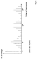
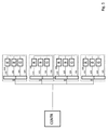
- Fig. 1 shows an exemplary spectrum for a bipolar PWM according to the prior art.
- an illumination device in which the light sources are operated to generate light of desired intensity and color by means of pulse modulation of a randomly controlled pulse width, which in turn adjusts white noise as a spectrum.
- the invention solves the problem of providing a device for supplying light emitters and / or LEDs with electrical energy, wherein an interference spectrum with reduced amplitude and in contrast to the prior art within certain limits modelable interference spectrum arise.
- a subtask to be given later in the description is the provision of a pseudo-random signal with a fill factor that deviates from 50%.
- the consumers are driven by means of a drive signal which is PCM-coded.
- the codewords of a multi-bit PCM code can be divided into several code classes, sorted by the number of their one-bits. Each code class represents a specific energy / power used by a consumer. If a consumer is to be controlled with a predeterminable energy / power which is assigned to a code class comprising a plurality of code words, their codewords will change according to the invention, in particular stochastically, ie randomly or quasi-randomly controlled, or else used in a deterministically varying manner.
- This has the advantage that the (interference) spectrum to be observed with regard to the EMC can be selected in advance or limited, and thus differs quite clearly from white noise. This, in turn, makes it much easier to take the measures required to ensure EMC, which, moreover, are much easier to implement.
- PCM Pulse Code Modulated
- PCM Pulse Code Modulated
- the Pulse Code Modulated (PCM) drive signals only from such code classes, which comprise a plurality of codewords represent codewords, one with respect to the number n of the bits of the multi-bit code percentage of Have one-bits lying between a predetermined lower and a predetermined upper limit and / or within one or more predetermined ranges.
- a subset of codewords is selected from the number of codewords of a code class, and that the codewords of this subset are used to form the Pulse Code Modulated (PCM) drive signal.
- PCM Pulse Code Modulated
- each Pulse Code Modulated (PCM) drive signal representing a codeword has a partial spectrum in the frequency domain and thus corresponds to a partial spectrum of each codeword of each code class and that those codewords whose partial spectra lie within a predeterminable overall spectrum, potentially be used for the formation of the Pulse Code Modulated (PCM) drive signal.
- PCM Pulse Code Modulated
- the clock frequency of the PCM drive signals, with which the code words are transmitted monofrequent or bandwidth limited with a lower limit frequency not equal to zero and an upper limit frequency and thus variable.
- one or more codewords of one or at least one other code class can be transmitted within a temporal sequence of codewords of a code class.
- a modification i. H. "sprinkling" codewords of code classes other than those representing the electrical voltage, electrical current, or electrical power with which the consumer is to be currently supplied may be advantageous in terms of the above-mentioned property limitations of a consumer.
- the at least two PCM drive signals do not correlate and / or only after a predefinable number of clocks, z. B. only after 256, 512, 1024, 2048 or 4096 cycles for one or a few bars each other. This measure serves to suppress the formation and / or the effects of disturbances.
- an expedient embodiment of the invention may also be provided to control the consumer, where appropriate, in addition to the PCM control with respect to the size of the supplied electrical power specifically or to regulate.
- This will be explained below with reference to an LED as a consumer, in which the drive unit controls the color temperature of the LED based on a desired and an actual color temperature value by the maximum current and / or the maximum voltage and / or the maximum energy of the respective PCM drive signal is controlled , As a result, the supply of the consumer with electrical power, adapted to its potential “property losses" and thus these are compensated.
- the background of this measure is that a consumer can react differently when being driven by the PCM signals with code words from the same code class.
- the load operates according to the codeword and succession of the one-bits for a different amount of time with the operating voltage defined by a one-bit or the corresponding operating current. This can z. B. have influence on the color temperature of lamps and in particular LEDs.
- this effect is corrected by a variable value (represented by a one-bit of the code) for the voltage, current or power to be supplied to the load.
- a variable value represented by a one-bit of the code
- the above finding can also be used to exclude those code words of a code class for a drive whose one-bit pattern for the operation of a consumer are less advantageous than other one-bit patterns of this class of code.
- the inventive method is particularly suitable for supplying at least one electrical / electronic such.
- an electromechanical, electro-optical or electro-acoustic consumer in particular a light source such.
- a light source such.
- an LED or a consumer with a possibly parasitic, ohmic and / or inductive and / or capacitive load, as in electrical / electronic articles / components in the automotive sector and / or daily life for z.
- electrical energy As residential and / or industrial buildings, accessories, transport are encountered, with electrical energy.
- the invention solves the problem of uncontrolled EMC emissions through the use of random bit sequences or pseudo random bit sequences.
- Such random sequences and pseudorandom sequences have the property that approximately 50% of the bits are 1 and approximately 50% of the bits are 0.
- a true random sequence is white noise. If such a sequence were used directly for controlling the light sources, in particular LEDs, their luminous intensity would also rush in frequency ranges that are perceived by the human eye. This is not wanted. It is therefore important that the random sequence is band limited. In particular, it is important that the amplitude of the control signal below a lower limit frequency ⁇ u is ideally zero or negligible for the application.
- T clk is the clock period for the shift operation.
- the feedback is done by a simple primitive polynomial.
- T P is the lower limit frequency. It should be noted, however, that such a pseudo-random sequence always has a mean expected value of about 50% for a 1 and thus is not suitable for amplitude control.
- this expectation value is referred to as "fill factor”, since it determines how many 1 bits on average come from how many 0 bits of a PCM codeword.
- the invention solves this sub-task by means of at least two predefinable codes, which are sent at a constant clock rate.
- predefinable codes which are sent at a constant clock rate.
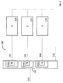
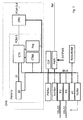
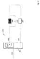
- a controlled device can have a plurality of lighting means (106, 107, 108, R, G, B) which are connected via supply lines (102, 103, 104) to a respective driver (TR1, TR2, TR3, DRV).
- a controller regulates the power and / or the current and / or the voltage which the respective driver (TR1, TR2, TR3, DRV) supplies to the lighting means (106, 107, 108, R, G, B).
- an LED circuit which may consist of parallel and series circuits of LEDs, this is preferably a current drive.
- a voltage or power control is equally useful.
- a PCM (CHN) channel In contrast to the prior art, in each of the drivers (TR1, TR2, Tr3, DRV), a PCM (CHN) channel generates a PCM (Pulse Code Modulation) signal (102, 103, 104) corresponding to a predetermined code, the active code, and the procedure described below.
- CHN PCM
- PCM Pulse Code Modulation
- This active code (in the said example, a 4-bit code) may each be stored in a memory (CTAB) for the exemplary 16 codes resulting from said exemplary 4 bits.
- CTAB memory
- CTAB code table
- the fill factor is the number of 1-bits in a code (in bits) divided by the length of the code (also expressed in bits) as a percentage. The maximum fill factor is therefore 100%.
- a numerical value of 0 of said exemplary 4-control bits is to correspond to a power output of 0% and a fill factor of 0%.
- a numerical value of 16, ie the numerical value of the code, with all 4 bits at logical 1, should correspond to a radiation power of 100% and a filling factor of 100%.
- a 3-bit data word corresponds to the selection of the fill factor, each with a code class.
- a code may have more than 16-bits for the said example, the concrete code being selected, for example, by a 4-bit random number from the set of codes with the same filling factor.
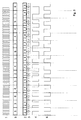
- code class 0 with fill factor 0% with only one code
- code class 1 with fill factor 25% with four codes
- code class 2 with fill factor 50% with six codes
- code class 3 with fill factor 75% with four codes
- code class 4 with fill factor 100% with again only one code (see the right column of the table).
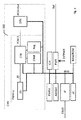
- the exchange can be done, for example, by generating a random or pseudorandom number (ZZ) in a random number generator (ZG), for example as described above, by means of a feedback shift register and a simple primitive polynomial implemented in the form of appropriate logic, for example; but not directly to control the lighting and / or the LED, but to select the active code to be used from the set of allowed and / or possible codes for the next transmission period from the codes of the given code class by a controller (CTR ) and defines this to be used active code.
- the code class corresponds to the desired fill factor. It corresponds in function to that of the duty cycle in a PWM. By selecting the code class, a filling factor for the PCM signal can be determined that deviates substantially from 50%.
- the entire PCM signal generated by the controller becomes a bandlimited aperiodic quasi-random or random signal with a fill factor corresponding to the selected code class appropriate for the driving of the lighting means and especially of LEDs.
- codes within a code class may be restricted due to EMC requirements. So it is conceivable, for example, based on the example discussed here, not to use all six codes with fill factor 50% (see table), but for example only two or even only one of these six possible codes. Using only one code, however, would result in a periodic signal, since then no selection of the code due to the random signal can take place and the PCM signal would lose the property of a random signal.
- a code bit sequence 0010 could thus be transformed to the sequence 0110 in which the first 1 of the sequence is not represented due to the low-pass characteristics of the driver (DRV, TR1, TR2, TR3), the leads (102, 103, 103) and the LEDs (106, 107, 108, R, G, B) so that the desired code 0010 again results as the active code effectively represented by the LEDs.
- a lighting device which can be controlled according to the invention therefore typically comprises a plurality of light means and / or LEDs in at least two, but typically three or four or more different colors, in a specific embodiment. These are typically designed to be connected to an electrical power supply.
- the power supply includes an electrical circuit and a common potential reference (105).
- the driver means (TR1, TR2, TR3, DRV) for operating the plurality of light emitters and / or LEDs are also part of the device.
- the driver means (TR1, TR2, TR3, DRV) are connected to the said light sources and / or LEDs and the circuit, and the respective current paths (102, 103, 104) comprise the switches and / or regulators corresponding to at least two differently colored light sources / LEDs , Furthermore, a control for the aperiodic and independent opening and closing of the at least two switches or at least two regulators is provided. In this case, under the opening and closing in the case of a said regulator, a reduction or increase in the energy throughput by the respective controller should be understood.
- the controller is connected to a wired or wireless data network and / or a data line and / or a data bus.
- the controller may have a variable from the outside by means of programming or with the aid of an address generator, which is part of the device variable bus address.
- This bus address is used by the device to z. B. from the data stream data, in particular data packets or other data messages, filter out. It thus identifies the respective proportion of an assigned input data flow and reacts thereto typically by changing a parameter of the device.
- CTAB code or parts of Code table
- CTAB whole code table
- the size of the code table (CTAB) does not necessarily have to be 2 n , where n denotes the length of the code. It is rather conceivable that the code table (CTAB) is implemented much shorter with fewer codes.
- the selection of the active codes is influenced by specifications via the said data interface.
- typically at least two of the luminous means are LEDs.
- the controller (101) typically generates a plurality of PCM signals (102, 103, 104) by means of the drivers (TR1, TR2, TR3).
- the PCM signals (102, 103, 104) do not correlate with each other. This non-correlation may also refer only to portions of the signals. For example, it is conceivable that a correlation only occurs after 256 or 512 or 1024 or 2048 or 4096 clocks, which does not correspond to the technical optimum. Non-corellation is not mandatory.
- Each of the PCM signals (102, 103, 104) corresponds in each case to one color of the plurality of LEDs (106, 107, 108, R, G, B) and / or light sources of different colors.
- each of the PCM signals (102, 103, 104) is generated by in each case at least one corresponding switch or controller associated with the respective PCM signal for opening and closing in accordance with the respective logic state of the internal PCM also associated with the respective PCM signal Signal (PCM-S) of the respective channel (CHN) of the control unit (101) is caused.
- the frequency spectrum of the magnitude of the frequency of the PCM signal is band limited as described above. This means that the signal has a lower limit frequency ⁇ u and / or an upper limit frequency ⁇ o .
- said data flow component determines the data for determining the respective active regions of the transmission codes which emit the at least two differently colored LEDs. It is particularly advantageous if the data flow component, that is to say typically a data packet intended for the device, determines a predefined or preprogrammed color palette in the form of a subset of the possible active codes.
- the device therefore has, per light source, a subdevice which converts the subset of the possible active codes corresponding to this data flow component into a random sequence of on and off signals and in particular into a PCM signal (PCM-S) for the said switch with the preselected fill factor.
- PCM-S PCM signal
- the controller comprises at least two registers for controlling the at least two differently colored lamps / LEDs.
- registers for controlling the at least two differently colored lamps / LEDs.
- parts of registers can be used instead of two registers.
- These registers or register parts are each used to store values which, for example, receives the said data interface from a data flow.
- These data flow components in particular data packets, are then assigned to the respective differently colored lamps / LEDs and, for example, each specify the said fill factor and thus the active code class. This can happen on the one hand in the form that the content of the data flow component directly reflects the fill factor that is to be used or, on the other hand, the contents of the data flow component directly or indirectly refer to the fill factor via further tables, which should be used.
- color palettes are conceivable, which can then refer to the register contents. This is particularly efficient when z. B. a restriction to 16 colors takes place. In this case, not all data, but for example, only a 4-bit data word for the color must be transmitted.
- the fill factor of each individual PCM signal (102, 103, 104, PCM-Out) is then determined using the color palette.
- the invention may conveniently have a controller adapted to adjust the code fill factor appropriately. It will be like described above, which type of code may be used at all.
- the possible filling factors of 0%, 25%, 50%, 75% and 100% of the exemplary code classes 0 to 4 result Filling factors close to the value of 50% each, the maximum number of code variations possible. If this code is sent to a light source or an LED, then the average duty cycle per duty cycle is equal to the product of code transmission time and fill factor. This means that the behavior is analogous to that of a PWM in which the data values for determining the average duty cycle per time unit are assigned to the associated color LEDs (general color lamps).
- the controller comprises at least one further register for the control of the at least two differently colored lamps or LEDs.
- this third register or this third register part is used in each case for storing a third value, which, for example, the said data interface also receives from a data flow.
- the direct use of the value is possible, but also the indirect use of a color palette possibly associated with the code palette.
- the content of the third value refers to the correct code table.
- This data flow component in particular a data packet, is allocated when the active code table is used directly and controls, for example, the selection of the codes from the code table.
- the device It is basically useful to provide the device with a housing which essentially surrounds the plurality of light sources or LEDs, the driver means (TR1, TR2, TR3, DRV) and the said controller (101).
- this includes an electrical regulator for controlling the supplied via the current paths to the plurality of LEDs Maximum currents so as to keep the maximum currents at constant maximum values.
- the amplitude of the PCM pulse signal is also typically controlled.
- the invention can provide a color sensor that allows the control unit (101) to adjust the fill factor and / or the color temperature of the lamps or LEDs so that the desired color emission or color reflection of the irradiated object is achieved.
- the latter comprises an electrical regulator for controlling the maximum energy supplied via the current paths to the plurality of light-emitting means or LEDs so as to keep the maximum energy absorbed by the light-emitting means or LEDs at constant maximum values.
- an electrical regulator for controlling the maximum energy supplied via the current paths to the plurality of light-emitting means or LEDs so as to keep the maximum energy absorbed by the light-emitting means or LEDs at constant maximum values.
- the latter comprises a regulator for controlling the maximum currents or the maximum electrical energy supplied via the current paths to the plurality of LEDs, in order thus to increase the maximum currents and / or maximum energy to constant maximum values
- the housing now essentially surrounds the controller (PWR) in addition to the plurality of LEDs, the driver means (TR1, TR2, TR3, DRV) and the controller (101).
- the controller for identifying and responding to an input data flow component ie the respective data packet, in accordance with a LIN data protocol and / or a Flexray data protocol and / or a CAN data protocol and / or a KNX Data protocol and / or an IP data protocol and / or a USB data protocol and / or an HDMI data protocol.
- a first data interface and a second data interface are available. The transmission from the first data interface to the second data interface should preferably depend on whether the data interface has already received a valid bus address. If this is not the case, the data packets are not forwarded.
- the invention uses a radio interface and / or a Bluetooth interface and / or a WLAN interface.
- each input data flow component advantageously comprises in each case one data word of one or a plurality of bits or bytes for each luminous means or LED color.
- the byte contains 8 data bits for setting the intensity of the respective LED color within a range corresponding to the decimal numbers 0 to 255.
- the controller is set up to control the filling factor of the respectively applied codes in accordance with the bit content of the respective data word.
- a consumer comprises a plurality of red and / or green and / or blue and / or yellow and / or white bulbs or LEDs and / or UV bulbs or LEDs and / or IR bulbs or LEDs.
- the plurality of light sources or LEDs may comprise a serial and / or parallel arrangement of light sources or LEDs.
- Such a device can be used in a lighting network.
- a lighting network comprises a central controller for generating said input data flow and a plurality of lighting devices as described above.
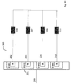
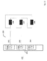
- each of the lighting devices should be arranged to receive the data flow and to set its variable bus address during the initialization phase unlike the other lighting devices of the lighting network and in contrast to the prior art, to ensure that the lighting devices to different proportions of Input data flow react. It is therefore particularly advantageous if each of the lighting devices has a device to generate a variable network address (bus address) itself, which preferably depends on the position in the lighting network. Exemplary methods for this are in DE-B-102 56 631 . EP-B-1 490 772 . EP-B-1 364 288 and / or in EP-A-2 571 200 disclosed.
- the control provides, for example, a bus address to all bus subscribers (lighting device) at the same time and the bus subscribers decide whether this bus address is suitable for the respective bus subscriber. If this decision is positive, the bus user accepts the provided bus address and signals to all other bus users that this bus address has been accepted or that now the assumption of the next bus address should be made by another bus participant.
- This signaling can take place, for example, by passing the data flow from said first data interface of the lighting device to said second data interface of the lighting device and vice versa from the time at which the variable bus address of the lighting device has been adopted.
- the bus address is not concretely assigned to a bus subscriber. It is thus the case that the controller provides the network - ie all bus users - with a bus address for (free) use. Individual bus participants decide independently according to this procedure whether they use this bus address. It is thus not an assignment with respect to a single bus participant, but the assignment of the bus address to a network position.
- the particular advantage of this method is that the individual bus users receive their bus address due to their position and do not have to be preconfigured.
- bus user may also be appropriate for the bus user to maintain the address table of all network addresses (bus addresses) of the lighting network used.
- the bus user selects one of the bus addresses independently, determined by the position in the cable harness.
Landscapes
- Circuit Arrangement For Electric Light Sources In General (AREA)
- Compression, Expansion, Code Conversion, And Decoders (AREA)
Priority Applications (4)
| Application Number | Priority Date | Filing Date | Title |
|---|---|---|---|
| EP14783571.4A EP3053410B1 (fr) | 2013-09-30 | 2014-09-30 | Procédé de génération d'une séquence de mots de code binaires d'un code multi-bits destiné à un signal de commande destiné à un consommateur |
| PCT/EP2014/070885 WO2015044442A2 (fr) | 2013-09-30 | 2014-09-30 | Procédé de génération d'une séquence de mots de code binaires d'un code multi-bits destiné à un signal de commande destiné à un consommateur |
| PCT/EP2014/070893 WO2015044447A2 (fr) | 2013-09-30 | 2014-09-30 | Dispositif d'éclairage |
| EP14780448.8A EP3053409B1 (fr) | 2013-09-30 | 2014-09-30 | Dispositif d'éclairage |
Applications Claiming Priority (1)
| Application Number | Priority Date | Filing Date | Title |
|---|---|---|---|
| DE102013016386.2A DE102013016386B4 (de) | 2013-09-30 | 2013-09-30 | Vorrichtung und Verfahren zur Einstellung mehrfarbiger Lichtszenen in Kfz |
Publications (1)
| Publication Number | Publication Date |
|---|---|
| EP2854482A1 true EP2854482A1 (fr) | 2015-04-01 |
Family
ID=50156595
Family Applications (4)
| Application Number | Title | Priority Date | Filing Date |
|---|---|---|---|
| EP14156035.9A Withdrawn EP2854483A1 (fr) | 2013-09-30 | 2014-02-20 | Dispositif d'éclairage |
| EP14155995.5A Withdrawn EP2854482A1 (fr) | 2013-09-30 | 2014-02-20 | Procédé de génération d'une séquence de mots de code binaires d'un code à bits multiples pour un signal de commande Pulse Modulated pour un consommateur |
| EP14780448.8A Active EP3053409B1 (fr) | 2013-09-30 | 2014-09-30 | Dispositif d'éclairage |
| EP14783571.4A Active EP3053410B1 (fr) | 2013-09-30 | 2014-09-30 | Procédé de génération d'une séquence de mots de code binaires d'un code multi-bits destiné à un signal de commande destiné à un consommateur |
Family Applications Before (1)
| Application Number | Title | Priority Date | Filing Date |
|---|---|---|---|
| EP14156035.9A Withdrawn EP2854483A1 (fr) | 2013-09-30 | 2014-02-20 | Dispositif d'éclairage |
Family Applications After (2)
| Application Number | Title | Priority Date | Filing Date |
|---|---|---|---|
| EP14780448.8A Active EP3053409B1 (fr) | 2013-09-30 | 2014-09-30 | Dispositif d'éclairage |
| EP14783571.4A Active EP3053410B1 (fr) | 2013-09-30 | 2014-09-30 | Procédé de génération d'une séquence de mots de code binaires d'un code multi-bits destiné à un signal de commande destiné à un consommateur |
Country Status (3)
| Country | Link |
|---|---|
| EP (4) | EP2854483A1 (fr) |
| DE (1) | DE102013016386B4 (fr) |
| WO (2) | WO2015044447A2 (fr) |
Families Citing this family (8)
| Publication number | Priority date | Publication date | Assignee | Title |
|---|---|---|---|---|
| DE102014014678B4 (de) | 2014-09-29 | 2020-08-06 | Elmos Semiconductor Aktiengesellschaft | Vorrichtung zur Erzeugung von PWM-modulierten Signalen für die Versorgung von LEDs für die Beleuchtung in Kfz |
| DE102014014679B4 (de) | 2014-09-29 | 2020-12-03 | Elmos Semiconductor Se | Vorrichtung zur Erzeugung von PDM-modulierten Signalen für die Versorgung von LEDs für die Beleuchtung in Kfz |
| DE102014014677B4 (de) | 2014-09-29 | 2023-08-31 | Elmos Semiconductor Se | Verfahren zur Erzeugung von PDM-modulierten Signalen für die Versorgung von LEDs für die Beleuchtung in Kfz |
| DE102014014680B4 (de) | 2014-09-29 | 2020-08-06 | Elmos Semiconductor Aktiengesellschaft | Verfahren zur Erzeugung von PWM-modulierten Signalen für die Versorgung von LEDs für die Beleuchtung in Kfz |
| EP3258748A1 (fr) | 2016-06-13 | 2017-12-20 | Melexis Technologies NV | Boîtier de diodes électroluminescentes |
| DE102016211737A1 (de) * | 2016-06-29 | 2018-01-04 | Bayerische Motoren Werke Aktiengesellschaft | Kraftfahrzeug |
| EP3324437B1 (fr) | 2016-11-16 | 2019-03-13 | Melexis Technologies NV | Dispositif à diodes électroluminescentes |
| EP3937594B1 (fr) * | 2020-07-10 | 2025-11-12 | Big Dutchman International GmbH | Commande lumineuse à canaux multiples |
Citations (5)
| Publication number | Priority date | Publication date | Assignee | Title |
|---|---|---|---|---|
| WO2009040705A2 (fr) * | 2007-09-28 | 2009-04-02 | Koninklijke Philips Electronics N.V. | Procédé et appareil pour une commande d'intensité de lumière avec une modulation de courant de commande |
| US20100109550A1 (en) * | 2008-11-03 | 2010-05-06 | Muzahid Bin Huda | LED Dimming Techniques Using Spread Spectrum Modulation |
| DE112008003651T5 (de) * | 2008-01-30 | 2011-03-03 | Mitsubishi Electric Corp. | Codewandlervorrichtung, Empfänger und Codeumwandlungsverfahren |
| US8129924B2 (en) * | 2006-11-13 | 2012-03-06 | Cypress Semiconductor Corporation | Stochastic signal density modulation for optical transducer control |
| EP2696657A2 (fr) * | 2012-08-10 | 2014-02-12 | Infineon Technologies AG | Modulateur à quantification variable |
Family Cites Families (18)
| Publication number | Priority date | Publication date | Assignee | Title |
|---|---|---|---|---|
| US6016038A (en) | 1997-08-26 | 2000-01-18 | Color Kinetics, Inc. | Multicolored LED lighting method and apparatus |
| US6362766B1 (en) * | 2000-02-09 | 2002-03-26 | International Business Machines Corporation | Variable pulse PWM DAC method and apparatus |
| FR2821453B1 (fr) | 2001-02-26 | 2005-07-08 | Valeo Climatisation | Procede d'identification des noeuds d'un reseau informatif dans une installation de climatisation de vehicule automobile, et installation de climatisation faisant application du procede |
| WO2003094001A1 (fr) | 2002-05-02 | 2003-11-13 | Elmos Semiconductor Ag | Procede d'adressage de dispositifs utilisateurs d'un systeme a bus au moyen de courants d'identification |
| DE10256631B4 (de) | 2002-12-03 | 2005-07-14 | Elmos Semiconductor Ag | Verfarhen zur Adressierung der Teilnehmer eines Bussystems |
| WO2007104154A1 (fr) * | 2006-03-14 | 2007-09-20 | Tir Technology Lp | Appareil et procédé de commande d'activation d'un dispositif électronique |
| US8494367B2 (en) * | 2006-06-28 | 2013-07-23 | Koninklijke Philips Electronics N.V. | Method and device for modulating the light emission of a lighting device |
| US7915838B2 (en) * | 2007-06-29 | 2011-03-29 | Cypress Semiconductor Corporation | Delta-sigma signal density modulation for optical transducer control |
| CN101990786A (zh) * | 2008-01-17 | 2011-03-23 | 皇家飞利浦电子股份有限公司 | 用于光强度控制的方法和装置 |
| WO2009136723A2 (fr) * | 2008-05-07 | 2009-11-12 | 주식회사 테라칩스 | Dispositif et procédé de commande de modulation d'impulsion en durée répartie |
| WO2009136317A1 (fr) * | 2008-05-08 | 2009-11-12 | Koninklijke Philips Electronics N.V. | Procédé et appareil pour un étalement de spectre par la juxtaposition temporelle de signaux pulsés |
| GB2465194A (en) * | 2008-11-10 | 2010-05-12 | Iti Scotland Ltd | Randomly or pseudo-randomly modulated switching waveform for LED backlight |
| EP2257131A1 (fr) * | 2009-05-29 | 2010-12-01 | Koninklijke Philips Electronics N.V. | Procédé d'auto-adressage pour système d'éclairage à carreaux |
| US20120127210A1 (en) * | 2010-11-19 | 2012-05-24 | Au Optronics Corporation | Random PWM Dimming Control for LED Backlight |
| US8558497B2 (en) * | 2011-07-15 | 2013-10-15 | Cypress Semiconductor Corporation | Reduced electromagnetic interference for pulse-width modulation |
| US8935450B2 (en) | 2011-09-16 | 2015-01-13 | Nxp B.V. | Network communications circuit, system and method |
| EP2631674A1 (fr) | 2012-02-23 | 2013-08-28 | ELMOS Semiconductor AG | Procédé et système de capteur destinés à la mesure des propriétés d'une voie de transmission d'un système de mesure entre émetteur et récepteur |
| EP2688209A1 (fr) | 2012-07-16 | 2014-01-22 | Siemens Aktiengesellschaft | Circuits d'excitation et commandes pour un circuit d'excitation |
-
2013
- 2013-09-30 DE DE102013016386.2A patent/DE102013016386B4/de active Active
-
2014
- 2014-02-20 EP EP14156035.9A patent/EP2854483A1/fr not_active Withdrawn
- 2014-02-20 EP EP14155995.5A patent/EP2854482A1/fr not_active Withdrawn
- 2014-09-30 WO PCT/EP2014/070893 patent/WO2015044447A2/fr not_active Ceased
- 2014-09-30 EP EP14780448.8A patent/EP3053409B1/fr active Active
- 2014-09-30 EP EP14783571.4A patent/EP3053410B1/fr active Active
- 2014-09-30 WO PCT/EP2014/070885 patent/WO2015044442A2/fr not_active Ceased
Patent Citations (5)
| Publication number | Priority date | Publication date | Assignee | Title |
|---|---|---|---|---|
| US8129924B2 (en) * | 2006-11-13 | 2012-03-06 | Cypress Semiconductor Corporation | Stochastic signal density modulation for optical transducer control |
| WO2009040705A2 (fr) * | 2007-09-28 | 2009-04-02 | Koninklijke Philips Electronics N.V. | Procédé et appareil pour une commande d'intensité de lumière avec une modulation de courant de commande |
| DE112008003651T5 (de) * | 2008-01-30 | 2011-03-03 | Mitsubishi Electric Corp. | Codewandlervorrichtung, Empfänger und Codeumwandlungsverfahren |
| US20100109550A1 (en) * | 2008-11-03 | 2010-05-06 | Muzahid Bin Huda | LED Dimming Techniques Using Spread Spectrum Modulation |
| EP2696657A2 (fr) * | 2012-08-10 | 2014-02-12 | Infineon Technologies AG | Modulateur à quantification variable |
Non-Patent Citations (1)
| Title |
|---|
| CLAVIER A G ET AL: "Distortion in a Pulse Count Modulation System", TRANSACTIONS OF THE AMERICAN INSTITUTE OF ELECTRICAL ENGINEERS, AMERICAN INSTITUTE OF ELECTRICAL ENGINEERS, NEW YORK, NY, US, vol. 66, no. 1, 1 January 1947 (1947-01-01), pages 989 - 1005, XP011294078, ISSN: 0096-3860 * |
Also Published As
| Publication number | Publication date |
|---|---|
| DE102013016386A1 (de) | 2015-04-02 |
| WO2015044442A3 (fr) | 2015-08-13 |
| WO2015044447A3 (fr) | 2015-08-13 |
| EP3053410A2 (fr) | 2016-08-10 |
| EP3053409A2 (fr) | 2016-08-10 |
| EP3053409B1 (fr) | 2019-08-28 |
| WO2015044442A2 (fr) | 2015-04-02 |
| EP3053410B1 (fr) | 2021-08-04 |
| DE102013016386B4 (de) | 2025-03-20 |
| EP2854483A1 (fr) | 2015-04-01 |
| WO2015044447A2 (fr) | 2015-04-02 |
Similar Documents
| Publication | Publication Date | Title |
|---|---|---|
| EP3053410B1 (fr) | Procédé de génération d'une séquence de mots de code binaires d'un code multi-bits destiné à un signal de commande destiné à un consommateur | |
| DE102011076692B4 (de) | Pulsmodulationsanordnung und pulsmodulationsverfahren | |
| EP3536127B1 (fr) | Dispositif d'éclairage et système d'éclairage pour véhicule à moteur, et procédé pour faire fonctionner un système d'éclairage destiné à un véhicule à moteur | |
| EP1696707A2 (fr) | Luminaire | |
| EP2433472B1 (fr) | Procédé de réglage d'un point de couleur | |
| DE102017125405B4 (de) | Verfahren und Vorrichtung zum Kalibrieren und Betreiben einer RGB-LED-Beleuchtung | |
| WO2015074891A1 (fr) | Commande d'un moyen d'éclairage comportant au moins deux sources de lumière à semi-conducteur | |
| EP3453229A1 (fr) | Dispositif d'éclairage | |
| EP2508046B1 (fr) | Émission de signaux optiques de paramètres de fonctionnement d'un éclairage à del | |
| DE202005020801U1 (de) | Leuchte | |
| EP3072358A1 (fr) | Commande d'un moyen d'éclairage comprenant au moins deux sources de lumière à semi-conducteur | |
| DE10357776B4 (de) | Steueranordnung mit Leuchtdioden | |
| EP4156864B1 (fr) | Alimentation de puissance à del | |
| DE102015009736A1 (de) | Leuchtmodul und Leuchtsystem | |
| EP2772120B1 (fr) | Atténuation de moyens d'éclairage par modulation d'impulsions en largeur pwm | |
| DE102009026612A1 (de) | Ansteuerung eines Verbrauchers mit einem Rauschsignal | |
| DE102010039827A1 (de) | Verfahren zum Betreiben mindestens einer Leuchtdiode und Leuchtvorrichtung zum Durchführen des Verfahrens | |
| DE102016105739B4 (de) | Vorrichtung mit galvanischer Trennung von einem Kommunikationsbus für mehrere Kommunikationsstandards und entsprechendes Verfahren zur Datenübertragung über eine solche Vorrichtung | |
| EP3965533A1 (fr) | Module d'extension de mécanisme extracteur permettant de mettre à niveau un mécanisme extracteur | |
| DE102018201365A1 (de) | Schaltungsanordnung zum betreiben mindestens zweier led-stränge an einer spannung | |
| DE102019101234A1 (de) | PWM-Dimmen mit reduzierten hörbaren Geräuschen | |
| DE102012018760A1 (de) | Vorrichtung zum Betreiben von LEDs | |
| DE202017002443U1 (de) | Schaltungsanordnung zum Betreiben eines Leuchtmittels | |
| DE102021005158A1 (de) | LED-Leistungsversorgung | |
| EP3965365A1 (fr) | Module de base d'une constitution de réseau, ainsi que constitution de réseau et procédé de configuration d'un module d'extension de la constitution de réseau |
Legal Events
| Date | Code | Title | Description |
|---|---|---|---|
| PUAI | Public reference made under article 153(3) epc to a published international application that has entered the european phase |
Free format text: ORIGINAL CODE: 0009012 |
|
| 17P | Request for examination filed |
Effective date: 20140220 |
|
| AK | Designated contracting states |
Kind code of ref document: A1 Designated state(s): AL AT BE BG CH CY CZ DE DK EE ES FI FR GB GR HR HU IE IS IT LI LT LU LV MC MK MT NL NO PL PT RO RS SE SI SK SM TR |
|
| AX | Request for extension of the european patent |
Extension state: BA ME |
|
| RAP1 | Party data changed (applicant data changed or rights of an application transferred) |
Owner name: ELMOS SEMICONDUCTOR AKTIENGESELLSCHAFT |
|
| STAA | Information on the status of an ep patent application or granted ep patent |
Free format text: STATUS: THE APPLICATION IS DEEMED TO BE WITHDRAWN |
|
| RAP1 | Party data changed (applicant data changed or rights of an application transferred) |
Owner name: ELMOS SEMICONDUCTOR AKTIENGESELLSCHAFT |
|
| 18D | Application deemed to be withdrawn |
Effective date: 20151002 |