EP2508046B1 - Émission de signaux optiques de paramètres de fonctionnement d'un éclairage à del - Google Patents
Émission de signaux optiques de paramètres de fonctionnement d'un éclairage à del Download PDFInfo
- Publication number
- EP2508046B1 EP2508046B1 EP10790377.5A EP10790377A EP2508046B1 EP 2508046 B1 EP2508046 B1 EP 2508046B1 EP 10790377 A EP10790377 A EP 10790377A EP 2508046 B1 EP2508046 B1 EP 2508046B1
- Authority
- EP
- European Patent Office
- Prior art keywords
- light
- operating device
- intended
- leds
- emission
- Prior art date
- Legal status (The legal status is an assumption and is not a legal conclusion. Google has not performed a legal analysis and makes no representation as to the accuracy of the status listed.)
- Active
Links
Images
Classifications
-
- H—ELECTRICITY
- H05—ELECTRIC TECHNIQUES NOT OTHERWISE PROVIDED FOR
- H05B—ELECTRIC HEATING; ELECTRIC LIGHT SOURCES NOT OTHERWISE PROVIDED FOR; CIRCUIT ARRANGEMENTS FOR ELECTRIC LIGHT SOURCES, IN GENERAL
- H05B47/00—Circuit arrangements for operating light sources in general, i.e. where the type of light source is not relevant
- H05B47/20—Responsive to malfunctions or to light source life; for protection
- H05B47/21—Responsive to malfunctions or to light source life; for protection of two or more light sources connected in parallel
- H05B47/22—Responsive to malfunctions or to light source life; for protection of two or more light sources connected in parallel with communication between the lamps and a central unit
-
- H—ELECTRICITY
- H05—ELECTRIC TECHNIQUES NOT OTHERWISE PROVIDED FOR
- H05B—ELECTRIC HEATING; ELECTRIC LIGHT SOURCES NOT OTHERWISE PROVIDED FOR; CIRCUIT ARRANGEMENTS FOR ELECTRIC LIGHT SOURCES, IN GENERAL
- H05B45/00—Circuit arrangements for operating light-emitting diodes [LED]
- H05B45/20—Controlling the colour of the light
-
- H—ELECTRICITY
- H05—ELECTRIC TECHNIQUES NOT OTHERWISE PROVIDED FOR
- H05B—ELECTRIC HEATING; ELECTRIC LIGHT SOURCES NOT OTHERWISE PROVIDED FOR; CIRCUIT ARRANGEMENTS FOR ELECTRIC LIGHT SOURCES, IN GENERAL
- H05B47/00—Circuit arrangements for operating light sources in general, i.e. where the type of light source is not relevant
- H05B47/10—Controlling the light source
- H05B47/175—Controlling the light source by remote control
- H05B47/198—Grouping of control procedures or address assignation to light sources
- H05B47/1985—Creation of lighting zones or scenes
Definitions
- the present invention relates to methods for optical signal output of operating parameters in an operating device with an LED light source controlled by the latter, which is formed by at least three LEDs, which are individually intended for the emission of light of different colors and together for the emission of white cumulative light.
- an LED for emitting light of a color is “determined”, this is to mean that the LED can only produce light of that color.
- This operating address may differ from an optionally provided by the manufacturer's source address in the device.
- each bus subscriber will be assigned an operating address, or each bus subscriber has himself assigned an address from the defined address supply.
- it In order to be able to proceed in a targeted manner in the following actual operation of the lighting system controlled by means of the bus system, it must be learned how the operating address of each connected bus subscriber is. This takes a long time since an operator must physically go to each connected bus subscriber to then typically visually inspect address assignment in place.
- this installation step is particularly cumbersome if the bus subscribers are widely distributed in a building or possibly over several buildings.
- so-called emergency lighting devices which, if a mains voltage supply is battery-powered, thus ensure a defined emergency lighting and which are usually distributed particularly widely spaced from each other over buildings. If, therefore, the installer has to move over large areas of the installation area, especially in the case of emergency lighting devices, then at least the in-experience of the assigned addresses should proceed as swiftly as possible.
- the WO 2006/136236 starts at this point and proposes to provide, in addition to the light source controlled by the operating device, additional optical and / or acoustic signal transmitters which can reproduce the bus address in coded form.
- additional optical and / or acoustic signal transmitters which can reproduce the bus address in coded form.
- an acoustic signal generator for example LEDs can be used, which are preferably connected to the operating device.
- the EP 1 098 550 A2 discloses the possibility of reducing the hardware complexity compared to the prior art described last, in the case of optical indication of the operating time of an operating device. This is achieved by driving the LED light source forming RGB LEDs, which are intended for the emission of monochrome (non-white) light, for the optical signal output of the operating time.
- the inventive solution additional optical and / or acoustic signal generators are dispensable for the reliable display of the result of a self-test of the operating device.
- the invention relates to a lighting arrangement according to claim 8.
- the invention relating to the lighting arrangement has the same object and the same solution principle as the invention relating to the method described above. The corresponding statements are therefore made to avoid repetition.
- the LEDs selected for signal output should be intended to emit a selected color, but they need not and may also emit a non-monochromatic mixed color. It is essential that the selected LEDs emit a non-white light total light, which differs clearly in terms of its color from the white light that is intended to emit the LED light source intended for the illumination of their environment.
- the LED light source may consist of three LEDs, one of which is intended to emit red light, a second to emit green light and a third to emit blue light.
- At least one specific for the emission of monochromatic light LED is controlled so that it transmits information, for example, after the Morse code by short and long illumination.
- Another variant may be that the LEDs intended for the emission of colored light and forming a subgroup are driven in such a way that they Represent numbers, digits or other symbols, by means of which the signal output is realized.
- the inventions are suitable for displaying an originating address or an operating address of an operating device for the LED light source or another light source.
- the operating device from a remote control center - possibly via a bus system - are called for a signal transmission.
- the invention also relates to a lighting system, comprising at least two lighting arrangements controlled via a bus line, for example according to the DALI standard, and preferably connected to a central unit.
- each lighting arrangement can be assigned an individual and / or a group address, wherein the light signals representing the particular operating parameters reproduce the allocated address of the associated lighting arrangement.
- Different addresses can be reproduced by light signals of different spectrum, in particular different color.
- the output of the assigned address by means of the light signals may be triggered by a command from the central processing unit or by a manual user activity.
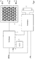
- the only figure shows a lighting arrangement with a gas discharge lamp, a ballast for this, and an emergency light module with LED light source, all controlled by a (not shown) center of a bus system.
- the sole FIGURE shows an electronic ballast which controls a gas discharge lamp 2 for illuminating an unspecified space.
- the ballast 1 draws its electrical energy from the network.
- an emergency light module 3 fed by a battery 5 becomes active and sets an LED light source 4 into operation.
- the latter is particularly well suited for emergency lighting operation, because it can be operated with low voltage, in contrast to the gas discharge lamp 2, so that conversion losses are eliminated.
- the energy efficiency of the LED light source 4 is cheaper than that of the gas discharge lamp 2, which is an important factor in battery operation.
- Such an operating parameter can be, for example, the result of a self-test of the emergency light module 3, which can be initiated by pressing a button 6 provided on the emergency light module 3.
- the self-test may, for example, refer to the state of the battery of the emergency light module.
- the optically output operating parameters can indicate operating states and / or errors of the light source.
- a self-test can be carried out beforehand by the operating device, which is triggered by an internal control and / or by external signals can be.
- An example of an error indication is an exceeding and / or falling below of a limit value by the (mains) supply voltage.
- operating data such as the number or duration of operation of the light source or a component aging can be displayed.
- These parameters can be determined by means of a counter and / or by means of this parameter determined measuring circuit, wherein the measuring circuit can perform a monitoring measurement.
- the LED light source 4 is a white light source. In the present example, it consists of three groups of LEDs. The LEDs 4a of the first group are intended to emit red light. The LEDs 4b of the second group are intended to emit blue light. And the LEDs 4c of the third group are for emitting green light. If the LEDs 4a, 4b, 4c of all three groups are driven by the emergency light module 3 for light emission, then the cumulative light emitted by them is white as intended.
- the display of the operating parameters takes place in the present case in that only a partial number of the LEDs of the LED light source is driven for the optical signal output, the way that they differ from a regular one Illuminate monochrome light or also a buzzing mixed light, which is not white.
- one or more LEDs 4c can be controlled, which are intended for the emission of monochrome green light.
- one or more LEDs 4a which are intended to emit red light, can be actuated.
- An address may be conveyed by one or more selected LEDs destined to emit one of the three colors being driven to flash / blink.
- the blinking can take place in short or long luminous phases, so that the information is transmitted, for example, with the Morse code.
- the LED light source instead of producing white light by triples of LEDs 4a, 4b, 4c designed to emit red, blue and green light, it is also possible for the LED light source to consist of only two groups of LEDs together, one of which comprises color-converted white light LEDs, and the other one for monochromatic red light emission, which supplement the color spectrum of the white light LEDs to produce a white sum light that is closer to room lighting requirements than the white light emitted only by the white light LEDs. Because white light is not monochromatic, there are many variants of it. It is important in this context that the LEDs which are intended for the emission of red light are activated for the signal output.
Landscapes
- Circuit Arrangement For Electric Light Sources In General (AREA)
- Non-Portable Lighting Devices Or Systems Thereof (AREA)
Claims (10)
- Procédé pour sortie par signal optique de paramètres de fonctionnement dans un appareil de contrôle (3) comprenant une source de lumière LED (4) commandée par cet appareil de contrôle (3), composée d'au moins trois LED (4a, 4b, 4c),
les au moins trois LED étant destinées individuellement à l'émission d'une lumière de différente couleur et ensemble à l'émission d'une lumière globale blanche, une partie des LED (4a, 4b, 4c) formant la source de lumière LED (4) étant destinée à l'émission d'une lumière non blanche et cette partie comprenant au moins deux LED non blanches destinées à l'émission de lumière monochrome, au moins une des au moins deux LED non blanches (4a) étant destinée à l'émission de lumière rouge et au moins une des au moins deux LED non blanches (4c) étant destinée à l'émission de lumière verte,
l'appareil de contrôle commandant les au moins deux LED non blanches pour la sortie par signal optique de paramètres de fonctionnement de l'appareil de contrôle, la sortie par signal optique étant réalisée par le clignotement des au moins deux LED non blanches (4a, 4b, 4c),
caractérisé en ce
qu'un des paramètres de fonctionnement à afficher est un résultat d'un autotest de l'appareil de contrôle (3),
un résultat positif de l'autotest de l'appareil de contrôle (3) étant réalisé par le clignotement de l'au moins une LED (4c) destinée à l'émission de lumière verte,
et un résultat négatif de l'autotest de l'appareil de contrôle (3), c'est-à-dire un état défectueux, étant réalisé par le clignotement de l'au moins une LED (4a) destinée à l'émission de lumière rouge. - Procédé selon la revendication 1,
d'autres paramètres de fonctionnement à afficher étant choisi parmi :- états défectueux concernant la tension d'alimentation, et/ou- tensions à un composant de l'appareil de contrôle, tel que, p. ex., une tension de batterie. - Procédé selon l'une quelconque des revendications 1 ou 2, la source de lumière LED (4) étant utilisée aussi, outre pour la sortie par signal optique, pour l'éclairage, en particulier pour l'éclairage de secours.
- Procédé selon l'une quelconque des revendications précédentes,
caractérisé en ce
que la sortie par signal optique est réalisée de préférence par une modulation cadencée des au moins deux LED non blanches (4a, 4b, 4c) destinées à l'émission de lumière monochrome. - Procédé selon la revendication 1, caractérisé en ce qu'un autre paramètre de fonctionnement à afficher est une adresse source ou une adresse de service, à travers laquelle l'appareil de contrôle (3) peut être appelé à partir d'une centrale éloignée, le cas échéant à travers un système de bus.
- Dispositif d'éclairage comprenant un appareil de contrôle (3) et comprenant une source de lumière LED (4) commandée par cet appareil de contrôle, composée d'au moins trois LED (4a, 4b, 4c),
les au moins trois LED émettant individuellement de la lumière de couleur différente et ensemble une lumière globale blanche,
une partie des LED (4a, 4b, 4c) formant la source de lumière LED (4) étant destinée à l'émission d'une lumière non blanche et cette partie comprenant au moins deux LED non blanches destinées à l'émission de lumière monochrome, au moins une des au moins deux LED non blanches (4a) étant destinée à l'émission de lumière rouge et au moins une des au moins deux LED non blanches (4c) étant destinée à l'émission de lumière verte, et
l'appareil de contrôle (3) étant conçu pour commander les au moins deux LED non blanches de telle façon que celles-ci émettent des signaux lumineux représentant des paramètres de fonctionnement de l'appareil de contrôle (3), l'émission des signaux lumineux étant réalisée par le clignotement des au moins deux LED non blanches (4a, 4b, 4c),
caractérisé en ce
que l'appareil de contrôle (3) est conçu pour afficher un résultat d'autotest de l'appareil de contrôle en tant qu'un des paramètres de fonctionnement,
un résultat positif de l'autotest de l'appareil de contrôle (3) étant réalisé par le clignotement de l'au moins une LED (4c) destinée à l'émission de lumière verte, et un résultat négatif de l'autotest de l'appareil de contrôle (3), c'est-à-dire un état défectueux, étant réalisé par le clignotement de l'au moins une LED (4a) destinée à l'émission de lumière rouge. - Système d'éclairage,
comprenant au moins deux dispositifs selon la revendication 6 commandés à travers une ligne de bus ou conformément au standard DALI et connectés de préférence à une unité centrale. - Système d'éclairage selon la revendication 7,
chaque dispositif d'éclairage étant conçu pour être attribué une adresse individuelle et/ou une adresse de groupe, les signaux lumineux représentant des paramètres de fonctionnement définis reproduisant l'adresse attribuée du dispositif d'éclairage associé. - Système d'éclairage selon la revendication 8,
les signaux lumineux représentant des paramètres de fonctionnement définis reproduisant des adresses différentes par des signaux lumineux de spectres différents, en particulier de couleurs différentes. - Système d'éclairage selon l'une quelconque des revendications 8 ou 9,
le système d'éclairage étant conçu pour déclencher la sortie de l'adresse attribuée au moyen des signaux lumineux par une commande d'une unité centrale du système d'éclairage ou par une activité manuelle d'utilisateur.
Applications Claiming Priority (4)
| Application Number | Priority Date | Filing Date | Title |
|---|---|---|---|
| DE102009057015 | 2009-12-04 | ||
| DE102009055415 | 2009-12-30 | ||
| DE102010000902A DE102010000902A1 (de) | 2009-12-04 | 2010-01-14 | Optische Signalausgabe von Betriebsparametern bei einer LED-Beleuchtung |
| PCT/EP2010/068803 WO2011067367A2 (fr) | 2009-12-04 | 2010-12-03 | Émission de signaux optiques de paramètres de fonctionnement d'un éclairage à del |
Publications (2)
| Publication Number | Publication Date |
|---|---|
| EP2508046A2 EP2508046A2 (fr) | 2012-10-10 |
| EP2508046B1 true EP2508046B1 (fr) | 2019-04-03 |
Family
ID=43972455
Family Applications (1)
| Application Number | Title | Priority Date | Filing Date |
|---|---|---|---|
| EP10790377.5A Active EP2508046B1 (fr) | 2009-12-04 | 2010-12-03 | Émission de signaux optiques de paramètres de fonctionnement d'un éclairage à del |
Country Status (5)
| Country | Link |
|---|---|
| US (1) | US8901822B2 (fr) |
| EP (1) | EP2508046B1 (fr) |
| CN (1) | CN102668715B (fr) |
| DE (2) | DE102010000902A1 (fr) |
| WO (1) | WO2011067367A2 (fr) |
Families Citing this family (7)
| Publication number | Priority date | Publication date | Assignee | Title |
|---|---|---|---|---|
| AT510826B1 (de) * | 2010-11-10 | 2016-05-15 | Din Dietmar Nocker Facilityman Gmbh | Verfahren zur initialisierung einer notbeleuchtungsanlage |
| US9167674B2 (en) | 2012-04-19 | 2015-10-20 | Cooper Technologies Company | Emergency battery converter |
| US9328883B1 (en) * | 2012-05-07 | 2016-05-03 | Cooper Technologies Company | Providing power to remote emergency light fixtures |
| DE102015217398B4 (de) | 2015-09-11 | 2025-08-28 | Tridonic Gmbh & Co Kg | Belechtungsanordnung, Beleuchtungssystem und Verfahren zum Betreiben eines Beleuchtungssystems für einen Gebäudeteil |
| DE102020100399A1 (de) * | 2020-01-10 | 2021-07-15 | Zumtobel Lighting Gmbh | Leuchte mit integriertem Selbsttest |
| CN116634254A (zh) * | 2022-02-11 | 2023-08-22 | 深超光电(深圳)有限公司 | 成像系统及光学装置 |
| CN116453272A (zh) * | 2023-03-31 | 2023-07-18 | 江苏海马通信科技有限公司 | 基于物联网技术的遥控双语智能信号灯 |
Citations (5)
| Publication number | Priority date | Publication date | Assignee | Title |
|---|---|---|---|---|
| EP1098550A2 (fr) * | 1999-11-05 | 2001-05-09 | Avix Inc. | Lampe à diodes Led |
| GB2432951A (en) * | 2003-09-19 | 2007-06-06 | Saf T Glo Ltd | Networked devices which perform self test check |
| WO2010086758A1 (fr) * | 2009-02-02 | 2010-08-05 | Koninklijke Philips Electronics, N.V. | Système d'avertissement codé pour unités d'éclairage |
| WO2010116289A1 (fr) * | 2009-04-08 | 2010-10-14 | Koninklijke Philips Electronics N.V. | Dispositif d'éclairage avec indication d'état par lumière modulée |
| WO2013089659A2 (fr) * | 2010-10-22 | 2013-06-20 | Cree, Inc. | Dispositifs d'éclairage à semi-conducteurs générant des signaux d'alerte visibles dans des applications d'éclairage générales et procédés de fonctionnement associés |
Family Cites Families (13)
| Publication number | Priority date | Publication date | Assignee | Title |
|---|---|---|---|---|
| CN2397559Y (zh) * | 1999-11-24 | 2000-09-20 | 稳态企业有限公司 | 具光影变化的多功能广告牌 |
| US7642730B2 (en) * | 2000-04-24 | 2010-01-05 | Philips Solid-State Lighting Solutions, Inc. | Methods and apparatus for conveying information via color of light |
| US7397068B2 (en) * | 2003-12-23 | 2008-07-08 | Tessera, Inc. | Solid state lighting device |
| CA2496661C (fr) * | 2004-02-19 | 2009-05-19 | Oz Optics Ltd. | Systeme de commande de source lumineuse |
| US7592713B2 (en) * | 2005-02-25 | 2009-09-22 | Marathon Coach, Inc. | Electrical system for controlling coach resources |
| DE102005028206B4 (de) | 2005-06-17 | 2018-05-17 | Tridonic Gmbh & Co Kg | Ermittlung der Busadresse eines Teilnehmers in einem Beleuchtungs-Bussystem |
| DE102005057068A1 (de) * | 2005-11-30 | 2007-06-06 | Zumtobel Lighting Gmbh | Steuerungssystem für mehrere verteilt angeordnete Verbraucher, insbesondere für Lampenbetriebsgeräte, sowie Verfahren zur Inbetriebnahme |
| EP1989925A1 (fr) | 2006-02-23 | 2008-11-12 | TIR Technology LP | Système et procédé d'identification d'une source lumineuse |
| US7737640B2 (en) * | 2007-02-12 | 2010-06-15 | Abl Ip Holding Llc | Emergency lighting system |
| CN201059430Y (zh) * | 2007-03-13 | 2008-05-14 | 士商(上海)机械有限公司 | Led工作灯 |
| DE202007005495U1 (de) * | 2007-04-13 | 2007-08-30 | Werma Signaltechnik Gmbh + Co. Kg | Warnleuchtsäule |
| DE102007052377B4 (de) * | 2007-10-31 | 2015-04-02 | Werma Holding Gmbh + Co. Kg | Warnleuchte zur optischen Anzeige von wenigstens einem Betriebszustand |
| KR20110101915A (ko) * | 2010-03-10 | 2011-09-16 | 한국원자력연구원 | 축전지의 잔여용량 지시기능을 갖는 유도등 및 비상조명등 |
-
2010
- 2010-01-14 DE DE102010000902A patent/DE102010000902A1/de not_active Withdrawn
- 2010-12-03 WO PCT/EP2010/068803 patent/WO2011067367A2/fr not_active Ceased
- 2010-12-03 CN CN201080054153.4A patent/CN102668715B/zh not_active Expired - Fee Related
- 2010-12-03 DE DE112010004654T patent/DE112010004654A5/de not_active Ceased
- 2010-12-03 EP EP10790377.5A patent/EP2508046B1/fr active Active
- 2010-12-03 US US13/513,358 patent/US8901822B2/en active Active
Patent Citations (6)
| Publication number | Priority date | Publication date | Assignee | Title |
|---|---|---|---|---|
| EP1098550A2 (fr) * | 1999-11-05 | 2001-05-09 | Avix Inc. | Lampe à diodes Led |
| GB2432951A (en) * | 2003-09-19 | 2007-06-06 | Saf T Glo Ltd | Networked devices which perform self test check |
| WO2010086758A1 (fr) * | 2009-02-02 | 2010-08-05 | Koninklijke Philips Electronics, N.V. | Système d'avertissement codé pour unités d'éclairage |
| WO2010116289A1 (fr) * | 2009-04-08 | 2010-10-14 | Koninklijke Philips Electronics N.V. | Dispositif d'éclairage avec indication d'état par lumière modulée |
| WO2013089659A2 (fr) * | 2010-10-22 | 2013-06-20 | Cree, Inc. | Dispositifs d'éclairage à semi-conducteurs générant des signaux d'alerte visibles dans des applications d'éclairage générales et procédés de fonctionnement associés |
| EP2636285A2 (fr) * | 2010-10-22 | 2013-09-11 | Cree, Inc. | Dispositifs d'éclairage à semi-conducteurs générant des signaux d'alerte visibles dans des applications d'éclairage générales et procédés de fonctionnement associés |
Also Published As
| Publication number | Publication date |
|---|---|
| DE102010000902A1 (de) | 2011-06-09 |
| US20130043794A1 (en) | 2013-02-21 |
| US8901822B2 (en) | 2014-12-02 |
| CN102668715B (zh) | 2015-09-30 |
| EP2508046A2 (fr) | 2012-10-10 |
| WO2011067367A2 (fr) | 2011-06-09 |
| CN102668715A (zh) | 2012-09-12 |
| WO2011067367A3 (fr) | 2011-08-11 |
| DE112010004654A5 (de) | 2012-10-31 |
Similar Documents
| Publication | Publication Date | Title |
|---|---|---|
| EP2508046B1 (fr) | Émission de signaux optiques de paramètres de fonctionnement d'un éclairage à del | |
| DE4327809C2 (de) | Verfahren zum Adressieren von mit einer zentralen Steuereinheit verbundenen elektronischen Vorschaltgeräten | |
| DE102008061089B4 (de) | Adressvergabe für busfähige Leuchtmittel-Betriebsgeräte, insbesondere für LEDs | |
| EP1555859A1 (fr) | Commande des dispositifsd'éclairage par des signaux modulés sur bus à courant continu | |
| DE102009050733A1 (de) | Verfahren und System zur Vergabe von Betriebsadressen für Lichtquellen oder Leuchten | |
| EP1587347B1 (fr) | Dispositif pour contrôler une pluralité de luminaires | |
| DE102013016386B4 (de) | Vorrichtung und Verfahren zur Einstellung mehrfarbiger Lichtszenen in Kfz | |
| EP2659735A1 (fr) | Dispositif de signalisation et dispositif de détection | |
| DE102008056164A1 (de) | Zuweisung einer Betriebsadresse an ein busfähiges Betriebsgerät für Leuchtmittel | |
| WO2009040014A1 (fr) | Procédé de configuration d'un système de bus d'éclairage | |
| EP1891838B1 (fr) | Determination de l'adresse de bus d'un element connecte dans un systeme de bus d'eclairage | |
| EP1665903A1 (fr) | Systeme de commande pour plusieurs dispositifs de commande d'ampoule repartis, et procede d'initialisation d'un tel systeme de commande | |
| EP2553674A1 (fr) | Procédé d'éclairage d'un caisson lumineux | |
| DE102009024412A1 (de) | Verfahren zum Betreiben eines Beleuchtungssystems, Computerprogramm und Beleuchtungssystem | |
| EP2176584B1 (fr) | Appareil d'éclairage pourvu d'au moins une del et émetteur pour la production d'un signal radio pour un tel appareil | |
| DE102010055296A1 (de) | Leuchtmittel mit Farbortdimmung | |
| EP1624729B1 (fr) | Procédé pour la installation d'un système de illumination | |
| EP2745631A2 (fr) | Procédé d'addressage d'appareils d'actionnement d'éléments luminescents | |
| EP3965365B1 (fr) | Module de base d'une constitution de réseau, ainsi que constitution de réseau et procédé de configuration d'un module d'extension de la constitution de réseau | |
| DE202008004399U1 (de) | Mehrfarben-Beleuchtungsvorrichtung | |
| DE102020123334B4 (de) | Erweiterungsmodul zur Funktionserweiterung eines Netzwerkaufbaus | |
| EP2278861A1 (fr) | Alimentation centrale utilisant plusieurs circuits à courant continu | |
| EP3764746A1 (fr) | Appareil de commande | |
| DE102012210833A1 (de) | Verfahren zum Konfigurieren eines Beleuchtungssystems | |
| EP4733866A1 (fr) | Procédé de fonctionnement d'un appareil de signal, système de reproduction optique et/ou acoustique d'un état et produit programme informatique |
Legal Events
| Date | Code | Title | Description |
|---|---|---|---|
| PUAI | Public reference made under article 153(3) epc to a published international application that has entered the european phase |
Free format text: ORIGINAL CODE: 0009012 |
|
| 17P | Request for examination filed |
Effective date: 20120601 |
|
| AK | Designated contracting states |
Kind code of ref document: A2 Designated state(s): AL AT BE BG CH CY CZ DE DK EE ES FI FR GB GR HR HU IE IS IT LI LT LU LV MC MK MT NL NO PL PT RO RS SE SI SK SM TR |
|
| DAX | Request for extension of the european patent (deleted) | ||
| STAA | Information on the status of an ep patent application or granted ep patent |
Free format text: STATUS: EXAMINATION IS IN PROGRESS |
|
| 17Q | First examination report despatched |
Effective date: 20170118 |
|
| GRAP | Despatch of communication of intention to grant a patent |
Free format text: ORIGINAL CODE: EPIDOSNIGR1 |
|
| STAA | Information on the status of an ep patent application or granted ep patent |
Free format text: STATUS: GRANT OF PATENT IS INTENDED |
|
| INTG | Intention to grant announced |
Effective date: 20190108 |
|
| RIN1 | Information on inventor provided before grant (corrected) |
Inventor name: HARTMANN, MARTIN Inventor name: KEARS, JOHN |
|
| GRAS | Grant fee paid |
Free format text: ORIGINAL CODE: EPIDOSNIGR3 |
|
| GRAA | (expected) grant |
Free format text: ORIGINAL CODE: 0009210 |
|
| STAA | Information on the status of an ep patent application or granted ep patent |
Free format text: STATUS: THE PATENT HAS BEEN GRANTED |
|
| AK | Designated contracting states |
Kind code of ref document: B1 Designated state(s): AL AT BE BG CH CY CZ DE DK EE ES FI FR GB GR HR HU IE IS IT LI LT LU LV MC MK MT NL NO PL PT RO RS SE SI SK SM TR |
|
| REG | Reference to a national code |
Ref country code: GB Ref legal event code: FG4D Free format text: NOT ENGLISH |
|
| REG | Reference to a national code |
Ref country code: CH Ref legal event code: EP Ref country code: AT Ref legal event code: REF Ref document number: 1117375 Country of ref document: AT Kind code of ref document: T Effective date: 20190415 |
|
| REG | Reference to a national code |
Ref country code: DE Ref legal event code: R096 Ref document number: 502010015913 Country of ref document: DE |
|
| REG | Reference to a national code |
Ref country code: IE Ref legal event code: FG4D Free format text: LANGUAGE OF EP DOCUMENT: GERMAN |
|
| REG | Reference to a national code |
Ref country code: NL Ref legal event code: MP Effective date: 20190403 |
|
| REG | Reference to a national code |
Ref country code: LT Ref legal event code: MG4D |
|
| PG25 | Lapsed in a contracting state [announced via postgrant information from national office to epo] |
Ref country code: NL Free format text: LAPSE BECAUSE OF FAILURE TO SUBMIT A TRANSLATION OF THE DESCRIPTION OR TO PAY THE FEE WITHIN THE PRESCRIBED TIME-LIMIT Effective date: 20190403 |
|
| REG | Reference to a national code |
Ref country code: DE Ref legal event code: R084 Ref document number: 502010015913 Country of ref document: DE |
|
| PG25 | Lapsed in a contracting state [announced via postgrant information from national office to epo] |
Ref country code: CZ Free format text: LAPSE BECAUSE OF FAILURE TO SUBMIT A TRANSLATION OF THE DESCRIPTION OR TO PAY THE FEE WITHIN THE PRESCRIBED TIME-LIMIT Effective date: 20190403 Ref country code: NO Free format text: LAPSE BECAUSE OF FAILURE TO SUBMIT A TRANSLATION OF THE DESCRIPTION OR TO PAY THE FEE WITHIN THE PRESCRIBED TIME-LIMIT Effective date: 20190703 Ref country code: PT Free format text: LAPSE BECAUSE OF FAILURE TO SUBMIT A TRANSLATION OF THE DESCRIPTION OR TO PAY THE FEE WITHIN THE PRESCRIBED TIME-LIMIT Effective date: 20190803 Ref country code: FI Free format text: LAPSE BECAUSE OF FAILURE TO SUBMIT A TRANSLATION OF THE DESCRIPTION OR TO PAY THE FEE WITHIN THE PRESCRIBED TIME-LIMIT Effective date: 20190403 Ref country code: AL Free format text: LAPSE BECAUSE OF FAILURE TO SUBMIT A TRANSLATION OF THE DESCRIPTION OR TO PAY THE FEE WITHIN THE PRESCRIBED TIME-LIMIT Effective date: 20190403 Ref country code: SE Free format text: LAPSE BECAUSE OF FAILURE TO SUBMIT A TRANSLATION OF THE DESCRIPTION OR TO PAY THE FEE WITHIN THE PRESCRIBED TIME-LIMIT Effective date: 20190403 Ref country code: HR Free format text: LAPSE BECAUSE OF FAILURE TO SUBMIT A TRANSLATION OF THE DESCRIPTION OR TO PAY THE FEE WITHIN THE PRESCRIBED TIME-LIMIT Effective date: 20190403 Ref country code: ES Free format text: LAPSE BECAUSE OF FAILURE TO SUBMIT A TRANSLATION OF THE DESCRIPTION OR TO PAY THE FEE WITHIN THE PRESCRIBED TIME-LIMIT Effective date: 20190403 Ref country code: LT Free format text: LAPSE BECAUSE OF FAILURE TO SUBMIT A TRANSLATION OF THE DESCRIPTION OR TO PAY THE FEE WITHIN THE PRESCRIBED TIME-LIMIT Effective date: 20190403 |
|
| PG25 | Lapsed in a contracting state [announced via postgrant information from national office to epo] |
Ref country code: RS Free format text: LAPSE BECAUSE OF FAILURE TO SUBMIT A TRANSLATION OF THE DESCRIPTION OR TO PAY THE FEE WITHIN THE PRESCRIBED TIME-LIMIT Effective date: 20190403 Ref country code: BG Free format text: LAPSE BECAUSE OF FAILURE TO SUBMIT A TRANSLATION OF THE DESCRIPTION OR TO PAY THE FEE WITHIN THE PRESCRIBED TIME-LIMIT Effective date: 20190703 Ref country code: PL Free format text: LAPSE BECAUSE OF FAILURE TO SUBMIT A TRANSLATION OF THE DESCRIPTION OR TO PAY THE FEE WITHIN THE PRESCRIBED TIME-LIMIT Effective date: 20190403 Ref country code: LV Free format text: LAPSE BECAUSE OF FAILURE TO SUBMIT A TRANSLATION OF THE DESCRIPTION OR TO PAY THE FEE WITHIN THE PRESCRIBED TIME-LIMIT Effective date: 20190403 Ref country code: GR Free format text: LAPSE BECAUSE OF FAILURE TO SUBMIT A TRANSLATION OF THE DESCRIPTION OR TO PAY THE FEE WITHIN THE PRESCRIBED TIME-LIMIT Effective date: 20190704 |
|
| PG25 | Lapsed in a contracting state [announced via postgrant information from national office to epo] |
Ref country code: IS Free format text: LAPSE BECAUSE OF FAILURE TO SUBMIT A TRANSLATION OF THE DESCRIPTION OR TO PAY THE FEE WITHIN THE PRESCRIBED TIME-LIMIT Effective date: 20190803 |
|
| REG | Reference to a national code |
Ref country code: DE Ref legal event code: R097 Ref document number: 502010015913 Country of ref document: DE |
|
| PG25 | Lapsed in a contracting state [announced via postgrant information from national office to epo] |
Ref country code: RO Free format text: LAPSE BECAUSE OF FAILURE TO SUBMIT A TRANSLATION OF THE DESCRIPTION OR TO PAY THE FEE WITHIN THE PRESCRIBED TIME-LIMIT Effective date: 20190403 Ref country code: DK Free format text: LAPSE BECAUSE OF FAILURE TO SUBMIT A TRANSLATION OF THE DESCRIPTION OR TO PAY THE FEE WITHIN THE PRESCRIBED TIME-LIMIT Effective date: 20190403 Ref country code: EE Free format text: LAPSE BECAUSE OF FAILURE TO SUBMIT A TRANSLATION OF THE DESCRIPTION OR TO PAY THE FEE WITHIN THE PRESCRIBED TIME-LIMIT Effective date: 20190403 Ref country code: SK Free format text: LAPSE BECAUSE OF FAILURE TO SUBMIT A TRANSLATION OF THE DESCRIPTION OR TO PAY THE FEE WITHIN THE PRESCRIBED TIME-LIMIT Effective date: 20190403 |
|
| PLBE | No opposition filed within time limit |
Free format text: ORIGINAL CODE: 0009261 |
|
| STAA | Information on the status of an ep patent application or granted ep patent |
Free format text: STATUS: NO OPPOSITION FILED WITHIN TIME LIMIT |
|
| PG25 | Lapsed in a contracting state [announced via postgrant information from national office to epo] |
Ref country code: IT Free format text: LAPSE BECAUSE OF FAILURE TO SUBMIT A TRANSLATION OF THE DESCRIPTION OR TO PAY THE FEE WITHIN THE PRESCRIBED TIME-LIMIT Effective date: 20190403 Ref country code: SM Free format text: LAPSE BECAUSE OF FAILURE TO SUBMIT A TRANSLATION OF THE DESCRIPTION OR TO PAY THE FEE WITHIN THE PRESCRIBED TIME-LIMIT Effective date: 20190403 |
|
| 26N | No opposition filed |
Effective date: 20200106 |
|
| PG25 | Lapsed in a contracting state [announced via postgrant information from national office to epo] |
Ref country code: TR Free format text: LAPSE BECAUSE OF FAILURE TO SUBMIT A TRANSLATION OF THE DESCRIPTION OR TO PAY THE FEE WITHIN THE PRESCRIBED TIME-LIMIT Effective date: 20190403 |
|
| PGFP | Annual fee paid to national office [announced via postgrant information from national office to epo] |
Ref country code: AT Payment date: 20191220 Year of fee payment: 10 |
|
| PG25 | Lapsed in a contracting state [announced via postgrant information from national office to epo] |
Ref country code: SI Free format text: LAPSE BECAUSE OF FAILURE TO SUBMIT A TRANSLATION OF THE DESCRIPTION OR TO PAY THE FEE WITHIN THE PRESCRIBED TIME-LIMIT Effective date: 20190403 |
|
| REG | Reference to a national code |
Ref country code: CH Ref legal event code: PL |
|
| REG | Reference to a national code |
Ref country code: BE Ref legal event code: MM Effective date: 20191231 |
|
| PG25 | Lapsed in a contracting state [announced via postgrant information from national office to epo] |
Ref country code: MC Free format text: LAPSE BECAUSE OF FAILURE TO SUBMIT A TRANSLATION OF THE DESCRIPTION OR TO PAY THE FEE WITHIN THE PRESCRIBED TIME-LIMIT Effective date: 20190403 |
|
| PG25 | Lapsed in a contracting state [announced via postgrant information from national office to epo] |
Ref country code: IE Free format text: LAPSE BECAUSE OF NON-PAYMENT OF DUE FEES Effective date: 20191203 Ref country code: LU Free format text: LAPSE BECAUSE OF NON-PAYMENT OF DUE FEES Effective date: 20191203 |
|
| PG25 | Lapsed in a contracting state [announced via postgrant information from national office to epo] |
Ref country code: CH Free format text: LAPSE BECAUSE OF NON-PAYMENT OF DUE FEES Effective date: 20191231 Ref country code: BE Free format text: LAPSE BECAUSE OF NON-PAYMENT OF DUE FEES Effective date: 20191231 Ref country code: LI Free format text: LAPSE BECAUSE OF NON-PAYMENT OF DUE FEES Effective date: 20191231 |
|
| PGFP | Annual fee paid to national office [announced via postgrant information from national office to epo] |
Ref country code: GB Payment date: 20201228 Year of fee payment: 11 Ref country code: FR Payment date: 20201229 Year of fee payment: 11 |
|
| PG25 | Lapsed in a contracting state [announced via postgrant information from national office to epo] |
Ref country code: CY Free format text: LAPSE BECAUSE OF FAILURE TO SUBMIT A TRANSLATION OF THE DESCRIPTION OR TO PAY THE FEE WITHIN THE PRESCRIBED TIME-LIMIT Effective date: 20190403 |
|
| PG25 | Lapsed in a contracting state [announced via postgrant information from national office to epo] |
Ref country code: MT Free format text: LAPSE BECAUSE OF FAILURE TO SUBMIT A TRANSLATION OF THE DESCRIPTION OR TO PAY THE FEE WITHIN THE PRESCRIBED TIME-LIMIT Effective date: 20190403 Ref country code: HU Free format text: LAPSE BECAUSE OF FAILURE TO SUBMIT A TRANSLATION OF THE DESCRIPTION OR TO PAY THE FEE WITHIN THE PRESCRIBED TIME-LIMIT; INVALID AB INITIO Effective date: 20101203 |
|
| REG | Reference to a national code |
Ref country code: AT Ref legal event code: MM01 Ref document number: 1117375 Country of ref document: AT Kind code of ref document: T Effective date: 20201203 |
|
| PG25 | Lapsed in a contracting state [announced via postgrant information from national office to epo] |
Ref country code: AT Free format text: LAPSE BECAUSE OF NON-PAYMENT OF DUE FEES Effective date: 20201203 |
|
| PG25 | Lapsed in a contracting state [announced via postgrant information from national office to epo] |
Ref country code: MK Free format text: LAPSE BECAUSE OF FAILURE TO SUBMIT A TRANSLATION OF THE DESCRIPTION OR TO PAY THE FEE WITHIN THE PRESCRIBED TIME-LIMIT Effective date: 20190403 |
|
| GBPC | Gb: european patent ceased through non-payment of renewal fee |
Effective date: 20211203 |
|
| PG25 | Lapsed in a contracting state [announced via postgrant information from national office to epo] |
Ref country code: GB Free format text: LAPSE BECAUSE OF NON-PAYMENT OF DUE FEES Effective date: 20211203 |
|
| PG25 | Lapsed in a contracting state [announced via postgrant information from national office to epo] |
Ref country code: FR Free format text: LAPSE BECAUSE OF NON-PAYMENT OF DUE FEES Effective date: 20211231 |
|
| P01 | Opt-out of the competence of the unified patent court (upc) registered |
Effective date: 20230530 |
|
| PGFP | Annual fee paid to national office [announced via postgrant information from national office to epo] |
Ref country code: DE Payment date: 20241227 Year of fee payment: 15 |