EP2854625B1 - Verstopfungserkennung - Google Patents
Verstopfungserkennung Download PDFInfo
- Publication number
- EP2854625B1 EP2854625B1 EP13794119.1A EP13794119A EP2854625B1 EP 2854625 B1 EP2854625 B1 EP 2854625B1 EP 13794119 A EP13794119 A EP 13794119A EP 2854625 B1 EP2854625 B1 EP 2854625B1
- Authority
- EP
- European Patent Office
- Prior art keywords
- occlusion
- syringe
- plunger
- occurrence
- force sensor
- Prior art date
- Legal status (The legal status is an assumption and is not a legal conclusion. Google has not performed a legal analysis and makes no representation as to the accuracy of the status listed.)
- Not-in-force
Links
Images
Classifications
-
- A—HUMAN NECESSITIES
- A61—MEDICAL OR VETERINARY SCIENCE; HYGIENE
- A61M—DEVICES FOR INTRODUCING MEDIA INTO, OR ONTO, THE BODY; DEVICES FOR TRANSDUCING BODY MEDIA OR FOR TAKING MEDIA FROM THE BODY; DEVICES FOR PRODUCING OR ENDING SLEEP OR STUPOR
- A61M5/00—Devices for bringing media into the body in a subcutaneous, intra-vascular or intramuscular way; Accessories therefor, e.g. filling or cleaning devices, arm rests
- A61M5/14—Infusion devices, e.g. infusing by gravity; Blood infusion; Accessories therefor
- A61M5/168—Means for controlling media flow to the body or for metering media to the body, e.g. drip meters, counters
- A61M5/16831—Monitoring, detecting, signalling or eliminating infusion flow anomalies
-
- A—HUMAN NECESSITIES
- A61—MEDICAL OR VETERINARY SCIENCE; HYGIENE
- A61B—DIAGNOSIS; SURGERY; IDENTIFICATION
- A61B5/00—Measuring for diagnostic purposes; Identification of persons
- A61B5/48—Other medical applications
- A61B5/4836—Diagnosis combined with treatment in closed-loop systems or methods
- A61B5/4839—Diagnosis combined with treatment in closed-loop systems or methods combined with drug delivery
-
- A—HUMAN NECESSITIES
- A61—MEDICAL OR VETERINARY SCIENCE; HYGIENE
- A61M—DEVICES FOR INTRODUCING MEDIA INTO, OR ONTO, THE BODY; DEVICES FOR TRANSDUCING BODY MEDIA OR FOR TAKING MEDIA FROM THE BODY; DEVICES FOR PRODUCING OR ENDING SLEEP OR STUPOR
- A61M5/00—Devices for bringing media into the body in a subcutaneous, intra-vascular or intramuscular way; Accessories therefor, e.g. filling or cleaning devices, arm rests
- A61M5/14—Infusion devices, e.g. infusing by gravity; Blood infusion; Accessories therefor
- A61M5/142—Pressure infusion, e.g. using pumps
- A61M5/145—Pressure infusion, e.g. using pumps using pressurised reservoirs, e.g. by means of pistons
- A61M5/1452—Pressure infusion, e.g. using pumps using pressurised reservoirs, e.g. by means of pistons pressurised by means of pistons
- A61M5/1456—Pressure infusion, e.g. using pumps using pressurised reservoirs, e.g. by means of pistons pressurised by means of pistons with a replaceable reservoir comprising a piston rod to be moved into the reservoir, e.g. the piston rod is part of the removable reservoir
-
- A—HUMAN NECESSITIES
- A61—MEDICAL OR VETERINARY SCIENCE; HYGIENE
- A61B—DIAGNOSIS; SURGERY; IDENTIFICATION
- A61B2560/00—Constructional details of operational features of apparatus; Accessories for medical measuring apparatus
- A61B2560/02—Operational features
- A61B2560/0266—Operational features for monitoring or limiting apparatus function
-
- A—HUMAN NECESSITIES
- A61—MEDICAL OR VETERINARY SCIENCE; HYGIENE
- A61M—DEVICES FOR INTRODUCING MEDIA INTO, OR ONTO, THE BODY; DEVICES FOR TRANSDUCING BODY MEDIA OR FOR TAKING MEDIA FROM THE BODY; DEVICES FOR PRODUCING OR ENDING SLEEP OR STUPOR
- A61M2205/00—General characteristics of the apparatus
- A61M2205/18—General characteristics of the apparatus with alarm
-
- A—HUMAN NECESSITIES
- A61—MEDICAL OR VETERINARY SCIENCE; HYGIENE
- A61M—DEVICES FOR INTRODUCING MEDIA INTO, OR ONTO, THE BODY; DEVICES FOR TRANSDUCING BODY MEDIA OR FOR TAKING MEDIA FROM THE BODY; DEVICES FOR PRODUCING OR ENDING SLEEP OR STUPOR
- A61M2205/00—General characteristics of the apparatus
- A61M2205/33—Controlling, regulating or measuring
- A61M2205/332—Force measuring means
-
- A—HUMAN NECESSITIES
- A61—MEDICAL OR VETERINARY SCIENCE; HYGIENE
- A61M—DEVICES FOR INTRODUCING MEDIA INTO, OR ONTO, THE BODY; DEVICES FOR TRANSDUCING BODY MEDIA OR FOR TAKING MEDIA FROM THE BODY; DEVICES FOR PRODUCING OR ENDING SLEEP OR STUPOR
- A61M2205/00—General characteristics of the apparatus
- A61M2205/50—General characteristics of the apparatus with microprocessors or computers
-
- A—HUMAN NECESSITIES
- A61—MEDICAL OR VETERINARY SCIENCE; HYGIENE
- A61M—DEVICES FOR INTRODUCING MEDIA INTO, OR ONTO, THE BODY; DEVICES FOR TRANSDUCING BODY MEDIA OR FOR TAKING MEDIA FROM THE BODY; DEVICES FOR PRODUCING OR ENDING SLEEP OR STUPOR
- A61M5/00—Devices for bringing media into the body in a subcutaneous, intra-vascular or intramuscular way; Accessories therefor, e.g. filling or cleaning devices, arm rests
- A61M5/14—Infusion devices, e.g. infusing by gravity; Blood infusion; Accessories therefor
- A61M5/168—Means for controlling media flow to the body or for metering media to the body, e.g. drip meters, counters
- A61M5/16831—Monitoring, detecting, signalling or eliminating infusion flow anomalies
- A61M5/16863—Occlusion detection
Definitions
- This disclosure relates generally to medical devices. More particularly, this disclosure relates to systems for, and methods of, occlusion detection.
- occlusion typically refers to the blocking or restriction of a normally open passage.
- an occlusion is desired such as when a catheter is pinched off or temporarily collapsed into a closed state intentionally by a practitioner during a medical procedure.
- an unintended occlusion could result in a potentially dangerous situation.
- syringe pumps typically a pre-filled medication syringe is mechanically driven under microprocessor control to deliver a prescribed dose of medication at a controlled rate to a patient through an infusion line fluidly connected to the syringe.
- Syringe pumps typically include a motor that rotates a leadscrew.
- syringe pump is intended to generally pertain to any device which acts on a syringe to controllably force fluid outwardly therefrom.
- an occlusion might occur when the intended and commanded forward progression of the plunger longitudinally through the syringe barrel is blocked or otherwise impeded, as when for example the infusion line tubing is kinked or otherwise structurally blocked to some degree. If the occlusion is not noticed, the patient likely would not receive the prescribed medication leading to potentially serious consequences.
- syringe pumps detect occlusions by use of a pressure sensor that senses a force exerted by the aforementioned syringe thumb-press on the plunger driver. When the force experienced by the pressure sensor exceeds a predetermined threshold force, a processor connected to the pressure sensor generates a signal indicating that an occlusion has possibly occurred or is possibly occurring.
- the plunger driver and pressure sensor may likely experience varying occlusion force vectors depending upon which particular size of syringe is being used in the syringe pump, leading to varying accuracy and responsiveness overall in the pump's occlusion sensing system.
- a system for occlusion detection includes a syringe pump for a syringe containing a medication, wherein the syringe includes a plunger and the syringe pump includes a plunger driver.
- a bendable element is included within the plunger driver, preferably wherein the bendable element is integrally formed with said plunger driver, and a force sensor is integrally formed with the plunger driver.
- a system of occlusion detection could include a syringe pump for a syringe containing a medication, wherein the syringe includes a plunger and the syringe pump includes a plunger driver.
- a pivotable element could be connected to the plunger driver by a link.
- a force sensor could be integrally formed with the plunger driver. Upon occurrence of an occlusion, the plunger would exert a force backwardly against the pivotable element, thereby deflecting the pivotable element about the link into contact with the force sensor to thereby generate a signal indicating the occurrence of the occlusion.
- a system of occlusion detection could include a syringe pump for a syringe containing a medication, wherein the syringe includes a plunger and the syringe pump includes a plunger driver.
- a pivotable sliding element having a spring-loaded slot could be connected to the plunger driver by a link residing within the spring-loaded slot.
- a force sensor could be integrally formed with the plunger driver. Upon occurrence of an occlusion, the plunger would exert a force backwardly against the pivotable sliding element, thereby deflecting the pivotable sliding element about the link into contact with the force sensor to thereby generate a signal indicating the occurrence of the occlusion.
- a system of occlusion detection could include a syringe pump for a syringe containing a medication, wherein the syringe includes a plunger and the syringe pump includes a plunger driver.
- a substantially unitary, combination component of a bendable element with a force sensor could be integrally formed with the plunger driver. Upon occurrence of an occlusion, the plunger would exert a force backwardly against the combination component, thereby deflecting the combination component such that a signal is thereby generated to indicate the occurrence of the occlusion.
- a system for occlusion detection could include a syringe pump for a syringe containing a medication, wherein the syringe includes a plunger and the syringe pump includes a plunger driver.
- a bendable element could be integrally formed with the plunger driver, and a force sensor could also be integrally formed with the plunger driver.
- the plunger Upon occurrence of an occlusion, the plunger would exert a force backwardly against the bendable element, thereby deflecting the bendable element into contact with the force sensor to thereby generate a signal indicating the occurrence of the occlusion.
- the system for occlusion detection could be characterised in that forces exerted backwardly against the bendable element resulting from occurrences of occlusions, acting on the force sensor, increase in magnitude as syringe sizes decrease due to correspondingly greater moment arms on the bendable element.
- a system of occlusion detection could include a syringe pump for a syringe containing a medication, wherein the syringe includes a plunger and the syringe pump includes a plunger driver.
- a pivotable element could be connected to the plunger driver by a link.
- a force sensor could be integrally formed with the plunger driver. Upon occurrence of an occlusion, the plunger would exert a force backwardly against the pivotable element, thereby deflecting the pivotable element about the link into contact with the force sensor to thereby generate a signal indicating the occurrence of the occlusion.
- the system of occlusion detection could be characterised in that forces exerted backwardly against the pivotable element resulting from occurrences of occlusions, acting on the force sensor, increase in magnitude as syringe sizes decrease due to correspondingly greater moment arms on the pivotable element.
- a system of occlusion detection could include a syringe pump for a syringe containing a medication, wherein the syringe includes a plunger and the syringe pump includes a plunger driver.
- a pivotable sliding element having a spring-loaded slot could be connected to the plunger driver by a link residing within the spring-loaded slot.
- a force sensor could be integrally formed with the plunger driver. Upon occurrence of an occlusion, the plunger would exert a force backwardly against the pivotable sliding element, thereby deflecting the pivotable sliding element about the link into contact with the force sensor to thereby generate a signal indicating the occurrence of the occlusion.
- the system of occlusion detection could be characterised in that forces exerted backwardly against the pivotable sliding element resulting from occurrences of occlusions, acting on the force sensor, increase in magnitude as syringe sizes decrease due to correspondingly greater moment arms on the pivotable sliding element.
- a system of occlusion detection could include a syringe pump for a syringe containing a medication, wherein the syringe includes a plunger and the syringe pump includes a plunger driver.
- a substantially unitary, combination component of a bendable element with a force sensor could be integrally formed with the plunger driver. Upon occurrence of an occlusion, the plunger would exert a force backwardly against the combination component, thereby deflecting the combination component such that a signal is thereby generated to indicate the occurrence of the occlusion.
- the system for occlusion detection could be characterised in that forces exerted backwardly against the combination component resulting from occurrences of occlusions, acting on the combination component, increase in magnitude as syringe sizes decrease due to correspondingly greater moment arms on the combination component.
- a method of occlusion detection includes providing a syringe pump for a syringe containing a medication, wherein the syringe includes a plunger and the syringe pump includes (i) a plunger driver, (ii) an element within the plunger driver, the element being selected from a group consisting of a bendable element, and a pivotable sliding element, and (iii) a force sensor integrally formed with the plunger driver.
- the plunger Upon occurrence of an occlusion, the plunger exerts a force backwardly against the element, thereby deflecting the element into contact with the force sensor to thereby generate a signal indicating the occurrence of the occlusion.
- the medication is administered to an infusion line by way of the syringe pump, and the signal generated by the sensor is sent to medical staff upon the occurrence of the occlusion.
- a method of occlusion detection could include providing a syringe pump for a syringe containing a medication, wherein the syringe includes a plunger and the syringe pump includes (i) a plunger driver and (ii) a substantially unitary, combination component of a bendable element with a force sensor, with the plunger driver.
- the plunger Upon occurrence of an occlusion, the plunger would exert a force backwardly against the combination component, thereby deflecting the combination component such that a signal is thereby generated to indicate the occurrence of the occlusion.
- the medication could be administered to a patient by way of the syringe pump, and the signal generated by the sensor could be sent to medical staff upon the occurrence of the occlusion.
- Occlusion detection systems and methods make novel and inventive use of decreasing syringe diameters or sizes in syringe pumps to compensate for the aforementioned relatively smaller sensed occlusion forces that are otherwise generated by smaller diameter syringes.
- Such compensation advantageously results in more constant occlusion forces sensed for given pressures across varying ranges of syringe diameters or sizes used in syringe pumps; and better resolution and sensitivity in occlusion detection is achieved for smaller syringes that are used in, for example, neonatal care units when accuracy and precision in medication delivery are of paramount importance.
- the aforementioned compensation is achieved by way of an element with a plunger driver of a syringe pump that is mechanically linked to a plunger of a syringe in the pump.
- the element is capable of bending, pivoting, or rotating about a point, upon displacement by an occlusion force acting backwardly on it as transmitted by the plunger.
- the element then bends, pivots, or rotates about the point, and thereby applies a force to a force sensor.
- the force sensor then outputs a signal indicative of an occurrence of an occlusion.
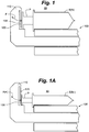
- System 10 includes a syringe pump 100 for a syringe S having a plunger P.
- Syringe S is of a size or diameter (N) (e.g., a 30 ml syringe) that contains a medication to be delivered to a patient from pump 100 acting on syringe S by way of a plunger driver 110.
- Driver 110 includes an integrally formed bendable element 120.
- a force sensor 130 is also integrally formed with driver 110.
- element 120 would be deflected (indicated by phantom line F(+)) with a greater moment arm and thus into more forceful contact with force sensor 130, compared to such contact from a relatively shorter moment arm shown in Figure 1 from the larger syringe size (N).
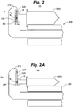
- System 20 includes a syringe pump 200 for a syringe S having a plunger P.
- Syringe S is of a size or diameter (N) (e.g., a 30 ml syringe) that contains a medication to be delivered to a patient from pump 200 acting on syringe S by way of a plunger driver 210.
- a pivotable element 220 is connected to driver 210 by a link 225 (e.g., a pin through a corresponding hole in element 220).
- a force sensor 230 is integrally formed with driver 210.
- element 220 would be deflected (indicated by phantom line F(+)) with a greater moment arm and thus into more forceful contact with force sensor 230, compared to such contact from a relatively shorter moment arm shown in Figure 2 from the larger syringe size (N).
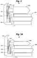
- System 30 includes a syringe pump 300 for a syringe S having a plunger P.
- Syringe S is of a size or diameter (N) (e.g., a 30 ml syringe) that contains a medication to be delivered to a patient from pump 300 acting on syringe S by way of a plunger driver 310.
- a pivotable sliding element 320 is connected to driver 310 by a link 325 (e.g., a pin in a spring-loaded slot 327 in element 320; details of the spring-loaded slot 327 have been omitted for clarity of the drawing).
- a force sensor 330 is integrally formed with driver 310. As shown in Figure 3 , upon occurrence of an occlusion plunger P would exert a force backwardly against pivotable sliding element 320, thereby deflecting element 320 about link 325 (indicated by phantom line F) into contact with force sensor 330 to thereby generate a signal indicating the occurrence of the occlusion.
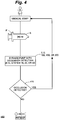
- FIG. 4 therein illustrated generally is an example of a method for occlusion detection 400 in, e.g., a clinical setting having medical staff M.
- medical staff M would load a syringe S of a size (N) containing a selected medication for a patient into a syringe pump (e.g., the aforementioned pumps 100, 200, or 300).
- syringe S would include a plunger P.
- the syringe pump would include a plunger driver such as, e.g., the aforementioned drivers 110, 210, and 310.
- An element e.g., the aforementioned bendable element 120, pivotable element 220, or pivotable sliding element 320
- a force sensor such as, e.g., the aforementioned sensors 130, 230, or 330, would be integrally formed with the plunger driver.
- the syringe pump would administer the medication to the patient (typically, e.g., through an intravenous line from the syringe to the patient).
- the plunger Upon occurrence of an occlusion, the plunger would exert a force backwardly against the element, thereby deflecting the element into contact with the force sensor.
- the force sensor would responsively generate a signal that would be sent to the medical staff alerting them to the occurrence of the occlusion as indicated by symbol 410 in the drawing.
- FIG. 1 Another embodiment of an example of a system for occlusion detection could utilize a substantially unitary, combination component of a bendable element with a force sensor.
- the force sensor would respond to a bending moment by being incorporated with or into the bendable element itself, instead of separate bendable element and force sensor components as shown in, e.g., the various examples of Figures 1 , 2 , and 3 .
- the force sensor could comprise a commercially available Honeywell 1865 Pressure Transducer.
- any suitable alternatives may be employed to provide novel and inventive systems for, and methods of, occlusion detection described by example or otherwise contemplated herein.
- the bendable elements, force sensors, and combination components collectively, regardless of particular constructions, "force components”
- this "integrally formed” terminology broadly includes constructions wherein (i) the force components are formed essentially as one with the plunger driver and also wherein (ii) the force components are physically separate from but attached to, connected to, or otherwise contained within, the plunger driver.
- compositions, sizes, and strengths of various aforementioned components of systems for, and methods of, occlusion detection described by example or otherwise contemplated herein are all a matter of design choice depending upon intended uses thereof.
Landscapes
- Health & Medical Sciences (AREA)
- Life Sciences & Earth Sciences (AREA)
- Engineering & Computer Science (AREA)
- Public Health (AREA)
- Biomedical Technology (AREA)
- Heart & Thoracic Surgery (AREA)
- Animal Behavior & Ethology (AREA)
- General Health & Medical Sciences (AREA)
- Veterinary Medicine (AREA)
- Hematology (AREA)
- Anesthesiology (AREA)
- Vascular Medicine (AREA)
- Chemical & Material Sciences (AREA)
- Bioinformatics & Cheminformatics (AREA)
- Medicinal Chemistry (AREA)
- Pharmacology & Pharmacy (AREA)
- Physics & Mathematics (AREA)
- Biophysics (AREA)
- Pathology (AREA)
- Medical Informatics (AREA)
- Molecular Biology (AREA)
- Surgery (AREA)
- Infusion, Injection, And Reservoir Apparatuses (AREA)
Claims (8)
- System zur Verstopfungserkennung, aufweisend:eine Spritzenpumpe (100, 200, 300) für eine Spritze (S), die ein Medikament enthält, wobei die Spritze (S) einen Kolben (P) aufweist und die Spritzenpumpe (100, 200, 300) einen Kolbenantrieb (110, 210, 310) aufweist;ein Element (120, 220, 320) innerhalb des Kolbenantriebs (110, 210, 310), wobei das Element ausgewählt ist aus einer Gruppe bestehend aus einem biegsamen Element (120) und einem schwenkbar gleitenden Element (320); undeinen Kraftaufnehmer (130, 230, 330), der einstückig mit dem Kolbenantrieb (110, 210, 310) ausgebildet ist, wobei bei Auftreten einer Verstopfung der Kolben eine rückwärts gerichtete Kraft gegen das Element (120, 220, 320) ausübt, wobei das Element (120, 220, 320) bis zum Kontakt mit dem Kraftaufnehmer (130, 230, 330) ausgelenkt wird, um dadurch ein Signal zu erzeugen, das das Auftreten der Verstopfung angibt.
- System zur Verstopfungserkennung nach Anspruch 1, wobei das Element (120, 220, 320) ein biegsames Element (120) ist und das biegsame Element (120) einstückig mit dem Kolbenantrieb (110, 210, 310) ausgebildet ist.
- System zur Verstopfungserkennung nach Anspruch 1, wobei das Element (120, 220, 320) ein schwenkbar gleitendes Element (320) ist, wobei das schwenkbar gleitende Element (320) einen federbelasteten Schlitz (327) aufweist, wobei das schwenkbar gleitende Element (320) durch ein innerhalb des federbelasteten Schlitzes (327) angeordnetes Gelenk (325) mit dem Kolbenantrieb (310) verbunden ist und das schwenkbar gleitende Element (320) um das Gelenk (325) in Kontakt mit dem Kraftaufnehmer (330) ausgelenkt wird.
- System zur Verstopfungserkennung nach einem der vorhergehenden Ansprüche, dadurch gekennzeichnet, dass Kräfte, die als Folge von Auftreten von Verstopfungen rückwärts gerichtet gegen das Element (120, 220, 320) ausgeübt werden, auf dem Kraftaufnehmer (130, 230, 330) wirken, an Größe zunehmen, wenn die Spritzengrößen aufgrund von entsprechend größeren Momentarmen auf dem Element (120, 220, 320) abnehmen.
- System zur Verstopfungserkennung nach Anspruch 1, wobei das Element (120, 220, 320) ein biegsames Element (120) ist und das biegsame Element (120) und der Kraftaufnehmer (130) in einer im Wesentlichen einheitlichen Kombinationskomponente kombiniert sind, die einstückig mit dem Kolbenantrieb (110) ausgebildet ist, wobei der Kolben (P) bei Auftreten einer Verstopfung eine rückwärts gerichtete Kraft gegen die Kombinationskomponente ausübt und dabei die Kombinationskomponente so auslenkt, dass ein Signal erzeugt wird, das das Auftreten der Verstopfung anzeigt.
- System zur Verstopfungserkennung nach Anspruch 5, wobei Kräfte, die als Folge von Auftreten von Verstopfungen rückwärts gerichtet gegen die Kombinationskomponente ausgeübt werden, auf die Kombinationskomponente wirken, an Größe zunehmen, wenn die Spritzengrößen aufgrund von entsprechend größeren Momentarmen auf der Kombinationskomponente abnehmen.
- Verfahren zur Verstopfungserkennung, umfassend:Bereitstellen einer Spritzenpumpe (100, 200, 300) für eine Spritze (S), die ein Medikament enthält, wobei die Spritze einen Kolben (P) aufweist und die Spritzenpumpe (100, 200, 300) (i) einen Kolbenantrieb (110, 210, 310) aufweist, (ii) ein Element (120, 220, 320) innerhalb des Kolbenantriebs (110, 210, 310) aufweist, wobei das Element (120, 220, 320) ausgewählt ist aus einer Gruppe bestehend aus einem biegsamen Element (120) und einem schwenkbar gleitenden Element (320), und (iii) einen Kraftaufnehmer (130, 230, 330) aufweist, der einstückig mit dem Kolbenantrieb (110, 210, 310) ausgebildet ist, wobei bei Auftreten einer Verstopfung der Kolben (P) eine rückwärts gerichtete Kraft gegen das Element (120, 220, 320) ausübt, wobei das Element (120, 220, 320) in Kontakt mit dem Kraftaufnehmer (130, 230, 330) ausgelenkt wird, um dadurch ein Signal zu erzeugen, das das Auftreten der Verstopfung angibt;Verabreichen des Medikaments an eine Infusionsleitung mithilfe der Spritzenpumpe (100, 200, 300); undSenden des vom Kraftaufnehmer (130, 230, 330) erzeugten Signals an medizinisches Personal nach Auftreten einer Verstopfung.
- Verfahren zur Verstopfungserkennung nach Anspruch 7, wobei das Element (120, 220, 320) ein biegsames Element (120) ist und das biegsame Element (120) und der Kraftaufnehmer (130) in einer im Wesentlichen einheitlichen Kombinationskomponente kombiniert sind, die einstückig mit dem Kolbenantrieb (110, 210, 310) ausgebildet ist, wobei der Kolben (P) bei Auftreten einer Verstopfung eine rückwärts gerichtete Kraft gegen die Kombinationskomponente ausübt und dabei die Kombinationskomponente so auslenkt, dass ein Signal erzeugt wird, das das Auftreten der Verstopfung anzeigt;
Verabreichen des Medikaments an eine Infusionsleitung mithilfe der Spritzenpumpe (100, 200, 300); und
Senden des von der Kombinationskomponente erzeugten Signals an medizinisches Personal nach Auftreten einer Verstopfung.
Applications Claiming Priority (2)
| Application Number | Priority Date | Filing Date | Title |
|---|---|---|---|
| US201261651860P | 2012-05-25 | 2012-05-25 | |
| PCT/US2013/042388 WO2013177379A1 (en) | 2012-05-25 | 2013-05-23 | Occlusion detection |
Publications (4)
| Publication Number | Publication Date |
|---|---|
| EP2854625A1 EP2854625A1 (de) | 2015-04-08 |
| EP2854625A4 EP2854625A4 (de) | 2015-11-18 |
| EP2854625B1 true EP2854625B1 (de) | 2017-10-04 |
| EP2854625B8 EP2854625B8 (de) | 2017-11-15 |
Family
ID=49624338
Family Applications (1)
| Application Number | Title | Priority Date | Filing Date |
|---|---|---|---|
| EP13794119.1A Not-in-force EP2854625B8 (de) | 2012-05-25 | 2013-05-23 | Verstopfungserkennung |
Country Status (10)
| Country | Link |
|---|---|
| US (2) | US10004847B2 (de) |
| EP (1) | EP2854625B8 (de) |
| JP (1) | JP2015517391A (de) |
| KR (1) | KR20150011841A (de) |
| CN (1) | CN104349712A (de) |
| AU (1) | AU2013266278B2 (de) |
| CA (1) | CA2872955A1 (de) |
| IN (1) | IN2014DN08873A (de) |
| SG (1) | SG11201407364QA (de) |
| WO (1) | WO2013177379A1 (de) |
Families Citing this family (21)
| Publication number | Priority date | Publication date | Assignee | Title |
|---|---|---|---|---|
| US9789247B2 (en) | 2011-12-21 | 2017-10-17 | Deka Products Limited Partnership | Syringe pump, and related method and system |
| US11217340B2 (en) | 2011-12-21 | 2022-01-04 | Deka Products Limited Partnership | Syringe pump having a pressure sensor assembly |
| US10293103B2 (en) | 2014-02-11 | 2019-05-21 | Smiths Medical Asd, Inc. | Pump startup algorithms and related systems and methods |
| EP3107601B1 (de) * | 2014-02-21 | 2020-12-23 | DEKA Products Limited Partnership | Spritzenpumpe mit einer drucksensoranordnung |
| CN106659846A (zh) | 2014-07-21 | 2017-05-10 | 施曼信医疗Asd公司 | 用于药剂注射器泵中的过载保护的方法和装置 |
| GB2529621B (en) * | 2014-08-21 | 2016-12-07 | Owen Mumford Ltd | Safety syringe |
| WO2016133635A1 (en) * | 2015-02-18 | 2016-08-25 | Smiths Medical Asd, Inc. | Occlusion sensor integrated within thixo magnesium plunger driver head |
| US10729848B2 (en) | 2015-06-17 | 2020-08-04 | Smiths Medical Asd, Inc. | Force sensing devices, systems and methods for syringe pumps |
| DE102016208622A1 (de) * | 2016-05-19 | 2017-11-23 | Robert Bosch Gmbh | Fluidabgabevorrichtung, Verfahren zum Herstellen und Verfahren zum Betreiben einer Fluidabgabevorrichtung zum Abgeben eines Fluids |
| JP7295840B2 (ja) | 2017-07-19 | 2023-06-21 | スミスズ メディカル エーエスディー,インコーポレイティド | 輸液ポンプのためのハウジング構造 |
| JP7471221B2 (ja) * | 2017-12-07 | 2024-04-19 | エフ・ホフマン-ラ・ロシュ・アクチェンゲゼルシャフト | 力試験機を検証するための検証装置、力試験機を検証する方法、及び力を測定する方法 |
| IL276561B2 (en) | 2018-02-11 | 2024-09-01 | Avoset Health Ltd | Flex-stroke infusion pump |
| JP2021522899A (ja) | 2018-05-03 | 2021-09-02 | スミスズ メディカル エーエスディー,インコーポレイティド | 注射器の取り扱いのためのシステム及び方法 |
| US11191897B2 (en) | 2019-03-04 | 2021-12-07 | Eitan Medical Ltd. | In cycle pressure measurement |
| WO2020178827A1 (en) | 2019-03-05 | 2020-09-10 | Avoset Health Ltd. | Anti-free-flow valve |
| US12186528B2 (en) | 2019-03-05 | 2025-01-07 | Eitan Medical Ltd. | Infusion pump cassette latch |
| US12318576B2 (en) | 2019-03-05 | 2025-06-03 | Eitan Medical Ltd. | Infusion pump with toggling capability |
| WO2020178824A1 (en) | 2019-03-05 | 2020-09-10 | Avoset Health Ltd. | Infusion pump with valve compensation |
| CN116568347A (zh) | 2020-12-09 | 2023-08-08 | 施曼信医疗Asd公司 | 具有阻塞检测的输注泵 |
| WO2024134532A1 (en) * | 2022-12-20 | 2024-06-27 | Karia Deval | System and method for delivery monitoring and occlusion detection in an infusion pump |
| WO2026039513A1 (en) * | 2024-08-14 | 2026-02-19 | Boston Scientific Scimed, Inc. | Medical systems and assemblies for delivering fluid |
Family Cites Families (38)
| Publication number | Priority date | Publication date | Assignee | Title |
|---|---|---|---|---|
| NL6904268A (de) | 1969-03-20 | 1970-09-22 | ||
| US4185759A (en) | 1978-02-17 | 1980-01-29 | Baxter Travenol Laboratories, Inc. | Fluid-flow limiting apparatus for use with intravenous-solution administering equipment |
| US4236880A (en) | 1979-03-09 | 1980-12-02 | Archibald Development Labs, Inc. | Nonpulsating IV pump and disposable pump chamber |
| US4336800A (en) | 1980-08-01 | 1982-06-29 | Oximetrix, Inc. | Intravenous metering device |
| JPS5997671A (ja) | 1982-11-26 | 1984-06-05 | テルモ株式会社 | シリンジ注入装置 |
| US4544369A (en) | 1983-11-22 | 1985-10-01 | C. R. Bard, Inc. | Battery operated miniature syringe infusion pump |
| US4762518A (en) | 1986-08-01 | 1988-08-09 | Pancretec, Inc. | Blockage hazard alarm in an intravenous system |
| US4804368A (en) | 1986-12-05 | 1989-02-14 | C. R. Bard, Inc. | Battery operated miniature syringe infusion pump and improved halfnut therefor |
| US4747828A (en) | 1986-12-09 | 1988-05-31 | Fisher Scientific Group | IV fluid line occlusion detector |
| JPH0423560Y2 (de) | 1987-02-17 | 1992-06-02 | ||
| EP0434672B1 (de) | 1987-06-19 | 1994-12-14 | The University Of Melbourne | Infusionspumpe |
| US4978335A (en) | 1989-09-29 | 1990-12-18 | Medex, Inc. | Infusion pump with bar code input to computer |
| WO1992022337A1 (en) | 1991-06-10 | 1992-12-23 | Baxter International Inc. | Intravenous metering monitoring device |
| US5232449A (en) | 1992-04-29 | 1993-08-03 | Becton, Dickinson And Company | Syringe pump pusher |
| CA2137772A1 (en) | 1992-06-09 | 1993-12-23 | Shan Padda | Programmable infusion pump with interchangeable tubing |
| US5295967A (en) * | 1992-09-23 | 1994-03-22 | Becton, Dickinson And Company | Syringe pump having continuous pressure monitoring and display |
| CA2125693C (en) | 1992-10-15 | 2005-05-03 | Alan D. Ford | An infusion pump with an electronically loadable drug library |
| FR2710537B1 (fr) | 1993-09-30 | 1995-12-01 | Becton Dickinson Co | Procédé et dispositif de détection d'occlusions dans une ligne de perfusion. |
| US5814015A (en) * | 1995-02-24 | 1998-09-29 | Harvard Clinical Technology, Inc. | Infusion pump for at least one syringe |
| US5647853A (en) * | 1995-03-03 | 1997-07-15 | Minimed Inc. | Rapid response occlusion detector for a medication infusion pump |
| US5989222A (en) | 1998-06-12 | 1999-11-23 | Abbott Laboratories | Pressure (occlusion) sensor |
| GB0020060D0 (en) * | 2000-08-16 | 2000-10-04 | Smiths Industries Plc | Syringe pumps |
| GB0020058D0 (en) | 2000-08-16 | 2000-10-04 | Smiths Industries Plc | Syringe pumps |
| US6572604B1 (en) | 2000-11-07 | 2003-06-03 | Baxter International Inc. | Occlusion detection method and system for ambulatory drug infusion pump |
| JP4261910B2 (ja) | 2001-02-22 | 2009-05-13 | テルモ株式会社 | シリンジポンプ |
| US7150724B2 (en) * | 2002-06-05 | 2006-12-19 | Cardinal Health 303, Inc. | Syringe plunger driver system |
| US7018361B2 (en) | 2002-06-14 | 2006-03-28 | Baxter International Inc. | Infusion pump |
| US8182461B2 (en) | 2003-11-04 | 2012-05-22 | Smiths Medical Asd, Inc. | Syringe pump rapid occlusion detection system |
| ITMO20040086A1 (it) | 2004-04-20 | 2004-07-20 | Gambro Lundia Ab | Metodo per controllare un dispositivo di infusione. |
| WO2006051539A2 (en) | 2004-11-12 | 2006-05-18 | Shaul Ozeri | A miniature infusion pump for a controlled delivery of medication |
| EP1818664B1 (de) | 2006-02-13 | 2013-05-01 | F.Hoffmann-La Roche Ag | Vorrichtung zur Erkennung einer Druckänderung im Flüssigkeitspfad einer Mikrodosiervorrichtung |
| JP2008264140A (ja) * | 2007-04-19 | 2008-11-06 | Japan Servo Co Ltd | 輸液装置における閉塞圧検知機構 |
| CN101970031B (zh) | 2008-03-14 | 2013-01-09 | 泰尔茂株式会社 | 注射器泵及其控制方法 |
| US8378837B2 (en) | 2009-02-20 | 2013-02-19 | Hospira, Inc. | Occlusion detection system |
| US8608699B2 (en) | 2009-03-31 | 2013-12-17 | Tandem Diabetes Care, Inc. | Systems and methods to address air, leaks and occlusions in an insulin pump system |
| CH701492A1 (de) | 2009-07-20 | 2011-01-31 | Tecpharma Licensing Ag | Verabreichungsvorrichtung mit einer Einrichtung zur Erfassung von Druckänderungen. |
| CN102114282A (zh) | 2009-12-31 | 2011-07-06 | 北京谊安医疗系统股份有限公司 | 注射器阻塞的检测机构 |
| US8937553B2 (en) | 2010-01-29 | 2015-01-20 | Panasonic Corporation | Syringe drive device and syringe drive method |
-
2013
- 2013-05-23 EP EP13794119.1A patent/EP2854625B8/de not_active Not-in-force
- 2013-05-23 SG SG11201407364QA patent/SG11201407364QA/en unknown
- 2013-05-23 CN CN201380027501.2A patent/CN104349712A/zh active Pending
- 2013-05-23 KR KR1020147035934A patent/KR20150011841A/ko not_active Withdrawn
- 2013-05-23 US US14/400,509 patent/US10004847B2/en not_active Expired - Fee Related
- 2013-05-23 IN IN8873DEN2014 patent/IN2014DN08873A/en unknown
- 2013-05-23 AU AU2013266278A patent/AU2013266278B2/en not_active Ceased
- 2013-05-23 CA CA2872955A patent/CA2872955A1/en not_active Abandoned
- 2013-05-23 WO PCT/US2013/042388 patent/WO2013177379A1/en not_active Ceased
- 2013-05-23 JP JP2015514175A patent/JP2015517391A/ja active Pending
-
2018
- 2018-02-06 US US15/889,912 patent/US20180169329A1/en not_active Abandoned
Also Published As
| Publication number | Publication date |
|---|---|
| CA2872955A1 (en) | 2013-11-28 |
| AU2013266278A1 (en) | 2014-11-06 |
| US10004847B2 (en) | 2018-06-26 |
| SG11201407364QA (en) | 2014-12-30 |
| EP2854625A1 (de) | 2015-04-08 |
| EP2854625A4 (de) | 2015-11-18 |
| US20180169329A1 (en) | 2018-06-21 |
| WO2013177379A1 (en) | 2013-11-28 |
| EP2854625B8 (de) | 2017-11-15 |
| KR20150011841A (ko) | 2015-02-02 |
| CN104349712A (zh) | 2015-02-11 |
| US20150133890A1 (en) | 2015-05-14 |
| JP2015517391A (ja) | 2015-06-22 |
| AU2013266278B2 (en) | 2017-10-12 |
| IN2014DN08873A (de) | 2015-05-22 |
Similar Documents
| Publication | Publication Date | Title |
|---|---|---|
| US10004847B2 (en) | Occlusion detection | |
| US20230030641A1 (en) | Methods and systems for detecting infusion pump conditions | |
| JP6525879B2 (ja) | パルス式圧力信号を用いて薬剤注入システム内の閉塞を検出するためのシステムおよび方法 | |
| US6572604B1 (en) | Occlusion detection method and system for ambulatory drug infusion pump | |
| EP3341046B1 (de) | Infusionsvorrichtung zur verabreichung eines medizinischen fluids an einen patienten | |
| AU2010215973A1 (en) | Occlusion detection system | |
| US20240197988A1 (en) | Systems and methods for improving operation of infusion pumps | |
| US9611058B2 (en) | Filling device and controller for filling an administration container | |
| WO2016133635A1 (en) | Occlusion sensor integrated within thixo magnesium plunger driver head | |
| CN110022915B (zh) | 构造成检测推注注射期间的异常情况的输注装置 | |
| EP4630078A1 (de) | Dedizierte verbrauchsartikelsets mit durchflussratensensoren |
Legal Events
| Date | Code | Title | Description |
|---|---|---|---|
| PUAI | Public reference made under article 153(3) epc to a published international application that has entered the european phase |
Free format text: ORIGINAL CODE: 0009012 |
|
| 17P | Request for examination filed |
Effective date: 20141030 |
|
| AK | Designated contracting states |
Kind code of ref document: A1 Designated state(s): AL AT BE BG CH CY CZ DE DK EE ES FI FR GB GR HR HU IE IS IT LI LT LU LV MC MK MT NL NO PL PT RO RS SE SI SK SM TR |
|
| AX | Request for extension of the european patent |
Extension state: BA ME |
|
| DAX | Request for extension of the european patent (deleted) | ||
| RA4 | Supplementary search report drawn up and despatched (corrected) |
Effective date: 20151020 |
|
| RIC1 | Information provided on ipc code assigned before grant |
Ipc: A61M 5/168 20060101ALI20151014BHEP Ipc: A61M 5/142 20060101ALI20151014BHEP Ipc: A61M 5/145 20060101ALN20151014BHEP Ipc: A61B 5/02 20060101AFI20151014BHEP Ipc: A61B 5/00 20060101ALN20151014BHEP |
|
| GRAP | Despatch of communication of intention to grant a patent |
Free format text: ORIGINAL CODE: EPIDOSNIGR1 |
|
| RIC1 | Information provided on ipc code assigned before grant |
Ipc: A61M 5/142 20060101ALI20161031BHEP Ipc: A61M 5/145 20060101ALN20161031BHEP Ipc: A61B 5/02 20060101AFI20161031BHEP Ipc: A61B 5/00 20060101ALN20161031BHEP Ipc: A61M 5/168 20060101ALI20161031BHEP |
|
| INTG | Intention to grant announced |
Effective date: 20161124 |
|
| GRAJ | Information related to disapproval of communication of intention to grant by the applicant or resumption of examination proceedings by the epo deleted |
Free format text: ORIGINAL CODE: EPIDOSDIGR1 |
|
| GRAP | Despatch of communication of intention to grant a patent |
Free format text: ORIGINAL CODE: EPIDOSNIGR1 |
|
| INTC | Intention to grant announced (deleted) | ||
| RIC1 | Information provided on ipc code assigned before grant |
Ipc: A61M 5/145 20060101ALN20170404BHEP Ipc: A61M 5/168 20060101ALI20170404BHEP Ipc: A61B 5/00 20060101ALN20170404BHEP Ipc: A61M 5/142 20060101ALI20170404BHEP Ipc: A61B 5/02 20060101AFI20170404BHEP |
|
| INTG | Intention to grant announced |
Effective date: 20170420 |
|
| GRAS | Grant fee paid |
Free format text: ORIGINAL CODE: EPIDOSNIGR3 |
|
| GRAA | (expected) grant |
Free format text: ORIGINAL CODE: 0009210 |
|
| AK | Designated contracting states |
Kind code of ref document: B1 Designated state(s): AL AT BE BG CH CY CZ DE DK EE ES FI FR GB GR HR HU IE IS IT LI LT LU LV MC MK MT NL NO PL PT RO RS SE SI SK SM TR |
|
| REG | Reference to a national code |
Ref country code: GB Ref legal event code: FG4D |
|
| REG | Reference to a national code |
Ref country code: CH Ref legal event code: EP |
|
| REG | Reference to a national code |
Ref country code: AT Ref legal event code: REF Ref document number: 933233 Country of ref document: AT Kind code of ref document: T Effective date: 20171015 |
|
| REG | Reference to a national code |
Ref country code: DE Ref legal event code: R082 Ref document number: 602013027566 Country of ref document: DE Representative=s name: NOVAGRAAF BREVETS, FR |
|
| RAP2 | Party data changed (patent owner data changed or rights of a patent transferred) |
Owner name: SMITHS MEDICAL ASD, INC. |
|
| REG | Reference to a national code |
Ref country code: IE Ref legal event code: FG4D |
|
| RIN2 | Information on inventor provided after grant (corrected) |
Inventor name: WANDER, JACOB, A. Inventor name: LACY, CHRISTOPHER, A. Inventor name: ADAMS, GRANT, A. |
|
| REG | Reference to a national code |
Ref country code: DE Ref legal event code: R096 Ref document number: 602013027566 Country of ref document: DE |
|
| REG | Reference to a national code |
Ref country code: NL Ref legal event code: MP Effective date: 20171004 |
|
| REG | Reference to a national code |
Ref country code: LT Ref legal event code: MG4D |
|
| REG | Reference to a national code |
Ref country code: AT Ref legal event code: MK05 Ref document number: 933233 Country of ref document: AT Kind code of ref document: T Effective date: 20171004 |
|
| PG25 | Lapsed in a contracting state [announced via postgrant information from national office to epo] |
Ref country code: NL Free format text: LAPSE BECAUSE OF FAILURE TO SUBMIT A TRANSLATION OF THE DESCRIPTION OR TO PAY THE FEE WITHIN THE PRESCRIBED TIME-LIMIT Effective date: 20171004 |
|
| REG | Reference to a national code |
Ref country code: FR Ref legal event code: PLFP Year of fee payment: 6 |
|
| PG25 | Lapsed in a contracting state [announced via postgrant information from national office to epo] |
Ref country code: FI Free format text: LAPSE BECAUSE OF FAILURE TO SUBMIT A TRANSLATION OF THE DESCRIPTION OR TO PAY THE FEE WITHIN THE PRESCRIBED TIME-LIMIT Effective date: 20171004 Ref country code: SE Free format text: LAPSE BECAUSE OF FAILURE TO SUBMIT A TRANSLATION OF THE DESCRIPTION OR TO PAY THE FEE WITHIN THE PRESCRIBED TIME-LIMIT Effective date: 20171004 Ref country code: LT Free format text: LAPSE BECAUSE OF FAILURE TO SUBMIT A TRANSLATION OF THE DESCRIPTION OR TO PAY THE FEE WITHIN THE PRESCRIBED TIME-LIMIT Effective date: 20171004 Ref country code: ES Free format text: LAPSE BECAUSE OF FAILURE TO SUBMIT A TRANSLATION OF THE DESCRIPTION OR TO PAY THE FEE WITHIN THE PRESCRIBED TIME-LIMIT Effective date: 20171004 Ref country code: NO Free format text: LAPSE BECAUSE OF FAILURE TO SUBMIT A TRANSLATION OF THE DESCRIPTION OR TO PAY THE FEE WITHIN THE PRESCRIBED TIME-LIMIT Effective date: 20180104 |
|
| PG25 | Lapsed in a contracting state [announced via postgrant information from national office to epo] |
Ref country code: LV Free format text: LAPSE BECAUSE OF FAILURE TO SUBMIT A TRANSLATION OF THE DESCRIPTION OR TO PAY THE FEE WITHIN THE PRESCRIBED TIME-LIMIT Effective date: 20171004 Ref country code: BG Free format text: LAPSE BECAUSE OF FAILURE TO SUBMIT A TRANSLATION OF THE DESCRIPTION OR TO PAY THE FEE WITHIN THE PRESCRIBED TIME-LIMIT Effective date: 20180104 Ref country code: RS Free format text: LAPSE BECAUSE OF FAILURE TO SUBMIT A TRANSLATION OF THE DESCRIPTION OR TO PAY THE FEE WITHIN THE PRESCRIBED TIME-LIMIT Effective date: 20171004 Ref country code: HR Free format text: LAPSE BECAUSE OF FAILURE TO SUBMIT A TRANSLATION OF THE DESCRIPTION OR TO PAY THE FEE WITHIN THE PRESCRIBED TIME-LIMIT Effective date: 20171004 Ref country code: GR Free format text: LAPSE BECAUSE OF FAILURE TO SUBMIT A TRANSLATION OF THE DESCRIPTION OR TO PAY THE FEE WITHIN THE PRESCRIBED TIME-LIMIT Effective date: 20180105 Ref country code: IS Free format text: LAPSE BECAUSE OF FAILURE TO SUBMIT A TRANSLATION OF THE DESCRIPTION OR TO PAY THE FEE WITHIN THE PRESCRIBED TIME-LIMIT Effective date: 20180204 Ref country code: AT Free format text: LAPSE BECAUSE OF FAILURE TO SUBMIT A TRANSLATION OF THE DESCRIPTION OR TO PAY THE FEE WITHIN THE PRESCRIBED TIME-LIMIT Effective date: 20171004 |
|
| REG | Reference to a national code |
Ref country code: DE Ref legal event code: R097 Ref document number: 602013027566 Country of ref document: DE |
|
| PG25 | Lapsed in a contracting state [announced via postgrant information from national office to epo] |
Ref country code: SK Free format text: LAPSE BECAUSE OF FAILURE TO SUBMIT A TRANSLATION OF THE DESCRIPTION OR TO PAY THE FEE WITHIN THE PRESCRIBED TIME-LIMIT Effective date: 20171004 Ref country code: CZ Free format text: LAPSE BECAUSE OF FAILURE TO SUBMIT A TRANSLATION OF THE DESCRIPTION OR TO PAY THE FEE WITHIN THE PRESCRIBED TIME-LIMIT Effective date: 20171004 Ref country code: DK Free format text: LAPSE BECAUSE OF FAILURE TO SUBMIT A TRANSLATION OF THE DESCRIPTION OR TO PAY THE FEE WITHIN THE PRESCRIBED TIME-LIMIT Effective date: 20171004 Ref country code: EE Free format text: LAPSE BECAUSE OF FAILURE TO SUBMIT A TRANSLATION OF THE DESCRIPTION OR TO PAY THE FEE WITHIN THE PRESCRIBED TIME-LIMIT Effective date: 20171004 |
|
| PLBE | No opposition filed within time limit |
Free format text: ORIGINAL CODE: 0009261 |
|
| STAA | Information on the status of an ep patent application or granted ep patent |
Free format text: STATUS: NO OPPOSITION FILED WITHIN TIME LIMIT |
|
| PG25 | Lapsed in a contracting state [announced via postgrant information from national office to epo] |
Ref country code: PL Free format text: LAPSE BECAUSE OF FAILURE TO SUBMIT A TRANSLATION OF THE DESCRIPTION OR TO PAY THE FEE WITHIN THE PRESCRIBED TIME-LIMIT Effective date: 20171004 Ref country code: RO Free format text: LAPSE BECAUSE OF FAILURE TO SUBMIT A TRANSLATION OF THE DESCRIPTION OR TO PAY THE FEE WITHIN THE PRESCRIBED TIME-LIMIT Effective date: 20171004 Ref country code: SM Free format text: LAPSE BECAUSE OF FAILURE TO SUBMIT A TRANSLATION OF THE DESCRIPTION OR TO PAY THE FEE WITHIN THE PRESCRIBED TIME-LIMIT Effective date: 20171004 |
|
| PGFP | Annual fee paid to national office [announced via postgrant information from national office to epo] |
Ref country code: IT Payment date: 20180522 Year of fee payment: 6 |
|
| 26N | No opposition filed |
Effective date: 20180705 |
|
| PG25 | Lapsed in a contracting state [announced via postgrant information from national office to epo] |
Ref country code: SI Free format text: LAPSE BECAUSE OF FAILURE TO SUBMIT A TRANSLATION OF THE DESCRIPTION OR TO PAY THE FEE WITHIN THE PRESCRIBED TIME-LIMIT Effective date: 20171004 |
|
| REG | Reference to a national code |
Ref country code: CH Ref legal event code: PL |
|
| REG | Reference to a national code |
Ref country code: BE Ref legal event code: MM Effective date: 20180531 |
|
| PG25 | Lapsed in a contracting state [announced via postgrant information from national office to epo] |
Ref country code: MC Free format text: LAPSE BECAUSE OF FAILURE TO SUBMIT A TRANSLATION OF THE DESCRIPTION OR TO PAY THE FEE WITHIN THE PRESCRIBED TIME-LIMIT Effective date: 20171004 |
|
| REG | Reference to a national code |
Ref country code: IE Ref legal event code: MM4A |
|
| PG25 | Lapsed in a contracting state [announced via postgrant information from national office to epo] |
Ref country code: CH Free format text: LAPSE BECAUSE OF NON-PAYMENT OF DUE FEES Effective date: 20180531 Ref country code: LI Free format text: LAPSE BECAUSE OF NON-PAYMENT OF DUE FEES Effective date: 20180531 |
|
| PG25 | Lapsed in a contracting state [announced via postgrant information from national office to epo] |
Ref country code: LU Free format text: LAPSE BECAUSE OF NON-PAYMENT OF DUE FEES Effective date: 20180523 |
|
| PG25 | Lapsed in a contracting state [announced via postgrant information from national office to epo] |
Ref country code: IE Free format text: LAPSE BECAUSE OF NON-PAYMENT OF DUE FEES Effective date: 20180523 |
|
| PG25 | Lapsed in a contracting state [announced via postgrant information from national office to epo] |
Ref country code: BE Free format text: LAPSE BECAUSE OF NON-PAYMENT OF DUE FEES Effective date: 20180531 |
|
| PG25 | Lapsed in a contracting state [announced via postgrant information from national office to epo] |
Ref country code: MT Free format text: LAPSE BECAUSE OF NON-PAYMENT OF DUE FEES Effective date: 20180523 |
|
| PG25 | Lapsed in a contracting state [announced via postgrant information from national office to epo] |
Ref country code: TR Free format text: LAPSE BECAUSE OF FAILURE TO SUBMIT A TRANSLATION OF THE DESCRIPTION OR TO PAY THE FEE WITHIN THE PRESCRIBED TIME-LIMIT Effective date: 20171004 |
|
| PG25 | Lapsed in a contracting state [announced via postgrant information from national office to epo] |
Ref country code: IT Free format text: LAPSE BECAUSE OF NON-PAYMENT OF DUE FEES Effective date: 20190523 |
|
| PG25 | Lapsed in a contracting state [announced via postgrant information from national office to epo] |
Ref country code: PT Free format text: LAPSE BECAUSE OF FAILURE TO SUBMIT A TRANSLATION OF THE DESCRIPTION OR TO PAY THE FEE WITHIN THE PRESCRIBED TIME-LIMIT Effective date: 20171004 Ref country code: HU Free format text: LAPSE BECAUSE OF FAILURE TO SUBMIT A TRANSLATION OF THE DESCRIPTION OR TO PAY THE FEE WITHIN THE PRESCRIBED TIME-LIMIT; INVALID AB INITIO Effective date: 20130523 |
|
| PG25 | Lapsed in a contracting state [announced via postgrant information from national office to epo] |
Ref country code: CY Free format text: LAPSE BECAUSE OF FAILURE TO SUBMIT A TRANSLATION OF THE DESCRIPTION OR TO PAY THE FEE WITHIN THE PRESCRIBED TIME-LIMIT Effective date: 20171004 Ref country code: MK Free format text: LAPSE BECAUSE OF NON-PAYMENT OF DUE FEES Effective date: 20171004 |
|
| PG25 | Lapsed in a contracting state [announced via postgrant information from national office to epo] |
Ref country code: AL Free format text: LAPSE BECAUSE OF FAILURE TO SUBMIT A TRANSLATION OF THE DESCRIPTION OR TO PAY THE FEE WITHIN THE PRESCRIBED TIME-LIMIT Effective date: 20171004 |
|
| PGFP | Annual fee paid to national office [announced via postgrant information from national office to epo] |
Ref country code: FR Payment date: 20200414 Year of fee payment: 8 Ref country code: DE Payment date: 20200512 Year of fee payment: 8 |
|
| PGFP | Annual fee paid to national office [announced via postgrant information from national office to epo] |
Ref country code: GB Payment date: 20200513 Year of fee payment: 8 |
|
| REG | Reference to a national code |
Ref country code: DE Ref legal event code: R119 Ref document number: 602013027566 Country of ref document: DE |
|
| GBPC | Gb: european patent ceased through non-payment of renewal fee |
Effective date: 20210523 |
|
| PG25 | Lapsed in a contracting state [announced via postgrant information from national office to epo] |
Ref country code: GB Free format text: LAPSE BECAUSE OF NON-PAYMENT OF DUE FEES Effective date: 20210523 Ref country code: DE Free format text: LAPSE BECAUSE OF NON-PAYMENT OF DUE FEES Effective date: 20211201 |
|
| PG25 | Lapsed in a contracting state [announced via postgrant information from national office to epo] |
Ref country code: FR Free format text: LAPSE BECAUSE OF NON-PAYMENT OF DUE FEES Effective date: 20210531 |