EP2855800B1 - Riegel mit wellenstruktur - Google Patents
Riegel mit wellenstruktur Download PDFInfo
- Publication number
- EP2855800B1 EP2855800B1 EP13726195.4A EP13726195A EP2855800B1 EP 2855800 B1 EP2855800 B1 EP 2855800B1 EP 13726195 A EP13726195 A EP 13726195A EP 2855800 B1 EP2855800 B1 EP 2855800B1
- Authority
- EP
- European Patent Office
- Prior art keywords
- bolt
- latch
- lock
- cross
- surface profile
- Prior art date
- Legal status (The legal status is an assumption and is not a legal conclusion. Google has not performed a legal analysis and makes no representation as to the accuracy of the status listed.)
- Not-in-force
Links
Images

Classifications
-
- E—FIXED CONSTRUCTIONS
- E05—LOCKS; KEYS; WINDOW OR DOOR FITTINGS; SAFES
- E05B—LOCKS; ACCESSORIES THEREFOR; HANDCUFFS
- E05B17/00—Accessories in connection with locks
- E05B17/20—Means independent of the locking mechanism for preventing unauthorised opening, e.g. for securing the bolt in the fastening position
- E05B17/2003—Preventing opening by insertion of a tool, e.g. flexible, between door and jamb to withdraw the bolt
-
- E—FIXED CONSTRUCTIONS
- E05—LOCKS; KEYS; WINDOW OR DOOR FITTINGS; SAFES
- E05C—BOLTS OR FASTENING DEVICES FOR WINGS, SPECIALLY FOR DOORS OR WINDOWS
- E05C1/00—Fastening devices with bolts moving rectilinearly
- E05C1/08—Fastening devices with bolts moving rectilinearly with latching action
-
- E—FIXED CONSTRUCTIONS
- E05—LOCKS; KEYS; WINDOW OR DOOR FITTINGS; SAFES
- E05B—LOCKS; ACCESSORIES THEREFOR; HANDCUFFS
- E05B15/00—Other details of locks; Parts for engagement by bolts of fastening devices
- E05B15/10—Bolts of locks or night latches
-
- E—FIXED CONSTRUCTIONS
- E05—LOCKS; KEYS; WINDOW OR DOOR FITTINGS; SAFES
- E05B—LOCKS; ACCESSORIES THEREFOR; HANDCUFFS
- E05B15/00—Other details of locks; Parts for engagement by bolts of fastening devices
- E05B15/10—Bolts of locks or night latches
- E05B15/101—Spring-retracted bolts
-
- E—FIXED CONSTRUCTIONS
- E05—LOCKS; KEYS; WINDOW OR DOOR FITTINGS; SAFES
- E05B—LOCKS; ACCESSORIES THEREFOR; HANDCUFFS
- E05B9/00—Lock casings or latch-mechanism casings ; Fastening locks or fasteners or parts thereof to the wing
- E05B9/02—Casings of latch-bolt or deadbolt locks
-
- Y—GENERAL TAGGING OF NEW TECHNOLOGICAL DEVELOPMENTS; GENERAL TAGGING OF CROSS-SECTIONAL TECHNOLOGIES SPANNING OVER SEVERAL SECTIONS OF THE IPC; TECHNICAL SUBJECTS COVERED BY FORMER USPC CROSS-REFERENCE ART COLLECTIONS [XRACs] AND DIGESTS
- Y10—TECHNICAL SUBJECTS COVERED BY FORMER USPC
- Y10T—TECHNICAL SUBJECTS COVERED BY FORMER US CLASSIFICATION
- Y10T292/00—Closure fasteners
- Y10T292/08—Bolts
- Y10T292/096—Sliding
- Y10T292/0969—Spring projected
- Y10T292/097—Operating means
Definitions
- the invention relates to a lock for a door, window or the like.
- the invention is based on a prior art in which locks with a lock case and a stored in the lock case lock mechanism are known, the lock mechanism is actuated via a manual and / or motorized actuator.
- the lock mechanism has a retractable and retractable latch and / or a spring-mounted retractable and retractable latch.
- the bolt is generally formed as a cuboid body, and the lock latch is formed at its free end with an inclined surface as an inlet slope.
- the locks are more or less contrary to burglary attempts. By introducing flat burglary tools, however, it is possible to intervene in the lock mechanism in order to manipulate or damage it.
- the locking element is movably mounted in a lock case.
- the lock case is provided with an opening through which the locking element can pass.
- the cross-section of the bars in the plane perpendicular to the direction of movement thereof has a surface profile which is formed with elevations and depressions.
- the opening associated with the locking element has an opening edge, which is formed with only a slight clearance complementary to the contour of the surface profile of the locking element.
- the invention has for its object to provide a lock in which the introduction of burglary tools in the lock case over the above-mentioned prior art is made even more difficult.
- the body of the bolt or the lock latch has the shape of a body formed of a plurality of elongated rods, which are arranged transversely to their longitudinal extent side by side and thereby longitudinally adjacent to each other are integrally connected to each other, wherein the elongated rods of the body in cross section are round or oval.
- the lock has a lock case and a lock mechanism mounted in the lock case, which can be actuated via a manual and / or motorized actuation device.
- the lock mechanism has a retractable and extendable mounted latch and / or a spring-mounted retractable and extendable latch.
- In the cuff-side region of the lock case there is provided an opening associated with the lock or an opening associated with the lock catch, through which the lock or the lock catch engages in at least one locking position.
- the lock case can be completed on the cuff side by a separate sheet - a so-called cuff plate.
- the cuff plate has the bolt or the latch associated with the opening and can form the stulp preparede wall of the lock box.
- the body of the bolt and / or the body of the lock latch has at least one outer surface which extends along the direction of movement of the retraction and extension movement and which has a constant surface profile along this extension direction at least in the locking portion ,
- the term "body" of the bolt or the latch case is understood to mean the main body of the bolt or latch, which passes through the stülp knowledgeablee opening of the lock case during retraction and extension in the extended locking position of the bolt or the latch with a Lock associated strike plate cooperates, ie in this engages or otherwise cooperates with it under locking.
- the body is coupled at its lock-side end with a gear mechanism of the lock mechanism. He may have corresponding connection elements for this purpose.
- the body of the bolt may be formed integrally or also in several pieces.
- the invention provides that the latch and / or the latch is associated with an opening in the cuff-side area of the lock case, preferably in the cuff, through which the bolt or the Lock latch is retractable and retractable, wherein the opening has an opening edge which is formed complementary to the contour of the surface profile of the at least one uneven outer surface of the body.
- the opening cross-section of this gap is advantageously formed with only a small constant width. A flat, flat burglary tool can not be easily inserted.
- the bolt may be provided a plurality of locking positions of the bolt, which differ in that the bolt is extended to different degrees. In the locking position, it is important for the burglary protection that the gap to the opening edge of the face-side opening is small, and the contour of the opening edge is adapted to the uneven surface profile.
- the outer surface of the body of the bolt must for this purpose at least in the respective locking portion, d. H. the portion that forms the gap in the locking position with the opening edge, be formed with the uneven surface profile.
- Preferred embodiments can be embodied such that the entire outer surface of the locking body, which extends along the direction of movement of the retraction and extension movement, along this direction of extension has a constant uneven surface profile.
- the latch may also have one or more locking positions, which differ in that the latch is extended in different positions in these positions. Especially in so-called. Self-locking latch traps two extended positions of the latch are provided.
- embodiments of the bolt and the lock latch which have a plurality of locking sections along their direction of movement.
- the number of locking sections corresponds to the number of Locking positions of the bolt and the latch.
- Between the locking portions of the bolt or the latch can be formed constricted arbitrarily with other cross-section.
- the uneven surface profile of the at least one outer surface extends continuously over the entire extent of the outer surface in the direction of movement of the retraction and extension movement.
- the body of the bolt or latch at some of its outer surfaces, extending in the direction of movement during extension and retraction, uneven, preferably on all outer surfaces which extend in this direction.
- Particularly preferred embodiments are those in which the surface profile has a wave structure, wherein the waves extend along the direction of movement of the retraction and extension movement.
- the waves may each be formed differently in the respective structure, in particular adjacent waves may be formed differently.
- the waves of the wave structure are each formed identically. If the waves are designed differently, periodic designs are particularly preferred.
- the body of the bolt or the lock latch is substantially formed as a cuboid, which has a cross-section transverse to the direction of movement of the retraction and extension, which is constant over the entire extent of the body in this direction, and that all in the direction of movement of the retraction and extension movement extending outer surfaces are formed with uneven surface profile.
- the uneven structure of the surface of the extending in the extension and retraction surface structure may be the same at the different longitudinal outer sides of the cuboid, or at least on the opposite outer surfaces in pairs.
- the preferably resiliently supported latch can be formed with outer surfaces with uneven surface structure, and that at least in the locking portions, the surfaces extending in the extension and retraction.
- the latch preferably has a bevel, which is formed as an inlet slope. This slope is preferably designed as a flat surface.
- the body of the bolt or the latch is substantially formed as a cuboid with an end portion as a triangular prism in cross section and at least one outer surface which is formed as a flat inclined surface as an inlet slope, wherein at least one of the remaining External surfaces of the body, moving in the direction of movement of the inlet and Extending extend, is designed as an outer surface with uneven surface profile.
- two opposite outer surfaces of the body, which are connected to one another via the slope are formed as outer surfaces with an uneven surface profile.
- the body of the bolt or the lock latch has the shape of a body which is formed of a plurality of elongated rods which are arranged transversely to their longitudinal extent side by side and thereby longitudinally adjacent to each other along the longitudinal side in one piece with each other are connected.
- the elongated rods are formed differently in their cross-sectional shape and / or in their cross-sectional size.
- Embodiments are advantageous in which the cross-sectional shape of the elongated and / or the cross-sectional size of the elongated rods are identical.
- the bolt and / or the latch may also be self-locking versions, preferably to versions with unlocking pin.
- the unlocking pin extends in preferred embodiments axially in a central axis of the bolt or the lock latch, but can also run eccentrically and externally on the bolt or the lock latch.
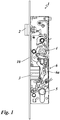
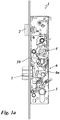
- the embodiment shown in the figures is in each case a lock.
- the lock on a lock case 1 a lock mechanism is mounted.
- the lock mechanism comprises a spring-mounted latch 2 and a bolt 3 and a nut 4 for connecting an actuating device, not shown.
- the actuator can be used as a manual handle, z. B. be designed as a pusher; but it can also be designed as a motorized actuator.
- the lock further has a lock cylinder 5 and a switching device 6 in the lock case 1.
- the lock cylinder 5 is actuated by a key and thereby controls the switching device 6.
- the switching device 6 has an actuating arm 6a, which cooperates with its one end with the lock cylinder 5 and with its other end with the bolt 3. By operating the lock cylinder 5 via the key, the actuating arm 6a of the switching device 6 is displaced and thereby the bolt 3 is controlled.
- the bolt 3 is formed in the illustrated embodiment as a substantially cuboidal body. It is mounted linearly displaceable in the lock housing 1, and along its longitudinal extent. In the sliding movement of the bolt 3 passes through the free end of his body an opening 10a in the cuff-side housing wall of the lock case 1.
- the cuff-side housing wall is formed in the illustrated case by a cuff plate 10.
- the opening 10a in the cuff plate 10 has an opening cross-section which is complementary to the cross-section of the bolt 3, in such a way that the bolt 3 is guided with little play in the edge of the opening 10 a. It is essential that the body of the bolt 3 at its longitudinally extending outer surfaces has uneven profiled surfaces. The two opposite large longitudinal side surfaces of the body have a wave structure.
- the two opposite end-side longitudinal surfaces are convexly curved, in the illustrated case, forming a single wave crest.
- the body has transversely to its longitudinal extent therewith a cross-section which consists of five substantially circular sections which are arranged in a row next to one another, wherein adjacent circular sections in the row adjoin one another and are connected to one another in a transitional manner.
- the body thus has the shape of a body, which is formed of a plurality of circular cross-section rods, wherein the rods are adjacent to each other in a row, while adjacent the respective adjacent bars on its longitudinal side and merge integrally connected in this area into each other.
- the outer surfaces extending in the longitudinal direction of the body thus have an uneven surface profile.
- the gap to the complementary opening edge of the extension opening in the lock case 1 and forend 10 thus receives a contour of the surface profile corresponding gap cross-section. This will give a burglary protection.
- the introduction of a burglary tool is significantly hindered, because flat tool can not be inserted into the gap.
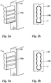
- FIGS. 2a and 2b show for the first embodiment, the cuff-side region of the lock case 1 with the latch 3 according to a first embodiment.
- the latch 3 is here in its extended position, ie the locking position shown.
- the body of the bolt 3 is substantially formed as a cuboid, wherein three of the outer surfaces have an uneven surface profile. In this embodiment, only the outer surface of the bolt 3 pointing downwards in the figures has a planar surface profile. It can be seen that the opening edge of the opening 10a in the cowl-side housing wall is designed to be complementary to the surface profile of the bolt 3.
- FIGS. 3a and 3b the further embodiment of the bolt 3 is shown.
- all four outer surfaces of the cuboid bar body are provided with an uneven surface profile.
- Fig. 3b shows a front view of the cuff-side region of the bolt 3 from Fig. 3a in the extended locking position.
- the opening edge of the opening 10a in the cuff-side housing wall is formed complementary to the surface profile of the bolt 3.
- FIG. 4 a further embodiment of the castle is shown.
- the lock shown comprises a latch 2 with a substantially cross-shaped chamfer 2 a.
- This latch 2 is in the FIGS. 6 to 8 shown in detail in individual presentations.
- the inclined contact surface 2a has two mutually perpendicular intersecting axes, wherein both axes are aligned perpendicular to the direction of the retraction and extension.
- one of the two axes of the cross is longer than the other axis. In the present case, this is the axis that runs in the usual position of use of the door in the vertical direction.
- the burglary prevention guide protrusions additionally form a corrugated structure with protrusions and depressions extending along the direction of movement. This is a surface profile, comparable to the surface profile provided in the above-described embodiments of the bolt, which is arranged precisely fitting in the respective associated opening in the cuff plate. This burglary inhibition is essential in lock cases, especially in versions in which the latch is designed as a self-locking latch.
Landscapes
- Engineering & Computer Science (AREA)
- Mechanical Engineering (AREA)
- Lock And Its Accessories (AREA)
- Power-Operated Mechanisms For Wings (AREA)
- Operating, Guiding And Securing Of Roll- Type Closing Members (AREA)
Description
- Die Erfindung betrifft ein Schloss für eine Tür, Fenster oder dergleichen.
- Die Erfindung geht von einem Stand der Technik aus, bei dem Schlösser mit einem Schlosskasten und einer in dem Schlosskasten gelagerten Schlossmechanik bekannt sind, deren Schlossmechanik über eine manuelle und/oder motorische Betätigungseinrichtung betätigbar ist. Die Schlossmechanik weist einen ein- und ausfahrbaren Riegel und/oder eine federnd gelagerte ein- und ausfahrbare Schlossfalle auf. Der Riegel ist in der Regel als quaderförmiger Körper ausgebildet, und die Schlossfalle ist an ihrem freien Ende mit einer Schrägfläche als Einlaufschräge ausgebildet.
- Die Schlösser stehen Einbruchsversuchen mehr oder weniger entgegen. Durch Einführen von flachen Einbruchswerkzeugen kann es aber gelingen, in die Schlossmechanik einzugreifen, um diese zu manipulieren oder zu beschädigen.
- Weiterhin sind aus
US 436 381 A undCN 202 227 807 U Schlösser bekannt. Diese Dokumente beschreiben jeweils ein Schloss mit mindestens einem Verriegelungselement, wobei es sich bei dem Verriegelungselement um eine Schlossfalle oder einen Riegel handeln kann. Das Verriegelungselement ist beweglich in einem Schlosskasten gelagert. Weiter ist der Schlosskasten mit einer Öffnung versehen ist, durch die das Verriegelungselement durchgreifen kann. Bei den in diesen Dokumenten dargestellten Verriegelungselementen ist wesentlich, dass der Querschnitt der Riegel in der Ebene senkrecht zu dessen Bewegungsrichtung ein Oberflächenprofil aufweist, welches mit Erhebungen und Vertiefungen ausgebildet ist. Die dem Verriegelungselement zugeordnete Öffnung weist einen Öffnungsrand auf, der mit nur geringem Spiel komplementär mit der Kontur des Oberflächenprofils des Verriegelungselements ausgebildet ist. Durch die oben beschriebene Ausgestaltung des Verriegelungselements mit einem Oberfiachenprofil, welches Erhebungen und Vertiefungen aufweist, und der dem Verriegelungselement zugeordneten komplementären Öffnung mit nur geringem Spiel wird das Einführen von Einbruchswerkzeugen zwischen dem Verriegelungselement und dem Öffnungsrand erschwert. - Der Erfindung liegt die Aufgabe zugrunde, ein Schloss zu schaffen, bei dem das Einführen von Einbruchswerkzeugen in den Schlosskasten gegenüber dem oben genannten Stand der Technik noch weiter erschwert wird.
- Die Erfindung löst die Aufgabe mit dem Gegenstand des Patentanspruchs 1 , wobei es wesentlich ist, dass der Körper des Riegels bzw. der Schlossfalle die Formgestaltung eines Körpers aufweist, der aus mehreren länglichen Stäben ausgebildet ist, die quer zu ihrer Längserstreckung nebeneinander angeordnet sind und dabei in Längsrichtung aneinander angrenzend einstückig miteinander verbunden sind, wobei die länglichen Stäbe des Körpers im Querschnitt rund oder oval ausgebildet sind.
- Bei dieser erfindungsgemäßen Lösung handelt es sich um ein Schloss für eine Tür, Fenster oder dergleichen. Das Schloss weist einen Schlosskasten und eine in dem Schlosskasten gelagerte Schlossmechanik auf, die über eine manuelle und/oder motorische Betätigungseinrichtung betätigbar ist. Die Schlossmechanik weist einen ein- und ausfahrbar gelagerten Riegel und/oder eine federnd gelagerte ein- und ausfahrbare Schlossfalle auf. Im stulpseitigen Bereich des Schlosskastens ist eine dem Riegel zugeordnete Öffnung bzw. eine der Schlossfalle zugeordnete Öffnung vorgesehen, durch die der Riegel bzw. die Schlossfalle in mindestens einer Verriegelungsstellung hindurchgreift. Der Schlosskasten kann an der Stulpseite durch ein separates Blech - ein sogenanntes Stulpblech - abgeschlossen sein. Das Stulpblech weist die dem Riegel bzw. die der Schlossfalle zugeordnete Öffnung auf und kann die stulpseitige Wandung des Schlosskastens bilden.
- Um die Einbruchssicherheit zu erhöhen, ist vorgesehen, dass der Körper des Riegels und/oder der Körper der Schlossfalle mindestens eine Außenfläche aufweist, die sich entlang der Bewegungsrichtung der Ein- und Ausfahrbewegung erstreckt und welche entlang dieser Erstreckungsrichtung zumindest in dem Verriegelungsabschnitt ein konstantes Oberflächenprofil aufweist. Unter dem Begriff "Körper" des Riegels bzw. der Schlossfalle wird der Hauptkörper des Riegels bzw. der Schlossfalle verstanden, der beim Ein- und Ausfahren durch die stulpseitige Öffnung des Schlosskastens hindurchfährt und in der ausgefahrenen Verriegelungsstellung des Riegels bzw. der Schlossfalle mit einem dem Schloss zugeordneten Schließblech zusammenwirkt, d. h. in dieses eingreift oder anderweitig damit unter Verriegelung zusammenwirkt. Der Körper ist an seinem schlossseitigen Ende mit einem Getriebe der Schlossmechanik gekoppelt. Er kann hierfür entsprechende Anschlusselemente aufweisen.
- Der Körper des Riegels kann einstückig oder auch mehrstückig zusammengesetzt ausgebildet sein.
- Um den unbefugten Eingriff in die Schlossmechanik in den Schlosskasten besonders wirksam zu verhindern, sieht die Erfindung vor, dass dem Riegel und/oder der Schlossfalle eine Öffnung im stulpseitigen Bereich des Schlosskastens, vorzugsweise im Stulpblech, zugeordnet ist, durch die der Riegel bzw. die Schlossfalle ein- und ausfahrbar ist, wobei die Öffnung einen Öffnungsrand aufweist, der komplementär mit der Kontur des Oberflächenprofils der mindestens einen unebenen Außenfläche des Körpers ausgebildet ist. Um den Eingriff mit einem Einbruchswerkzeug nachhaltig zu verhindern, ist in diesem Zusammenhang vorgesehen, dass zumindest in der ausgefahrenen Verrieglungsstellung des Riegels bzw. der Schlossfalle die Kontur des Öffnungsrands der Öffnung mit nur geringem Spiel mit der Kontur des Oberflächenprofils der zugeordneten unebenen Außenfläche angeordnet ist. Dies bedeutet, dass der Öffnungsquerschnitt dieses Spalts vorteilhafterweise mit nur geringer konstanter Weite ausgebildet ist. Ein ebenes flaches Einbruchswerkzeug kann dann nicht ohne Weiteres eingeführt werden.
- Es können mehrere Verriegelungsstellungen des Riegels vorgesehen sein, die sich darin unterscheiden, dass der Riegel unterschiedlich weit ausgefahren ist. In der Verriegelungsstellung kommt es für den Einbruchsschutz jeweils darauf an, dass der Spalt zum Öffnungsrand der stulpseitigen Öffnung gering ist, und die Kontur des Öffnungsrands dem unebenen Oberflächenprofil entsprechend angepasst ist. Die Außenfläche des Körpers des Riegels muss hierfür zumindest in dem betreffenden Verriegelungsabschnitt, d. h. dem Abschnitt, der in der Verriegelungsstellung mit dem Öffnungsrand den Spalt bildet, mit dem unebenen Oberflächenprofil ausgebildet sein. Es sind Ausführungen des Riegels möglich, bei denen nur eine Verriegelungsstellung und nur ein Abschnitt des Riegelkörpers als Verriegelungsabschnitt vorgesehen sind. Bevorzugte Ausführungen können so ausgeführt sein, dass die gesamte Außenfläche des Riegelkörpers, die sich entlang der Bewegungsrichtung der Ein- und Ausfahrbewegung erstreckt, entlang dieser Erstreckungsrichtung ein konstantes unebenes Oberflächenprofil aufweist. Entsprechendes gilt auch für die Ausgestaltung der Schlossfalle und der zugeordneten stulpseitigen Öffnung. Auch die Schlossfalle kann eine oder mehrere Verriegelungsstellungen aufweisen, die sich darin unterscheiden, dass die Schlossfalle in diesen Stellungen unterschiedlich weit ausgefahren ist. Insbesondere bei sog. selbstverriegelnden Schlossfallen sind zwei ausgefahrene Stellungen der Schlossfalle vorgesehen.
- Es sind also Ausführungen des Riegels und der Schlossfalle vorgesehen, die entlang ihrer Bewegungsrichtung mehrere Verriegelungsabschnitte aufweisen. Die Anzahl der Verriegelungsabschnitte entspricht hierbei der Anzahl der Verriegelungsstellungen des Riegels und der Schlossfalle. Zwischen den Verriegelungsabschnitten kann der Riegel bzw. die Schlossfalle mit anderem Querschnitt beliebig eingeschnürt ausgebildet sein. Bei bevorzugten Ausführungen ist vorgesehen, dass das unebene Oberflächenprofil der mindestens einen Außenfläche sich über die gesamte Erstreckung der Außenfläche in Bewegungsrichtung der Ein- und Ausfahrbewegung konstant durchgehend erstreckt.
- Bei bevorzugten Ausführungen ist der Körper des Riegels bzw. der Schlossfalle an mehreren seiner Außenflächen, die in Bewegungsrichtung beim Aus- und Einfahren sich erstrecken, uneben, vorzugsweise an sämtlichen Außenflächen, die sich in diese Richtung erstrecken.
- Besonders bevorzugt sind Ausführungsbeispiele, bei denen das Oberflächenprofil eine Wellenstruktur aufweist, wobei die Wellen sich entlang der Bewegungsrichtung der Ein- und Ausfahrbewegung erstrecken.
- Die Wellen können in der betreffenden Struktur jeweils unterschiedlich ausgebildet sein, insbesondere benachbarte Wellen können unterschiedlich ausgebildet sein.
- Bei bevorzugten einfachen Ausführungen sind die Wellen der Wellenstruktur jeweils identisch ausgebildet. Falls die Wellen unterschiedlich gestaltet sind, sind periodische Ausgestaltungen besonders bevorzugt.
- Bevorzugte Ausführungen sehen vor, dass der Körper des Riegels bzw. der Schlossfalle im wesentlichen als Quader ausgebildet ist, der quer zur Bewegungsrichtung der Ein- und Ausfahrbewegung einen Querschnitt aufweist, der über die gesamte Erstreckung des Körpers in dieser Richtung konstant ist, und dass sämtliche in Bewegungsrichtung der Ein- und Ausfahrbewegung sich erstreckenden Außenflächen mit unebenem Oberflächenprofil ausgebildet sind. Die unebene Struktur der Oberfläche der in Aus- und Einfahrrichtung sich erstreckenden Oberflächenstruktur kann an den unterschiedlichen Längsaußenseiten des Quaders gleich sein, oder zumindest an den paarweise gegenüberliegenden Außenflächen.
- Auch die bevorzugt federnd abgestützte Schlossfalle kann mit Außenflächen mit unebener Oberflächenstruktur ausgebildet sein, und zwar zumindest in den Verriegelungsabschnitten die Flächen, die sich in Ein- und Ausfahrrichtung erstrecken. Zusätzlich weist die Schlossfalle vorzugsweise eine Schräge auf, die als Einlaufschräge ausgebildet ist. Diese Schräge ist vorzugsweise als ebene Fläche ausgestaltet. Bei bevorzugten derartigen Ausführungen ist vorgesehen, dass der Körper des Riegels bzw. der Schlossfalle im wesentlichen als Quader mit einem Endabschnitt als im Querschnitt dreieckiges Prisma ausgebildet ist und mindestens eine Außenfläche aufweist, die als ebene Schrägfläche als Einlaufschräge ausgebildet ist, wobei mindestens eine der übrigen Außenflächen des Körpers, die sich in Bewegungsrichtung der Einund Ausfahrbewegung erstrecken, als Außenfläche mit unebenem Oberflächenprofil ausgebildet ist. In bevorzugten Weiterbildungen kann vorgesehen sein, dass zwei gegenüberliegende Außenflächen des Körpers, die über die Schräge miteinander verbunden sind, als Außenflächen mit unebenem Oberflächenprofil ausgebildet sind.
- Besonders praktikabel sind Ausführungen, bei denen vorgesehen ist, dass der Körper des Riegels bzw. der Schlossfalle die Formgestaltung eines Körpers aufweist, der aus mehreren länglichen Stäben ausgebildet ist, die quer zu ihrer Längserstreckung nebeneinander angeordnet sind und dabei in Längsrichtung aneinander angrenzend längsseitig einstückig miteinander verbunden sind. Bei diesen Ausführungen kann vorzugsweise vorgesehen sein, dass zumindest einige der länglichen Stäbe in ihrer Querschnittsform und/oder in ihrer Querschnittsgröße unterschiedlich ausgebildet sind. Es sind Ausführungen vorteilhaft, bei denen die Querschnittsform der länglichen und/oder die Querschnittsgröße der länglichen Stäbe identisch ausgebildet sind. Ausführungen, bei denen Stäbe mit ihrer Querschnittform und/oder ihrer Querschnittsgröße unterschiedlich ausgebildet sind, können jedoch besondere Vorteile hinsichtlich der Einbruchshemmung bieten. Bei dem Riegel und/oder bei der Schlossfalle kann es sich auch um selbstverriegelnde Ausführungen handeln, vorzugsweise um Ausführungen mit Entriegelungspin. Der Entriegelungspin verläuft bei bevorzugten Ausführungen axial in einer zentralen Achse des Riegels bzw. der Schlossfalle, kann aber auch exzentrisch und auch außenliegend am Riegel bzw. der Schlossfalle verlaufen.
- Im nachfolgenden wird ein Ausführungsbeispiel anhand einer Zeichnung näher beschrieben.
- Dabei zeigt
- Fig. 1
- eine Seitenansicht auf ein Schloss mit einem Riegel mit Wellenstrukturaußenfläche, der Riegel in eingefahrener Position,
- Fig. 1a
- eine Seitenansicht auf ein Schloss mit einem Riegel mit Wellenstrukturaußenfläche, der Riegel in ausgefahrener Position,
- Fig. 2a
- eine perspektivische Schrägansicht auf den stulpseitigen Bereich des Schlosskastens mit dem Riegel gemäß einer ersten Ausführungsform in ausgefahrener Stellung,
- Fig. 2b
- eine Frontansicht in
Fig. 2a , - Fig. 3a
- eine perspektivische Schrägansicht auf den stulpseitigen Bereich des Schlosskastens mit einem Riegel gemäß einer weiteren Ausführungsform in ausgefahrener Stellung,
- Fig. 3b
- eine Frontansicht in
Fig. 3a , - Fig. 4
- eine stirnseitige Frontansicht auf den stulpseitigen Bereich des Schlosskastens mit einer Schlossfalle mit einer im Wesentlichen kreuzförmigen Anlaufschrägfläche,
- Fig. 5
- die Schlossfalle mit der im Wesentlichen kreuzförmigen Anlaufschrägfläche in einer perspektivischen Schrägansicht,
- Fig. 6
- die Schlossfalle mit der im Wesentlichen kreuzförmigen Schrägfläche in einer Draufsicht auf die Anlaufschrägfläche,
- Fig. 7
- die Schlossfalle mit der im Wesentlichen kreuzförmigen Schrägfläche in einer Draufsicht,
- Fig. 8
- die Schlossfalle mit der im Wesentlichen kreuzförmigen Schrägfläche in einer perspektivischen Schrägansicht.
- Bei dem in den Figuren dargestellten Ausführungsbeispiel handelt es sich jeweils um ein Schloss. Wie die
Figuren 1 und1a zeigen, weist das Schloss einen Schlosskasten 1 auf. In dem Schlosskasten 1 ist eine Schlossmechanik gelagert. Die Schlossmechanik umfasst eine federnd gelagerte Schlossfalle 2 und einen Riegel 3 sowie eine Nuss 4 zum Anschluss einer nicht dargestellten Betätigungseinrichtung. Die Betätigungseinrichtung kann als manuelle Handhabe, z. B. als Drücker ausgebildet sein; sie kann aber auch als motorische Betätigungseinrichtung ausgebildet sein. - Das Schloss weist ferner in dem Schlosskasten 1 einen Schließzylinder 5 und eine Schalteinrichtung 6 auf. Der Schließzylinder 5 ist durch einen Schlüssel betätigbar und steuert dabei die Schalteinrichtung 6. Die Schalteinrichtung 6 weist einen Betätigungsarm 6a auf, der mit seinem einen Ende mit dem Schließzylinder 5 und mit seinem anderen Ende mit dem Riegel 3 zusammenwirkt. Durch Betätigung des Schließzylinders 5 über den Schlüssel wird der Betätigungsarm 6a der Schalteinrichtung 6 verschoben und dadurch der Riegel 3 gesteuert.
- Der Riegel 3 ist in dem dargestellten Ausführungsbeispiel als ein im Wesentlichen quaderförmiger Körper ausgebildet. Er ist in dem Schlossgehäuse 1 linear verschiebbar gelagert, und zwar entlang seiner Längserstreckung. Bei der Schiebebewegung durchgreift der Riegel 3 mit dem freien Ende seines Körpers eine Öffnung 10a in der stulpseitigen Gehäusewand des Schlosskastens 1. Die stulpseitige Gehäusewand wird in dem dargestellten Fall durch ein Stulpblech 10 gebildet. Die Öffnung 10a in dem Stulpblech 10 weist einen Öffnungsquerschnitt auf, der komplementär ist mit dem Querschnitt des Riegels 3, und zwar derart, dass der Riegel 3 mit nur geringem Spiel in dem Rand der Öffnung 10a geführt ist. Wesentlich ist, dass der Körper des Riegels 3 an seinen in Längsrichtung sich erstreckenden Außenflächen unebene profilierte Flächen aufweist. Die beiden gegenüberliegenden großen Längsseitenflächen des Körpers weisen eine Wellenstruktur auf. Die beiden gegenüberliegenden stirnseitigen Längsflächen sind konvex gekrümmt, und zwar in dem dargestellten Fall unter Ausbildung eines einzelnen Wellenbergs. Der Körper weist quer zu seiner Längserstreckung damit einen Querschnitt auf, der aus fünf im wesentlichen kreisförmigen Abschnitten besteht, die in einer Reihe nebeneinander angeordnet sind, wobei jeweils benachbarte Kreisabschnitte in der Reihe aneinander grenzen und dabei ineinander übergehend verbunden sind. Der Körper hat damit die Formgestalt eines Körpers, der aus mehreren im Querschnitt kreisrunden Stäben gebildet ist, wobei die Stäbe in einer Reihe nebeneinander liegen, und dabei die jeweils benachbarten Stäbe an ihrer Längsseite aneinandergrenzen und in diesem Bereich einstückig verbunden ineinander übergehen.
- Die in Längsrichtung des Körpers sich erstreckenden Außenflächen weisen damit ein unebenes Oberflächenprofil auf. Der Spalt zu dem komplementären Öffnungsrand der Ausfahröffnung in Schlosskasten 1 und Stulp 10 erhält damit einen der Kontur des Oberflächenprofils entsprechenden Spaltquerschnitt. Damit wird ein Einbruchsschutz erhalten. Das Einführen eines Einbruchswerkzeugs wird wesentlich behindert, denn flaches Werkzeug lässt sich in den Spalt nicht einführen.
- In den
Figuren 2a, 2b und 3a, 3b sind jeweils zwei verschiedene Ausführungsformen eines Riegels dargestellt. DieFiguren 2a und 2b zeigen für die erste Ausführungsform den stulpseitigen Bereich des Schlosskastens 1 mit dem Riegel 3 gemäß einer ersten Ausführungsform. Der Riegel 3 ist hierbei in seiner ausgefahrenen Stellung, d. h. der Verriegelungsstellung dargestellt. Der Körper des Riegels 3 ist im Wesentlichen als Quader ausgebildet, wobei drei der Außenflächen ein unebenes Oberflächenprofil aufweisen. In dieser Ausführungsform weist lediglich die in den Figuren nach unten weisende Außenfläche des Riegels 3 ein ebenes Oberflächenprofil auf. Es ist zu erkennen, dass der Öffnungsrand der Öffnung 10a in der stulpseitigen Gehäusewand komplementär zum Oberflächenprofil des Riegels 3 ausgebildet ist. - In den
Figuren 3a und 3b ist die weitere Ausführungsform des Riegels 3 dargestellt. Bei dieser Ausführungsform sind alle vier Außenflächen des quaderförmigen Riegelkörpers mit einem unebenen Oberflächenprofil versehen.Fig. 3b zeigt eine Frontansicht auf den stulpseitigen Bereich des Riegels 3 ausFig. 3a in der ausgefahrenen Verriegelungsstellung. Entsprechend wie bei der ersten Ausführungsform derFiguren 2a und 2b ist auch hier der Öffnungsrand der Öffnung 10a in der stulpseitigen Gehäusewand komplementär zum Oberflächenprofil des Riegels 3 ausgebildet. - In
Figur 4 ist eine weitere Ausführungsform des Schlosses dargestellt. Das inFigur 4 dargestellte Schloss umfasst eine Schlossfalle 2 mit einer im Wesentlichen kreuzförmigen Anlaufschrägfläche 2a. Diese Schlossfalle 2 ist in denFiguren 6 bis 8 detailliert in Einzeldarstellungen gezeigt. Die schräge Anlauffläche 2a weist zwei senkrecht zueinander liegende sich kreuzende Achsen auf, wobei beide Achsen senkrecht zur Richtung der Ein- und Ausfahrbewegung ausgerichtet sind. Hierbei ist eine der beiden Achsen des Kreuzes länger als die andere Achse. Im vorliegenden Fall ist dies die Achse, die in der üblichen Gebrauchslage der Tür in vertikaler Richtung verläuft. Um die Führung der Schlossfalle in der ihr zugeordneten Öffnung im Stulpblech zu verbessern, weist die Schrägfläche 2a der Schlossfalle 2 an den Rändern abragende Vorsprünge auf. Diese von der Schrägfläche abragenden Vorsprünge bilden Führungsvorsprünge, die sich entlang des gesamten Bewegungswegs der Schlossfalle 2 erstrecken, wie inFigur 8 zu erkennen ist. Die der Einbruchshemmung dienenden Führungsvorsprünge bilden zusätzlich eine Wellenstruktur mit Erhebungen und Vertiefungen, die sich entlang der Bewegungsrichtung erstrecken. Es handelt sich hierbei um ein Oberflächenprofil, vergleichbar mit dem in den vorangehend beschriebenen Ausführungen der Riegel vorgesehenen Oberflächenprofil, das passgenau in der jeweils zugeordneten Öffnung im Stulpblech angeordnet ist. Diese Einbruchshemmung ist bei Schlossfallen, insbesondere bei Ausführungen wesentlich, bei denen die Schlossfalle als selbstverriegelnde Falle ausgebildet ist. -
- 1
- Schlosskasten
- 2
- Schlossfalle
- 2a
- Anlaufschrägfläche
- 3
- Riegel
- 4
- Nuss
- 5
- Schließzylinder
- 6
- Schalteinrichtung
- 6a
- Betätigungsarm
- 10
- Stulp
- 10a
- Öffnung in 10
Claims (11)
- Schloss für eine Tür, Fenster oder dergleichen,
mit einem Schlosskasten (1) und einer in dem Schlosskasten (1) gelagerten Schlossmechanik, die über eine manuelle und/oder motorische Betätigungseinrichtung betätigbar ist,
wobei die Schlossmechanik einen ein- und ausfahrbar gelagerten Riegel (3) und/oder eine federnd gelagerte ein- und ausfahrbare Schlossfalle (2) aufweist, und wobei im stulpseitigen Bereich des Schlosskastens (1) eine dem Riegel (3) zugeordnete Öffnung (10a) bzw. eine der Schlossfalle (2) zugeordnete Öffnung (10a) vorgesehen ist, durch die der Riegel (3) bzw. die Schlossfalle (2) in zumindest einer Verriegelungsstellung hindurchgreift,
wobei vorgesehen ist,
dass der Körper des Riegels (3) und/oder der Körper der Schlossfalle (2) mindestens eine Außenfläche aufweist, die sich entlang der Bewegungsrichtung der Ein- und Ausfahrbewegung erstreckt und entlang dieser Erstreckungsrichtung zumindest in einem Verrieglungsabschnitt ein konstantes Oberflächenprofil aufweist, das in Richtung quer zur Bewegungsrichtung uneben mit mindestens einer Erhebung und mindestens einer Vertiefung ausgebildet ist; und
dass die dem Riegel (3) zugeordnete Öffnung (10a) oder/und die der Schlossfalle (2) zugeordnete Öffnung (10a) einen Öffnungsrand aufweist bzw. aufweisen, welcher komplementär mit der Kontur des unebenen Oberflächenprofils der mindestens einen Außenfläche des Körpers des Riegels (3) bzw. der Schlossfalle (2) ausgebildet ist und in einer Verriegelungsstellung oder mehreren Verriegelungsstellungen des Riegels (3) bzw. der Schlossfalle (2) mit nur geringem Spiel zu der Kontur des Oberflächenprofils der mindestens einen Außenfläche angeordnet ist,
dadurch gekennzeichnet,
dass der Körper des Riegels (3) bzw. der Schlossfalle (2) die Formgestaltung eines Körpers aufweist, der aus mehreren länglichen Stäben ausgebildet ist, die quer zu ihrer Längserstreckung nebeneinander angeordnet sind und dabei in Längsrichtung aneinander angrenzend einstückig miteinander verbunden sind, wobei die länglichen Stäbe des Körpers im Querschnitt rund oder oval ausgebildet sind. - Schloss nach einem der vorangehenden Ansprüche,
dadurch gekennzeichnet,
dass das Oberflächenprofil mindestens einen konvexen Abschnitt und mindestens einen konkaven Abschnitt aufweist. - Schloss nach einem der vorangehenden Ansprüche,
dadurch gekennzeichnet,
dass das Oberflächenprofil eine Wellenstruktur aufweist, wobei die Wellen sich entlang der Bewegungsrichtung der Ein- und Ausfahrbewegung erstrecken. - Schloss nach 3,
dadurch gekennzeichnet,
dass benachbarte Wellen der Wellenstruktur unterschiedlich ausgebildet sind. - nach Anspruch 2. 3,
dadurch gekennzeichnet,
dass die Wellen der Wellenstruktur identisch ausgebildet sind. - Schloss nach einem der Ansprüche 3-5,
dadurch gekennzeichnet,
dass die Wellen der Wellenstruktur periodisch ausgestaltet sind. - Schloss nach einem der vorangehenden Ansprüche,
dadurch gekennzeichnet,
dass der Körper des Riegels (3) bzw. der Schlossfalle (2) im wesentlichen als Quader ausgebildet ist, der quer zur Bewegungsrichtung der Ein- und Ausfahrbewegung einen Querschnitt aufweist, der über die gesamte Erstreckung des Körpers in dieser Richtung konstant ist, und dass sämtliche in Bewegungsrichtung der Einund Ausfahrbewegung sich erstreckenden Außenflächen mit unebenem Oberflächenprofil ausgebildet sind. - Schloss nach einem der Ansprüche 1 bis 6,
dadurch gekennzeichnet,
dass der Körper des Riegels (3) bzw. der Schlossfalle (2) im wesentlichen als Quader mit einem Endabschnitt als im Querschnitt dreieckiges Prisma ausgebildet ist und mindestens eine Außenfläche aufweist, die als ebene Schrägfläche als Einlaufschräge ausgebildet ist, wobei mindestens eine der übrigen Außenflächen des Körpers, die sich in Bewegungsrichtung der Ein- und Ausfahrbewegung erstrecken, als Außenfläche mit unebenem Oberflächenprofil ausgebildet ist. - Schloss nach Anspruch 8,
dadurch gekennzeichnet,
dass zwei gegenüberliegende Außenflächen des Körpers, die über die Einlaufschräge miteinander verbunden sind, als Außenflächen mit unebenem Oberflächenprofil ausgebildet sind. - Schloss nach einem der vorangehenden Ansprüche,
dadurch gekennzeichnet,
dass zumindest einige der länglichen Stäbe in ihrer Querschnittsform und/oder ihrer Querschnittsgröße unterschiedlich ausgebildet sind. - Schloss nach einem der vorangehenden Ansprüche,
dadurch gekennzeichnet,
dass sämtliche länglichen Stäbe des Körpers in ihrer Querschnittsform und in ihrer Querschnittsgröße identisch ausgebildet sind.
Priority Applications (1)
| Application Number | Priority Date | Filing Date | Title |
|---|---|---|---|
| PL13726195T PL2855800T3 (pl) | 2012-06-01 | 2013-05-29 | Zasuwka o strukturze fal |
Applications Claiming Priority (3)
| Application Number | Priority Date | Filing Date | Title |
|---|---|---|---|
| DE102012010787 | 2012-06-01 | ||
| DE201310000284 DE102013000284A1 (de) | 2012-06-01 | 2013-01-11 | Riegel mit Wellenstruktur |
| PCT/EP2013/061123 WO2013178708A1 (de) | 2012-06-01 | 2013-05-29 | Riegel mit wellenstruktur |
Publications (2)
| Publication Number | Publication Date |
|---|---|
| EP2855800A1 EP2855800A1 (de) | 2015-04-08 |
| EP2855800B1 true EP2855800B1 (de) | 2016-12-28 |
Family
ID=49579544
Family Applications (1)
| Application Number | Title | Priority Date | Filing Date |
|---|---|---|---|
| EP13726195.4A Not-in-force EP2855800B1 (de) | 2012-06-01 | 2013-05-29 | Riegel mit wellenstruktur |
Country Status (7)
| Country | Link |
|---|---|
| US (1) | US20150102611A1 (de) |
| EP (1) | EP2855800B1 (de) |
| CN (1) | CN104487641B (de) |
| DE (1) | DE102013000284A1 (de) |
| ES (1) | ES2619592T3 (de) |
| PL (1) | PL2855800T3 (de) |
| WO (1) | WO2013178708A1 (de) |
Families Citing this family (2)
| Publication number | Priority date | Publication date | Assignee | Title |
|---|---|---|---|---|
| CN109881981B (zh) * | 2017-12-06 | 2024-01-30 | 刘祥 | 按压式可伸缩和转动的锁舌控制机构 |
| CN109763697B (zh) * | 2019-03-23 | 2024-04-05 | 重庆公共运输职业学院 | 一种能防止弹性薄片将锁舌与锁扣分离的门锁 |
Family Cites Families (23)
| Publication number | Priority date | Publication date | Assignee | Title |
|---|---|---|---|---|
| US390409A (en) * | 1888-10-02 | Feanz spenglee | ||
| US436381A (en) * | 1890-09-16 | Henry e | ||
| US434470A (en) * | 1890-08-19 | Lock-bolt | ||
| US376544A (en) * | 1888-01-17 | John e | ||
| US1364736A (en) * | 1919-08-21 | 1921-01-04 | Steve Mihalkevicz | Lock |
| US1368170A (en) * | 1920-03-18 | 1921-02-08 | Liberman Charles | Lock |
| US1586223A (en) * | 1923-04-10 | 1926-05-25 | Sheinman Morris | Lock |
| US1766183A (en) * | 1929-10-21 | 1930-06-24 | Mealia Tony Albert | Automobile door guide |
| DE1076524B (de) * | 1956-01-16 | 1960-02-25 | Ludw Rocholl & Cie | Kastenschloss |
| DE1678048B1 (de) * | 1967-07-06 | 1972-05-31 | Meco Nv | Umstellvorrichtung fuer die Schiebefalle eines Einsteckschlosses fuer Rechts-Links-Verwendung |
| DE7012638U (de) * | 1969-10-30 | 1970-07-16 | Francesco Flodari | Schlesklinke |
| AT391343B (de) * | 1987-06-10 | 1990-09-25 | Roto Frank Eisenwaren | Einstemmschloss |
| JPH0227073A (ja) * | 1988-07-15 | 1990-01-29 | Shiroki Corp | 自動車のロックシステム |
| US20040017087A1 (en) * | 2002-07-24 | 2004-01-29 | Shawn Ayres | Latch apparatus |
| DE102004013646A1 (de) * | 2004-03-12 | 2005-09-29 | Wilka Schließtechnik GmbH | Panikschloss |
| US6851287B1 (en) * | 2004-03-16 | 2005-02-08 | Zhen-Lin Yang | Lock having a quick unlocking function |
| FI121127B (fi) * | 2007-04-27 | 2010-07-15 | Abloy Oy | Ovenlukko |
| CN101315006B (zh) * | 2007-05-31 | 2013-12-25 | 模帝乐技术有限公司 | 具有锁定插销释放器的插锁 |
| CN201567877U (zh) * | 2009-03-09 | 2010-09-01 | 帅奇龙 | 一种防暴锁 |
| FI124231B (fi) * | 2010-12-08 | 2014-05-15 | Abloy Oy | Lukkorungon telkijärjestely |
| NL1038588C2 (nl) * | 2011-02-18 | 2012-08-21 | Nemef B V | Schootbehuizing, alsmede een set welke een schootbehuizing omvat. |
| CN202100063U (zh) * | 2011-05-19 | 2012-01-04 | 上海东冠五金有限公司 | 可快速上锁的门锁装置 |
| CN202227807U (zh) * | 2011-08-02 | 2012-05-23 | 夏思炎 | 防盗门自弹锁体 |
-
2013
- 2013-01-11 DE DE201310000284 patent/DE102013000284A1/de not_active Ceased
- 2013-05-29 US US14/403,836 patent/US20150102611A1/en not_active Abandoned
- 2013-05-29 EP EP13726195.4A patent/EP2855800B1/de not_active Not-in-force
- 2013-05-29 PL PL13726195T patent/PL2855800T3/pl unknown
- 2013-05-29 CN CN201380028871.8A patent/CN104487641B/zh not_active Expired - Fee Related
- 2013-05-29 WO PCT/EP2013/061123 patent/WO2013178708A1/de not_active Ceased
- 2013-05-29 ES ES13726195.4T patent/ES2619592T3/es active Active
Non-Patent Citations (1)
| Title |
|---|
| None * |
Also Published As
| Publication number | Publication date |
|---|---|
| CN104487641B (zh) | 2018-05-04 |
| WO2013178708A1 (de) | 2013-12-05 |
| EP2855800A1 (de) | 2015-04-08 |
| US20150102611A1 (en) | 2015-04-16 |
| CN104487641A (zh) | 2015-04-01 |
| DE102013000284A1 (de) | 2013-12-05 |
| PL2855800T3 (pl) | 2017-06-30 |
| ES2619592T3 (es) | 2017-06-26 |
Similar Documents
| Publication | Publication Date | Title |
|---|---|---|
| EP0335069B1 (de) | Flachschlüssel für Zylinderschlösser sowie zugehöriges Zylinderschloss | |
| EP0325215B1 (de) | Treibstangenschloss | |
| DE3144663C2 (de) | ||
| DE3505379C1 (de) | Treibstangenschloß | |
| DE3738300A1 (de) | Fenster, tuer od. dgl. bei dem bzw. der zumindest der fluegelrahmen aus metall- oder kunststoffprofilen zusammengesetzt ist | |
| DE29811395U1 (de) | Treibstangenverschluß | |
| EP1574644A2 (de) | Schliessanlage für Türen, Fenster oder dergleichen, insbesonde Treibstangenschloss mit Panikfunktion und Mehrpunktverriegelung | |
| AT409995B (de) | Schlüssel für zylinderschloss | |
| DE4304604A1 (de) | Aus Schließzylindern und Schlüsseln bestehendes Schließanlagen-System | |
| AT501706B1 (de) | Flachschlüssel sowie zugehöriges zylinderschloss | |
| EP2855800B1 (de) | Riegel mit wellenstruktur | |
| EP0454966B1 (de) | Schliesszylinderbetätigbares Treibstangenschloss | |
| EP2792822B1 (de) | Kodierung über Sperrbalken | |
| DE2135106C3 (de) | Schließvorrichtung mit Zylinderkern und Flachschlüssel | |
| EP0581338B1 (de) | Schliesszylinderbetätigbares Treibstangenschloss | |
| DE29509503U1 (de) | Mehrfachverriegelungsanlage | |
| DE3914895C2 (de) | Schloß für eine Tür | |
| EP0592012B1 (de) | Treibstangenschloss | |
| DE102005054006B4 (de) | Auszugsicherung für Schubladen von Möbeln | |
| DE9218194U1 (de) | Treibstangenverschluß mit schlitz/zapfengesteuertem Riegel | |
| DE8816638U1 (de) | Verriegelungsgetriebe für Flügel von Fenstern, Türen o.dgl. | |
| DE2531727A1 (de) | Schliessvorrichtung | |
| DE2351021C3 (de) | Zylinderschloßbetätigbares Schubriegelschloß | |
| DE102010032145B4 (de) | Torverriegelungsvorrichtung sowie Überkopftor umfassend eine Torverriegelungsvorrichtung | |
| DE19504419C2 (de) | Treibstangenbeschlag |
Legal Events
| Date | Code | Title | Description |
|---|---|---|---|
| PUAI | Public reference made under article 153(3) epc to a published international application that has entered the european phase |
Free format text: ORIGINAL CODE: 0009012 |
|
| 17P | Request for examination filed |
Effective date: 20141217 |
|
| AK | Designated contracting states |
Kind code of ref document: A1 Designated state(s): AL AT BE BG CH CY CZ DE DK EE ES FI FR GB GR HR HU IE IS IT LI LT LU LV MC MK MT NL NO PL PT RO RS SE SI SK SM TR |
|
| AX | Request for extension of the european patent |
Extension state: BA ME |
|
| DAX | Request for extension of the european patent (deleted) | ||
| GRAP | Despatch of communication of intention to grant a patent |
Free format text: ORIGINAL CODE: EPIDOSNIGR1 |
|
| GRAJ | Information related to disapproval of communication of intention to grant by the applicant or resumption of examination proceedings by the epo deleted |
Free format text: ORIGINAL CODE: EPIDOSDIGR1 |
|
| GRAP | Despatch of communication of intention to grant a patent |
Free format text: ORIGINAL CODE: EPIDOSNIGR1 |
|
| INTG | Intention to grant announced |
Effective date: 20160622 |
|
| INTC | Intention to grant announced (deleted) | ||
| INTG | Intention to grant announced |
Effective date: 20160721 |
|
| GRAS | Grant fee paid |
Free format text: ORIGINAL CODE: EPIDOSNIGR3 |
|
| GRAA | (expected) grant |
Free format text: ORIGINAL CODE: 0009210 |
|
| AK | Designated contracting states |
Kind code of ref document: B1 Designated state(s): AL AT BE BG CH CY CZ DE DK EE ES FI FR GB GR HR HU IE IS IT LI LT LU LV MC MK MT NL NO PL PT RO RS SE SI SK SM TR |
|
| REG | Reference to a national code |
Ref country code: GB Ref legal event code: FG4D Free format text: NOT ENGLISH |
|
| REG | Reference to a national code |
Ref country code: CH Ref legal event code: EP |
|
| REG | Reference to a national code |
Ref country code: AT Ref legal event code: REF Ref document number: 857441 Country of ref document: AT Kind code of ref document: T Effective date: 20170115 |
|
| REG | Reference to a national code |
Ref country code: IE Ref legal event code: FG4D Free format text: LANGUAGE OF EP DOCUMENT: GERMAN |
|
| REG | Reference to a national code |
Ref country code: DE Ref legal event code: R096 Ref document number: 502013005905 Country of ref document: DE |
|
| PG25 | Lapsed in a contracting state [announced via postgrant information from national office to epo] |
Ref country code: LV Free format text: LAPSE BECAUSE OF FAILURE TO SUBMIT A TRANSLATION OF THE DESCRIPTION OR TO PAY THE FEE WITHIN THE PRESCRIBED TIME-LIMIT Effective date: 20161228 |
|
| REG | Reference to a national code |
Ref country code: RO Ref legal event code: EPE |
|
| REG | Reference to a national code |
Ref country code: NL Ref legal event code: FP |
|
| REG | Reference to a national code |
Ref country code: SE Ref legal event code: TRGR |
|
| REG | Reference to a national code |
Ref country code: LT Ref legal event code: MG4D |
|
| PG25 | Lapsed in a contracting state [announced via postgrant information from national office to epo] |
Ref country code: LT Free format text: LAPSE BECAUSE OF FAILURE TO SUBMIT A TRANSLATION OF THE DESCRIPTION OR TO PAY THE FEE WITHIN THE PRESCRIBED TIME-LIMIT Effective date: 20161228 Ref country code: GR Free format text: LAPSE BECAUSE OF FAILURE TO SUBMIT A TRANSLATION OF THE DESCRIPTION OR TO PAY THE FEE WITHIN THE PRESCRIBED TIME-LIMIT Effective date: 20170329 Ref country code: NO Free format text: LAPSE BECAUSE OF FAILURE TO SUBMIT A TRANSLATION OF THE DESCRIPTION OR TO PAY THE FEE WITHIN THE PRESCRIBED TIME-LIMIT Effective date: 20170328 |
|
| PG25 | Lapsed in a contracting state [announced via postgrant information from national office to epo] |
Ref country code: HR Free format text: LAPSE BECAUSE OF FAILURE TO SUBMIT A TRANSLATION OF THE DESCRIPTION OR TO PAY THE FEE WITHIN THE PRESCRIBED TIME-LIMIT Effective date: 20161228 Ref country code: FI Free format text: LAPSE BECAUSE OF FAILURE TO SUBMIT A TRANSLATION OF THE DESCRIPTION OR TO PAY THE FEE WITHIN THE PRESCRIBED TIME-LIMIT Effective date: 20161228 Ref country code: RS Free format text: LAPSE BECAUSE OF FAILURE TO SUBMIT A TRANSLATION OF THE DESCRIPTION OR TO PAY THE FEE WITHIN THE PRESCRIBED TIME-LIMIT Effective date: 20161228 |
|
| REG | Reference to a national code |
Ref country code: ES Ref legal event code: FG2A Ref document number: 2619592 Country of ref document: ES Kind code of ref document: T3 Effective date: 20170626 |
|
| PG25 | Lapsed in a contracting state [announced via postgrant information from national office to epo] |
Ref country code: SK Free format text: LAPSE BECAUSE OF FAILURE TO SUBMIT A TRANSLATION OF THE DESCRIPTION OR TO PAY THE FEE WITHIN THE PRESCRIBED TIME-LIMIT Effective date: 20161228 Ref country code: IS Free format text: LAPSE BECAUSE OF FAILURE TO SUBMIT A TRANSLATION OF THE DESCRIPTION OR TO PAY THE FEE WITHIN THE PRESCRIBED TIME-LIMIT Effective date: 20170428 Ref country code: EE Free format text: LAPSE BECAUSE OF FAILURE TO SUBMIT A TRANSLATION OF THE DESCRIPTION OR TO PAY THE FEE WITHIN THE PRESCRIBED TIME-LIMIT Effective date: 20161228 Ref country code: CZ Free format text: LAPSE BECAUSE OF FAILURE TO SUBMIT A TRANSLATION OF THE DESCRIPTION OR TO PAY THE FEE WITHIN THE PRESCRIBED TIME-LIMIT Effective date: 20161228 |
|
| REG | Reference to a national code |
Ref country code: FR Ref legal event code: PLFP Year of fee payment: 5 |
|
| PG25 | Lapsed in a contracting state [announced via postgrant information from national office to epo] |
Ref country code: LU Free format text: LAPSE BECAUSE OF NON-PAYMENT OF DUE FEES Effective date: 20170531 Ref country code: PT Free format text: LAPSE BECAUSE OF FAILURE TO SUBMIT A TRANSLATION OF THE DESCRIPTION OR TO PAY THE FEE WITHIN THE PRESCRIBED TIME-LIMIT Effective date: 20170428 Ref country code: BG Free format text: LAPSE BECAUSE OF FAILURE TO SUBMIT A TRANSLATION OF THE DESCRIPTION OR TO PAY THE FEE WITHIN THE PRESCRIBED TIME-LIMIT Effective date: 20170328 Ref country code: SM Free format text: LAPSE BECAUSE OF FAILURE TO SUBMIT A TRANSLATION OF THE DESCRIPTION OR TO PAY THE FEE WITHIN THE PRESCRIBED TIME-LIMIT Effective date: 20161228 |
|
| REG | Reference to a national code |
Ref country code: DE Ref legal event code: R097 Ref document number: 502013005905 Country of ref document: DE |
|
| PLBE | No opposition filed within time limit |
Free format text: ORIGINAL CODE: 0009261 |
|
| STAA | Information on the status of an ep patent application or granted ep patent |
Free format text: STATUS: NO OPPOSITION FILED WITHIN TIME LIMIT |
|
| PG25 | Lapsed in a contracting state [announced via postgrant information from national office to epo] |
Ref country code: DK Free format text: LAPSE BECAUSE OF FAILURE TO SUBMIT A TRANSLATION OF THE DESCRIPTION OR TO PAY THE FEE WITHIN THE PRESCRIBED TIME-LIMIT Effective date: 20161228 |
|
| 26N | No opposition filed |
Effective date: 20170929 |
|
| PG25 | Lapsed in a contracting state [announced via postgrant information from national office to epo] |
Ref country code: MC Free format text: LAPSE BECAUSE OF FAILURE TO SUBMIT A TRANSLATION OF THE DESCRIPTION OR TO PAY THE FEE WITHIN THE PRESCRIBED TIME-LIMIT Effective date: 20161228 |
|
| REG | Reference to a national code |
Ref country code: IE Ref legal event code: MM4A |
|
| PG25 | Lapsed in a contracting state [announced via postgrant information from national office to epo] |
Ref country code: SI Free format text: LAPSE BECAUSE OF FAILURE TO SUBMIT A TRANSLATION OF THE DESCRIPTION OR TO PAY THE FEE WITHIN THE PRESCRIBED TIME-LIMIT Effective date: 20161228 |
|
| PG25 | Lapsed in a contracting state [announced via postgrant information from national office to epo] |
Ref country code: LU Free format text: LAPSE BECAUSE OF NON-PAYMENT OF DUE FEES Effective date: 20170529 |
|
| REG | Reference to a national code |
Ref country code: BE Ref legal event code: MM Effective date: 20170531 |
|
| PG25 | Lapsed in a contracting state [announced via postgrant information from national office to epo] |
Ref country code: IE Free format text: LAPSE BECAUSE OF NON-PAYMENT OF DUE FEES Effective date: 20170529 |
|
| REG | Reference to a national code |
Ref country code: FR Ref legal event code: PLFP Year of fee payment: 6 |
|
| PG25 | Lapsed in a contracting state [announced via postgrant information from national office to epo] |
Ref country code: BE Free format text: LAPSE BECAUSE OF NON-PAYMENT OF DUE FEES Effective date: 20170531 |
|
| PGFP | Annual fee paid to national office [announced via postgrant information from national office to epo] |
Ref country code: TR Payment date: 20180529 Year of fee payment: 6 |
|
| PG25 | Lapsed in a contracting state [announced via postgrant information from national office to epo] |
Ref country code: MT Free format text: LAPSE BECAUSE OF FAILURE TO SUBMIT A TRANSLATION OF THE DESCRIPTION OR TO PAY THE FEE WITHIN THE PRESCRIBED TIME-LIMIT Effective date: 20161228 |
|
| PGFP | Annual fee paid to national office [announced via postgrant information from national office to epo] |
Ref country code: SE Payment date: 20180511 Year of fee payment: 6 |
|
| PG25 | Lapsed in a contracting state [announced via postgrant information from national office to epo] |
Ref country code: HU Free format text: LAPSE BECAUSE OF FAILURE TO SUBMIT A TRANSLATION OF THE DESCRIPTION OR TO PAY THE FEE WITHIN THE PRESCRIBED TIME-LIMIT; INVALID AB INITIO Effective date: 20130529 |
|
| PG25 | Lapsed in a contracting state [announced via postgrant information from national office to epo] |
Ref country code: CY Free format text: LAPSE BECAUSE OF FAILURE TO SUBMIT A TRANSLATION OF THE DESCRIPTION OR TO PAY THE FEE WITHIN THE PRESCRIBED TIME-LIMIT Effective date: 20161228 |
|
| PG25 | Lapsed in a contracting state [announced via postgrant information from national office to epo] |
Ref country code: MK Free format text: LAPSE BECAUSE OF FAILURE TO SUBMIT A TRANSLATION OF THE DESCRIPTION OR TO PAY THE FEE WITHIN THE PRESCRIBED TIME-LIMIT Effective date: 20161228 |
|
| PG25 | Lapsed in a contracting state [announced via postgrant information from national office to epo] |
Ref country code: SE Free format text: LAPSE BECAUSE OF NON-PAYMENT OF DUE FEES Effective date: 20190530 |
|
| PG25 | Lapsed in a contracting state [announced via postgrant information from national office to epo] |
Ref country code: IT Free format text: LAPSE BECAUSE OF NON-PAYMENT OF DUE FEES Effective date: 20190529 |
|
| REG | Reference to a national code |
Ref country code: SE Ref legal event code: EUG |
|
| PG25 | Lapsed in a contracting state [announced via postgrant information from national office to epo] |
Ref country code: AL Free format text: LAPSE BECAUSE OF FAILURE TO SUBMIT A TRANSLATION OF THE DESCRIPTION OR TO PAY THE FEE WITHIN THE PRESCRIBED TIME-LIMIT Effective date: 20161228 |
|
| PG25 | Lapsed in a contracting state [announced via postgrant information from national office to epo] |
Ref country code: TR Free format text: LAPSE BECAUSE OF NON-PAYMENT OF DUE FEES Effective date: 20190529 |
|
| PGFP | Annual fee paid to national office [announced via postgrant information from national office to epo] |
Ref country code: NL Payment date: 20220420 Year of fee payment: 10 |
|
| PGFP | Annual fee paid to national office [announced via postgrant information from national office to epo] |
Ref country code: RO Payment date: 20220427 Year of fee payment: 10 Ref country code: GB Payment date: 20220407 Year of fee payment: 10 Ref country code: FR Payment date: 20220422 Year of fee payment: 10 Ref country code: ES Payment date: 20220602 Year of fee payment: 10 |
|
| PGFP | Annual fee paid to national office [announced via postgrant information from national office to epo] |
Ref country code: CH Payment date: 20220421 Year of fee payment: 10 Ref country code: AT Payment date: 20220425 Year of fee payment: 10 |
|
| PGFP | Annual fee paid to national office [announced via postgrant information from national office to epo] |
Ref country code: DE Payment date: 20230412 Year of fee payment: 11 |
|
| PGFP | Annual fee paid to national office [announced via postgrant information from national office to epo] |
Ref country code: PL Payment date: 20230412 Year of fee payment: 11 |
|
| REG | Reference to a national code |
Ref country code: CH Ref legal event code: PL |
|
| REG | Reference to a national code |
Ref country code: NL Ref legal event code: MM Effective date: 20230601 |
|
| REG | Reference to a national code |
Ref country code: AT Ref legal event code: MM01 Ref document number: 857441 Country of ref document: AT Kind code of ref document: T Effective date: 20230529 |
|
| GBPC | Gb: european patent ceased through non-payment of renewal fee |
Effective date: 20230529 |
|
| PG25 | Lapsed in a contracting state [announced via postgrant information from national office to epo] |
Ref country code: RO Free format text: LAPSE BECAUSE OF NON-PAYMENT OF DUE FEES Effective date: 20230529 Ref country code: LI Free format text: LAPSE BECAUSE OF NON-PAYMENT OF DUE FEES Effective date: 20230531 Ref country code: CH Free format text: LAPSE BECAUSE OF NON-PAYMENT OF DUE FEES Effective date: 20230531 Ref country code: AT Free format text: LAPSE BECAUSE OF NON-PAYMENT OF DUE FEES Effective date: 20230529 |
|
| PG25 | Lapsed in a contracting state [announced via postgrant information from national office to epo] |
Ref country code: NL Free format text: LAPSE BECAUSE OF NON-PAYMENT OF DUE FEES Effective date: 20230601 |
|
| PG25 | Lapsed in a contracting state [announced via postgrant information from national office to epo] |
Ref country code: GB Free format text: LAPSE BECAUSE OF NON-PAYMENT OF DUE FEES Effective date: 20230529 |
|
| PG25 | Lapsed in a contracting state [announced via postgrant information from national office to epo] |
Ref country code: FR Free format text: LAPSE BECAUSE OF NON-PAYMENT OF DUE FEES Effective date: 20230531 |
|
| REG | Reference to a national code |
Ref country code: ES Ref legal event code: FD2A Effective date: 20240705 |
|
| PG25 | Lapsed in a contracting state [announced via postgrant information from national office to epo] |
Ref country code: ES Free format text: LAPSE BECAUSE OF NON-PAYMENT OF DUE FEES Effective date: 20230530 |
|
| PG25 | Lapsed in a contracting state [announced via postgrant information from national office to epo] |
Ref country code: ES Free format text: LAPSE BECAUSE OF NON-PAYMENT OF DUE FEES Effective date: 20230530 |
|
| REG | Reference to a national code |
Ref country code: DE Ref legal event code: R119 Ref document number: 502013005905 Country of ref document: DE |
|
| PG25 | Lapsed in a contracting state [announced via postgrant information from national office to epo] |
Ref country code: DE Free format text: LAPSE BECAUSE OF NON-PAYMENT OF DUE FEES Effective date: 20241203 |
|
| PG25 | Lapsed in a contracting state [announced via postgrant information from national office to epo] |
Ref country code: PL Free format text: LAPSE BECAUSE OF NON-PAYMENT OF DUE FEES Effective date: 20240529 |