EP2855966B1 - Aufhängungsdämpferanordnung - Google Patents
Aufhängungsdämpferanordnung Download PDFInfo
- Publication number
- EP2855966B1 EP2855966B1 EP12877969.1A EP12877969A EP2855966B1 EP 2855966 B1 EP2855966 B1 EP 2855966B1 EP 12877969 A EP12877969 A EP 12877969A EP 2855966 B1 EP2855966 B1 EP 2855966B1
- Authority
- EP
- European Patent Office
- Prior art keywords
- inner tube
- wall
- tube
- diaphragm
- chamber
- Prior art date
- Legal status (The legal status is an assumption and is not a legal conclusion. Google has not performed a legal analysis and makes no representation as to the accuracy of the status listed.)
- Active
Links
Images

Classifications
-
- F—MECHANICAL ENGINEERING; LIGHTING; HEATING; WEAPONS; BLASTING
- F16—ENGINEERING ELEMENTS AND UNITS; GENERAL MEASURES FOR PRODUCING AND MAINTAINING EFFECTIVE FUNCTIONING OF MACHINES OR INSTALLATIONS; THERMAL INSULATION IN GENERAL
- F16F—SPRINGS; SHOCK-ABSORBERS; MEANS FOR DAMPING VIBRATION
- F16F9/00—Springs, vibration-dampers, shock-absorbers, or similarly-constructed movement-dampers using a fluid or the equivalent as damping medium
- F16F9/06—Springs, vibration-dampers, shock-absorbers, or similarly-constructed movement-dampers using a fluid or the equivalent as damping medium using both gas and liquid
- F16F9/08—Springs, vibration-dampers, shock-absorbers, or similarly-constructed movement-dampers using a fluid or the equivalent as damping medium using both gas and liquid where gas is in a chamber with a flexible wall
- F16F9/092—Springs, vibration-dampers, shock-absorbers, or similarly-constructed movement-dampers using a fluid or the equivalent as damping medium using both gas and liquid where gas is in a chamber with a flexible wall comprising a gas spring with a flexible wall provided between the tubes of a bitubular damper
-
- F—MECHANICAL ENGINEERING; LIGHTING; HEATING; WEAPONS; BLASTING
- F16—ENGINEERING ELEMENTS AND UNITS; GENERAL MEASURES FOR PRODUCING AND MAINTAINING EFFECTIVE FUNCTIONING OF MACHINES OR INSTALLATIONS; THERMAL INSULATION IN GENERAL
- F16F—SPRINGS; SHOCK-ABSORBERS; MEANS FOR DAMPING VIBRATION
- F16F9/00—Springs, vibration-dampers, shock-absorbers, or similarly-constructed movement-dampers using a fluid or the equivalent as damping medium
- F16F9/06—Springs, vibration-dampers, shock-absorbers, or similarly-constructed movement-dampers using a fluid or the equivalent as damping medium using both gas and liquid
- F16F9/062—Bi-tubular units
-
- F—MECHANICAL ENGINEERING; LIGHTING; HEATING; WEAPONS; BLASTING
- F16—ENGINEERING ELEMENTS AND UNITS; GENERAL MEASURES FOR PRODUCING AND MAINTAINING EFFECTIVE FUNCTIONING OF MACHINES OR INSTALLATIONS; THERMAL INSULATION IN GENERAL
- F16F—SPRINGS; SHOCK-ABSORBERS; MEANS FOR DAMPING VIBRATION
- F16F9/00—Springs, vibration-dampers, shock-absorbers, or similarly-constructed movement-dampers using a fluid or the equivalent as damping medium
- F16F9/06—Springs, vibration-dampers, shock-absorbers, or similarly-constructed movement-dampers using a fluid or the equivalent as damping medium using both gas and liquid
- F16F9/066—Units characterised by the partition, baffle or like element
- F16F9/067—Partitions of the piston type, e.g. sliding pistons
-
- F—MECHANICAL ENGINEERING; LIGHTING; HEATING; WEAPONS; BLASTING
- F16—ENGINEERING ELEMENTS AND UNITS; GENERAL MEASURES FOR PRODUCING AND MAINTAINING EFFECTIVE FUNCTIONING OF MACHINES OR INSTALLATIONS; THERMAL INSULATION IN GENERAL
- F16F—SPRINGS; SHOCK-ABSORBERS; MEANS FOR DAMPING VIBRATION
- F16F9/00—Springs, vibration-dampers, shock-absorbers, or similarly-constructed movement-dampers using a fluid or the equivalent as damping medium
- F16F9/06—Springs, vibration-dampers, shock-absorbers, or similarly-constructed movement-dampers using a fluid or the equivalent as damping medium using both gas and liquid
- F16F9/066—Units characterised by the partition, baffle or like element
-
- F—MECHANICAL ENGINEERING; LIGHTING; HEATING; WEAPONS; BLASTING
- F16—ENGINEERING ELEMENTS AND UNITS; GENERAL MEASURES FOR PRODUCING AND MAINTAINING EFFECTIVE FUNCTIONING OF MACHINES OR INSTALLATIONS; THERMAL INSULATION IN GENERAL
- F16F—SPRINGS; SHOCK-ABSORBERS; MEANS FOR DAMPING VIBRATION
- F16F9/00—Springs, vibration-dampers, shock-absorbers, or similarly-constructed movement-dampers using a fluid or the equivalent as damping medium
- F16F9/06—Springs, vibration-dampers, shock-absorbers, or similarly-constructed movement-dampers using a fluid or the equivalent as damping medium using both gas and liquid
- F16F9/08—Springs, vibration-dampers, shock-absorbers, or similarly-constructed movement-dampers using a fluid or the equivalent as damping medium using both gas and liquid where gas is in a chamber with a flexible wall
- F16F9/081—Springs, vibration-dampers, shock-absorbers, or similarly-constructed movement-dampers using a fluid or the equivalent as damping medium using both gas and liquid where gas is in a chamber with a flexible wall being of the fluid displacement type, i.e. the piston not comprising damping arrangements
Definitions
- the present invention relates generally to a suspension damper assembly for use in an automotive shock absorber and a method for assembling the suspension damper.
- a suspension damper of the type to which the subject invention pertains is illustrated in U.S. Pat. App. No. 2003/0019701 filed by Hodgson wherein an outer tube of cylindrical shape defines an outer tube inner wall and an outer tube outer wall and the outer tube extends concentrically about a center axis between an open end and a closed end.
- An inner tube of cylindrical shape defines an inner tube inner wall and an inner tube outer wall, the inner tube being disposed concentrically about the center axis and within the outer tube along the center axis between a first end and a second end.
- An annular flange disposed on the open end of the outer tube extends radially inwardly toward and perpendicular to the center axis to define an opening to the inner tube at the first end thereof.
- the application further discloses the inner tube inner wall being spaced radially from the center axis to define a hydraulic chamber of cylindrical shape, and the inner tube outer wall being spaced radially from the outer tube inner wall to define a diaphragm chamber of cylindrical shape between the inner tube outer wall and the outer tube inner wall.
- a diaphragm of cylindrical shape is disposed concentrically between the inner tube outer wall and the outer tube inner wall along the center axis to divide the diaphragm chamber into a high pressure gas chamber disposed between the diaphragm and the inner tube outer wall and a fluid chamber disposed between the diaphragm and the outer tube inner wall.
- a gas charge seal is disposed annularly in the high pressure gas chamber to engage the inner tube outer wall and the outer tube inner wall at the second end of the inner tube.
- the application further discloses a cap engaging the closed end of the outer tube to seal the closed end and an inner tube base of cylindrical shape defines an outer periphery disposed in the first end of the inner tube to engage the cap at the closed end of the outer tube.
- the inner tube base defines a central cavity of hollow cylindrical shape disposed concentrically in the inner tube base and open to the hydraulic chamber and closed by the cap.
- the inner tube base further defines a plurality of radially disposed channels extending perpendicular to the center axis between the central cavity and the fluid chamber for establishing fluid communication between the hydraulic chamber and the fluid chamber.
- the application further discloses a piston disposed in sliding and sealing engagement with the inner tube inner wall in the hydraulic chamber, a rod guide of cylindrical shape defining an axial bore is disposed in the open end and in sealing engagement with the inner tube inner wall, and a piston rod extends along the center axis and through the bore in the rod guide and connects to the piston for movement therewith.
- the U.S. Patent No. 7,226,045 to Brookes discloses an inner clamp of annular shape holding the diaphragm radially inwardly into sealing engagement with the inner tube outer wall.
- the U.S. Pat. No. 4,392,293 to Yamaguchi et al. discloses a method of assembly of a diaphragm apparatus comprising the steps of disposing one end of the diaphragm over the first end of the inner tube, sealing the diaphragm to the inner tube outer wall adjacent the first end thereof to define an inner seal, rolling the diaphragm over the inner seal and towards the second end of the inner tube, and finally inserting the inner tube and the diaphragm into the open end of the outer tube.
- Document EP 0280904 A1 discloses a hydraulic shock and vibration absorber.
- the hydraulic shock and vibration absorber has a cylinder closed on one side, in which a piston can be moved in a sealed manner with a hollow piston rod, an open tube being arranged in the cylinder chamber as a control element, which tube has overflow openings in the tube wall in the tube longitudinal direction and is supported such that it can slide in the piston rod, and a fluid chamber being provided in the cylinder and a gas chamber, wherein a cylindrical tube, surrounding the cylinder at a distance, which tube is closed at one end with a flange cover, which preferably also seals the cylinder, an annular closing piece being inserted in the other end of the tube, having a central hole which is penetrated in a positively locking manner by the cylindrical piston rod, which is supported such that it can slide in the hole, and the cylinder annular chamber between the cylinder and the tube being split into a gas chamber and a fluid chamber, and openings being provided between the cylinder chamber and the fluid chamber.
- the subject invention provides a suspension damper assembly for an automotive shock absorber comprising: an outer tube of cylindrical shape having an outer tube inner wall and an outer tube outer wall and extending concentrically about a center axis between an open end and a closed end, an inner tube of cylindrical shape having an inner tube inner wall and an inner tube outer wall and disposed concentrically about said center axis and disposed concentrically in said outer tube along said center axis between a first end and a second end, an annular flange disposed on said open end of said outer tube extending radially inwardly toward and perpendicular to said center axis to define an opening to said inner tube at said first end thereof, said inner tube inner wall being spaced radially from said center axis to define a hydraulic chamber of cylindrical shape, said inner tube outer wall being spaced radially from said outer tube inner wall to define a diaphragm chamber of cylindrical shape between said inner tube outer wall and said outer tube inner wall, a diaphragm of cylindrical shape disposed concentrically between said
- the invention also provides a method for assembling a suspension damper utilizing an inner tube, an outer tube, a diaphragm chamber disposed between the inner tube and the outer tube, a diaphragm disposed in the diaphragm chamber separating the diaphragm chamber into a high pressure gas chamber and a fluid chamber, said method comprising the steps of: disposing one end of the diaphragm over a first end of the inner tube, sealing the diaphragm to the exterior of the inner tube adjacent the first end thereof to define an inner seal, rolling the diaphragm over the inner seal and towards a second end of the inner tube, inserting the inner tube and the diaphragm into the open end of the outer tube, sealing the diaphragm to the interior of the outer tube adjacent to the second end of the inner tube.
- the subject invention provides for a damper assembly having improved packaging and without any remote reservoir. Additionally, the high pressure gas chamber can be filled after the damper apparatus has been assembled.
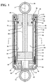
- FIGS. 1 and 2 a suspension damper assembly for an automotive shock absorber constructed in accordance with the subject invention is shown generally in FIGS. 1 and 2 .
- a suspension damper for an automotive shock absorber includes an outer tube 20 generally having a cylindrical shape defining an outer tube inner wall 22 and an outer tube outer wall 24.
- the outer tube 20 extends concentrically about a center axis A between an open end 26 and a closed end 28.
- An inner tube 30 generally having a cylindrical shape defining an inner tube inner wall 32 and an inner tube outer wall 34 is disposed concentrically inside the outer tube 20 along the center axis A between a first end 36 and a second end 38.
- the outer tube 20 has an annular flange 40 disposed on the open end 26, and the annular flange 40 extends radially inwardly toward and perpendicular to the center axis A to define an opening to the inner tube 30 at the first end 36 thereof.
- the inner tube inner wall 32 is spaced radially from the center axis A defining a hydraulic chamber 42 generally having a cylindrical shape.
- the inner tube outer wall 34 is spaced radially from the outer tube inner wall 22 defining a diaphragm chamber 44 of cylindrical shape.
- a diaphragm 46 generally having a cylindrical shape is disposed concentrically between the inner tube outer wall 34 and the outer tube inner wall 22 along the center axis A inside the diaphragm chamber 44.
- the diaphragm 46 divides the diaphragm chamber 44 into two separate chambers, a high pressure gas chamber 48 disposed between the diaphragm 46 and the inner tube outer wall 34 and a fluid chamber 50 disposed between the diaphragm 46 and the outer tube inner wall 22.
- the diaphragm 46 could be made of any other gas impermeable elastomer,
- a gas charge seal 52 generally having a'S' shape is disposed annularly in the high pressure gas chamber 48 and abuts the annular flange 40.
- the gas charge seal is an o-ring or other seal ring.
- the gas charge seal 52 engages the inner tube outer wall 34 and the outer tube inner wall 22 at the second end 38 of the inner tube 30.
- the 'S' shape of the gas charge seal 52 defines an inward groove 54 opening annularly to the inner tube outer wall 34 as well as an outward groove 56 opening annularly to the outer tube inner wall 22.
- a first annular seal 58 is disposed in the inward groove 54 in sealing engagement with the inner tube outer wall 34, and a second annular seal 60 is disposed in the outward groove 56 in sealing engagement with the inner tube outer wall 34.
- a cap 62 engages the closed end 28 of the outer tube 20, sealing the closed end 28 of the outer tube 20.
- An inner tube base 64 of cylindrical shape defines an outer periphery 66 being disposed in the first end 36 of the inner tube 30 and engages the cap 62 at the closed end 28 of the outer tube 20.
- the inner tube base 64 defines an annular shoulder 68 receiving and abutting the first end 36 of the inner tube 30 with the outer periphery 66 of the inner tube base 64 being concentric with the inner tube outer wall 34.
- the inner tube base 64 further defines a central cavity 70 of hollow cylindrical shape being disposed concentrically in the inner tube base 64.
- the inner tube base 64 allows fluid communication between the hydraulic chamber 42 and the fluid chamber 50 by use of a plurality of radially disposed channels 72 extending perpendicular to the center axis A between the central cavity 70 and the fluid chamber 50.
- the inner tube base 64 is closed and sealed by the cap 62.
- a base cup could be used instead of using the cap 62.
- a piston 74 is disposed in sliding and sealing engagement with the inner tube inner wall 32 within the hydraulic chamber 42, and a rod guide 76 of cylindrical shape defines an axial bore 78 being disposed in the open end 26.
- the rod guide 76 is in a sealing engagement with the inner tube inner wall 32, with a piston rod 80 connected to the piston 74 and extending along the center axis A and through the bore in the rod guide 76.
- a lower mounting member 82 with a ring shape is disposed along the center axis A on the closed end 28 of the outer tube 20 and connected to the cap 62.
- the lower mounting member 82 receives a mounting device.
- An upper mounting member 86 with a ring shape is disposed along the center axis A on the piston rod 80 receiving a mounting device.
- the upper mounting member 86 can be secured to the piston rod 80 by screwing or welding the upper mounting member 86 to the piston rod 80.
- the diaphragm 46 is held in place radially inwardly by an inner clamp 88 of annular shape in a sealing engagement with the inner tube outer wall 34.
- the inner clamp 88 axially overlaps the first end 36 of the inner tube 30 and the tube base at the shoulder 68 of the inner tube base 64.
- a radially inwardly disposed waist 90 defines an annular projection of the outer tube 20 extending radially inwardly to define a sealing surface 92 adjacent to the open end 26 of the outer tube 20.
- the diaphragm 46 extends from under the inner clamp 88 and through a 'U' shaped turn back toward the open end 26 along outer tube inner wall 22 and over the waist 90.
- An upper clamp 94 of annular shape axially aligns with the waist 90 and holds the diaphragm 46 into the waist 90 of the outer tube inner wall 22, sealing the diaphragm 46 to the outer tube inner wall 22.
- the subject invention also includes a method for assembling a suspension damper for an automotive shock absorber comprising a first step of pressing the inner tube 30 onto the inner tube base 64 containing the central cavity 70 about the first end 36 of the inner tube 30, fitting one end of the diaphragm 46 over the inner tube outer wall 34 about the first end 36 of the inner tube 30.
- the fabrication continues by sealing the diaphragm 46 to the inner tube outer wall 34 adjacent the first end 36 by use of an inner clamp 88 defining an inner seal placed on the shoulder 68 between the inner tube 30 and the inner tube base 64. This seals the high pressure gas chamber 48 about the first end 36 of the inner tube 30.
- the diaphragm 46 is then pulled or rolled up the inner tube outer wall 34 over the inner clamp 88 and towards the second end 38 of the inner tube 30.
- the inner tube 30 the inner tube base 64 and the secured diaphragm 46 are inserted into the open end 26 of the outer tube 20.
- the closed end 28 of the outer tube 20 engages the cap 62, sealing the closed end 28 of the outer tube 20.
- the upper clamp 94 is lowered into the diaphragm chamber 44 from the open end 26 of the outer tube 20 between the diaphragm 46 and the inner tube outer wall 34.
- the upper clamp 94 is fitted to the diaphragm 46, separating the high pressure gas chamber 48 from the fluid chamber 50 inside the diaphragm chamber 44.
- a crimp force is applied to the outer tube outer wall 24 compressing the outer tube 20 and diaphragm 46 against the upper clamp 94 sealing the high pressure chamber at the open end 26.
- the crimp force creates the waist 90 in the outer tube 20 about the open end 26.
- the piston 74 and piston rod 80 are installed in the inner tube inner wall 32 and the hydraulic chamber 42 is filled with a hydraulic fluid.
- the rod guide 76 is installed over the piston rod 80 and encloses the hydraulic chamber 42.
- the high pressure gas chamber 48 is charged with a high pressure fluid then sealed by securing a gas charge seal 52 to the open end 26 of the diaphragm chamber 44.
- the high pressure fluid is nitrogen.
- the diaphragm chamber 44 is then closed by rolling the annular flange 40 of the outer tube 20 inwardly to abut the inner tube 30 and the gas charge seal 52.
Landscapes
- Engineering & Computer Science (AREA)
- General Engineering & Computer Science (AREA)
- Mechanical Engineering (AREA)
- Fluid-Damping Devices (AREA)
Claims (8)
- Aufhängungsdämpferanordnung für einen KfZ-Stoßdämpfer, umfassend;
ein Außenrohr (20) in zylindrischer Form mit einer Innenwand des Außenrohres (22) und einer Außenwand des Außenrohrs (24), das sich konzentrisch um die zentrale Achse zwischen dem offenen Ende (26) und dem geschlossenen Ende (28), erstreckt, ein Innenrohr (30) in zylindrischer Form mit einer Innenwand des Innenrohrs (32) und einer Außenwand des Innenrohrs (34), das konzentrisch um die genannte zentrale Achse und das genannte Außenrohr (20) die genannte zentrale Achse entlang zwischen dem ersten Ende (36) und dem zweiten Ende (38) angeordnet ist, einen Ringflansch (40), der am genannten offenen Ende (26) des genannten Außenrohrs (20) angeordnet ist und sich radial nach innen hin und senkrecht zur genannten zentralen Achse erstreckt und somit die öffnung des genannten Innenrohrs (30) am genannten ersten Ende (36) des Rohrs definiert,
die genannten Innenwand des Innenrohrs (32) radial von der genannten zentralen Achse, die die Hydraulikkammer (42) in zylindrischer Form definiert, die genannte Außenwand des Innenrohrs (34) radial von der genannten Innenwand des Außenrohrs (22), die die Membrankammer (44) in zylindrischer Form zwischen der genannten Außenwand des Innenrohrs (34) und der genannten Innenwand des Außenrohrs (22) definiert, eine Membrane (46) in zylindrischer Form konzentrisch zwischen der genannten Außenwand des Innenrohrs (34) und der genannten Innenwand des Außenrohrs (22), die zentrale Achse entlang, die die genannte Membrankammer (44) in Hochdruckgaskammer (48) zwischen der genannten Membrane (46) und der genannten Außenwand des Innenrohrs (34) und Flüssigkeitskammer (50) zwischen der genannten Membrane (46) und der genannten Innenwand des Außenrohrs (22) teilt, Dichtung der Gasfüllung (52), die ringförmig in der genannten Hochdruckgaskammer (48) angeordnet ist sowie die genannte Außenwand des Innenrohrs (34) und die genannten Innenwand des Außenrohrs (22) am genannten zweite Ende (38) des genannten Innenrohrs (30) verdichtet, eine Kappe (62) am genannten geschlossenen Ende (28) des genannten Außenrohrs (20) zur Abdichtung des genannten geschlossenen Ende (28),
ein Innenrohrboden (64) in zylindrischer Form, der den äußeren Umfang (66) definiert und am genannten ersten Ende (36) des genannten Innenrohrs (30) angeordnet ist sowie die genannte Kappe (62) am genannten geschlossenen Ende (28) des genannten Außenrohrs (20) eingreift,
den genannten Außenrohrboden (64), der den zentralen Hohlraum (70) in zylindrischer Form, angeordnet konzentrisch im genannten Innenrohrboden (64) definiert, in Richtung der genannten Hydraulikkammer (42) geöffnet und mit der genannten Kappe (62) geschlossen ist sowie eine Vielzahl von radial angeordneten Kanäle (72), die sich senkrecht zur genannten zentralen Achse zwischen dem genannten Hohlraum (70) und der genannten Flüssigkeitskammer (50) erstrecken und somit eine fließende Kommunikation zwischen der genannten Hydraulikkammer (42) und der genannten Flüssigkeitskammer ermöglichen, definiert,
einen Kolben (74), der in Gleit- und Dichtungseingriff mit genannter Innenwand des Innenrohrs (32) in der genannten Hydraulikkammer (42) angeordnet ist, eine Stangenführung (76) in zylindrischer Form, die eine axiale Bohrung (78) definiert und am genannten offenen Ende (26) und im Dichtungseingriff mit der genannten Innenwand des Innenrohrs (32) angeordnet ist,
eine Kolbenstange (80), die sich die genannte zentrale Achse und durch die genannte Bohrung (78) in der genannten Stangenführung (76) erstreckt und mit dem genannten Kolben (74) zur gemeinsamen Bewegung verbunden ist, dadurch gekennzeichnet, dass eine ringförmige Innenklemme (88) die Membrane (46) radial nach innen zum Dichtungseingriff der genannten Außenwand des Innenrohrs (34) hält,
sich die genannte Membrane (46) vom unteren Teil der genannten Klemme (88) und durch den U-förmigen Teil in Richtung des genannten offenen Endes (26) die Innenwand des Außenrohrs (22) entlang erstreckt, und die Aufhängungsdämpferanordnung die obere ringförmige Klemme (94) zum Halten der genannten Membrane (46) an der genannten Innenwand des Außenrohrs (22) umfasst, um die genannte Membrane (46) an der genannten Innenwand des Außenrohrs (22) zu verdichten. - Die Anordnung nach Anspruch 1 dadurch gekennzeichnet, dass sie eine radial nach ihnen gerichtete Verengung (90), die eine ringförmige Projektion des genannten Außenrohrs (20) definiert sowie sich radial nach innen erstreckt und die Dichtungsfläche (92), die an das genannte offene Ende (26) des genannten Außenrohrs (20) und der genannten oberen Klemme (94), die axial mit der genannten Verengung ausgerichtet ist (94), anliegt, um die genannte Membrane (46) zu halten, definiert.
- Die Anordnung nach Anspruch 1 dadurch gekennzeichnet, dass sie einen kreisförmigen Arm (68), der an dem genannten ersten Ende (36) des genannten Innenrohres (30) mit dem genannten äußeren Umfang (66) des genannten Innenrohrbodens (64) konzentrisch zu der genannten Außenwand des Innenrohrs (34) anliegt und es aufnimmt, umfasst.
- Die Anordnung nach Anspruch 2 dadurch gekennzeichnet, dass die Dichtung der Gasfüllung (52) die 'S'-Form hat und an den genannten Ringflansch (40) anliegt;
die genannte 'S'-Form der genannten Dichtung der Gasfüllung (52) die innere Nut (54), die ringförmig zur genannten Außenwand des Innenrohrs (34) öffnet und eine externe Nut (56), die ringförmig zur genannten Innenwand des Außenrohrs (22) öffnet, definiert wobei die Aufhängungsdämpferanordnung die erste ringförmige Dichtung (58) in der genannten inneren Nut (54) im Dichtungseingriff mit der genannten Außenwand des Innenrohrs (34) und die zweite ringförmige Dichtung (60) in der genannten externen Nut (56) im Dichtungseingriff mit der genannten Innenwand des Außenrohrs (34) umfasst, wobei der Innenrohrboden (64) den kreisförmigen Arm (68), der an dem genannten ersten Ende (36) des genannten Innenrohres (30) mit dem genannten äußeren Umfang (66) des genannten Außenrohrbodens (64) konzentrisch zu der genannten Außenwand des Innenrohrs (34) anliegt und es aufnimmt, definiert;
wobei die Aufhängungsdämpferanordnung eine untere Aufnahme (82) in ringförmiger Form, die die zentrale Achse entlang am genannten geschlossenen Ende (28) angeordnet und mit der genannten Kappe (62) verbunden ist und auf die Art und Weise eine Aufnahme für die Montagevorrichtung bildet sowie
eine obere Aufnahme (86) in ringförmiger Form, die die zentrale Achse entlang an der Kolbenstange (80) angeordnet ist und auf die Art und Weise eine Aufnahme für die Montagevorrichtung bildet, umfasst,
wobei sich die genannten Innenklemme (88) und das genannte erste Ende (36) des genannten Innenrohrs (30) und der genannte Rohrboden (64) am genannten Arm (68) überlappen, und
sich die genannte Membrane (46) vom unteren Bereich der genannten Innenklemme (88) und durch den U-förmigen Teil in Richtung des genannten offenen Endes (26) die Innenwand des Außenrohrs (22) entlang und über der genannten Verengung (90) erstreckt. - Verfahren zur Montage des Aufhängungsdämpfers unter Anwendung des Innenrohrs (30), des Außenrohrs (20), der Membrankammer (44), angeordnet zwischen dem Innenrohr (30) und dem Außenrohr (20), der Membrane (46), angeordnet in der Membrankammer (44), die die Membrankammer (44) von der Hochdruckgaskammer (48) und der Flüssigkeitskammer (50) trennt; das genannte Verfahren umfasst folgende Schritte; Anordnung eines Endes der Membrane (46) über dem ersten Ende (36) des Innenrohrs (30),
Verdichtung der Membrane (46) an der Außenseite des Innenrohrs (30) anliegend an das erste Ende (36) des Rohrs, um die innere Verdichtung zu definieren,
Rollen der Membrane (46) über der inneren Dichtung und in Richtung des zweiten Ende (38) des Innenrohrs (30),
Einführen des Innenrohrs (30) und der Membrane (46) in das offene Ende (26) des Außenrohrs (20),
dadurch gekennzeichnet, dass die Membrane (46) an der Innenseite des Außenrohrs (20) verdichtet ist und an das zweite Ende (38) des Innenrohrs (30) anliegt. - Das Verfahren nach Anspruch 5 dadurch gekennzeichnet, dass es die Einwirkung der Crimpkraft auf die Außenwand des Außenrohrs (24), die das Außenrohr (20) und die Membrane (46) mit der oberen Klemme (94) zusammendrückt und dadurch die Hochdruckgaskammer (48) in der Nähe des offenen Endes (26) verdichtet und den Umfang (90) der Außenwand des Außenrohrs (24) bildet, umfasst.
- Das Verfahren nach Anspruch 5 dadurch gekennzeichnet, dass es die Verdichtung der Membrane (46) an der Außenwand des Innenrohrs (34), die an das erste Ende (36) des Rohrs anliegt, um die innere Dichtung am Arm (68) zwischen dem Innenrohr (30) und dem Innenrohrboden (64) definiert und dadurch die Hochdruckgaskammer (48) in der Nähe des geschlossenen Endes (28), umfasst.
- Das Verfahren nach Anspruch 6 dadurch gekennzeichnet, dass der Aufhängungsdämpfer ein KfZ-Stoßdämpfer ist und das Innenrohr (30) die Hydraulikkammer (42) und die Innenwand des Innenrohres (32) und die Außenwand des Innenrohrs (34) definiert, das Außenrohr (20) die Innenwand des Außenrohrs (22) und die Außenwand des Außenrohrs (24) definiert, das Innenrohr (30) das erste Ende (36) und das zweite Ende (38) hat und das Außenrohr (20) das offene Ende (26) und das geschlossene Ende (28) hat, Außenrohr (20) einen Ringflansch (40) hat, die Membrankammer (44) zwischen der Außenwand des Innenrohrs (34) und der Innenwand des Außenrohrs (22) angeordnet ist, wobei das Verfahren den Innenrohrboden (64) umfassend den zentralen Hohlraum (70) und den Arm (68), die Verengung (90) in der Außenwand des Außenrohrs (24), die Dichtung der Gasfüllung (52) und die Stangenführung (76), den Kolben (74) und die Kolbenstange (80), angeordnet in der Hydraulikkammer (42), eine Kappe (62) und eine untere Halterung und eine obere Halterung sowie eine Innenklemme (88) und eine obere Klemme (94) verwendet,
wobei das genannte Verfahren folgendes umfasst:Pressen des Innenrohrs (30) in den Innenrohrboden (64), umfassend den zentralen Hohlraum (70) in der Nähe des ersten Ende (36) des Innenrohrs (30),wobei der Schritt, in dem ein Ende der Membrane (46) über dem ersten Ende (36) des Innenrohrs (30) angeordnet wird, detailliert folgendes umfasst : Anordnung des ersten Endes der Membrane (46) über dem ersten Ende (36) der Außenwand des Innenrohrs (34) in der Nähe des ersten Ende (36) des Innenrohrs (30),der Schritt, in dem die Membrane (46) an der Außenwand des Innenrohrs (30), die an das erste Ende (36) des Rohrs anliegt, verdichtet wird, detailliert folgendes umfasst: Verdichtung der Membrane (46) an der Außenwand des Innenrohrs (34), die an das erste Ende (36) des Rohrs anliegt, um die Innendichtung am Arm zwischen dem Innenrohr (30) und dem Innenrohrboden (64) zu definieren und dadurch die Hochdruckgaskammer (48) in der Nähe des geschlossenen Endes (28) zu verdichten,der Schritt des Einführens des Innenrohrs (30) und der Membrane (46) in das offene Ende (26) des Außenrohrs (20), insbesondere:Einführen des Innenrohrs (30) und des Innenrohrbodens (64) und der Membrane (46) in das offene Ende (26) des Außenrohrs (20),wobei das genannte Verfahren folgendes umfasst: Installation der Kappe (62) und der unteren Halterung am geschlossenen Ende (28) des Außenrohrs (20) über dem Innenrohrboden (64) und Verdichtung des geschlossenen Endes (28) des Außenrohrs (20),Senken der oberen Klemme (94) in die Membrankammer (44) von dem offenen Ende (26) des Außenrohrs (20) zwischen der Membrane (46) und der Außenwand des Innenrohrs (34),Anpassung der oberen Klemme (94) an die Membrane (46), die die Hochdruckgaskammer (48) von der Flüssigkeitskammer (50) innerhalb der Membrankammer (44) trennt,Installation des Kolbens (74) und der Kolbenstange (80) in der Innenwand es Innenrohrs,Befüllung der Hydraulikkammer (42) mit der Hydraulikflüssigkeit,Befüllung der Hochdruckgaskammer (48) mit der Druckflüssigkeit,Verdichtung der Hochdruckgaskammer (48) durch Anordnung der Dichtung der Gasfüllung (52) in der Membrankammer (44),Verschließung der Membrankammer (44) durch Rollen des Ringflansches (40) des Außenrohrs (20) nach innen in der Nähe des Innenrohrs (30) und der Dichtung der Gasfüllung (52),Installation der oberen Halterung an der Kolbenstange (80) am offenen Ende (26) und Befüllung der Hochdruckgaskammer (48) mit der Druckflüssigkeit.
Applications Claiming Priority (2)
| Application Number | Priority Date | Filing Date | Title |
|---|---|---|---|
| US201261653104P | 2012-05-30 | 2012-05-30 | |
| PCT/CN2012/078182 WO2013177844A1 (en) | 2012-05-30 | 2012-07-04 | A suspension damper assembly |
Publications (3)
| Publication Number | Publication Date |
|---|---|
| EP2855966A1 EP2855966A1 (de) | 2015-04-08 |
| EP2855966A4 EP2855966A4 (de) | 2016-04-13 |
| EP2855966B1 true EP2855966B1 (de) | 2016-10-12 |
Family
ID=49672328
Family Applications (1)
| Application Number | Title | Priority Date | Filing Date |
|---|---|---|---|
| EP12877969.1A Active EP2855966B1 (de) | 2012-05-30 | 2012-07-04 | Aufhängungsdämpferanordnung |
Country Status (7)
| Country | Link |
|---|---|
| US (1) | US9334917B2 (de) |
| EP (1) | EP2855966B1 (de) |
| JP (1) | JP5698880B2 (de) |
| CN (1) | CN104364552B (de) |
| ES (1) | ES2612183T3 (de) |
| PL (1) | PL2855966T3 (de) |
| WO (1) | WO2013177844A1 (de) |
Families Citing this family (10)
| Publication number | Priority date | Publication date | Assignee | Title |
|---|---|---|---|---|
| CN104895991B (zh) * | 2015-05-24 | 2017-12-29 | 珠海市业成轨道交通设备科技有限公司 | 卧式油气不分隔缓冲器 |
| CN107606023B (zh) * | 2017-09-06 | 2019-08-02 | 包头轻工职业技术学院 | 减震器 |
| CN108571557B (zh) * | 2018-05-30 | 2024-07-02 | 宁波麦维科技有限公司 | 往复式阻尼器 |
| CN108547901B (zh) * | 2018-06-19 | 2020-09-04 | 四川立地车辆底盘科技有限公司 | 悬架气体弹簧调刚度的方法 |
| CN109340294A (zh) * | 2018-12-12 | 2019-02-15 | 河海大学常州校区 | 一种副油箱带气囊的液压阻尼器 |
| CN109340295A (zh) * | 2018-12-12 | 2019-02-15 | 河海大学常州校区 | 一种副油箱带气囊的液压阻尼器 |
| KR102015014B1 (ko) * | 2019-02-08 | 2019-08-29 | (주)케이시엠모터스 | 차량용 쇼크 업소버 |
| DE102019131319A1 (de) * | 2019-11-20 | 2021-05-20 | Thyssenkrupp Ag | Schwingungsdämpfer und Kraftfahrzeug mit einem solchen Schwingungsdämpfer |
| DE102020210538A1 (de) * | 2020-08-19 | 2022-02-24 | Thyssenkrupp Ag | Schwingungsdämpfer und ein Dämpferrohr für einen Schwingungsdämpfer |
| CN116538222B (zh) * | 2023-02-25 | 2025-11-11 | 安徽工业技术创新研究院六安院 | 一种高频用折叠薄壁管减振器 |
Family Cites Families (36)
| Publication number | Priority date | Publication date | Assignee | Title |
|---|---|---|---|---|
| GB864703A (en) * | 1958-08-01 | 1961-04-06 | Armstrong Patents Co Ltd | Improvements in or relating to hydraulic shock absorbers |
| BE620789A (de) * | 1959-06-20 | |||
| GB1084575A (en) | 1964-10-20 | 1967-09-27 | Armstrong Patents Co Ltd | Improvements in and relating to telescopic hydraulic shock absorbers |
| DE1630058B1 (de) * | 1967-10-09 | 1971-10-28 | Hoesch Ag | Hydropneumatisches Federbein mit innerer Niveauregeleinrichtung |
| US3527451A (en) * | 1968-05-13 | 1970-09-08 | Gen Motors Corp | Shock absorber with pressurizable reservoir chamber |
| BE790144A (fr) * | 1971-10-22 | 1973-04-16 | Hoesch Ag | Jambe de force a ressort hydropneumatique dotee d'un regulateurde niveau interne |
| US3771626A (en) * | 1972-04-04 | 1973-11-13 | Monroe Auto Equipment Co | Pressurized shock absorber |
| US3874485A (en) * | 1972-05-01 | 1975-04-01 | Gen Motors Corp | Oleo-pneumatic shock absorber |
| US3798744A (en) * | 1972-05-01 | 1974-03-26 | Gen Motors Corp | A procedure for charging an oleo-pneumatic shock absorber |
| US3819166A (en) * | 1972-10-12 | 1974-06-25 | Gen Motors Corp | Gas bladder for combination liquid gas suspension device |
| FR2207563A5 (de) * | 1972-11-17 | 1974-06-14 | Allinquant Fernand | |
| US4105193A (en) * | 1976-11-26 | 1978-08-08 | General Motors Corporation | Shock absorber and leveling unit with auxiliary damping device for vehicle suspensions |
| JPS58184333A (ja) * | 1982-04-22 | 1983-10-27 | Atsugi Motor Parts Co Ltd | 液圧緩衝器 |
| DE3706738A1 (de) * | 1987-03-02 | 1988-09-15 | Aros Hydraulik | Hydraulischer stoss- und schwingungsdaempfer |
| ES2121494B1 (es) * | 1994-01-31 | 1999-06-16 | Fichtel & Sachs Ah | Amortiguador neumatico. |
| JP3696671B2 (ja) * | 1995-09-29 | 2005-09-21 | カヤバ工業株式会社 | 車高調整装置 |
| US6161662A (en) * | 1999-03-16 | 2000-12-19 | Delphi Technologies, Inc. | Suspension damper for motor vehicle |
| DE19961719A1 (de) * | 1999-12-21 | 2001-07-05 | Daimler Chrysler Ag | Feder-Dämpfersystem mit Schlauchrollbalg |
| WO2002085183A2 (en) * | 2001-04-19 | 2002-10-31 | Progressive Suspension, Inc. | Bladder for use in a damping device |
| US6695105B2 (en) * | 2001-09-12 | 2004-02-24 | Kayaba Industry Co., Ltd. | Hydraulic shock absorber |
| US20040262107A1 (en) * | 2001-09-24 | 2004-12-30 | Srinath Nandyal | Shock absorber having a pressurized gas compartment |
| DE20115980U1 (de) * | 2001-09-28 | 2001-12-06 | PATEC Fahrwerktechnik GmbH, 58640 Iserlohn | Hydraulischer Teleskopdämpfer |
| DE10244002A1 (de) | 2002-09-21 | 2004-04-01 | Fte Automotive Gmbh & Co. Kg | Unterdruck-Bremskraftverstärker für eine Hilfskraft-Bremsanlage für Kraftfahrzeuge |
| JP4181940B2 (ja) * | 2003-08-01 | 2008-11-19 | カヤバ工業株式会社 | リリーフ弁および車高調整機能付油圧緩衝器 |
| JP2008190691A (ja) * | 2007-02-07 | 2008-08-21 | Hitachi Ltd | 油圧緩衝器 |
| JP4883703B2 (ja) * | 2007-07-31 | 2012-02-22 | カヤバ工業株式会社 | 複筒型緩衝器 |
| JP5077549B2 (ja) * | 2007-10-31 | 2012-11-21 | 日立オートモティブシステムズ株式会社 | 油圧緩衝器の製造方法 |
| KR101162306B1 (ko) * | 2008-03-05 | 2012-07-04 | 주식회사 만도 | 차고 조정식 쇽업소버 |
| CN201249758Y (zh) | 2008-07-30 | 2009-06-03 | 上海汽车制动系统有限公司 | 真空助力器 |
| CN201380843Y (zh) | 2009-03-26 | 2010-01-13 | 上海汽车制动系统有限公司 | 双助力比真空助力器 |
| CN101844555A (zh) | 2009-03-26 | 2010-09-29 | 上海汽车制动系统有限公司 | 气压助力器 |
| JP5426431B2 (ja) * | 2009-06-30 | 2014-02-26 | 株式会社ショーワ | 油圧緩衝器 |
| US8240642B2 (en) | 2010-02-12 | 2012-08-14 | Bwi Company Limited S.A. | Fluid damper with internal compression spring |
| CN201651147U (zh) * | 2010-03-11 | 2010-11-24 | 励明夫 | 大双筒高压减震器 |
| CN102050101A (zh) | 2010-12-29 | 2011-05-11 | 温州市东启汽车零部件制造有限公司 | 真空助力器紧急制动装置 |
| CN203472841U (zh) | 2013-09-30 | 2014-03-12 | 京西重工(上海)有限公司 | 双助比制动真空助力器 |
-
2012
- 2012-07-04 ES ES12877969.1T patent/ES2612183T3/es active Active
- 2012-07-04 JP JP2014539217A patent/JP5698880B2/ja active Active
- 2012-07-04 WO PCT/CN2012/078182 patent/WO2013177844A1/en not_active Ceased
- 2012-07-04 PL PL12877969T patent/PL2855966T3/pl unknown
- 2012-07-04 CN CN201280073648.0A patent/CN104364552B/zh active Active
- 2012-07-04 US US14/350,540 patent/US9334917B2/en active Active
- 2012-07-04 EP EP12877969.1A patent/EP2855966B1/de active Active
Also Published As
| Publication number | Publication date |
|---|---|
| JP2014532846A (ja) | 2014-12-08 |
| US9334917B2 (en) | 2016-05-10 |
| EP2855966A1 (de) | 2015-04-08 |
| CN104364552B (zh) | 2015-10-07 |
| JP5698880B2 (ja) | 2015-04-08 |
| WO2013177844A1 (en) | 2013-12-05 |
| PL2855966T3 (pl) | 2017-05-31 |
| CN104364552A (zh) | 2015-02-18 |
| ES2612183T3 (es) | 2017-05-12 |
| US20150300441A1 (en) | 2015-10-22 |
| EP2855966A4 (de) | 2016-04-13 |
Similar Documents
| Publication | Publication Date | Title |
|---|---|---|
| US9334917B2 (en) | Suspension damper assembly | |
| US9206874B2 (en) | Damper with air spring | |
| US4960188A (en) | Single-tube vibration damper of variable damping force | |
| US4044866A (en) | Method for filling gas into gas spring | |
| EP3153738A1 (de) | Stossdämpfer mit hydraulischem rückschlagsystem | |
| KR20180091875A (ko) | 자동차용 진동 댐퍼 | |
| CA2402768C (en) | Hydraulic shock absorber | |
| EP3072711B1 (de) | Luftfederung | |
| US4508201A (en) | Piston rod with an integral piston for a shock absorber | |
| US4114866A (en) | Gas filling arrangement for a telescopic suspension unit | |
| JP6744983B2 (ja) | 特に電子式にスリップ制御可能な車両ブレーキ設備の液圧ユニットのハウジングブロック | |
| CN106460993A (zh) | 用于减振器的阻尼阀装置 | |
| JP7067885B2 (ja) | フロントフォーク、及びフロントフォークの製造方法 | |
| KR102138416B1 (ko) | 실린더 장치 | |
| US20160200284A1 (en) | High-pressure gas cylinder | |
| US10359115B2 (en) | Cylinder device and seal member | |
| WO2008076176A3 (en) | New top cap crimping for air spring suspension | |
| CN110748596B (zh) | 用于引导单管减震器的环形密封单元 | |
| KR100925006B1 (ko) | 자동차용 탄성 에너지 시스템 | |
| US20030178268A1 (en) | Suspension damper mounting ring casting with steel insert | |
| EP4224034A1 (de) | Hydraulischer endanschlag für einzelrohrdämpfer | |
| EP2413002A1 (de) | Motorradgabelanordnung mit Einstellsystem für Ausgleichsfeder | |
| JPH0316537B2 (de) | ||
| JP6295114B2 (ja) | 正立型グリス摺動フロントフォークとこれを備えた車輪懸架装置 | |
| JP2001200878A (ja) | アルミシングルチューブダンパ |
Legal Events
| Date | Code | Title | Description |
|---|---|---|---|
| PUAI | Public reference made under article 153(3) epc to a published international application that has entered the european phase |
Free format text: ORIGINAL CODE: 0009012 |
|
| 17P | Request for examination filed |
Effective date: 20140828 |
|
| AK | Designated contracting states |
Kind code of ref document: A1 Designated state(s): AL AT BE BG CH CY CZ DE DK EE ES FI FR GB GR HR HU IE IS IT LI LT LU LV MC MK MT NL NO PL PT RO RS SE SI SK SM TR |
|
| AX | Request for extension of the european patent |
Extension state: BA ME |
|
| DAX | Request for extension of the european patent (deleted) | ||
| RA4 | Supplementary search report drawn up and despatched (corrected) |
Effective date: 20160314 |
|
| RIC1 | Information provided on ipc code assigned before grant |
Ipc: F16F 9/19 20060101AFI20160308BHEP Ipc: F16F 9/06 20060101ALI20160308BHEP |
|
| RIC1 | Information provided on ipc code assigned before grant |
Ipc: F16F 9/06 20060101ALI20160519BHEP Ipc: F16F 9/19 20060101AFI20160519BHEP |
|
| GRAP | Despatch of communication of intention to grant a patent |
Free format text: ORIGINAL CODE: EPIDOSNIGR1 |
|
| INTG | Intention to grant announced |
Effective date: 20160714 |
|
| GRAS | Grant fee paid |
Free format text: ORIGINAL CODE: EPIDOSNIGR3 |
|
| GRAA | (expected) grant |
Free format text: ORIGINAL CODE: 0009210 |
|
| AK | Designated contracting states |
Kind code of ref document: B1 Designated state(s): AL AT BE BG CH CY CZ DE DK EE ES FI FR GB GR HR HU IE IS IT LI LT LU LV MC MK MT NL NO PL PT RO RS SE SI SK SM TR |
|
| REG | Reference to a national code |
Ref country code: GB Ref legal event code: FG4D |
|
| REG | Reference to a national code |
Ref country code: CH Ref legal event code: EP |
|
| REG | Reference to a national code |
Ref country code: AT Ref legal event code: REF Ref document number: 836823 Country of ref document: AT Kind code of ref document: T Effective date: 20161015 |
|
| REG | Reference to a national code |
Ref country code: IE Ref legal event code: FG4D |
|
| REG | Reference to a national code |
Ref country code: DE Ref legal event code: R096 Ref document number: 602012024218 Country of ref document: DE |
|
| RAP2 | Party data changed (patent owner data changed or rights of a patent transferred) |
Owner name: BEIJINGWEST INDUSTRIES CO. LTD. |
|
| REG | Reference to a national code |
Ref country code: RO Ref legal event code: EPE |
|
| REG | Reference to a national code |
Ref country code: LT Ref legal event code: MG4D |
|
| REG | Reference to a national code |
Ref country code: NL Ref legal event code: MP Effective date: 20161012 |
|
| PG25 | Lapsed in a contracting state [announced via postgrant information from national office to epo] |
Ref country code: LV Free format text: LAPSE BECAUSE OF FAILURE TO SUBMIT A TRANSLATION OF THE DESCRIPTION OR TO PAY THE FEE WITHIN THE PRESCRIBED TIME-LIMIT Effective date: 20161012 |
|
| REG | Reference to a national code |
Ref country code: AT Ref legal event code: MK05 Ref document number: 836823 Country of ref document: AT Kind code of ref document: T Effective date: 20161012 |
|
| PG25 | Lapsed in a contracting state [announced via postgrant information from national office to epo] |
Ref country code: NO Free format text: LAPSE BECAUSE OF FAILURE TO SUBMIT A TRANSLATION OF THE DESCRIPTION OR TO PAY THE FEE WITHIN THE PRESCRIBED TIME-LIMIT Effective date: 20170112 Ref country code: GR Free format text: LAPSE BECAUSE OF FAILURE TO SUBMIT A TRANSLATION OF THE DESCRIPTION OR TO PAY THE FEE WITHIN THE PRESCRIBED TIME-LIMIT Effective date: 20170113 Ref country code: SE Free format text: LAPSE BECAUSE OF FAILURE TO SUBMIT A TRANSLATION OF THE DESCRIPTION OR TO PAY THE FEE WITHIN THE PRESCRIBED TIME-LIMIT Effective date: 20161012 Ref country code: LT Free format text: LAPSE BECAUSE OF FAILURE TO SUBMIT A TRANSLATION OF THE DESCRIPTION OR TO PAY THE FEE WITHIN THE PRESCRIBED TIME-LIMIT Effective date: 20161012 |
|
| REG | Reference to a national code |
Ref country code: ES Ref legal event code: FG2A Ref document number: 2612183 Country of ref document: ES Kind code of ref document: T3 Effective date: 20170512 |
|
| PG25 | Lapsed in a contracting state [announced via postgrant information from national office to epo] |
Ref country code: NL Free format text: LAPSE BECAUSE OF FAILURE TO SUBMIT A TRANSLATION OF THE DESCRIPTION OR TO PAY THE FEE WITHIN THE PRESCRIBED TIME-LIMIT Effective date: 20161012 Ref country code: HR Free format text: LAPSE BECAUSE OF FAILURE TO SUBMIT A TRANSLATION OF THE DESCRIPTION OR TO PAY THE FEE WITHIN THE PRESCRIBED TIME-LIMIT Effective date: 20161012 Ref country code: BE Free format text: LAPSE BECAUSE OF FAILURE TO SUBMIT A TRANSLATION OF THE DESCRIPTION OR TO PAY THE FEE WITHIN THE PRESCRIBED TIME-LIMIT Effective date: 20161012 Ref country code: AT Free format text: LAPSE BECAUSE OF FAILURE TO SUBMIT A TRANSLATION OF THE DESCRIPTION OR TO PAY THE FEE WITHIN THE PRESCRIBED TIME-LIMIT Effective date: 20161012 Ref country code: FI Free format text: LAPSE BECAUSE OF FAILURE TO SUBMIT A TRANSLATION OF THE DESCRIPTION OR TO PAY THE FEE WITHIN THE PRESCRIBED TIME-LIMIT Effective date: 20161012 Ref country code: PT Free format text: LAPSE BECAUSE OF FAILURE TO SUBMIT A TRANSLATION OF THE DESCRIPTION OR TO PAY THE FEE WITHIN THE PRESCRIBED TIME-LIMIT Effective date: 20170213 Ref country code: RS Free format text: LAPSE BECAUSE OF FAILURE TO SUBMIT A TRANSLATION OF THE DESCRIPTION OR TO PAY THE FEE WITHIN THE PRESCRIBED TIME-LIMIT Effective date: 20161012 Ref country code: IS Free format text: LAPSE BECAUSE OF FAILURE TO SUBMIT A TRANSLATION OF THE DESCRIPTION OR TO PAY THE FEE WITHIN THE PRESCRIBED TIME-LIMIT Effective date: 20170212 |
|
| REG | Reference to a national code |
Ref country code: FR Ref legal event code: PLFP Year of fee payment: 6 |
|
| REG | Reference to a national code |
Ref country code: DE Ref legal event code: R097 Ref document number: 602012024218 Country of ref document: DE |
|
| PG25 | Lapsed in a contracting state [announced via postgrant information from national office to epo] |
Ref country code: SK Free format text: LAPSE BECAUSE OF FAILURE TO SUBMIT A TRANSLATION OF THE DESCRIPTION OR TO PAY THE FEE WITHIN THE PRESCRIBED TIME-LIMIT Effective date: 20161012 Ref country code: EE Free format text: LAPSE BECAUSE OF FAILURE TO SUBMIT A TRANSLATION OF THE DESCRIPTION OR TO PAY THE FEE WITHIN THE PRESCRIBED TIME-LIMIT Effective date: 20161012 Ref country code: DK Free format text: LAPSE BECAUSE OF FAILURE TO SUBMIT A TRANSLATION OF THE DESCRIPTION OR TO PAY THE FEE WITHIN THE PRESCRIBED TIME-LIMIT Effective date: 20161012 |
|
| PLBE | No opposition filed within time limit |
Free format text: ORIGINAL CODE: 0009261 |
|
| STAA | Information on the status of an ep patent application or granted ep patent |
Free format text: STATUS: NO OPPOSITION FILED WITHIN TIME LIMIT |
|
| PG25 | Lapsed in a contracting state [announced via postgrant information from national office to epo] |
Ref country code: BG Free format text: LAPSE BECAUSE OF FAILURE TO SUBMIT A TRANSLATION OF THE DESCRIPTION OR TO PAY THE FEE WITHIN THE PRESCRIBED TIME-LIMIT Effective date: 20170112 Ref country code: SM Free format text: LAPSE BECAUSE OF FAILURE TO SUBMIT A TRANSLATION OF THE DESCRIPTION OR TO PAY THE FEE WITHIN THE PRESCRIBED TIME-LIMIT Effective date: 20161012 |
|
| 26N | No opposition filed |
Effective date: 20170713 |
|
| PG25 | Lapsed in a contracting state [announced via postgrant information from national office to epo] |
Ref country code: SI Free format text: LAPSE BECAUSE OF FAILURE TO SUBMIT A TRANSLATION OF THE DESCRIPTION OR TO PAY THE FEE WITHIN THE PRESCRIBED TIME-LIMIT Effective date: 20161012 |
|
| REG | Reference to a national code |
Ref country code: CH Ref legal event code: PL |
|
| REG | Reference to a national code |
Ref country code: IE Ref legal event code: MM4A |
|
| PG25 | Lapsed in a contracting state [announced via postgrant information from national office to epo] |
Ref country code: LI Free format text: LAPSE BECAUSE OF NON-PAYMENT OF DUE FEES Effective date: 20170731 Ref country code: IE Free format text: LAPSE BECAUSE OF NON-PAYMENT OF DUE FEES Effective date: 20170704 Ref country code: CH Free format text: LAPSE BECAUSE OF NON-PAYMENT OF DUE FEES Effective date: 20170731 |
|
| REG | Reference to a national code |
Ref country code: FR Ref legal event code: PLFP Year of fee payment: 7 |
|
| PG25 | Lapsed in a contracting state [announced via postgrant information from national office to epo] |
Ref country code: LU Free format text: LAPSE BECAUSE OF NON-PAYMENT OF DUE FEES Effective date: 20170704 |
|
| PG25 | Lapsed in a contracting state [announced via postgrant information from national office to epo] |
Ref country code: MT Free format text: LAPSE BECAUSE OF NON-PAYMENT OF DUE FEES Effective date: 20170704 |
|
| PG25 | Lapsed in a contracting state [announced via postgrant information from national office to epo] |
Ref country code: HU Free format text: LAPSE BECAUSE OF FAILURE TO SUBMIT A TRANSLATION OF THE DESCRIPTION OR TO PAY THE FEE WITHIN THE PRESCRIBED TIME-LIMIT; INVALID AB INITIO Effective date: 20120704 Ref country code: MC Free format text: LAPSE BECAUSE OF FAILURE TO SUBMIT A TRANSLATION OF THE DESCRIPTION OR TO PAY THE FEE WITHIN THE PRESCRIBED TIME-LIMIT Effective date: 20161012 |
|
| PG25 | Lapsed in a contracting state [announced via postgrant information from national office to epo] |
Ref country code: CY Free format text: LAPSE BECAUSE OF FAILURE TO SUBMIT A TRANSLATION OF THE DESCRIPTION OR TO PAY THE FEE WITHIN THE PRESCRIBED TIME-LIMIT Effective date: 20161012 |
|
| PG25 | Lapsed in a contracting state [announced via postgrant information from national office to epo] |
Ref country code: MK Free format text: LAPSE BECAUSE OF FAILURE TO SUBMIT A TRANSLATION OF THE DESCRIPTION OR TO PAY THE FEE WITHIN THE PRESCRIBED TIME-LIMIT Effective date: 20161012 |
|
| PG25 | Lapsed in a contracting state [announced via postgrant information from national office to epo] |
Ref country code: TR Free format text: LAPSE BECAUSE OF FAILURE TO SUBMIT A TRANSLATION OF THE DESCRIPTION OR TO PAY THE FEE WITHIN THE PRESCRIBED TIME-LIMIT Effective date: 20161012 |
|
| PG25 | Lapsed in a contracting state [announced via postgrant information from national office to epo] |
Ref country code: AL Free format text: LAPSE BECAUSE OF FAILURE TO SUBMIT A TRANSLATION OF THE DESCRIPTION OR TO PAY THE FEE WITHIN THE PRESCRIBED TIME-LIMIT Effective date: 20161012 |
|
| PGFP | Annual fee paid to national office [announced via postgrant information from national office to epo] |
Ref country code: PL Payment date: 20250530 Year of fee payment: 14 |
|
| PGFP | Annual fee paid to national office [announced via postgrant information from national office to epo] |
Ref country code: GB Payment date: 20250529 Year of fee payment: 14 |
|
| PGFP | Annual fee paid to national office [announced via postgrant information from national office to epo] |
Ref country code: FR Payment date: 20250610 Year of fee payment: 14 |
|
| PGFP | Annual fee paid to national office [announced via postgrant information from national office to epo] |
Ref country code: RO Payment date: 20250624 Year of fee payment: 14 |
|
| PGFP | Annual fee paid to national office [announced via postgrant information from national office to epo] |
Ref country code: CZ Payment date: 20250618 Year of fee payment: 14 |
|
| PGFP | Annual fee paid to national office [announced via postgrant information from national office to epo] |
Ref country code: ES Payment date: 20250804 Year of fee payment: 14 |
|
| PGFP | Annual fee paid to national office [announced via postgrant information from national office to epo] |
Ref country code: DE Payment date: 20250604 Year of fee payment: 14 |
|
| PGFP | Annual fee paid to national office [announced via postgrant information from national office to epo] |
Ref country code: IT Payment date: 20250623 Year of fee payment: 14 |