EP2856598B1 - Bidirektionale leistungswandler mit steuerung der eingangswechselspannung - Google Patents
Bidirektionale leistungswandler mit steuerung der eingangswechselspannung Download PDFInfo
- Publication number
- EP2856598B1 EP2856598B1 EP13797168.5A EP13797168A EP2856598B1 EP 2856598 B1 EP2856598 B1 EP 2856598B1 EP 13797168 A EP13797168 A EP 13797168A EP 2856598 B1 EP2856598 B1 EP 2856598B1
- Authority
- EP
- European Patent Office
- Prior art keywords
- voltage
- power
- control
- mains
- input
- Prior art date
- Legal status (The legal status is an assumption and is not a legal conclusion. Google has not performed a legal analysis and makes no representation as to the accuracy of the status listed.)
- Active
Links
Images




Classifications
-
- H—ELECTRICITY
- H02—GENERATION; CONVERSION OR DISTRIBUTION OF ELECTRIC POWER
- H02J—ELECTRIC POWER NETWORKS; CIRCUIT ARRANGEMENTS OR SYSTEMS FOR SUPPLYING OR DISTRIBUTING ELECTRIC POWER; SYSTEMS FOR STORING ELECTRIC ENERGY
- H02J3/00—Circuit arrangements for AC mains or AC distribution networks
- H02J3/38—Arrangements for feeding a single network from two or more generators or sources in parallel; Arrangements for feeding already energised networks from additional generators or sources in parallel
- H02J3/40—Synchronisation of generators for connection to a network or to another generator
- H02J3/44—Synchronisation of generators for connection to a network or to another generator with means for ensuring correct phase sequence
-
- H—ELECTRICITY
- H02—GENERATION; CONVERSION OR DISTRIBUTION OF ELECTRIC POWER
- H02J—ELECTRIC POWER NETWORKS; CIRCUIT ARRANGEMENTS OR SYSTEMS FOR SUPPLYING OR DISTRIBUTING ELECTRIC POWER; SYSTEMS FOR STORING ELECTRIC ENERGY
- H02J3/00—Circuit arrangements for AC mains or AC distribution networks
- H02J3/18—Arrangements for adjusting, eliminating or compensating reactive power in networks
- H02J3/1807—Arrangements for adjusting, eliminating or compensating reactive power in networks using series compensators, e.g. thyristor-controlled series capacitors [TCSC]
- H02J3/1814—Arrangements for adjusting, eliminating or compensating reactive power in networks using series compensators, e.g. thyristor-controlled series capacitors [TCSC] having reactive elements actively controlled by bridge converters, e.g. unified power flow controllers [UPFC] or controlled series voltage compensators
-
- H—ELECTRICITY
- H02—GENERATION; CONVERSION OR DISTRIBUTION OF ELECTRIC POWER
- H02M—APPARATUS FOR CONVERSION BETWEEN AC AND AC, BETWEEN AC AND DC, OR BETWEEN DC AND DC, AND FOR USE WITH MAINS OR SIMILAR POWER SUPPLY SYSTEMS; CONVERSION OF DC OR AC INPUT POWER INTO SURGE OUTPUT POWER; CONTROL OR REGULATION THEREOF
- H02M7/00—Conversion of AC power input into DC power output; Conversion of DC power input into AC power output
- H02M7/02—Conversion of AC power input into DC power output without possibility of reversal
- H02M7/04—Conversion of AC power input into DC power output without possibility of reversal by static converters
- H02M7/12—Conversion of AC power input into DC power output without possibility of reversal by static converters using discharge tubes with control electrode or semiconductor devices with control electrode
- H02M7/21—Conversion of AC power input into DC power output without possibility of reversal by static converters using discharge tubes with control electrode or semiconductor devices with control electrode using devices of a triode or transistor type requiring continuous application of a control signal
- H02M7/217—Conversion of AC power input into DC power output without possibility of reversal by static converters using discharge tubes with control electrode or semiconductor devices with control electrode using devices of a triode or transistor type requiring continuous application of a control signal using semiconductor devices only
- H02M7/219—Conversion of AC power input into DC power output without possibility of reversal by static converters using discharge tubes with control electrode or semiconductor devices with control electrode using devices of a triode or transistor type requiring continuous application of a control signal using semiconductor devices only in a bridge configuration
-
- H—ELECTRICITY
- H02—GENERATION; CONVERSION OR DISTRIBUTION OF ELECTRIC POWER
- H02M—APPARATUS FOR CONVERSION BETWEEN AC AND AC, BETWEEN AC AND DC, OR BETWEEN DC AND DC, AND FOR USE WITH MAINS OR SIMILAR POWER SUPPLY SYSTEMS; CONVERSION OF DC OR AC INPUT POWER INTO SURGE OUTPUT POWER; CONTROL OR REGULATION THEREOF
- H02M7/00—Conversion of AC power input into DC power output; Conversion of DC power input into AC power output
- H02M7/66—Conversion of AC power input into DC power output; Conversion of DC power input into AC power output with possibility of reversal
- H02M7/68—Conversion of AC power input into DC power output; Conversion of DC power input into AC power output with possibility of reversal by static converters
-
- H—ELECTRICITY
- H02—GENERATION; CONVERSION OR DISTRIBUTION OF ELECTRIC POWER
- H02M—APPARATUS FOR CONVERSION BETWEEN AC AND AC, BETWEEN AC AND DC, OR BETWEEN DC AND DC, AND FOR USE WITH MAINS OR SIMILAR POWER SUPPLY SYSTEMS; CONVERSION OF DC OR AC INPUT POWER INTO SURGE OUTPUT POWER; CONTROL OR REGULATION THEREOF
- H02M7/00—Conversion of AC power input into DC power output; Conversion of DC power input into AC power output
- H02M7/66—Conversion of AC power input into DC power output; Conversion of DC power input into AC power output with possibility of reversal
- H02M7/68—Conversion of AC power input into DC power output; Conversion of DC power input into AC power output with possibility of reversal by static converters
- H02M7/72—Conversion of AC power input into DC power output; Conversion of DC power input into AC power output with possibility of reversal by static converters using discharge tubes with control electrode or semiconductor devices with control electrode
- H02M7/79—Conversion of AC power input into DC power output; Conversion of DC power input into AC power output with possibility of reversal by static converters using discharge tubes with control electrode or semiconductor devices with control electrode using devices of a triode or transistor type requiring continuous application of a control signal
- H02M7/797—Conversion of AC power input into DC power output; Conversion of DC power input into AC power output with possibility of reversal by static converters using discharge tubes with control electrode or semiconductor devices with control electrode using devices of a triode or transistor type requiring continuous application of a control signal using semiconductor devices only
-
- H—ELECTRICITY
- H02—GENERATION; CONVERSION OR DISTRIBUTION OF ELECTRIC POWER
- H02J—ELECTRIC POWER NETWORKS; CIRCUIT ARRANGEMENTS OR SYSTEMS FOR SUPPLYING OR DISTRIBUTING ELECTRIC POWER; SYSTEMS FOR STORING ELECTRIC ENERGY
- H02J2101/00—Supply or distribution of decentralised, dispersed or local electric power generation
- H02J2101/20—Dispersed power generation using renewable energy sources
-
- H—ELECTRICITY
- H02—GENERATION; CONVERSION OR DISTRIBUTION OF ELECTRIC POWER
- H02J—ELECTRIC POWER NETWORKS; CIRCUIT ARRANGEMENTS OR SYSTEMS FOR SUPPLYING OR DISTRIBUTING ELECTRIC POWER; SYSTEMS FOR STORING ELECTRIC ENERGY
- H02J3/00—Circuit arrangements for AC mains or AC distribution networks
- H02J3/38—Arrangements for feeding a single network from two or more generators or sources in parallel; Arrangements for feeding already energised networks from additional generators or sources in parallel
- H02J3/381—Dispersed generators
-
- Y—GENERAL TAGGING OF NEW TECHNOLOGICAL DEVELOPMENTS; GENERAL TAGGING OF CROSS-SECTIONAL TECHNOLOGIES SPANNING OVER SEVERAL SECTIONS OF THE IPC; TECHNICAL SUBJECTS COVERED BY FORMER USPC CROSS-REFERENCE ART COLLECTIONS [XRACs] AND DIGESTS
- Y02—TECHNOLOGIES OR APPLICATIONS FOR MITIGATION OR ADAPTATION AGAINST CLIMATE CHANGE
- Y02E—REDUCTION OF GREENHOUSE GAS [GHG] EMISSIONS, RELATED TO ENERGY GENERATION, TRANSMISSION OR DISTRIBUTION
- Y02E40/00—Technologies for an efficient electrical power generation, transmission or distribution
- Y02E40/10—Flexible AC transmission systems [FACTS]
Definitions
- the subject matter disclosed herein relates to input ac voltage regulation and power flow control of bi-directional AC-DC power converters and bi-directional AC-AC converters.
- renewable energy sources such as solar panels and wind power generators will be installed in a “distributed” manner and the power flow could be “bidirectional," i.e., the power can be supplied to the grid from these generators or taken from the grid by these generators.
- These distributed renewable power sources both known or unknown to the utility companies, make it very difficult for the power companies to control the power balance. Therefore, there is a need for a shift of the control paradigm for a future power grid with substantial penetration of intermittent renewable energy. In the new paradigm "the load demand has to follow power generation.”
- the electric spring implementation based on the use of a controlled voltage source connected in series with an electric load is described in the above-identified Hui article and is shown in Fig.1 .
- the controlled voltage source can be realized with a reactive power converter.
- the power converter can be a power inverter in which a laige capacitor is used as a controllable de voltage source as shown in Fig 2 .
- the power inverter can then be switched in a sinusoidal pulse-width modulated (PWM) manner to generate a switched PWM voltage waveform with a strong fundamental voltage and some high-frequency voltage harmonics.
- PWM pulse-width modulated
- the high-frequency voltage harmonics are filtered by the inductive-capacitive (LC) filter so that only the sinusoidal fundamental voltage is generated across the capacitor of the LC filter as the voltage output of the electric spring.
- the control variable is the input voltage of the reactive power converter, which is the mains voltage at the location of the installation of the equipment.
- the output voltage of the reactive power control is allowed to fluctuate for the regulation of the mains voltage
- the vector relationship of and I o . is perpendicular when Io is not zero as shown in Fig.4 .
- the International Electrotechnical Commission Regulation IEC 61000-3-2 requires offline electric equipment of 20W or above to comply with electromagnetic compatibility requirements.
- the input power factor For equipment fed by ac mains, the input power factor must be kept at or above 0.9.
- modem electric equipment such as switched mode power supplies for computers and servers, power factor corrected (PFC) ac-dc power converters are commonly used to ensure that the input voltage and input current are in phase (i.e. unity power factor if the input current is sinusoidally shaped).
- the power inverters half-bridge or full-bridge inverters in Fig.3
- the mains voltage is sensed so that the P:, ⁇ li'er converter can be switched to force the input current of the power converter to follow the sinusoidal shape of the mains voltage and be in phase with the mains voltage ln this way, near unity power factor can be achieved.
- the magnitude of the input current is controlled to maintain a fairly constant output de voltage (V dc) through an "output-voltage control" feedback loop.
- V dc output de voltage
- typical Vdc is controlled at a de voltage of about 400V. Because the input voltage and current of this PFC converter are in phase, the PFC p:iwer converter with its output load emulates a pure resistor.
- the PFC converter fed load system consumes active power. Also, power flow is unidirectional from the mains to the load. However, in future power grids with substantial renewable energy sources of an intermittent nature, the assumption that the mains voltage can be stable within the + I- 6% is questionable.
- U.S. Patent Application Publication No. 2011/0188272 is directed towards a circuit for direct energy extraction from a charged-particle beam.
- European Patent Application No. 82306817.6 is directed towards a method and apparatus for electrical power conversion.
- International application WO 96/18937 A1 relates to a bidirectional AC/DC power converter for transferring electrical energy between an AC power grid and a DC device, wherein said bidirectional power converter is configured to handle active power in a bidirectional manner, and wherein said bidirectional power converter is configured to transfer reactive power from the DC device to the AC power grid.
- the present invention is directed a method and apparatus for stabilizing a power grid that includes substantial intermittent energy sources by using bidirectional reactive power controller arrangements.
- an ac-dc power converter which may be found on a number of consumer products connected to the mains, is modified so that it has input voltage control, which in turn allows it to act as a smart load and to stabilize the grid.
- the grid is too powerful for any one converter to balance it, so it is contemplated that the converters will be implemented in a vast number of products so that the overall effect will be a stabilized grid.
- Fig. 6 The distinctive feature of the invention with respect to the traditional ac-dc power conversion method is illustrated in Fig. 6 .
- a traditional schematic there is no input voltage control because the existing mains voltage in is well regulated.
- the distributed and intermittent nature of renewable energy sources may cause power imbalance between power generation and load demand, leading to the possibility of power instability such as fluctuation in the mains voltage.
- the mains vol tag e in future power grids may not be stable. Therefore, "input voltage control" is proposed for ac-dc power converters with both active and reactive power flow control. The principle applies to both single-phase and multi-phase systems.
- the electric load is connected in series with filter capacitor C of the power converter ( Fig.7A ).
- the corresponding power flow diagram is shown in Fig. 7B .
- Active power does not flowthrough the power converter. Since the de bulk capacitor of the power converter in Fig.7A does not consume active power, the power converter in Fig.7A only handle s reactive power.
- the power flow diagram of this embodiment of the invention is shown in Fig.9B .
- Both active and reactive power components have to go from the mains to the load through the power converter in the present invention.
- a comparison of the power flow diagram in Fig. 7B wifh that in Fig.9B highlights the major difference s between the present invention and that of the Hui publication. Since the power converter in this proposal can handle both active and reactive power, the input voltage and current can be in any phase relationship.
- the present invention is particularly useful for electric loads with energy storage elements.
- electric vehicles have batteries and, if recessary, active power can be transferred from the batteries to the a.c. mains supply
- the present invention proposes a new approach in order to utilize the electric spring concept in stabilizing future power grids. Similar to the electric spring implementation described in Hui, this new realization has some of the same electric spring features. These include:
- the main objective of using a bi-directional ac-dc power converter with flexible control of the vector relationships of the input voltage and input current of the ac-dc power converter is to provide a new mechanism of regulating the mains voltage. This objective is achieved with the help of an input voltage control loop ( Fig.5 ).
- An electric load with this front end bidirectional ac-dc power converter and the input voltage control can be considered as a new form of "smart load" that can help stabilise the mains voltage in future power grids that may be subject to disturbance and fluctuation caused by the intermittent nature of renewable power sources.
- the converter in this proposal can also perform load demand response, suc has load shedding, or even provide active power compensation/injection to the power grid to improve the power balance.
- the bidirectional ac-dc power converters concerned in this invention not only include standard power converters constructed with converter legs comprising power switches in 2-level or N-level totem-pole arrangements, but also include other variants of ac-dc power converters such as the Z-inverters.
- the pinciple applies to both single-phase and multi-phase systems.
- Fig.10 shows the traditional "output-voltage control" scheme of bi-directional ac-dc power converters 100.
- No input voltage control is used traditionally because in existing power systems with no or limited intermittent renewable power generation, tight mains voltage regulation can be assumed.
- the de output voltage is compared to a reference voltage in comparator 102.
- the difference signal is applied to PI Controller 104, whose output is multiplied with the input mains voltage in a multiplier 106.
- the input current is measured and applied to current mode control 108.
- the output of multiplier 106 is the current reference signal which is also applied to Current Mode Control 10S.
- the output of the Current Mode Control 108 drives the Pulse-Width Modulation Generator 110 which sets the pulse width and frequency in the AC power C onverter 100.
- the input current (Is) is switched and shaped by the AC power Converter into the required sinusoidal shape with magnitude and phase angle according to the
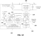
- Fig.12 shows a version of the new input-voltage control scheme for bi-directional ac-dc power converters 100 with both active and reactive power flow control.
- the mains voltage at which this power converter is installed is sensed as a feedback variable (shown in dashed lines). From this sensed voltage signal, the phase angle and/or the frequency of the ac mains voltage can be obtained from circuit 118. The sensed mains voltage is compared with a mains voltage reference in comparator 116.
- the mains voltage reference can be derived with the Droop Characteristic circuit 113 based on the magnitude of the PWM signal (M), the reactive power (Q) and the input current
- the Droop Characteristic circuit can comprise a feedback gain K applied to signal M, and a comparison of that signal to the nominal mains signal in comparator 114 to derive the mains voltage reference
- the difference signal is applied toan error amplifier/compensator 112.
- the output of this circuit is applied to Magnitude and Phase Angle circuit 120.
- a Synchronization circuit 118 receives the mains signal and its output is also applied to circuit 120.
- Circuit 120 generates at least two control variables, namely the magnitude (M) and the phase angle ( ⁇ ) of the PWM, which are applied to the Gate Pattern Generator 110', which in turn drive s the front-stage ac-dc power converter 100, with the objective of controlling the active and reactive power of the bidirectional ac-dc power converter so that the mains voltage Vs will be regulated to a certain mains voltage reference
- the more complex version shown in Fig. 12 includes a control circuit 122 whose output depends on theinput current (Is), angular frequency ( ⁇ s), active power and reactive power
- the output of circuit 122 and the Error Amplifier/Compensator 112 are combined in Real and Reactive Power Computation circuit 124.
- the two outputs of circuit 124 are applied to Magnitude and Phase Angle circuit 120 along with the output of Synchronization circuit 118. The result is the magnitude control signal (M) and the phase angle ( ⁇ ).
- this PWM voltage applied to converter 100 from gate pattern generator 110' is the voltage between points x and y (i.e. V xy ) in Fig 9A .
- M magnitude control signal
- ⁇ phase angle
- the magnitude and phase angle of input current i.e. the input inductor current
- FIG.13 Another input voltage control scheme is shown in Fig.13 .
- this control scheme both the input voltage and the input current (Is) are sensed.
- Information such as input voltage input current (Is), angular frequency phase angle between Vs and Is, active power (P) and reactive power (Q), are thus obtained.
- P and Q the magnitude (M) and angle ( ⁇ ) control signals for the ac-dc power converter 100 can be derived with the objective of regulating the input mains voltage Vs to follow its reference
- Fig.11 and Fig. 12 show two control schemes that generate control signals for the PWM voltage of the bi-directional ac-dc power converter. These two schemes control the input current indirectly, by directly controlling the PWM voltage of the ac-dc power converter.
- Thealternative control scheme as shown in Fig. 13 uses a direct current control.
- the direct current control scheme in Fig.13 is similar to that of the indirect current control schemes in terms of the use of voltage and droop control. However, the magnitude and angle control variables which this scheme generates are for the direct control of the input current.
- the instantaneous input current is sensed in circuit 126 and fed into a current control loop for comparison with the current reference generated at the output of the error circuit 112 by the input voltage control scheme.
- This input current (I f ) is switched and shape d by the bi-directional power converter into the required sinusoidal shape with magnitude and phase angle according to the input voltage control with the objective of regulating the input ac voltage.
- quadrature phase current is compared to in comparator 12S.
- the in-phase current is compared to the reference current from the output of the de voltage control loop in comparator 130.
- the outputs of the comparators 128, 130 are directed to the Current Mode Control 120', which in turn drives the Gate Pattern Generator 110'.
- FIG. 14 An example of the implementation of the input voltage control scheme based on a proportional-integral (PI) compensator is shown in Fig. 14 .
- the input voltage is sampled and applied to both a Root-Mean Square Converter 132 and a Phase-Locked Loop circuit 134.
- Comparators 114 and 116 are used to generate the output e V iin the same way as shown in Fig. 11 , except that one of the inputs to comparator 116 is the output of Root-Mean Square Converter 132 instead of the input voltage Vs.
- the signal e is applied to the Proportional-Integral (PI) compensator 136, whose output is applied to Magnitude Calculation circuit 138.
- PI Proportional-Integral
- circuit 138 does not generate a phase signal, only the magnitude signal M Further, the signal M drives the Sinusoidal Wave Generator 140.
- the output of Phase-Locked Loop circuit 134 is also applied to generator 140, which has an output that drives the PWM generator 142.
- Generator 142 controls the AC-Power Converter 100.
- the input voltage control scheme proposed in this invention does not exclude a control methodology that involves the use of output voltage feedback to assist the proposed input voltage control.
- An example of an implementation of the input voltage control scheme of Fig.11 as represented by the arrangement of Fig. 14 , assisted with the output voltage feedback for the "input voltage control" of the bi-directional power converter, is shown in Fig.15 .
- the output of the Phase-Locked Loop circuit 134 is applied directly to generator 140, it is applied to a comparator 156.
- the de output voltage of the arrangement is compared to a reference in comparator 150.
- the output drives a second PI controller 152, whose output drive s an Angle Calculation circuit 154.
- the output of the Angle Calculation circuit 154 is the se cond input to co mparator 156. It is the output of comparator 156 that drives the Sinusoidal Wave Generator 140 along with the signal M from the Magnitude Calculation circuit 138.
- any reference in this specification to "one embodiment,” “an embodiment,” “exemplary embodiment,” etc., means that a particular feature, structure, or characteristic described in connection with the embodiment is included in at least one embodiment of the invention.
- the appearances of such phrases in various places in the specification are not necessarily all referring to the same embodiment.
Landscapes
- Engineering & Computer Science (AREA)
- Power Engineering (AREA)
- Inverter Devices (AREA)
- Control Of Electrical Variables (AREA)
- Rectifiers (AREA)
Claims (9)
- Vorrichtung, die konfiguriert ist, um Leistungsfluss zwischen einer elektrischen Gleichstromlast und einer Eingangswechselspannungsversorgung des Netzes zu steuern, wobei die Vorrichtung konfiguriert ist, um Wirkleistung und Blindleistung in einer bidirektionalen Weise zu behandeln, wobei die Vorrichtung umfasst:einen Vollbrücken-Leistungsinverter, der als bidirektionaler Wechselstrom-Gleichstrom-Leistungsumrichter (100) angeordnet ist, wobei der Leistungsumrichter netzseitige Wechselstromanschlüsse und lastseitige Gleichstromanschlüsse aufweist, wobei die netzseitigen Wechselstromanschlüsse angeordnet sind, um mit der Eingangswechselspannungsversorgung des Netzes verbunden zu sein;einen Gleichstrom-Stützkondensator, der mit den gleichstromlastseitigen Anschlüssen des Leistungsumrichters (100) parallel verbunden ist, wobei der Gleichstrom-Stützkondensator angeordnet ist, um mit der elektrischen Last parallel verbunden zu sein;ein Mittel der Eingangswechselspannung des Netzes, das umfasst:eine Synchronisationsschaltung (118), die konfiguriert ist, um die Eingangswechselspannung des Netzes, Vs, aufzunehmen;einen Komparator (116), der konfiguriert ist, um die Eingangswechselspannung des Netzes, Vs, mit einer Referenzspannung des Netzes, Vs_ref, zu vergleichen und ein Differenzsignal, eVs, ausgibt;einen Fehlerverstärker/-kompensator (112), der konfiguriert ist, um das Differenzsignal, eVs, aufzunehmen;eine Betrags- und Phasenwinkelschaltung (120), die konfiguriert ist, um Signale auf Grundlage eines Ausgangs von dem Fehlerverstärker/-kompensator (112) und eines Ausgangs von der Synchronisationsschaltung (118) aufzunehmen, wobei die Betrags- und Phasenwinkelschaltung ferner konfiguriert ist, um mindestens zwei Steuervariablen einschließlich eines Betrags, M, und eines Phasenwinkels, σ, für eine Pulsbreitenmodulation, PWM, zu erzeugen;einen Gate-Muster-Generator (110'), der angeordnet ist, um die mindestens zwei Steuergrößen aufzunehmen und die PWM-Spannung zu erzeugen;wobei der Gate-Muster-Generator (110') ferner konfiguriert ist, um den Leistungsumrichter auf Grundlage der PWM-Spannung zu betreiben, um eine Eingangswechselstromgröße des Netzes und einen Eingangswechselstromphasenwinkel des Netzes in Bezug auf die Eingangswechselspannung des Netzes zu steuern, um Schwankungen in der Eingangswechselspannung des Netzes in Bezug auf die Referenzspannung des Netzes zu regulieren.
- Vorrichtung nach Anspruch 1, wobei die Eingangswechselspannungsversorgung des Netzes eine instabile Wechselspannung des Netzes ist, die von einer Wechselstromquelle mit erheblichen intermittierenden erneuerbaren Energiequellen erzeugt wird.
- Vorrichtung nach Anspruch 1, wobei das Steuerungsmittel der Wechselspannung am Netzeingang konfiguriert ist, um Spannungsstärke- und Phasenwinkelsignale für die Steuerung des bidirektionalen Wechselstrom-Gleichstrom-Leistungsumrichters zu erzeugen, wenn Spannungsbetriebsregelung angewendet wird, und Stromstärke- und Phasenwinkelsignale für die Steuerung des bidirektionalen Wechselstrom-Gleichstrom-Leistungsumrichters zu erzeugen, wenn Strombetriebsregelung angewendet wird.
- Vorrichtung nach Anspruch 1, bei das Steuerungsmittel der Wechselspannung am Netzeingang durch einen von verschiedenen Steuerungsansätzen implementiert wird, einschließlich Proportional-Integral-Differential-Verfahren, PID, Verfahren zur Kompensation der Verzögerung und Zustandsraumsteuerung, Gleitmodussteuerung und nichtlineare Grenzsteuerungsverfahren.
- Vorrichtung nach Anspruch 1, ferner einschließend eine Ausgangsspannungs-Rückkopplungsschleife.
- Vorrichtung nach Anspruch 1, wobei ein Spannungsvektor der Eingangswechselspannung des Netzes und ein Stromvektor des Eingangswechselstroms des Netzes, die von dem bidirektionalen Wechselstrom-Gleichstrom-Leistungsumrichter erzeugt werden, in der Lage sind, von 90 Grad abzuweichen, um Wirkleistung zu verarbeiten.
- Vorrichtung nach Anspruch 1, wobei die elektrische Gleichstromlast mindestens ein Energiespeicherelement oder eine Energiequelle enthält, und die Vorrichtung konfiguriert ist, um Wirk- und Blindleistung von der elektrischen Gleichstromlast zurück an die Eingangswechselspannungsversorgung zu übertragen, um die Eingangswechselspannung des Netzes der Eingangswechselspannungsversorgung zu regeln.
- Vorrichtung nach Anspruch 1, wobei die Steuerung der Eingangswechselspannung des Netzes konfiguriert ist, um in einem Regelkreis DROOP-Regelverfahren zu verwenden.
- Vorrichtung nach Anspruch 1, wobei das Steuerungsmittel für die Eingangswechselspannung des Netzes Phasenverschiebungssteuerung und pulsbreitenmodulierte Schaltverfahren einschließen.
Applications Claiming Priority (2)
| Application Number | Priority Date | Filing Date | Title |
|---|---|---|---|
| US201261654628P | 2012-06-01 | 2012-06-01 | |
| PCT/CN2013/076330 WO2013178054A1 (en) | 2012-06-01 | 2013-05-28 | Input ac voltage control bi-directional power converters |
Publications (3)
| Publication Number | Publication Date |
|---|---|
| EP2856598A1 EP2856598A1 (de) | 2015-04-08 |
| EP2856598A4 EP2856598A4 (de) | 2016-03-09 |
| EP2856598B1 true EP2856598B1 (de) | 2023-07-19 |
Family
ID=49670065
Family Applications (1)
| Application Number | Title | Priority Date | Filing Date |
|---|---|---|---|
| EP13797168.5A Active EP2856598B1 (de) | 2012-06-01 | 2013-05-28 | Bidirektionale leistungswandler mit steuerung der eingangswechselspannung |
Country Status (4)
| Country | Link |
|---|---|
| US (1) | US20130322139A1 (de) |
| EP (1) | EP2856598B1 (de) |
| CN (1) | CN104471816B (de) |
| WO (1) | WO2013178054A1 (de) |
Families Citing this family (37)
| Publication number | Priority date | Publication date | Assignee | Title |
|---|---|---|---|---|
| FR2991826B1 (fr) * | 2012-06-07 | 2015-03-27 | Intelligent Electronic Systems | Dispositif de charge a entree adaptative |
| US10782721B2 (en) * | 2012-08-27 | 2020-09-22 | Stem, Inc. | Method and apparatus for balancing power on a per phase basis in multi-phase electrical load facilities using an energy storage system |
| US9548794B2 (en) | 2013-05-03 | 2017-01-17 | Cooper Technologies Company | Power factor correction for constant current input with power line communication |
| US9190901B2 (en) | 2013-05-03 | 2015-11-17 | Cooper Technologies Company | Bridgeless boost power factor correction circuit for constant current input |
| US9000736B2 (en) * | 2013-05-03 | 2015-04-07 | Cooper Technologies Company | Power factor correction algorithm for arbitrary input waveform |
| US9214855B2 (en) | 2013-05-03 | 2015-12-15 | Cooper Technologies Company | Active power factor correction circuit for a constant current power converter |
| CN112103967B (zh) * | 2013-07-09 | 2024-07-09 | 香港大学 | 自适应ac和/或dc电源 |
| EP3031121A4 (de) | 2013-08-06 | 2017-02-15 | Bedrock Automation Platforms Inc. | Intelligentes energiesystem |
| US9748781B2 (en) * | 2014-06-24 | 2017-08-29 | Intersil Americas LLC | Voltage converters and methods for use therewith |
| CN107005049B (zh) * | 2014-11-13 | 2020-12-01 | 香港大学 | 功率控制器和功率控制方法 |
| WO2016126263A1 (en) * | 2015-02-06 | 2016-08-11 | United Technologies Corporation | Grid connected and islanded modes seamless transition |
| WO2016134319A1 (en) * | 2015-02-19 | 2016-08-25 | Enphase Energy, Inc. | Method and apparatus for time-domain droop control with integrated phasor current control |
| CN104779607B (zh) * | 2015-04-27 | 2017-03-01 | 重庆大学 | 直流微网中的一种分布式协调控制方法及系统 |
| US10858911B2 (en) | 2015-09-04 | 2020-12-08 | Baker Hughes, A Ge Company, Llc | Bidirectional chopping of high voltage power in high temperature downhole tools to reduce tool size |
| WO2017125067A1 (en) | 2016-01-22 | 2017-07-27 | The University Of Hong Kong | Power supply supporting virtual inertia for grid control (micro-spring converter) |
| US10027119B2 (en) * | 2016-05-28 | 2018-07-17 | PXiSE Energy Solutions, LLC | Decoupling synchrophasor based control system for multiple distributed energy resources |
| US10615604B2 (en) * | 2016-05-28 | 2020-04-07 | PXiSE Energy Solutions, LLC | Decoupling synchrophasor based control system for distributed energy resources |
| CN106249586B (zh) * | 2016-07-15 | 2019-04-02 | 华北水利水电大学 | 一种支持单相和三相电压跟踪的锁相环方法 |
| CN106532716B (zh) * | 2016-10-28 | 2020-03-10 | 广东电网有限责任公司电力科学研究院 | 一种智能负荷调节电路及控制系统 |
| CN107086786B (zh) * | 2017-04-11 | 2019-06-11 | 天津大学 | 双向能量流动的交互式稳压系统及操作方法 |
| CN107437899B (zh) * | 2017-09-13 | 2019-08-23 | 上海交通大学 | 网流正弦的单相ac-dc变换电路 |
| CN109031000B (zh) * | 2018-08-03 | 2019-08-16 | 贵州电网有限责任公司电网规划研究中心 | 一种基于非故障扰动就地测量电网短路容量的方法及系统 |
| CN110048405B (zh) * | 2019-04-03 | 2023-03-28 | 上海交通大学 | 基于电力弹簧的微电网能量优化方法 |
| TWI678607B (zh) * | 2019-04-10 | 2019-12-01 | 群光電能科技股份有限公司 | 圖騰柱無橋功率因數轉換裝置及其操作方法 |
| CN110148966B (zh) * | 2019-05-28 | 2023-04-28 | 内蒙古电力(集团)有限责任公司内蒙古电力科学研究院分公司 | 基于并联双逆变器的并离网控制方法及装置 |
| EP3876676A1 (de) * | 2020-03-03 | 2021-09-08 | Signify Holding B.V. | Treiber zum antrieb einer last sowie eine entsprechende led-basierte beleuchtungsvorrichtung und entsprechendes verfahren zum betrieb des treibers |
| CN112202185B (zh) * | 2020-10-16 | 2022-10-04 | 安徽大学 | 基于李雅普诺夫函数的大功率电源系统的svc控制方法 |
| CN121546532A (zh) * | 2020-10-16 | 2026-02-17 | 日立能源有限公司 | 电力网 |
| CN112688350A (zh) * | 2020-12-21 | 2021-04-20 | 南京工程学院 | 基于分数阶微积分控制的电力弹簧调压策略、系统及配电网 |
| US11056912B1 (en) | 2021-01-25 | 2021-07-06 | PXiSE Energy Solutions, LLC | Power system optimization using hierarchical clusters |
| CN113206521B (zh) * | 2021-04-02 | 2023-01-31 | Oppo广东移动通信有限公司 | 功率控制方法、装置、电子设备及存储介质 |
| EP4360182A4 (de) * | 2021-06-23 | 2025-05-21 | Nanyang Technological University | System und verfahren zur stabilisierung eines stromverteilungsnetzes |
| CN114256830B (zh) * | 2021-12-15 | 2022-10-11 | 天津大学 | 基于等值单台变换器的直流系统控制参数整定方法 |
| US11757371B1 (en) * | 2022-08-02 | 2023-09-12 | Rivian Ip Holdings, Llc | Pulse-width modulation for high-efficiency power conversion |
| CN116581810B (zh) * | 2022-09-21 | 2024-10-22 | 华中科技大学 | 一种提高下垂控制构网型并网逆变器暂态稳定性的控制方法及并网逆变器 |
| CN115566723B (zh) * | 2022-10-18 | 2025-06-27 | 哈尔滨工业大学 | 基于电力弹簧的交直流微网互联变换器单位功率因数控制方法 |
| CN116073687B (zh) * | 2023-03-01 | 2023-06-09 | 山东艾诺智能仪器有限公司 | 一种带模拟控制环路的宽频带逆变电源 |
Citations (2)
| Publication number | Priority date | Publication date | Assignee | Title |
|---|---|---|---|---|
| EP0085249B1 (de) * | 1981-12-21 | 1986-05-21 | Helionetics, Inc. | Verfahren und Gerät zur Umformung elektrischer Leistung |
| WO1996018937A1 (en) * | 1994-12-14 | 1996-06-20 | Kenetech Windpower, Inc. | Grid connected bi-directional converter including a pwm, dc-dc chopper, and energy storage/supply device |
Family Cites Families (38)
| Publication number | Priority date | Publication date | Assignee | Title |
|---|---|---|---|---|
| US4891744A (en) * | 1987-11-20 | 1990-01-02 | Mitsubishi Denki Kaubshiki Kaisha | Power converter control circuit |
| CA1313219C (en) * | 1988-10-07 | 1993-01-26 | Boon-Teck Ooi | Pulse width modulation high voltage direct current transmission system and converter |
| US5091840A (en) * | 1990-08-14 | 1992-02-25 | General Electric Company | Power conversion scheme employing shorting means to control current magnitude |
| US5083039B1 (en) * | 1991-02-01 | 1999-11-16 | Zond Energy Systems Inc | Variable speed wind turbine |
| JPH05300674A (ja) * | 1992-04-23 | 1993-11-12 | Hitachi Ltd | 超電導エネルギー貯蔵装置および超電導エネルギー貯蔵装置の制御方法 |
| JP4585774B2 (ja) * | 2003-03-07 | 2010-11-24 | キヤノン株式会社 | 電力変換装置および電源装置 |
| GB2405540B (en) * | 2003-08-27 | 2006-05-10 | Ron Shu-Yuen Hui | Apparatus and method for providing dimming control of lamps and electrical lighting systems |
| US20060092588A1 (en) * | 2004-10-28 | 2006-05-04 | Realmuto Richard A | Multiple bi-directional input/output power control system |
| FI121491B (fi) * | 2004-11-11 | 2010-11-30 | Vacon Oyj | Taajuusmuuttajan ylijännitesuojaus |
| JP4399405B2 (ja) * | 2005-08-25 | 2010-01-13 | 株式会社MERSTech | 進相電流による交流電圧制御装置 |
| US7511385B2 (en) * | 2005-11-11 | 2009-03-31 | Converteam Ltd | Power converters |
| WO2008077974A1 (es) * | 2006-12-22 | 2008-07-03 | Wind To Power System, S.L. | Generador asíncrono de doble alimentación |
| WO2008137836A1 (en) * | 2007-05-04 | 2008-11-13 | The University Of Alabama | Converter control of variable-speed wind turbines |
| KR100886194B1 (ko) * | 2007-06-08 | 2009-02-27 | 한국전기연구원 | 계통 연계형 고압 권선형 유도 발전기 제어 장치 |
| WO2009153360A1 (es) * | 2008-06-17 | 2009-12-23 | Ingeteam Energy, S.A. | Metodo de control para estructura de conversion de corriente continua a corriente alterna |
| JP5809558B2 (ja) * | 2008-06-27 | 2015-11-11 | ザ リージェンツ オブ ザ ユニバーシティ オブ カリフォルニア | 荷電粒子ビームからの直接エネルギー抽出のための回路 |
| CN102197583B (zh) * | 2008-08-29 | 2014-07-30 | 维斯塔斯风力系统集团公司 | 用于控制ac发电机的方法和控制设备 |
| US8334616B2 (en) * | 2008-09-19 | 2012-12-18 | Electric Power Research Institute, Inc. | Photovoltaic integrated variable frequency drive |
| WO2010114792A1 (en) * | 2009-04-01 | 2010-10-07 | The Board Of Trustees Of The University Of Alabama | Intelligent power converter control for grid integration of renewable energies |
| JP4783453B2 (ja) * | 2009-09-10 | 2011-09-28 | 力也 阿部 | 多端子型非同期連系装置、電力機器制御端末装置と電力ネットワークシステムおよびその制御方法 |
| US8860236B2 (en) * | 2009-10-19 | 2014-10-14 | Uwm Research Foundation, Inc. | Wind energy power conversion system reducing gearbox stress and improving power stability |
| CN101710704A (zh) * | 2009-12-17 | 2010-05-19 | 清华大学 | 用于高压系统的有功功率和无功功率调节的电能调节装置 |
| JP5320311B2 (ja) * | 2010-01-18 | 2013-10-23 | 三菱重工業株式会社 | 可変速発電装置及びその制御方法 |
| US8432052B2 (en) * | 2010-05-27 | 2013-04-30 | Rockwell Automation Technologies, Inc. | Wind power converter system with grid side reactive power control |
| US9391554B2 (en) * | 2010-08-25 | 2016-07-12 | University Of Alabama | Control of a permanent magnet synchronous generator wind turbine |
| EP3573208B1 (de) * | 2010-10-04 | 2024-10-23 | Versitech, Ltd. | Leistungsregelschaltung und verfahren zur stabilisierung einer stromversorgung |
| CN202068223U (zh) * | 2011-03-01 | 2011-12-07 | 东南大学 | 一种基于v2g技术的车载充放电装置 |
| RU2576021C2 (ru) * | 2011-03-11 | 2016-02-27 | Сименс Акциенгезелльшафт | Возбудитель блока генерирования мощности, блок генерирования мощности и оборудование вывода энергии в электрической сети |
| US8922062B2 (en) * | 2011-03-14 | 2014-12-30 | Sunpower Corporation | Automatic voltage regulation for photovoltaic systems |
| US9071141B2 (en) * | 2011-04-08 | 2015-06-30 | Virginia Tech Intellectual Properties, Inc. | Two-stage single phase bi-directional PWM power converter with DC link capacitor reduction |
| US20120290145A1 (en) * | 2011-05-10 | 2012-11-15 | Madhuwanti Joshi | Single-stage grid-connected solar inverter for distributed reactive power generation |
| US9281756B2 (en) * | 2011-11-11 | 2016-03-08 | Varentec, Inc. | Power flow controller with a fractionally rated back-to-back converter |
| WO2013087085A1 (en) * | 2011-12-16 | 2013-06-20 | Fachhochschule Südwestfalen | Method for active control of frequency and voltage in a power supply grid with decentralized power supply systems |
| US8890364B2 (en) * | 2011-12-21 | 2014-11-18 | General Electric Company | Methods and systems for controlling an intra-plant voltage level |
| US9065321B2 (en) * | 2011-12-22 | 2015-06-23 | Varentec, Inc. | Isolated dynamic current converters |
| US9046077B2 (en) * | 2011-12-28 | 2015-06-02 | General Electric Company | Reactive power controller for controlling reactive power in a wind farm |
| WO2013134573A1 (en) * | 2012-03-08 | 2013-09-12 | Massachusetts Institute Of Technology | Resonant power converters using impedance control networks and related techniques |
| EP2793392B1 (de) * | 2013-04-16 | 2023-07-12 | Siemens Aktiengesellschaft | Steuergerät zur Steuerung eines Stromwandlers |
-
2013
- 2013-05-28 WO PCT/CN2013/076330 patent/WO2013178054A1/en not_active Ceased
- 2013-05-28 EP EP13797168.5A patent/EP2856598B1/de active Active
- 2013-05-28 CN CN201380028775.3A patent/CN104471816B/zh active Active
- 2013-05-31 US US13/907,350 patent/US20130322139A1/en not_active Abandoned
Patent Citations (2)
| Publication number | Priority date | Publication date | Assignee | Title |
|---|---|---|---|---|
| EP0085249B1 (de) * | 1981-12-21 | 1986-05-21 | Helionetics, Inc. | Verfahren und Gerät zur Umformung elektrischer Leistung |
| WO1996018937A1 (en) * | 1994-12-14 | 1996-06-20 | Kenetech Windpower, Inc. | Grid connected bi-directional converter including a pwm, dc-dc chopper, and energy storage/supply device |
Also Published As
| Publication number | Publication date |
|---|---|
| WO2013178054A1 (en) | 2013-12-05 |
| EP2856598A4 (de) | 2016-03-09 |
| HK1208566A1 (en) | 2016-03-04 |
| EP2856598A1 (de) | 2015-04-08 |
| US20130322139A1 (en) | 2013-12-05 |
| CN104471816A (zh) | 2015-03-25 |
| CN104471816B (zh) | 2019-01-15 |
Similar Documents
| Publication | Publication Date | Title |
|---|---|---|
| EP2856598B1 (de) | Bidirektionale leistungswandler mit steuerung der eingangswechselspannung | |
| Pena-Alzola et al. | Control design of a PFC with harmonic mitigation function for small hybrid AC/DC buildings | |
| Ghodke et al. | One-cycle-controlled bidirectional AC-to-DC converter with constant power factor | |
| CN101185044A (zh) | 功率因数校正的数字实现 | |
| Umamaheswari et al. | Analysis and design of reduced order linear quadratic regulator control for three phase power factor correction using Cuk rectifiers | |
| CN102751913B (zh) | 使用太阳能电池的发电系统 | |
| US12294295B2 (en) | Systems and methods of unwanted harmonic content removal for power conversion | |
| Parthiban et al. | Experimental validation of solar PV sustained ZSI based unified active power filter for enrichment of power quality | |
| Ray et al. | Integrated hybrid output converter as power router for renewable-based nanogrids | |
| Lee et al. | Mitigation of low frequency ac ripple in single-phase photovoltaic power conditioning systems | |
| Kadu et al. | Application of STATCOM for harmonic mitigation and power factor improvement using direct current control technique | |
| Zhang et al. | Autonomous control strategy of bidirectional AC/DC converter in low voltage hybrid microgrid | |
| Kim et al. | High-performance line conditioner with output voltage regulation and power factor correction | |
| CN115413360A (zh) | 用于光伏能源的电力转换器 | |
| Kotturu et al. | Simplified predictive control of unified power quality conditioner | |
| Gaiceanu | for Renewable Energy Sources Integration | |
| Li et al. | Grid voltage modulated control of grid-connected voltage source inverters under unbalanced grid conditions | |
| CN113872209A (zh) | 一种消除直流母线电压采样纹波的单相光伏并网控制方法 | |
| Femia et al. | Dynamic model of a grid-connected photovoltaic inverter with one cycle control | |
| Kato et al. | Instantaneous Load Voltage Control for Three-phase to Single-phase Matrix Converter | |
| CN104734323B (zh) | 混合供电系统及其供电方法和电器设备 | |
| Shanthi et al. | Analysis of predictive control algorithm based PWM boost converter-based hybrid networks | |
| Meraj et al. | Virtual flux oriented sensorless direct power control of qzs inverter connected to grid for solar pv applications | |
| HK1208566B (zh) | 输入ac电压控制双向功率转换器 | |
| Varghese et al. | Analysis and Design of PFC with SEPIC Converter: A PQ Theory-Based Current Generation Approach |
Legal Events
| Date | Code | Title | Description |
|---|---|---|---|
| PUAI | Public reference made under article 153(3) epc to a published international application that has entered the european phase |
Free format text: ORIGINAL CODE: 0009012 |
|
| 17P | Request for examination filed |
Effective date: 20141125 |
|
| AK | Designated contracting states |
Kind code of ref document: A1 Designated state(s): AL AT BE BG CH CY CZ DE DK EE ES FI FR GB GR HR HU IE IS IT LI LT LU LV MC MK MT NL NO PL PT RO RS SE SI SK SM TR |
|
| AX | Request for extension of the european patent |
Extension state: BA ME |
|
| DAX | Request for extension of the european patent (deleted) | ||
| RA4 | Supplementary search report drawn up and despatched (corrected) |
Effective date: 20160208 |
|
| RIC1 | Information provided on ipc code assigned before grant |
Ipc: H02J 3/18 20060101ALI20160202BHEP Ipc: H02M 7/797 20060101ALI20160202BHEP Ipc: H02M 7/219 20060101ALI20160202BHEP Ipc: H02J 3/38 20060101ALI20160202BHEP Ipc: H02J 3/12 20060101AFI20160202BHEP |
|
| STAA | Information on the status of an ep patent application or granted ep patent |
Free format text: STATUS: EXAMINATION IS IN PROGRESS |
|
| 17Q | First examination report despatched |
Effective date: 20190104 |
|
| REG | Reference to a national code |
Ref country code: DE Ref legal event code: R079 Ref document number: 602013084267 Country of ref document: DE Free format text: PREVIOUS MAIN CLASS: H02J0003120000 Ipc: H02J0003180000 Ref country code: DE Ref legal event code: R079 Free format text: PREVIOUS MAIN CLASS: H02J0003120000 Ipc: H02J0003180000 |
|
| GRAP | Despatch of communication of intention to grant a patent |
Free format text: ORIGINAL CODE: EPIDOSNIGR1 |
|
| STAA | Information on the status of an ep patent application or granted ep patent |
Free format text: STATUS: GRANT OF PATENT IS INTENDED |
|
| INTG | Intention to grant announced |
Effective date: 20230317 |
|
| RIC1 | Information provided on ipc code assigned before grant |
Ipc: H02J 3/38 20060101ALN20230303BHEP Ipc: H02M 7/797 20060101ALI20230303BHEP Ipc: H02M 7/219 20060101ALI20230303BHEP Ipc: H02J 3/44 20060101ALI20230303BHEP Ipc: H02J 3/18 20060101AFI20230303BHEP |
|
| GRAS | Grant fee paid |
Free format text: ORIGINAL CODE: EPIDOSNIGR3 |
|
| GRAA | (expected) grant |
Free format text: ORIGINAL CODE: 0009210 |
|
| STAA | Information on the status of an ep patent application or granted ep patent |
Free format text: STATUS: THE PATENT HAS BEEN GRANTED |
|
| AK | Designated contracting states |
Kind code of ref document: B1 Designated state(s): AL AT BE BG CH CY CZ DE DK EE ES FI FR GB GR HR HU IE IS IT LI LT LU LV MC MK MT NL NO PL PT RO RS SE SI SK SM TR |
|
| REG | Reference to a national code |
Ref country code: GB Ref legal event code: FG4D |
|
| REG | Reference to a national code |
Ref country code: CH Ref legal event code: EP |
|
| REG | Reference to a national code |
Ref country code: DE Ref legal event code: R096 Ref document number: 602013084267 Country of ref document: DE |
|
| REG | Reference to a national code |
Ref country code: IE Ref legal event code: FG4D |
|
| REG | Reference to a national code |
Ref country code: LT Ref legal event code: MG9D |
|
| REG | Reference to a national code |
Ref country code: NL Ref legal event code: MP Effective date: 20230719 |
|
| REG | Reference to a national code |
Ref country code: AT Ref legal event code: MK05 Ref document number: 1590458 Country of ref document: AT Kind code of ref document: T Effective date: 20230719 |
|
| PG25 | Lapsed in a contracting state [announced via postgrant information from national office to epo] |
Ref country code: NL Free format text: LAPSE BECAUSE OF FAILURE TO SUBMIT A TRANSLATION OF THE DESCRIPTION OR TO PAY THE FEE WITHIN THE PRESCRIBED TIME-LIMIT Effective date: 20230719 |
|
| PG25 | Lapsed in a contracting state [announced via postgrant information from national office to epo] |
Ref country code: GR Free format text: LAPSE BECAUSE OF FAILURE TO SUBMIT A TRANSLATION OF THE DESCRIPTION OR TO PAY THE FEE WITHIN THE PRESCRIBED TIME-LIMIT Effective date: 20231020 |
|
| PG25 | Lapsed in a contracting state [announced via postgrant information from national office to epo] |
Ref country code: IS Free format text: LAPSE BECAUSE OF FAILURE TO SUBMIT A TRANSLATION OF THE DESCRIPTION OR TO PAY THE FEE WITHIN THE PRESCRIBED TIME-LIMIT Effective date: 20231119 |
|
| PG25 | Lapsed in a contracting state [announced via postgrant information from national office to epo] |
Ref country code: SE Free format text: LAPSE BECAUSE OF FAILURE TO SUBMIT A TRANSLATION OF THE DESCRIPTION OR TO PAY THE FEE WITHIN THE PRESCRIBED TIME-LIMIT Effective date: 20230719 Ref country code: RS Free format text: LAPSE BECAUSE OF FAILURE TO SUBMIT A TRANSLATION OF THE DESCRIPTION OR TO PAY THE FEE WITHIN THE PRESCRIBED TIME-LIMIT Effective date: 20230719 Ref country code: PT Free format text: LAPSE BECAUSE OF FAILURE TO SUBMIT A TRANSLATION OF THE DESCRIPTION OR TO PAY THE FEE WITHIN THE PRESCRIBED TIME-LIMIT Effective date: 20231120 Ref country code: NO Free format text: LAPSE BECAUSE OF FAILURE TO SUBMIT A TRANSLATION OF THE DESCRIPTION OR TO PAY THE FEE WITHIN THE PRESCRIBED TIME-LIMIT Effective date: 20231019 Ref country code: LV Free format text: LAPSE BECAUSE OF FAILURE TO SUBMIT A TRANSLATION OF THE DESCRIPTION OR TO PAY THE FEE WITHIN THE PRESCRIBED TIME-LIMIT Effective date: 20230719 Ref country code: LT Free format text: LAPSE BECAUSE OF FAILURE TO SUBMIT A TRANSLATION OF THE DESCRIPTION OR TO PAY THE FEE WITHIN THE PRESCRIBED TIME-LIMIT Effective date: 20230719 Ref country code: IS Free format text: LAPSE BECAUSE OF FAILURE TO SUBMIT A TRANSLATION OF THE DESCRIPTION OR TO PAY THE FEE WITHIN THE PRESCRIBED TIME-LIMIT Effective date: 20231119 Ref country code: HR Free format text: LAPSE BECAUSE OF FAILURE TO SUBMIT A TRANSLATION OF THE DESCRIPTION OR TO PAY THE FEE WITHIN THE PRESCRIBED TIME-LIMIT Effective date: 20230719 Ref country code: GR Free format text: LAPSE BECAUSE OF FAILURE TO SUBMIT A TRANSLATION OF THE DESCRIPTION OR TO PAY THE FEE WITHIN THE PRESCRIBED TIME-LIMIT Effective date: 20231020 Ref country code: FI Free format text: LAPSE BECAUSE OF FAILURE TO SUBMIT A TRANSLATION OF THE DESCRIPTION OR TO PAY THE FEE WITHIN THE PRESCRIBED TIME-LIMIT Effective date: 20230719 Ref country code: AT Free format text: LAPSE BECAUSE OF FAILURE TO SUBMIT A TRANSLATION OF THE DESCRIPTION OR TO PAY THE FEE WITHIN THE PRESCRIBED TIME-LIMIT Effective date: 20230719 |
|
| PG25 | Lapsed in a contracting state [announced via postgrant information from national office to epo] |
Ref country code: PL Free format text: LAPSE BECAUSE OF FAILURE TO SUBMIT A TRANSLATION OF THE DESCRIPTION OR TO PAY THE FEE WITHIN THE PRESCRIBED TIME-LIMIT Effective date: 20230719 |
|
| REG | Reference to a national code |
Ref country code: DE Ref legal event code: R097 Ref document number: 602013084267 Country of ref document: DE |
|
| PG25 | Lapsed in a contracting state [announced via postgrant information from national office to epo] |
Ref country code: ES Free format text: LAPSE BECAUSE OF FAILURE TO SUBMIT A TRANSLATION OF THE DESCRIPTION OR TO PAY THE FEE WITHIN THE PRESCRIBED TIME-LIMIT Effective date: 20230719 |
|
| PG25 | Lapsed in a contracting state [announced via postgrant information from national office to epo] |
Ref country code: SM Free format text: LAPSE BECAUSE OF FAILURE TO SUBMIT A TRANSLATION OF THE DESCRIPTION OR TO PAY THE FEE WITHIN THE PRESCRIBED TIME-LIMIT Effective date: 20230719 Ref country code: RO Free format text: LAPSE BECAUSE OF FAILURE TO SUBMIT A TRANSLATION OF THE DESCRIPTION OR TO PAY THE FEE WITHIN THE PRESCRIBED TIME-LIMIT Effective date: 20230719 Ref country code: ES Free format text: LAPSE BECAUSE OF FAILURE TO SUBMIT A TRANSLATION OF THE DESCRIPTION OR TO PAY THE FEE WITHIN THE PRESCRIBED TIME-LIMIT Effective date: 20230719 Ref country code: EE Free format text: LAPSE BECAUSE OF FAILURE TO SUBMIT A TRANSLATION OF THE DESCRIPTION OR TO PAY THE FEE WITHIN THE PRESCRIBED TIME-LIMIT Effective date: 20230719 Ref country code: DK Free format text: LAPSE BECAUSE OF FAILURE TO SUBMIT A TRANSLATION OF THE DESCRIPTION OR TO PAY THE FEE WITHIN THE PRESCRIBED TIME-LIMIT Effective date: 20230719 Ref country code: CZ Free format text: LAPSE BECAUSE OF FAILURE TO SUBMIT A TRANSLATION OF THE DESCRIPTION OR TO PAY THE FEE WITHIN THE PRESCRIBED TIME-LIMIT Effective date: 20230719 Ref country code: SK Free format text: LAPSE BECAUSE OF FAILURE TO SUBMIT A TRANSLATION OF THE DESCRIPTION OR TO PAY THE FEE WITHIN THE PRESCRIBED TIME-LIMIT Effective date: 20230719 |
|
| PLBE | No opposition filed within time limit |
Free format text: ORIGINAL CODE: 0009261 |
|
| STAA | Information on the status of an ep patent application or granted ep patent |
Free format text: STATUS: NO OPPOSITION FILED WITHIN TIME LIMIT |
|
| PG25 | Lapsed in a contracting state [announced via postgrant information from national office to epo] |
Ref country code: IT Free format text: LAPSE BECAUSE OF FAILURE TO SUBMIT A TRANSLATION OF THE DESCRIPTION OR TO PAY THE FEE WITHIN THE PRESCRIBED TIME-LIMIT Effective date: 20230719 |
|
| 26N | No opposition filed |
Effective date: 20240422 |
|
| PG25 | Lapsed in a contracting state [announced via postgrant information from national office to epo] |
Ref country code: SI Free format text: LAPSE BECAUSE OF FAILURE TO SUBMIT A TRANSLATION OF THE DESCRIPTION OR TO PAY THE FEE WITHIN THE PRESCRIBED TIME-LIMIT Effective date: 20230719 |
|
| PG25 | Lapsed in a contracting state [announced via postgrant information from national office to epo] |
Ref country code: BG Free format text: LAPSE BECAUSE OF FAILURE TO SUBMIT A TRANSLATION OF THE DESCRIPTION OR TO PAY THE FEE WITHIN THE PRESCRIBED TIME-LIMIT Effective date: 20230719 |
|
| PG25 | Lapsed in a contracting state [announced via postgrant information from national office to epo] |
Ref country code: BG Free format text: LAPSE BECAUSE OF FAILURE TO SUBMIT A TRANSLATION OF THE DESCRIPTION OR TO PAY THE FEE WITHIN THE PRESCRIBED TIME-LIMIT Effective date: 20230719 |
|
| REG | Reference to a national code |
Ref country code: CH Ref legal event code: PL |
|
| PG25 | Lapsed in a contracting state [announced via postgrant information from national office to epo] |
Ref country code: MC Free format text: LAPSE BECAUSE OF FAILURE TO SUBMIT A TRANSLATION OF THE DESCRIPTION OR TO PAY THE FEE WITHIN THE PRESCRIBED TIME-LIMIT Effective date: 20230719 |
|
| PG25 | Lapsed in a contracting state [announced via postgrant information from national office to epo] |
Ref country code: LU Free format text: LAPSE BECAUSE OF NON-PAYMENT OF DUE FEES Effective date: 20240528 |
|
| PG25 | Lapsed in a contracting state [announced via postgrant information from national office to epo] |
Ref country code: MC Free format text: LAPSE BECAUSE OF FAILURE TO SUBMIT A TRANSLATION OF THE DESCRIPTION OR TO PAY THE FEE WITHIN THE PRESCRIBED TIME-LIMIT Effective date: 20230719 Ref country code: LU Free format text: LAPSE BECAUSE OF NON-PAYMENT OF DUE FEES Effective date: 20240528 Ref country code: CH Free format text: LAPSE BECAUSE OF NON-PAYMENT OF DUE FEES Effective date: 20240531 |
|
| REG | Reference to a national code |
Ref country code: BE Ref legal event code: MM Effective date: 20240531 |
|
| PG25 | Lapsed in a contracting state [announced via postgrant information from national office to epo] |
Ref country code: IE Free format text: LAPSE BECAUSE OF NON-PAYMENT OF DUE FEES Effective date: 20240528 |
|
| PG25 | Lapsed in a contracting state [announced via postgrant information from national office to epo] |
Ref country code: BE Free format text: LAPSE BECAUSE OF NON-PAYMENT OF DUE FEES Effective date: 20240531 |
|
| PGFP | Annual fee paid to national office [announced via postgrant information from national office to epo] |
Ref country code: DE Payment date: 20250402 Year of fee payment: 13 |
|
| PGFP | Annual fee paid to national office [announced via postgrant information from national office to epo] |
Ref country code: GB Payment date: 20250401 Year of fee payment: 13 |
|
| PGFP | Annual fee paid to national office [announced via postgrant information from national office to epo] |
Ref country code: FR Payment date: 20250401 Year of fee payment: 13 |
|
| PG25 | Lapsed in a contracting state [announced via postgrant information from national office to epo] |
Ref country code: CY Free format text: LAPSE BECAUSE OF FAILURE TO SUBMIT A TRANSLATION OF THE DESCRIPTION OR TO PAY THE FEE WITHIN THE PRESCRIBED TIME-LIMIT; INVALID AB INITIO Effective date: 20130528 |
|
| PG25 | Lapsed in a contracting state [announced via postgrant information from national office to epo] |
Ref country code: HU Free format text: LAPSE BECAUSE OF FAILURE TO SUBMIT A TRANSLATION OF THE DESCRIPTION OR TO PAY THE FEE WITHIN THE PRESCRIBED TIME-LIMIT; INVALID AB INITIO Effective date: 20130528 |