EP2857113A1 - Procédé destiné au nettoyage d'une surface d'un espace creux - Google Patents
Procédé destiné au nettoyage d'une surface d'un espace creux Download PDFInfo
- Publication number
- EP2857113A1 EP2857113A1 EP20140184720 EP14184720A EP2857113A1 EP 2857113 A1 EP2857113 A1 EP 2857113A1 EP 20140184720 EP20140184720 EP 20140184720 EP 14184720 A EP14184720 A EP 14184720A EP 2857113 A1 EP2857113 A1 EP 2857113A1
- Authority
- EP
- European Patent Office
- Prior art keywords
- process head
- axis
- symmetry
- tire
- distance
- Prior art date
- Legal status (The legal status is an assumption and is not a legal conclusion. Google has not performed a legal analysis and makes no representation as to the accuracy of the status listed.)
- Withdrawn
Links
- 238000000034 method Methods 0.000 title claims abstract description 94
- 238000004140 cleaning Methods 0.000 title claims abstract description 38
- 238000005259 measurement Methods 0.000 description 18
- VYPSYNLAJGMNEJ-UHFFFAOYSA-N Silicium dioxide Chemical compound O=[Si]=O VYPSYNLAJGMNEJ-UHFFFAOYSA-N 0.000 description 3
- 238000004519 manufacturing process Methods 0.000 description 2
- CURLTUGMZLYLDI-UHFFFAOYSA-N Carbon dioxide Chemical compound O=C=O CURLTUGMZLYLDI-UHFFFAOYSA-N 0.000 description 1
- 244000089486 Phragmites australis subsp australis Species 0.000 description 1
- NINIDFKCEFEMDL-UHFFFAOYSA-N Sulfur Chemical compound [S] NINIDFKCEFEMDL-UHFFFAOYSA-N 0.000 description 1
- 239000006229 carbon black Substances 0.000 description 1
- 235000011089 carbon dioxide Nutrition 0.000 description 1
- 238000010276 construction Methods 0.000 description 1
- 238000006073 displacement reaction Methods 0.000 description 1
- 230000000694 effects Effects 0.000 description 1
- 238000010438 heat treatment Methods 0.000 description 1
- 239000000463 material Substances 0.000 description 1
- 239000000203 mixture Substances 0.000 description 1
- 239000005060 rubber Substances 0.000 description 1
- 239000004576 sand Substances 0.000 description 1
- 238000007493 shaping process Methods 0.000 description 1
- 239000000377 silicon dioxide Substances 0.000 description 1
- 239000007787 solid Substances 0.000 description 1
- 229910052717 sulfur Inorganic materials 0.000 description 1
- 239000011593 sulfur Substances 0.000 description 1
Images


Classifications
-
- B—PERFORMING OPERATIONS; TRANSPORTING
- B29—WORKING OF PLASTICS; WORKING OF SUBSTANCES IN A PLASTIC STATE IN GENERAL
- B29D—PRODUCING PARTICULAR ARTICLES FROM PLASTICS OR FROM SUBSTANCES IN A PLASTIC STATE
- B29D30/00—Producing pneumatic or solid tyres or parts thereof
- B29D30/06—Pneumatic tyres or parts thereof (e.g. produced by casting, moulding, compression moulding, injection moulding, centrifugal casting)
- B29D30/0601—Vulcanising tyres; Vulcanising presses for tyres
- B29D30/0662—Accessories, details or auxiliary operations
-
- B—PERFORMING OPERATIONS; TRANSPORTING
- B29—WORKING OF PLASTICS; WORKING OF SUBSTANCES IN A PLASTIC STATE IN GENERAL
- B29C—SHAPING OR JOINING OF PLASTICS; SHAPING OF MATERIAL IN A PLASTIC STATE, NOT OTHERWISE PROVIDED FOR; AFTER-TREATMENT OF THE SHAPED PRODUCTS, e.g. REPAIRING
- B29C33/00—Moulds or cores; Details thereof or accessories therefor
- B29C33/70—Maintenance
- B29C33/72—Cleaning
-
- B—PERFORMING OPERATIONS; TRANSPORTING
- B08—CLEANING
- B08B—CLEANING IN GENERAL; PREVENTION OF FOULING IN GENERAL
- B08B7/00—Cleaning by methods not provided for in a single other subclass or a single group in this subclass
- B08B7/0035—Cleaning by methods not provided for in a single other subclass or a single group in this subclass by radiant energy, e.g. UV, laser, light beam or the like
- B08B7/0042—Cleaning by methods not provided for in a single other subclass or a single group in this subclass by radiant energy, e.g. UV, laser, light beam or the like by laser
-
- B—PERFORMING OPERATIONS; TRANSPORTING
- B29—WORKING OF PLASTICS; WORKING OF SUBSTANCES IN A PLASTIC STATE IN GENERAL
- B29D—PRODUCING PARTICULAR ARTICLES FROM PLASTICS OR FROM SUBSTANCES IN A PLASTIC STATE
- B29D30/00—Producing pneumatic or solid tyres or parts thereof
- B29D30/06—Pneumatic tyres or parts thereof (e.g. produced by casting, moulding, compression moulding, injection moulding, centrifugal casting)
- B29D30/0601—Vulcanising tyres; Vulcanising presses for tyres
- B29D30/0662—Accessories, details or auxiliary operations
- B29D2030/0663—Mould maintenance, e.g. cleaning, washing, repairing
-
- B—PERFORMING OPERATIONS; TRANSPORTING
- B29—WORKING OF PLASTICS; WORKING OF SUBSTANCES IN A PLASTIC STATE IN GENERAL
- B29L—INDEXING SCHEME ASSOCIATED WITH SUBCLASS B29C, RELATING TO PARTICULAR ARTICLES
- B29L2030/00—Pneumatic or solid tyres or parts thereof
Definitions
- the invention relates to a method for cleaning a surface of a cavity in a tire mold or in a tire by means of a cleaning device, wherein initially aligned a symmetry axis of the tire mold and the cleaning device to each other, then set up a plurality of start positions of a process head of the cleaning device and finally One laser beam from the process head is successively focused on the surface in the start positions and the process head is guided on a circular path around the axis of symmetry and the laser beam is guided over the surface.
- Tire molds are used to produce a pneumatic tire for a vehicle, for example for a car or truck, for a construction machine or for an aircraft. Depending on the purpose of use, such tire molds have profilings of up to several centimeters deep.
- the green tire made of prefabricated individual parts also called “green tire”
- the material of the tread flows into the profiling, vulcanizes and forms the surface profile of the finished tire. Deposits remaining in the tire mold after forming reduce the quality of subsequently made tires in the same tire mold.
- the surface of the cavity of a tire mold or tire has the shape of a torus cut open at the inner radius.
- the removal of the deposits makes high demands on the cleaning effect: In particular, the cleaning by sand, dry ice and laser beams is known.
- a method of the aforementioned type is known from the TMCS ("Tire Mold Cleaning System") of the Applicant for cleaning tire molds.
- TMCS Transire Mold Cleaning System
- the process head is manually moved to the start position, a pilot laser beam from the process head is directed to the surface of the tire mold, and the process head is aligned with the pilot laser beam to a start point on the surface. Then the distance of the process head to the starting point is measured and stored with the position of the process head as start position.
- JP H11 99 524 A and JP H09 277 272 A For example, methods for cleaning a surface of a cavity in a tire mold are known.
- EP 1 604 809 A1 and EP 2 674 287 A1 are concerned with methods for cleaning a surface of a cavity in a tire.
- the manual setup of the start positions requires the highest concentration, because on the one hand the process head should be at an optimal distance from the surface and on the other hand a collision with the surface in the form of a torus opened on the inside should be avoided during setup.
- the invention has for its object to simplify the establishment of the starting positions.
- a straight circular cylinder is determined about the axis of symmetry within which the process head on each of the circular paths maintains a safety distance to the surface, and that the starting positions are established within the circular cylinder.
- the limitation of the adjustable starting positions on the interior of such a circular cylinder avoids any collision of the process head with the surface in a particularly simple manner.
- the circular cylinder can be defined manually by entering its radius in a method according to the invention, or calculated from known parameters and / or measured point coordinates of the surface.
- the starting positions can be set up manually, as in the known state of the art.
- the definition of the circular cylinder may form the starting point of an automatic setup of the starting positions.
- the process head is preferably guided into the cavity with a longitudinal axis parallel to the axis of symmetry for alignment, and spacings of the process head from the surface are measured in several directions in a measuring plane arranged perpendicular to the axis of symmetry, and from the measured ones Distances determines a position of the axis of symmetry in the measurement plane and the process head or the tire mold or the tire so shifted that the longitudinal axis coincides with the axis of symmetry.
- Tire shapes are characterized by such a strict rotational symmetry that in each plane perpendicular to the symmetry axis measuring plane by means of distance measurements in three independent directions, the position of the tire mold can be determined to the longitudinal axis. The measurement of the distances in only a single measurement plane allows a particularly fast alignment of the process head without compromising the reliability of the measurement results.
- a radius of the circular cylinder is preferably calculated from the distances and the safety distance.
- the number of required distance measurements can be reduced.
- the surface has a minimum distance to the axis of symmetry.
- the surface at the minimum distance from the axis of symmetry is an upper edge which rests against a corresponding punch in the tire press. While the other trade fair levels that Tire profile, this edge is not profiled and particularly suitable for the distance measurement for aligning the process head.
- the radius of this edge can first be calculated from the measured distances and the angles of the respective measurements relative to one another and reduced by the safety distance in order to determine the radius of the circular cylinder.
- test planes of the process head are measured from the surface in one of the directions in a plurality of test planes arranged perpendicular to the axis of symmetry, and a test plane with a minimum test distance is selected as the measurement plane. Due to the strict rotational symmetry of a tire mold, the test plane with the minimum test distance, independently of both a displacement of the cleaning device to the tire mold and the chosen direction, uniquely determines the measurement plane with the minimum radius.
- the surface in the measuring plane is advantageously smooth, ie in particular has no tire profile.
- the tire profile can interfere with the distance measurement and lead to erroneous measurement results.
- the error can be reduced by an increased number of measuring points.
- a distance of the process head from a bottom of the tire mold it is particularly preferred for alignment to measure a distance of the process head from a bottom of the tire mold, and to set up the start positions, the process head is guided to the bottom.
- the lowest possible starting position is determined particularly easily.
- a plurality of further start positions of the process head is set up and the laser beam is successively focused on the ground in the further start positions, and the process head is guided over the bottom in each case in a circular path about the axis of symmetry and the laser beam. So also the surface in the bottom of the tire mold can be cleaned.
- a distance of the process head from an assigned point on the surface, onto which the laser beam is calculated is calculated for each of the start positions and / or the further start positions from a description of a contour of the surface is focused.
- the contour can be determined, for example, as a solid model, in the form of a point cloud or in the form of numerical parameters of a given function.
- a distance of the process head from an assigned point on the surface can be measured and stored, on which the laser beam is focused.
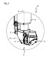
- the in the FIGS. 1 a and 1 b and in FIG. 2 cleaning device 1 shown has, on a frame, not shown, first a lifting drive 2, on the lifting drive 2, a rotary drive 3, on the rotary drive 3, a radial drive 4 and on the radial drive 4, a process head 5.
- the process head 5 of the cleaning device 1 consists essentially of a tube 6 and has a Lekssachsantrieb 7, by means of which the tube 6 is rotatable about its longitudinal axis 8.
- the process head 5 has a Querachsantrieb 9, by means of which an attached at the free end 10 of the tube 6 outlet member 11 is rotatable about a transversely to the longitudinal axis 8 transverse axis 12. By rotating about longitudinal axis 8 and transverse axis 12, the exit element 11 can be aligned in any direction in space.
- the cleaning device 1 has an infrared disk laser, not shown, with a pulsed light output of about 750 W and a wavelength of about 1030 nm.
- Laser beam 13 from the laser is deflected at the free end 10 of the tube 6 by means of a first mirror 14 in the direction of the transverse axis 12 and in the outlet element 11 by means of a second mirror 15 in the desired spatial direction in each case by a right angle.
- the cleaning device 1 further comprises a not-shown position optics for the laser beam 13, namely essentially a converging lens, by means of which the distance of a focal point of the laser beam 13 from the exit element 11 is adjustable.
- the cleaning device 1 Under the frame, the cleaning device 1, a likewise not shown, horizontally movable workpiece table, placed on the different body and can be aligned with their (shown in the following figures) symmetry axis 18 coaxial with the rotary drive 3.
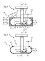
- FIG. 3 A first exemplary application of the cleaning device 1 is illustrated FIG. 3 On the workpiece table a tire mold 16 shown only stylized is deposited, by means of which a pneumatic tire for a motor vehicle can be "baked" from a green tire in a heating press.
- a second exemplary application is according to FIG. 4 on the workpiece table a likewise stylized tire 17, namely a pneumatic tire for a motor vehicle.
- the tire mold 16 and the tire 17 each have a substantially parallel to its axis of symmetry 18, cylindrical tread 19 and a substantially transverse to the tread 19 side wall 20.
- FIGS. 3 and 4 are the beam path of the laser beam 13 and the required for beam shaping optics simplified.
- the symmetry axis 18 of the tire mold 16 and of the tire 17 and the cleaning device 1 are aligned with each other and a straight circular cylinder 21 around the axis of symmetry 18 is determined, within which the process head 5 maintains a safety distance 22 to the surface on each circular path about the longitudinal axis 8.
- start positions of the process head 5 are established within the circular cylinder 21.
- the settings of the drives and the position optics are stored in a control module of the cleaning device 1.
- the process head 5 is successively delivered by means of the lifting drive 2 in parallel and by means of the radial drive 4 radially to the axis of symmetry 18 to the starting positions and by Leksachsantrieb 7 and Querachsantrieb 9, the exit element 11 rotates to the laser beam 13 on the associated impact point to align the surface, and the laser beam 13 focused by means of the stop optics on the impact point.
- the process head 5 is rotated by means of the rotary drive 3 about the axis of symmetry 18, so that the process head 5 starting from the start position, a circular path about the axis of symmetry 18 within the Circular cylinder 21 describes.
- the laser beam 13, starting from the impact point describes a circular path on the surface and cleans it.
- the process head 5 is initially guided with its longitudinal axis 8 parallel to the symmetry axis 18 from above to the bottom 23 of the tire mold 16 into the cavity for automated alignment.
- the distance of the process head 5 from the surface is measured in a direction which is the same for all measurements.
- the test level 24 in which the distance of the process head 5 from the surface has the smallest measured value is defined as the measurement plane 25.
- the measuring plane 25 intersects an upper edge 26 of the tire mold 16 on which the surface is smooth, ie in particular has no tire profile disturbing the measurement.
- the position of the symmetry axis 18 of the tire mold 16 in the measuring plane 25 is calculated and the tire mold 16 is displaced such that the longitudinal axis 8 of the process head 5 coincides with the axis of symmetry 18.
- the distance 27 of the surface from the symmetry axis 18 is calculated and reduced by the safety distance 22 of 5 mm:
- the radius 28 of the circular cylinder 21 is determined.
- Description calculates a distance of the process head 5 from an associated point on the surface, on which the laser beam 13 is focused.
Landscapes
- Engineering & Computer Science (AREA)
- Mechanical Engineering (AREA)
- Moulds For Moulding Plastics Or The Like (AREA)
Applications Claiming Priority (1)
| Application Number | Priority Date | Filing Date | Title |
|---|---|---|---|
| DE201310220066 DE102013220066B3 (de) | 2013-10-02 | 2013-10-02 | Verfahren zum Reinigen einer Oberfläche eines Hohlraums |
Publications (1)
| Publication Number | Publication Date |
|---|---|
| EP2857113A1 true EP2857113A1 (fr) | 2015-04-08 |
Family
ID=51582244
Family Applications (1)
| Application Number | Title | Priority Date | Filing Date |
|---|---|---|---|
| EP20140184720 Withdrawn EP2857113A1 (fr) | 2013-10-02 | 2014-09-15 | Procédé destiné au nettoyage d'une surface d'un espace creux |
Country Status (3)
| Country | Link |
|---|---|
| EP (1) | EP2857113A1 (fr) |
| DE (1) | DE102013220066B3 (fr) |
| WO (1) | WO2015049271A1 (fr) |
Cited By (2)
| Publication number | Priority date | Publication date | Assignee | Title |
|---|---|---|---|---|
| EP3312236B1 (fr) | 2016-10-24 | 2019-05-15 | Hankook Tire Co., Ltd. | Pneu à faible bruit de cavité et son procédé de fabrication |
| EP4359188A1 (fr) * | 2021-06-21 | 2024-05-01 | 4JET Technologies GmbH | Procédé et dispositif pour nettoyer au moins un segment de moule d'un moule de pneumatique par rayonnement laser |
Families Citing this family (15)
| Publication number | Priority date | Publication date | Assignee | Title |
|---|---|---|---|---|
| US10343194B2 (en) * | 2015-11-11 | 2019-07-09 | The Yokohama Rubber Co., Ltd. | Tire cleaning system |
| US10086577B2 (en) * | 2015-12-01 | 2018-10-02 | The Goodyear Tire & Rubber Company | Method of making a self-sealing tire, and a tire |
| US10099440B2 (en) | 2015-12-01 | 2018-10-16 | The Goodyear Tire & Rubber Company | Method of laser cleaning a tire inner surface, and a tire |
| CN108021098B (zh) * | 2017-12-05 | 2019-07-19 | 华中科技大学 | 一种自动生成轮胎模具安全圆柱体的刀具轨迹优化方法 |
| JP6590010B2 (ja) * | 2018-02-09 | 2019-10-16 | 横浜ゴム株式会社 | 加硫用モールドの洗浄装置および方法 |
| US11396150B2 (en) | 2018-02-14 | 2022-07-26 | Android Industries Llc | Tire preparation for adhesive using laser ablation system and method |
| CN109435115A (zh) * | 2018-11-15 | 2019-03-08 | 沈阳慧远自动化设备有限公司 | 一种用于轮胎模具激光清洗设备 |
| DE202019100947U1 (de) * | 2019-02-19 | 2019-03-04 | 4Jet Technologies Gmbh | Hochgeschwindigkeits-Reifenreinigungsvorrichtung |
| CN110883020A (zh) * | 2019-12-25 | 2020-03-17 | 钛昇科技股份有限公司 | 清模机 |
| CN111559103A (zh) * | 2020-05-21 | 2020-08-21 | 中国科学院半导体研究所 | 用于轮胎模具的激光清洗装置及方法 |
| CN112058809A (zh) * | 2020-09-04 | 2020-12-11 | 深圳市汇泽激光科技有限公司 | 一种激光清洗轮胎的装置及方法 |
| CN113910507A (zh) * | 2020-11-02 | 2022-01-11 | 沈阳工业大学 | 一种在线式轮胎模具激光清洗设备 |
| CN112810002A (zh) * | 2021-01-18 | 2021-05-18 | 温州职业技术学院 | 一种多功能轮胎模具块激光清洗装置 |
| DE202022102642U1 (de) | 2022-05-13 | 2022-06-13 | 4Jet Technologies Gmbh | Vorrichtung zum Öffnen von Ventilen, Laserreinigungsvorrichtung und Formenbearbeitungsanordnung |
| CN117443854A (zh) * | 2023-11-10 | 2024-01-26 | 山东玲珑轮胎股份有限公司 | 激光清洗方法及装置 |
Citations (8)
| Publication number | Priority date | Publication date | Assignee | Title |
|---|---|---|---|---|
| EP0366986A2 (fr) * | 1988-11-03 | 1990-05-09 | Umformtechnik ERFURT GmbH | Dispositif pour nettoyer un moule de machines à travailler les matières plastiques |
| EP0792731A2 (fr) * | 1996-03-01 | 1997-09-03 | PIRELLI COORDINAMENTO PNEUMATICI S.p.A. | Procédé et dispositif pour nettoyer des moules de vulcanisation d'articles en élastomère |
| JPH09277272A (ja) | 1996-04-09 | 1997-10-28 | Daido Steel Co Ltd | タイヤ成形用金型の外金型クリーニング装置 |
| JPH11199524A (ja) | 1998-01-08 | 1999-07-27 | Mitsubishi Chemical Corp | 壁面降下型溶融晶析方法 |
| DE19936698C1 (de) * | 1999-08-04 | 2000-12-21 | Continental Ag | Vorrichtung zur Reinigung von Vulkanisationsformen |
| DE19933195A1 (de) * | 1999-07-15 | 2001-01-18 | Forma Formen Und Maschb Gmbh | Vorrichtung und Verfahren zum Reinigen und/oder Beschichten der Formoberfläche einer Form |
| EP1604809A1 (fr) | 2004-06-10 | 2005-12-14 | The Goodyear Tire & Rubber Company | Méthode et dispositif pour la préparation d'une surface d'un pneumatique pour l'installation d'un dispositif éléctronique |
| EP2674287A1 (fr) | 2012-06-11 | 2013-12-18 | Continental Reifen Deutschland GmbH | Procédé d'application d'une couche de protection anti-crevaison auto-étanche sur l'intérieur d'un pneumatique de véhicule |
Family Cites Families (2)
| Publication number | Priority date | Publication date | Assignee | Title |
|---|---|---|---|---|
| JPH01199524A (ja) | 1988-02-03 | 1989-08-10 | Toyoaki Mizuta | 植物栽培用レキの製造方法 |
| JPH1199524A (ja) * | 1997-09-29 | 1999-04-13 | Fuji Industries:Kk | 金型クリーニング装置 |
-
2013
- 2013-10-02 DE DE201310220066 patent/DE102013220066B3/de not_active Expired - Fee Related
-
2014
- 2014-09-15 EP EP20140184720 patent/EP2857113A1/fr not_active Withdrawn
- 2014-10-01 WO PCT/EP2014/071013 patent/WO2015049271A1/fr not_active Ceased
Patent Citations (8)
| Publication number | Priority date | Publication date | Assignee | Title |
|---|---|---|---|---|
| EP0366986A2 (fr) * | 1988-11-03 | 1990-05-09 | Umformtechnik ERFURT GmbH | Dispositif pour nettoyer un moule de machines à travailler les matières plastiques |
| EP0792731A2 (fr) * | 1996-03-01 | 1997-09-03 | PIRELLI COORDINAMENTO PNEUMATICI S.p.A. | Procédé et dispositif pour nettoyer des moules de vulcanisation d'articles en élastomère |
| JPH09277272A (ja) | 1996-04-09 | 1997-10-28 | Daido Steel Co Ltd | タイヤ成形用金型の外金型クリーニング装置 |
| JPH11199524A (ja) | 1998-01-08 | 1999-07-27 | Mitsubishi Chemical Corp | 壁面降下型溶融晶析方法 |
| DE19933195A1 (de) * | 1999-07-15 | 2001-01-18 | Forma Formen Und Maschb Gmbh | Vorrichtung und Verfahren zum Reinigen und/oder Beschichten der Formoberfläche einer Form |
| DE19936698C1 (de) * | 1999-08-04 | 2000-12-21 | Continental Ag | Vorrichtung zur Reinigung von Vulkanisationsformen |
| EP1604809A1 (fr) | 2004-06-10 | 2005-12-14 | The Goodyear Tire & Rubber Company | Méthode et dispositif pour la préparation d'une surface d'un pneumatique pour l'installation d'un dispositif éléctronique |
| EP2674287A1 (fr) | 2012-06-11 | 2013-12-18 | Continental Reifen Deutschland GmbH | Procédé d'application d'une couche de protection anti-crevaison auto-étanche sur l'intérieur d'un pneumatique de véhicule |
Cited By (2)
| Publication number | Priority date | Publication date | Assignee | Title |
|---|---|---|---|---|
| EP3312236B1 (fr) | 2016-10-24 | 2019-05-15 | Hankook Tire Co., Ltd. | Pneu à faible bruit de cavité et son procédé de fabrication |
| EP4359188A1 (fr) * | 2021-06-21 | 2024-05-01 | 4JET Technologies GmbH | Procédé et dispositif pour nettoyer au moins un segment de moule d'un moule de pneumatique par rayonnement laser |
Also Published As
| Publication number | Publication date |
|---|---|
| WO2015049271A1 (fr) | 2015-04-09 |
| DE102013220066B3 (de) | 2014-12-18 |
Similar Documents
| Publication | Publication Date | Title |
|---|---|---|
| DE102013220066B3 (de) | Verfahren zum Reinigen einer Oberfläche eines Hohlraums | |
| EP2695728B1 (fr) | Dispositif destinés au nettoyage de moules de vulcanisation | |
| EP2670557B1 (fr) | Procédé pour séparer une section de bord d'une pièce par une coupe de séparation au laser ainsi que dispositif de coupe au laser associé | |
| DE102014011301A1 (de) | Verfahren zum Erzeugen einer Relativbewegung zwischen einer Strahleinheit und einer gekrümmten Oberfläche | |
| DE102008011998A1 (de) | Anordnung zum Beschichten von Werkstücken | |
| WO2013079395A1 (fr) | Procédé de positionnement d'un système de mesure et système de mesure pour mettre en oeuvre le procédé | |
| WO2016015695A1 (fr) | Détermination au moyen d'une caméra de la rugosité de composants fabriqués de manière générative | |
| EP2987630A1 (fr) | Procédé de fabrication d'un moule pour la vulcanisation pour pneus et moule pour la vulcanisation pour pneus | |
| EP2615413A1 (fr) | Procédé et dispositif de suppression d'erreurs dans une pièce de carosserie de véhicule | |
| WO2016116367A1 (fr) | Procédé et installation de revêtement pour appliquer un revêtement sur des parois de cavités | |
| EP3776110B1 (fr) | Procédé de création de données d'usinage 3d d'une jante de véhicule automobile | |
| EP3260272A1 (fr) | Dispositif de fabrication d'au moins un composant tridimensionnel pour l'industrie de la construction | |
| DE102007048588A1 (de) | Verfahren zum Nachbearbeiten eines extern vorgefertigten Formteils | |
| EP3190093B1 (fr) | Dispositif de fabrication de produits en verre creux | |
| EP2834039B1 (fr) | Procédé de peinture de pièces automobiles en matière plastique, en particulier de pare-chocs de véhicules automobiles | |
| WO2019211380A1 (fr) | Dispositif pour positionner un système de lavage pour moteurs à réaction dans l'entrée du moteur | |
| DE102017108031B4 (de) | Verfahren und Fertigungsvorrichtung zum lagenweisen Aufbau eines durch Geometriebeschreibungsdaten definierten Formkörpers | |
| DE102010040931B4 (de) | Vorrichtung zur Nachbearbeitung von zwei Bauteilen sowie Verfahren | |
| DE102012111439A1 (de) | Extrusionsvorrichtung | |
| DE102004006164B4 (de) | Verfahren zum Fräsen einer Nut auf einem Zylindermantel | |
| DE10306741B3 (de) | Verfahren und Vorrichtung zum maschinellen Abrauhen von abgenutzten Reifen | |
| DE102018201656A1 (de) | Vorrichtung zum automatischen Ausrichten eines Frontendmoduls an einem Rohbau eines Kraftfahrzeuges und Verfahren zum automatischen Ausrichten eines Frontendmoduls an einem Rohbau eines Kraftfahrzeuges | |
| DE4220708C2 (de) | Verfahren zum Herstellen von einzelnen, endlichen Laufflächen in Form von Halbfabrikaten für Reifen, insbesondere Kraftfahrzeug-Reifen | |
| WO2017050813A1 (fr) | Procédé pour mesurer un niveau de pression acoustique d'une bobine d'induction haute tension ou d'un transformateur haute tension | |
| DE19848290C2 (de) | Vorrichtung und Verfahren zum Herstellen schalenförmiger Bauteile aus Metall sowie schalenförmiges Bauteil aus Metall |
Legal Events
| Date | Code | Title | Description |
|---|---|---|---|
| PUAI | Public reference made under article 153(3) epc to a published international application that has entered the european phase |
Free format text: ORIGINAL CODE: 0009012 |
|
| 17P | Request for examination filed |
Effective date: 20140915 |
|
| AK | Designated contracting states |
Kind code of ref document: A1 Designated state(s): AL AT BE BG CH CY CZ DE DK EE ES FI FR GB GR HR HU IE IS IT LI LT LU LV MC MK MT NL NO PL PT RO RS SE SI SK SM TR |
|
| AX | Request for extension of the european patent |
Extension state: BA ME |
|
| STAA | Information on the status of an ep patent application or granted ep patent |
Free format text: STATUS: THE APPLICATION IS DEEMED TO BE WITHDRAWN |
|
| 18D | Application deemed to be withdrawn |
Effective date: 20151009 |