EP2857217B1 - Procédé de réalisation d'un dispositif de sécurité comprenant deux motifs optiquement variables associés de couleurs différentes - Google Patents
Procédé de réalisation d'un dispositif de sécurité comprenant deux motifs optiquement variables associés de couleurs différentes Download PDFInfo
- Publication number
- EP2857217B1 EP2857217B1 EP14187797.7A EP14187797A EP2857217B1 EP 2857217 B1 EP2857217 B1 EP 2857217B1 EP 14187797 A EP14187797 A EP 14187797A EP 2857217 B1 EP2857217 B1 EP 2857217B1
- Authority
- EP
- European Patent Office
- Prior art keywords
- pattern
- ink
- colors
- optically variable
- modification
- Prior art date
- Legal status (The legal status is an assumption and is not a legal conclusion. Google has not performed a legal analysis and makes no representation as to the accuracy of the status listed.)
- Active
Links
Images

Classifications
-
- B—PERFORMING OPERATIONS; TRANSPORTING
- B42—BOOKBINDING; ALBUMS; FILES; SPECIAL PRINTED MATTER
- B42D—BOOKS; BOOK COVERS; LOOSE LEAVES; PRINTED MATTER CHARACTERISED BY IDENTIFICATION OR SECURITY FEATURES; PRINTED MATTER OF SPECIAL FORMAT OR STYLE NOT OTHERWISE PROVIDED FOR; DEVICES FOR USE THEREWITH AND NOT OTHERWISE PROVIDED FOR; MOVABLE-STRIP WRITING OR READING APPARATUS
- B42D25/00—Information-bearing cards or sheet-like structures characterised by identification or security features; Manufacture thereof
- B42D25/40—Manufacture
- B42D25/405—Marking
- B42D25/41—Marking using electromagnetic radiation
-
- B—PERFORMING OPERATIONS; TRANSPORTING
- B41—PRINTING; LINING MACHINES; TYPEWRITERS; STAMPS
- B41M—PRINTING, DUPLICATING, MARKING, OR COPYING PROCESSES; COLOUR PRINTING
- B41M3/00—Printing processes to produce particular kinds of printed work, e.g. patterns
- B41M3/14—Security printing
- B41M3/148—Transitory images, i.e. images only visible from certain viewing angles
-
- B—PERFORMING OPERATIONS; TRANSPORTING
- B42—BOOKBINDING; ALBUMS; FILES; SPECIAL PRINTED MATTER
- B42D—BOOKS; BOOK COVERS; LOOSE LEAVES; PRINTED MATTER CHARACTERISED BY IDENTIFICATION OR SECURITY FEATURES; PRINTED MATTER OF SPECIAL FORMAT OR STYLE NOT OTHERWISE PROVIDED FOR; DEVICES FOR USE THEREWITH AND NOT OTHERWISE PROVIDED FOR; MOVABLE-STRIP WRITING OR READING APPARATUS
- B42D25/00—Information-bearing cards or sheet-like structures characterised by identification or security features; Manufacture thereof
-
- B—PERFORMING OPERATIONS; TRANSPORTING
- B42—BOOKBINDING; ALBUMS; FILES; SPECIAL PRINTED MATTER
- B42D—BOOKS; BOOK COVERS; LOOSE LEAVES; PRINTED MATTER CHARACTERISED BY IDENTIFICATION OR SECURITY FEATURES; PRINTED MATTER OF SPECIAL FORMAT OR STYLE NOT OTHERWISE PROVIDED FOR; DEVICES FOR USE THEREWITH AND NOT OTHERWISE PROVIDED FOR; MOVABLE-STRIP WRITING OR READING APPARATUS
- B42D25/00—Information-bearing cards or sheet-like structures characterised by identification or security features; Manufacture thereof
- B42D25/20—Information-bearing cards or sheet-like structures characterised by identification or security features; Manufacture thereof characterised by a particular use or purpose
- B42D25/29—Securities; Bank notes
-
- B—PERFORMING OPERATIONS; TRANSPORTING
- B42—BOOKBINDING; ALBUMS; FILES; SPECIAL PRINTED MATTER
- B42D—BOOKS; BOOK COVERS; LOOSE LEAVES; PRINTED MATTER CHARACTERISED BY IDENTIFICATION OR SECURITY FEATURES; PRINTED MATTER OF SPECIAL FORMAT OR STYLE NOT OTHERWISE PROVIDED FOR; DEVICES FOR USE THEREWITH AND NOT OTHERWISE PROVIDED FOR; MOVABLE-STRIP WRITING OR READING APPARATUS
- B42D25/00—Information-bearing cards or sheet-like structures characterised by identification or security features; Manufacture thereof
- B42D25/30—Identification or security features, e.g. for preventing forgery
- B42D25/36—Identification or security features, e.g. for preventing forgery comprising special materials
- B42D25/378—Special inks
-
- B42D2033/10—
-
- B42D2033/16—
-
- B42D2033/20—
-
- B42D2035/50—
Definitions
- the present invention relates to a method of manufacturing a safety device.
- a security device is used to authenticate the origin or issuer of a secure document.
- a secure document is, for example, an identity document such as an identity card or a passport.
- On this document to secure is affixed a security device that attests the authority of the issuer.
- An optically variable ink makes it possible to print a pattern that has the interesting property of changing color, among at least two colors, functions of the angle at which the pattern is observed.
- the problem at the origin of the present invention is to position two patterns relative to each other, a first pattern having at least two colors, functions of the angle at which the pattern is observed and a second pattern having at least two colors, functions of the angle at which the pattern is observed, the colors of the second pattern being different from the colors of the first pattern.
- the invention relates to a method for producing a security device comprising the steps of: printing on a support of a first pattern with a first optically variable ink making it possible to see a red color at an incidence of less than 45.degree. to the direction of specular reflection and to see a green color under an incidence greater than 45 ° with respect to this direction of specular reflection, formation on this support of a second pattern, associated with the first pattern, so as to present two other function of the angle of observation, the formation of the second pattern comprises printing the second pattern in the same pass as for printing the first pattern, with the first optically variable ink, and a step of modifying the first pattern.
- the modification is carried out using a mask covering at least the entire second pattern.
- said mask covers at least the entire second pattern increased by a margin all around its periphery.
- the power of the laser is equal to 2.4 W.
- the second pattern is similar to the first pattern, in that it is deduced from the first pattern by a similarity.
- a support 1 is seen in cross section.
- a pattern 6 by means of an optically variable ink.
- the properties of an optically variable ink make it possible to see the printed pattern 6 appear in a first color, when the observation direction lies in the light angular sector 4, delimited by the two dashed segments, substantially between +/- - 45 ° relative to the direction 3, and a second color when the direction of observation is included in the complementary hatched angular sector.
- the figure 2 illustrates an example of what we want to achieve. It is a safety device 5 comprising a first pattern 6 and a second pattern 7.
- the first pattern 6 is printed with a first optically variable ink. Also, the first pattern 6 has two first colors functions of the angle of observation. These first colors are represented by a "grid" texture.
- the second pattern 7 is printed with a second optically variable ink. Also, the second pattern 6 has two second colors functions of the viewing angle. These second colors are represented by a "brick" texture.
- the safety device has two characteristics.
- the first pattern 6 and the second pattern 7 must be geometrically associated. In other words, there must be a geometric association relation between the two motifs 6,7.
- the second colors of the second pattern 7 must be different from the first colors of the first pattern 6.
- the two motifs should be precisely positioned in relation to each other, as is usually the case, the north-east corner of the Sicilian "triangle" opposite the end of the tip of the Italian boot.
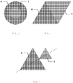
- the Figures 2-5 illustrate different relationships that can geometrically associate the two patterns 6,7.
- a geometric association is characterized by a relative precise positioning of the two patterns 6.7 with respect to each other.
- Such an association is detectable and verifiable with the naked eye.
- Such an association is still characterized by an implicit or explicit harmony that the human eye perceives and recognizes even if it did not have prior knowledge of it.
- Such an association is further characterized by the fact that the disappearance of the geometric association is immediately detectable to the naked eye, even in the absence of previously known model.
- the figure 2 illustrates a first embodiment where the geometric association between the first pattern 6 and the second pattern is an alignment relation.
- the first pattern 6 and the second pattern 7 are aligned vertically, exactly at the same height. If this alignment was not perfect, due to a defect in positioning of either of the patterns 6.7, the eye would detect it immediately, even without knowing the safety device 5 and the patterns 6.7 as represented in the figure 2 .
- the figure 2 illustrates again a relation of identity, the two motifs 6,7 being the same, with the same size, with a close symmetry.
- the figure 3 illustrates another embodiment where the geometric association between the first pattern 6 and the second pattern is expressed by a concentricity relation.
- the large disk of the first pattern 6 and the small disk of the second pattern 7 are exactly concentric. If this concentricity was not perfect, because of a lack of positioning of either of the two patterns 6,7, the eye would detect it immediately, even without having a prior knowledge of the representation of the figure 3 .
- the figure 4 illustrates another embodiment where the geometric association between the first pattern 6 and the second pattern is a relationship of contact, contiguity or tangency.
- one of the sides of the triangle of the first pattern 6 and one of the sides of the triangle of the second pattern 7 are exactly in contact. If this contact was not perfect, because of a defect in positioning or orientation of either of the two patterns 6.7, the eye would detect it immediately, even without having a prior knowledge of the desired representation.
- the figure 4 further illustrates an alignment relationship between the two adjacent sides of the patterns 6, 7 which not only are in contact (parallel) but whose ends coincide.
- the figure 5 illustrates another embodiment where the geometric association between the first pattern 6 and the second pattern is expressed by a relationship of proportion.
- the large triangle of the first pattern 6 has an exactly double size of the small triangle of the second pattern 7.
- the two patterns are in a homothetic ratio of 2. Such a ratio is perceptible by the eye, which would detect a lack of harmony, equilibrium, for a ratio of 1.8 or 2.2.
- the figure 5 further illustrates a contact relationship in that one of the vertices of the triangle of the second pattern 7 is in contact with one side of the triangle of the first pattern 6.
- the figure 5 illustrates yet another relationship of proportion in that said contact is disposed in the middle of said side.
- the figure 5 illustrates again an alignment relation in that the triangles of the two patterns, despite their difference in size, are aligned in that they share the same median.
- the two motifs are edge to edge, the two motifs are in the extension, the two motifs are at the same height, at the same level, and so on.
- the second ink used to print the second pattern 7 is identical to the first ink.
- At least the second ink is modified so that the second colors are modified and the second pattern 7 has different colors from the colors of the first pattern 6.
- the first ink of the first pattern is typically unmodified to present a pair of first colors, different from the second colors obtained by modification.
- the first ink, or additionally a third ink may be modified according to a different modification, typically in its intensity, of the modification applied to the second ink, in order to present a pair of third colors, different from the first colors and different from the second ones. colors.
- the modification applied to an ink should be irreversible, so that the new colors, obtained by modification, are persistent in time. Also, if the modification process is not based on an irreversible physical principle, it should be supplemented by a step to fix the result of the change in time.
- the modification is performed by a global operation that modifies the entire second pattern 7 in a single application.
- a global operation that modifies the entire second pattern 7 in a single application.
- an application means or mask covering at least the whole of the pattern 7 to be modified.
- the application means or mask covers a surface exceeding the pattern 7 to be modified in all directions.
- the mask can thus have the shape of the pattern 7 increased all around its margin.
- the mask may still have a simple shape such as a square or round circumscribed said pattern 7 increased all around a margin. This is advantageous from the operational point of view because said margin allows a coarse positioning of the safety device relative to the modification tooling. This makes it possible to carry out the modification operation more quickly, with less tools and thus at a lower cost.
- pre-personalization makes it possible to place a national badge, such as a flag or a card, in a security device.
- the modification is carried out by means of a laser.
- the operation carried out using a laser is distinctly different from that for engraving in an inner layer of plastic and commonly used in the field of security devices, for example to customize such a safety device.
- the modification laser is applied at a much lower power.
- the laser power used for a modification operation is between 0.5 and 4W.
- a power equal to 2.4W appears satisfactory. This power is to be compared to a power of 10 W required for customization engraving. It follows that the lower power used for the modification remains completely neutral and has no effect for the support of the safety device.
- a variation of the laser power applied makes it possible to vary the second colors obtained.
- the modification laser may, as previously described, be applied in a solid, overall manner by means of a mask covering the modified pattern in its entirety.
- the mask can cover a surface exceeding the pattern 7 to be modified and comprising a margin around said pattern 7.
- the second ink is initially identical to the first ink, during the printing operation, which advantageously makes it possible to satisfy the geometric association characteristic, realizing the different patterns 6.7 in one and the same pass.
- Said second ink is then modified, by modifying its physical properties, by means of a laser, in order to reveal second modified colors different from the first initial colors.
- the color change angle substantially +/- 45 ° around the specular reflection direction 3 remains unchanged by the modification operation.
- the first and second patterns 6.7 are printed with the same ink and during the same pass. A print in two passes, or with different inks would have no chance to reproduce such a feature.
- a similarity is a geometric transformation obtained by composition of a homothety and an isometry.
- An isometry is a geometric transformation that retains the dimensions and angles and thus the shape of a pattern.
- the isometries include, translations, rotations and orthogonal reflections or symmetries according to an axis, as well as all their compounds.
- the invention relates to the method of producing such a security device 5.
- This method comprises the following steps: printing a first pattern 6 with a first optically variable ink, so as to have two first colors functions of the angle observation, printing a second pattern 7, geometrically associated with the first pattern 6, with a second optically variable ink, so as to have two second colors functions of the viewing angle, the second ink being initially identical to the first ink, and then modifying the second ink, so as to have two different second colors of the first two colors.
- a characteristic of the invention which is particularly advantageous in that it makes it possible to preserve the geometric association of the two patterns 6, 7, the printing of the first pattern 6 and the printing of the second pattern 7 are carried out in the same pass. This is made possible by the fact that the second ink is identical to the first ink.
Landscapes
- Business, Economics & Management (AREA)
- Accounting & Taxation (AREA)
- Finance (AREA)
- Physics & Mathematics (AREA)
- Health & Medical Sciences (AREA)
- Electromagnetism (AREA)
- General Health & Medical Sciences (AREA)
- Toxicology (AREA)
- Engineering & Computer Science (AREA)
- Manufacturing & Machinery (AREA)
- Printing Methods (AREA)
Description
- La présente invention concerne un procédé de fabrication d'un dispositif de sécurité. Un dispositif de sécurité est employé afin d'authentifier l'origine ou l'émetteur d'un document sécurisé. Un tel document sécurisé est, par exemple, un document identitaire tel une carte d'identité ou un passeport. Sur ce document à sécuriser est apposé un dispositif de sécurité qui atteste de l'autorité de l'émetteur.
- Il est connu d'employer des encres spéciales, difficiles à approvisionner ou à reproduire par un faussaire, et offrant des propriétés visibles et ainsi avantageusement contrôlables visuellement, sans outillage spécifique. Une encre optiquement variable permet d'imprimer un motif qui présente la propriété intéressante de changer de couleur, parmi au moins deux couleurs, fonctions de l'angle selon lequel le motif est observé.
- Le problème à l'origine de la présente invention est de positionner deux motifs l'un par rapport à l'autre, un premier motif présentant au moins deux couleurs, fonctions de l'angle selon lequel le motif est observé et un deuxième motif présentant au moins deux couleurs, fonctions de l'angle selon lequel le motif est observé, les couleurs du deuxième motif étant différentes des couleurs du premier motif.
- Une solution évidente consisterait à imprimer le premier motif avec une première encre optiquement variable et le deuxième motif avec une deuxième encre optiquement variable, de composition différente, afin de produire des couleurs différentes. Le livre de référence de Rudolf L. van Renesse: "Optical Document Security (Third Edition)", 2005, Artech House, Boston / London, en page 349, décrit une telle solution, qui est le préambule de la revendication 1. Ceci permettrait d'obtenir deux motifs dont les couleurs sont différentes. Cependant, le fait de changer d'encre entre le premier motif et le deuxième motif nécessiterait deux passes séparées. Il n'est pas possible actuellement de positionner deux passes d'impression l'une relativement à l'autre, de manière suffisamment précise pour conserver une association entre les deux motifs.
- Aussi un autre moyen de réaliser deux motifs associés, imprimés avec une encre optiquement variable mais présentant des couleurs différentes a dû être trouvé.
- L'invention concerne un procédé de réalisation d'un dispositif de sécurité comprenant les étapes de : impression sur un support d'un premier motif avec une première encre optiquement variable permettant de voir une couleur rouge sous une incidence inférieure à 45°, par rapport à la direction de réflexion spéculaire et de voir une couleur verte sous une incidence plus grande que 45° par rapport à cette direction de réflexion spéculaire, formation sur ce support d'un deuxième motif, associé au premier motif, de manière à présenter deux autres couleurs fonctions de l'angle d'observation, la formation du deuxième motif comporte l'impression du deuxième motif dans une même passe que pour l'impression du premier motif, avec la première encre optiquement variable, et une étape de modification de la première encre du deuxième motif en la deuxième encre, au moyen d'un laser appliqué à ce deuxième motif à une puissance comprise entre 0,5 et 4 W suffisamment faible pour ne pas effectuer de gravure dudit support, de manière à ce que la première encre avec laquelle le deuxième motif a été imprimé présente lesdites autres couleurs.
- Selon une autre caractéristique, la modification est réalisée à l'aide d'un masque couvrant au moins tout le deuxième motif.
- Selon une autre caractéristique, ledit masque couvre au moins tout le deuxième motif augmenté d'une marge sur tout son pourtour.
- Selon une autre caractéristique, la puissance du laser est égale à 2,4 W.
- Selon une autre caractéristique, le deuxième motif est semblable au premier motif, en ce qu'il se déduit du premier motif par une similitude.
- D'autres caractéristiques, détails et avantages de l'invention ressortiront plus clairement de la description détaillée donnée ci-après à titre indicatif en relation avec des dessins sur lesquels :
- la
figure 1 illustre les propriétés d'une encre optiquement variable, le dispositif étant vu de profil, - les
figures 2-5 illustrent différentes associations géométriques entre motifs. - Selon la
figure 1 , un support 1 est vu en section transversale. Sur ce support 1 est imprimé un motif 6 au moyen d'une encre optiquement variable. Est indiquée une direction 2 d'éclairage du support 1 ainsi que la direction 3 de réflexion spéculaire correspondante. Les propriétés d'une encre optiquement variable permettent de voir le motif 6 imprimé apparaitre d'une première couleur, lorsque la direction d'observation est comprise dans le secteur angulaire clair 4, délimité par les deux segments en pointillés, sensiblement compris entre +/- 45° relativement à la direction 3, et d'une deuxième couleur lorsque la direction d'observation est comprise dans le secteur angulaire hachuré complémentaire. - En fonction de l'encre optiquement variable choisie, il est possible d'obtenir différentes couleurs. Ainsi, par exemple, il existe une encre permettant de voir une couleur rouge sous une incidence faible (<45°), par rapport à la direction 3 de réflexion spéculaire et de voir une couleur verte sous une incidence plus grande (>45°) par rapport à la direction 3 de réflexion spéculaire.
- La
figure 2 illustre un exemple de ce que l'on souhaite réaliser. Il s'agit d'un dispositif de sécurité 5 comprenant un premier motif 6 et un deuxième motif 7. Le premier motif 6 est imprimé avec une première encre optiquement variable. Aussi, le premier motif 6 présente deux premières couleurs fonctions de l'angle d'observation. Ces premières couleurs sont figurées par une texture « quadrillage ». Le deuxième motif 7 est imprimé avec une deuxième encre optiquement variable. Aussi, le deuxième motif 6 présente deux deuxièmes couleurs fonctions de l'angle d'observation. Ces deuxièmes couleurs sont figurées par une texture « brique ». - Il est encore souhaité que le dispositif de sécurité présente deux caractéristiques. D'une part le premier motif 6 et le deuxième motif 7 doivent être géométriquement associés. Autrement dit il doit exister une relation d'association géométrique entre les deux motifs 6,7. D'autre part les deuxièmes couleurs du deuxième motif 7 doivent être différentes des premières couleurs du premier motif 6.
- Ainsi dans l'exemple de la
figure 2 les deux oiseaux sont associés en ce que les becs se font face et se correspondent. - Un autre exemple, non représenté, pourrait être une carte de l'Italie comprenant la Sicile. Le premier motif, constitué par la presqu'ile italienne, apparait avec une première paire de couleurs, tandis que le deuxième motif, constitué par l'île sicilienne, apparait avec une deuxième paire de couleurs différente de la première. Afin de ne pas choquer un observateur, il convient que les deux motifs soit précisément positionnés l'un par rapport à l'autre, tels qu'habituellement, soit le coin nord-est du « triangle » sicilien en vis-à-vis de l'extrémité de la pointe de la botte italienne.
- Les
figures 2-5 illustrent différentes relations qui peuvent associer géométriquement les deux motifs 6,7. De manière générale une association géométrique se caractérise par un positionnement précis relatif des deux motifs 6,7 l'un par rapport à l'autre. Une telle association est détectable et vérifiable à l'oeil nu. Une telle association se caractérise encore par une harmonie implicite ou explicite que l'oeil humain perçoit et reconnaît même s'il n'en avait pas de connaissance préalable. Une telle association se caractérise encore par le fait que la disparition de l'association géométrique est immédiatement détectable à l'oeil nu, même en l'absence de modèle préalablement connu. - La
figure 2 illustre un premier mode de réalisation où l'association géométrique entre le premier motif 6 et le deuxième motif est une relation d'alignement. Ainsi le premier motif 6 et le deuxième motif 7 sont alignés verticalement, exactement à la même hauteur. Si cet alignement n'était pas parfait, du fait d'un défaut de positionnement de l'un ou l'autre des deux motifs 6,7, l'oeil le détecterait immédiatement, même sans connaitre le dispositif de sécurité 5 et les motifs 6,7 tels que représentés à lafigure 2 . - La
figure 2 illustre encore une relation d'identité, les deux motifs 6,7 étant les mêmes, à la même taille, à une symétrie près. - La
figure 3 illustre un autre mode de réalisation où l'association géométrique entre le premier motif 6 et le deuxième motif s'exprime par une relation de concentricité. Le grand disque du premier motif 6 et le petit disque du deuxième motif 7 sont exactement concentriques. Si cette concentricité n'était pas parfaite, du fait d'un défaut de positionnement de l'un ou l'autre des deux motifs 6,7, l'oeil le détecterait immédiatement, même sans avoir une connaissance préalable de la représentation de lafigure 3 . - La
figure 4 illustre un autre mode de réalisation où l'association géométrique entre le premier motif 6 et le deuxième motif est une relation de contact, de contiguïté ou encore de tangence. Ainsi un des côtés du triangle du premier motif 6 et un des côtés du triangle du deuxième motif 7 sont exactement en contact. Si ce contact n'était pas parfait, du fait d'un défaut de positionnement ou d'orientation de l'un ou l'autre des deux motifs 6,7, l'oeil le détecterait immédiatement, même sans avoir une connaissance préalable de la représentation souhaitée. - La
figure 4 illustre encore une relation d'alignement entre les deux côtés adjacents des motifs 6,7, qui non seulement sont en contact (parallèles), mais dont les extrémités coïncident. - La
figure 5 illustre un autre mode de réalisation où l'association géométrique entre le premier motif 6 et le deuxième motif s'exprime par une relation de proportion. Ainsi le grand triangle du premier motif 6 présente une taille exactement double du petit triangle du deuxième motif 7. Les deux motifs sont dans un rapport homothétique de 2. Un tel rapport est perceptible par l'oeil, qui détecterait un manque d'harmonie, d'équilibre, pour un rapport de 1,8 ou de 2,2. - La
figure 5 illustre encore une relation de contact en ce que l'un des sommets du triangle du deuxième motif 7 est en contact avec un côté du triangle du premier motif 6. - La
figure 5 illustre encore une autre relation de proportion en ce que ledit contact est disposé au milieu du dit côté. - La
figure 5 illustre encore une relation d'alignement en ce que les triangles des deux motifs, malgré leur différence de taille, sont alignés en ce qu'ils partagent une même médiane. - Les termes indicatifs d'une telle association géométrique sont encore : les deux motifs sont bord à bord, les deux motifs sont dans le prolongement, les deux motifs sont à la même hauteur, au même niveau, etc.
- L'homme du métier pourrait multiplier à loisir les configurations dans lesquelles un premier motif 6 est géométriquement associé à un deuxième motif 7.
- De manière pratique, il peut être retenu qu'une association géométrique se caractérise en ce qu'un léger déplacement ou une légère désorientation d'un motif 6,7 relativement à l'autre est détectable par l'oeil, en ce qu'une harmonie naturelle est rompue.
- Pour que la caractéristique de couleur soit vérifiée, à savoir que la paire de deuxièmes couleurs du deuxième motif 7 soit différente de la paire des premières couleurs du premier motif 6, une solution évidente est d'employer deux encres optiquement variables différentes. Cependant, lors de la mise en oeuvre d'une telle solution, il est impossible de réaliser le changement d'encre en cours d'opération d'impression. Aussi il est nécessaire de réaliser au moins deux passes d'impression, une passe par encre. En l'état actuel des techniques, il n'est pas possible de caler deux telles passes d'impression avec une précision suffisante pour conserver une association géométrique telle que définie précédemment. Aussi une telle solution n'est pas satisfaisante en ce qu'elle détruit l'association géométrique et ne répond pas à la caractéristique d'association géométrique.
- Selon une caractéristique importante de l'invention, ce problème est résolu, de manière particulièrement ingénieuse, de la manière suivante. La deuxième encre, utilisée pour imprimer le deuxième motif 7 est identique à la première encre.
- Ceci permet avantageusement de réaliser l'impression du premier motif 6 et l'impression du deuxième motif 7 en une seule passe d'impression et ainsi de satisfaire à la caractéristique de positionnement relatif précis des deux motifs qui permet de réaliser l'association géométrique.
- Ensuite, il est procédé à une modification d'au moins la deuxième encre afin que les deuxièmes couleurs soient modifiées et que le deuxième motif 7 présente des couleurs différentes des couleurs du premier motif 6.
- La première encre du premier motif est typiquement non modifiée afin de présenter une paire de premières couleurs, différentes des deuxièmes couleurs obtenues par modification.
- Alternativement la première encre, ou complémentairement une troisième encre, peut être modifiée selon une modification différente, typiquement dans son intensité, de la modification appliquée à la deuxième encre, afin de présenter une paire de troisièmes couleurs, différentes des premières couleurs et différentes des deuxièmes couleurs.
- Afin que le dispositif de sécurité soit effectif, il convient que la modification appliquée à une encre soit irréversible, afin que les nouvelles couleurs, obtenues par modification, soit persistantes dans le temps. Aussi si le procédé de modification n'est pas basé sur un principe physique irréversible, il convient de le compléter par une étape permettant de fixer le résultat de la modification dans le temps.
- Selon un mode de réalisation particulièrement avantageux, la modification est réalisée par une opération globale réalisant la modification de la totalité du deuxième motif 7 en une seule application. Un tel mode de réalisation emploie pour cela, fonction de la technologie de modification, un moyen d'application ou masque couvrant au moins l'ensemble du motif 7 à modifier.
- Ceci est important du point de vue opérationnel, car une telle opération peut ainsi être réalisée globalement et ainsi très rapidement.
- Selon un mode de réalisation particulièrement avantageux, le moyen d'application ou masque couvre une surface outrepassant le motif 7 à modifier dans toutes les directions. Le masque peut ainsi présenter la forme du motif 7 augmentée sur tout son pourtour d'une marge. Le masque peut encore présenter une forme simple telle un carré ou un rond circonscrit audit motif 7 augmenté sur tout son pourtour d'une marge. Ceci est avantageux du point de vue opérationnel car ladite marge permet un positionnement grossier du dispositif de sécurité relativement à l'outillage de modification. Ceci permet de réaliser l'opération de modification plus rapidement, avec moins d'outillage et ainsi à moindre coût.
- Il convient pour que cela soit possible que l'opération de modification soit neutre pour le support du dispositif de sécurité. Ainsi l'encre dans le motif 7 est modifiée, le support, notamment dans ladite marge doit rester non affecté par l'opération de modification.
- Il est important de remarquer que l'on n'adresse pas ici une opération de type personnalisation ou chaque dispositif de sécurité unitaire est individué et où l'opération doit nécessairement être réalisée dispositif de sécurité 5 par dispositif de sécurité. A titre illustratif une personnalisation permet de placer la photo du porteur dans un dispositif de sécurité.
- Au contraire, une telle approche pouvant être réalisée au moyen d'un masque modifiant en une seule présentation la totalité du motif à modifier, permet avantageusement d'adresser une opération de pré-personnalisation où les dispositifs de sécurité sont traités à l'identique sur des séries de 100, 1000 pièces ou davantage. A titre illustratif une pré-personnalisation permet de placer un insigne national, tel un drapeau ou une carte, dans un dispositif de sécurité.
- La modification est réalisée au moyen d'un laser.
- L'opération réalisée à l'aide d'un laser se distingue nettement de celle permettant de graver dans une couche interne de plastique et couramment employée dans le domaine des dispositifs de sécurité, par exemple pour personnaliser un tel dispositif de sécurité.
- Le laser de modification est appliqué selon une puissance nettement moins importante. La puissance du laser utilisée pour une opération de modification est comprise entre 0,5 et 4W. Avantageusement une puissance égale à 2,4W apparait satisfaisante. Cette puissance est à comparer à une puissance de 10 W nécessaire à une gravure de personnalisation. Il s'ensuit que la puissance plus faible utilisée pour la modification reste totalement neutre et sans effet pour le support du dispositif de sécurité.
- Une variation de la puissance laser appliquée permet de faire varier les deuxièmes couleurs obtenues.
- Le laser de modification peut, comme décrit précédemment, être appliqué de manière globale, en un aplat, au moyen d'un masque couvrant le motif modifié dans son entièreté.
- Du fait de l'innocuité sur le support, le masque peut couvrir une surface outrepassant le motif 7 à modifier et comprenant une marge autour dudit motif 7.
- Ainsi, la deuxième encre est initialement identique à la première encre, lors de l'opération d'impression, ce qui permet avantageusement de satisfaire à la caractéristique d'association géométrique, en réalisant les différents motifs 6,7 en une seule et même passe. Ladite deuxième encre est ensuite modifiée, par modification de ses propriétés physiques, au moyen d'un laser, afin de faire apparaitre des deuxièmes couleurs modifiées différentes des premières couleurs initiales.
- Il apparait que la modification d'une encre optiquement variable au moyen d'un laser modifie les deux couleurs en deux couleurs différentes, tout en conservant la propriété initiale d'une encre optiquement variable, de présenter des couleurs différentes fonctions de l'angle d'observation. Ainsi une encre optiquement variable modifiée par laser reste une encre optiquement variable, mais avec une paire de couleurs différentes.
- De manière surprenante et avantageuse, l'angle de changement de couleur, de sensiblement +/-45° autour de la direction de réflexion spéculaire 3, reste inchangé par l'opération de modification. Ceci est avantageux en ce que le premier motif 6 change de couleur selon l'angle d'observation et que ce changement de couleur se produit pour le deuxième motif 7 exactement pour les mêmes angles d'observation. Un tel résultat est rendu possible par le fait que les premier et deuxième motifs 6,7 sont imprimés, avec une même encre et au cours d'une même passe. Une impression en deux passes, ou avec des encres différentes n'aurait aucune chance de reproduire une telle caractéristique.
- Afin de préciser la relation d'association géométrique, il est possible de se restreindre au cas où le deuxième motif 7 est semblable au premier motif 6. Le terme semblable est ici à entendre dans son acception mathématique dans le cadre des transformations géométriques. Une classe particulière de transformations géométrique est constituée par les similitudes. Un deuxième motif est dit semblable à un premier motif s'il existe une similitude pour laquelle le deuxième motif est l'image du premier motif.
- La théorie des similitudes est supposée connue. Il est succinctement rappelé qu'une similitude est une transformation géométrique obtenue par composition d'une homothétie et d'une isométrie. Une isométrie est une transformation géométrique qui conserve les dimensions et les angles et donc la forme d'un motif. Les isométries comprennent, les translations, les rotations et les réflexions ou symétries orthogonales selon un axe, ainsi que toutes leurs composées.
- L'invention concerne le procédé de réalisation d'un tel dispositif de sécurité 5. Ce procédé comprend les étapes suivantes : impression d'un premier motif 6 avec une première encre optiquement variable, de manière à présenter deux premières couleurs fonctions de l'angle d'observation, impression d'un deuxième motif 7, géométriquement associé au premier motif 6, avec une deuxième encre optiquement variable, de manière à présenter deux deuxièmes couleurs fonctions de l'angle d'observation, la deuxième encre étant initialement identique à la première encre, et ensuite modification de la deuxième encre , de manière à présenter deux deuxièmes couleurs différentes des deux premières couleurs.
- Selon une caractéristique de l'invention particulièrement avantageuse en ce qu'elle permet de conserver l'association géométrique des deux motifs 6,7, l'impression du premier motif 6 et l'impression du deuxième motif 7 sont réalisées dans une même passe. Ceci est rendu possible par le fait que la deuxième encre est identique à la première encre.
Claims (6)
- Procédé de réalisation d'un dispositif de sécurité (5) comprenant les étapes de :- impression sur un support d'un premier motif (6) avec une première encre optiquement variable permettant de voir une couleur rouge sous une incidence inférieure à 45°, par rapport à la direction de réflexion spéculaire et de voir une couleur verte sous une incidence plus grande que 45° par rapport à cette direction de réflexion spéculaire,- formation sur ce support d'un deuxième motif (7), associé au premier motif (6) de manière à présenter deux autres couleurs fonctions de l'angle d'observation,caractérisé en ce que la formation du deuxième motif comporte l'impression du deuxième motif (7) dans une même passe que pour l'impression du premier motif, avec la première encre optiquement variable, et une étape de modification de la première encre du deuxième motif en la deuxième encre, au moyen d'un laser appliqué à ce deuxième motif à une puissance comprise en 0,5 et 4 W suffisamment faible pour ne pas effectuer de gravure dudit support, de manière à ce que la première encre avec laquelle le deuxième motif a été imprimé présente lesdites autres couleurs.
- Procédé selon la revendication 1, où la modification est réalisée à l'aide d'un masque couvrant au moins tout le deuxième motif (7).
- Procédé selon la revendication 2, où ledit masque couvre au moins tout le deuxième motif (7) augmenté d'une marge sur tout son pourtour.
- Procédé selon l'une quelconque des revendications 1 à 3, où la puissance du laser est égale à 2,4 W.
- Procédé selon l'une quelconque des revendications 1 à 4, où le deuxième motif (7) est semblable au premier motif (6), en ce qu'il se déduit du premier motif (6) par une similitude.
- Procédé selon l'une quelconque des revendications 1 à 4, où le deuxième motif est identique au premier motif, à une symétrie près.
Applications Claiming Priority (1)
| Application Number | Priority Date | Filing Date | Title |
|---|---|---|---|
| FR1359705A FR3011507B1 (fr) | 2013-10-07 | 2013-10-07 | Dispositif de securite comprenant deux motifs optiquement variables associes de couleurs differentes |
Publications (2)
| Publication Number | Publication Date |
|---|---|
| EP2857217A1 EP2857217A1 (fr) | 2015-04-08 |
| EP2857217B1 true EP2857217B1 (fr) | 2017-12-06 |
Family
ID=49578523
Family Applications (1)
| Application Number | Title | Priority Date | Filing Date |
|---|---|---|---|
| EP14187797.7A Active EP2857217B1 (fr) | 2013-10-07 | 2014-10-06 | Procédé de réalisation d'un dispositif de sécurité comprenant deux motifs optiquement variables associés de couleurs différentes |
Country Status (2)
| Country | Link |
|---|---|
| EP (1) | EP2857217B1 (fr) |
| FR (1) | FR3011507B1 (fr) |
Families Citing this family (1)
| Publication number | Priority date | Publication date | Assignee | Title |
|---|---|---|---|---|
| JP6821324B2 (ja) * | 2015-05-22 | 2021-01-27 | キヤノン株式会社 | 画像処理装置、画像処理方法およびプログラム |
-
2013
- 2013-10-07 FR FR1359705A patent/FR3011507B1/fr active Active
-
2014
- 2014-10-06 EP EP14187797.7A patent/EP2857217B1/fr active Active
Non-Patent Citations (1)
| Title |
|---|
| None * |
Also Published As
| Publication number | Publication date |
|---|---|
| EP2857217A1 (fr) | 2015-04-08 |
| FR3011507A1 (fr) | 2015-04-10 |
| FR3011507B1 (fr) | 2015-12-11 |
Similar Documents
| Publication | Publication Date | Title |
|---|---|---|
| EP2403719B2 (fr) | Element de securite pour document-valeur | |
| EP2798396B1 (fr) | Procede de fabrication d'un dispositif de securite | |
| BE1020247A5 (fr) | Dispositif variable optiquement a canaux multiples. | |
| US20170239898A1 (en) | Multi-Layer Body | |
| CA2761781C (fr) | Procede de fabrication d'un element de securite pour document de securite | |
| WO2012117168A1 (fr) | Procede de formation d'une image laser couleur a haut rendement reflectif et document sur lequel une image laser couleur est ainsi realisee | |
| EP3233517B1 (fr) | Dispositif de sécurité à réseau lenticulaire comprenant plusieurs motifs couleur gravés | |
| FR3040015A1 (fr) | Composant optique de securite a effet plasmonique et procede de fabrication d'un tel composant | |
| FR3066954A1 (fr) | Composant optique de securite visible en reflexion, fabrication d'un tel composant et document securise equipe d'un tel composant | |
| CA2828398C (fr) | Element de securite pour un document-valeur, un procede de fabrication, et document correspondant | |
| FR3055707A1 (fr) | Dispositif de micro-miroirs 3d | |
| EP3828000A1 (fr) | Document sécurisé et procédé de fabrication d'un document, concernant un'image personnalisée formée à partir d'un hologramme métallique | |
| CA2779636A1 (fr) | Element de securite comportant un adhesif et un substrat portant une structure optique, et procede associe | |
| EP2857217B1 (fr) | Procédé de réalisation d'un dispositif de sécurité comprenant deux motifs optiquement variables associés de couleurs différentes | |
| EP3166802A1 (fr) | Pneumatique comportant un marquage comportant une pluralite de niveaux de gris | |
| CA2816384C (fr) | Dispositif de securite optiquement variable pour un document-valeur | |
| EP3899605B1 (fr) | Dispositif d'affichage d'une ou plusieurs image(s)transitoire(s) animee(s) a partir de microstructures tridimensionnelles et ses utilisations | |
| FR3050140A1 (fr) | Document de securite avec impression laser a travers une encre opaque | |
| WO2019115299A1 (fr) | Procede de personnalisation / marquage d'une carte a puce | |
| CA2726968A1 (fr) | Document fiduciaire ou assimile comportant des motifs sous forme d'a-plats ainsi qu'une impression en taille douce, et son procede de fabrication | |
| WO2020119986A1 (fr) | Document de sécurité intégrant un motif de contrôle | |
| FR3105090A1 (fr) | Procédé de fabrication d’un dispositif de sécurité à variabilité optique et dispositif de sécurité associé | |
| WO2021123177A1 (fr) | Structure optique a effet de relief | |
| EP3967509A1 (fr) | Dispositif de securite pour un document d'identite et document d'identite comportant un tel dispositif de securite | |
| EP3727872B1 (fr) | Composant optique de securite visible en reflexion, fabrication d'un tel composant et document securisé equipé d'un tel composant |
Legal Events
| Date | Code | Title | Description |
|---|---|---|---|
| PUAI | Public reference made under article 153(3) epc to a published international application that has entered the european phase |
Free format text: ORIGINAL CODE: 0009012 |
|
| 17P | Request for examination filed |
Effective date: 20141006 |
|
| AK | Designated contracting states |
Kind code of ref document: A1 Designated state(s): AL AT BE BG CH CY CZ DE DK EE ES FI FR GB GR HR HU IE IS IT LI LT LU LV MC MK MT NL NO PL PT RO RS SE SI SK SM TR |
|
| AX | Request for extension of the european patent |
Extension state: BA ME |
|
| R17P | Request for examination filed (corrected) |
Effective date: 20150914 |
|
| RBV | Designated contracting states (corrected) |
Designated state(s): AL AT BE BG CH CY CZ DE DK EE ES FI FR GB GR HR HU IE IS IT LI LT LU LV MC MK MT NL NO PL PT RO RS SE SI SK SM TR |
|
| 17Q | First examination report despatched |
Effective date: 20160122 |
|
| STAA | Information on the status of an ep patent application or granted ep patent |
Free format text: STATUS: EXAMINATION IS IN PROGRESS |
|
| GRAP | Despatch of communication of intention to grant a patent |
Free format text: ORIGINAL CODE: EPIDOSNIGR1 |
|
| STAA | Information on the status of an ep patent application or granted ep patent |
Free format text: STATUS: GRANT OF PATENT IS INTENDED |
|
| INTG | Intention to grant announced |
Effective date: 20170626 |
|
| GRAS | Grant fee paid |
Free format text: ORIGINAL CODE: EPIDOSNIGR3 |
|
| GRAA | (expected) grant |
Free format text: ORIGINAL CODE: 0009210 |
|
| STAA | Information on the status of an ep patent application or granted ep patent |
Free format text: STATUS: THE PATENT HAS BEEN GRANTED |
|
| RIN1 | Information on inventor provided before grant (corrected) |
Inventor name: REMY, ALBAN |
|
| AK | Designated contracting states |
Kind code of ref document: B1 Designated state(s): AL AT BE BG CH CY CZ DE DK EE ES FI FR GB GR HR HU IE IS IT LI LT LU LV MC MK MT NL NO PL PT RO RS SE SI SK SM TR |
|
| REG | Reference to a national code |
Ref country code: GB Ref legal event code: FG4D Free format text: NOT ENGLISH |
|
| REG | Reference to a national code |
Ref country code: AT Ref legal event code: REF Ref document number: 952038 Country of ref document: AT Kind code of ref document: T Effective date: 20171215 Ref country code: CH Ref legal event code: EP |
|
| REG | Reference to a national code |
Ref country code: IE Ref legal event code: FG4D Free format text: LANGUAGE OF EP DOCUMENT: FRENCH |
|
| REG | Reference to a national code |
Ref country code: DE Ref legal event code: R096 Ref document number: 602014018114 Country of ref document: DE |
|
| REG | Reference to a national code |
Ref country code: NL Ref legal event code: MP Effective date: 20171206 |
|
| REG | Reference to a national code |
Ref country code: LT Ref legal event code: MG4D |
|
| PG25 | Lapsed in a contracting state [announced via postgrant information from national office to epo] |
Ref country code: LT Free format text: LAPSE BECAUSE OF FAILURE TO SUBMIT A TRANSLATION OF THE DESCRIPTION OR TO PAY THE FEE WITHIN THE PRESCRIBED TIME-LIMIT Effective date: 20171206 Ref country code: ES Free format text: LAPSE BECAUSE OF FAILURE TO SUBMIT A TRANSLATION OF THE DESCRIPTION OR TO PAY THE FEE WITHIN THE PRESCRIBED TIME-LIMIT Effective date: 20171206 Ref country code: SE Free format text: LAPSE BECAUSE OF FAILURE TO SUBMIT A TRANSLATION OF THE DESCRIPTION OR TO PAY THE FEE WITHIN THE PRESCRIBED TIME-LIMIT Effective date: 20171206 Ref country code: FI Free format text: LAPSE BECAUSE OF FAILURE TO SUBMIT A TRANSLATION OF THE DESCRIPTION OR TO PAY THE FEE WITHIN THE PRESCRIBED TIME-LIMIT Effective date: 20171206 Ref country code: NO Free format text: LAPSE BECAUSE OF FAILURE TO SUBMIT A TRANSLATION OF THE DESCRIPTION OR TO PAY THE FEE WITHIN THE PRESCRIBED TIME-LIMIT Effective date: 20180306 |
|
| REG | Reference to a national code |
Ref country code: AT Ref legal event code: MK05 Ref document number: 952038 Country of ref document: AT Kind code of ref document: T Effective date: 20171206 |
|
| PG25 | Lapsed in a contracting state [announced via postgrant information from national office to epo] |
Ref country code: GR Free format text: LAPSE BECAUSE OF FAILURE TO SUBMIT A TRANSLATION OF THE DESCRIPTION OR TO PAY THE FEE WITHIN THE PRESCRIBED TIME-LIMIT Effective date: 20180307 Ref country code: LV Free format text: LAPSE BECAUSE OF FAILURE TO SUBMIT A TRANSLATION OF THE DESCRIPTION OR TO PAY THE FEE WITHIN THE PRESCRIBED TIME-LIMIT Effective date: 20171206 Ref country code: RS Free format text: LAPSE BECAUSE OF FAILURE TO SUBMIT A TRANSLATION OF THE DESCRIPTION OR TO PAY THE FEE WITHIN THE PRESCRIBED TIME-LIMIT Effective date: 20171206 Ref country code: HR Free format text: LAPSE BECAUSE OF FAILURE TO SUBMIT A TRANSLATION OF THE DESCRIPTION OR TO PAY THE FEE WITHIN THE PRESCRIBED TIME-LIMIT Effective date: 20171206 Ref country code: BG Free format text: LAPSE BECAUSE OF FAILURE TO SUBMIT A TRANSLATION OF THE DESCRIPTION OR TO PAY THE FEE WITHIN THE PRESCRIBED TIME-LIMIT Effective date: 20180306 |
|
| PG25 | Lapsed in a contracting state [announced via postgrant information from national office to epo] |
Ref country code: NL Free format text: LAPSE BECAUSE OF FAILURE TO SUBMIT A TRANSLATION OF THE DESCRIPTION OR TO PAY THE FEE WITHIN THE PRESCRIBED TIME-LIMIT Effective date: 20171206 |
|
| PG25 | Lapsed in a contracting state [announced via postgrant information from national office to epo] |
Ref country code: CZ Free format text: LAPSE BECAUSE OF FAILURE TO SUBMIT A TRANSLATION OF THE DESCRIPTION OR TO PAY THE FEE WITHIN THE PRESCRIBED TIME-LIMIT Effective date: 20171206 Ref country code: SK Free format text: LAPSE BECAUSE OF FAILURE TO SUBMIT A TRANSLATION OF THE DESCRIPTION OR TO PAY THE FEE WITHIN THE PRESCRIBED TIME-LIMIT Effective date: 20171206 Ref country code: EE Free format text: LAPSE BECAUSE OF FAILURE TO SUBMIT A TRANSLATION OF THE DESCRIPTION OR TO PAY THE FEE WITHIN THE PRESCRIBED TIME-LIMIT Effective date: 20171206 |
|
| PG25 | Lapsed in a contracting state [announced via postgrant information from national office to epo] |
Ref country code: AT Free format text: LAPSE BECAUSE OF FAILURE TO SUBMIT A TRANSLATION OF THE DESCRIPTION OR TO PAY THE FEE WITHIN THE PRESCRIBED TIME-LIMIT Effective date: 20171206 Ref country code: PL Free format text: LAPSE BECAUSE OF FAILURE TO SUBMIT A TRANSLATION OF THE DESCRIPTION OR TO PAY THE FEE WITHIN THE PRESCRIBED TIME-LIMIT Effective date: 20171206 Ref country code: RO Free format text: LAPSE BECAUSE OF FAILURE TO SUBMIT A TRANSLATION OF THE DESCRIPTION OR TO PAY THE FEE WITHIN THE PRESCRIBED TIME-LIMIT Effective date: 20171206 Ref country code: SM Free format text: LAPSE BECAUSE OF FAILURE TO SUBMIT A TRANSLATION OF THE DESCRIPTION OR TO PAY THE FEE WITHIN THE PRESCRIBED TIME-LIMIT Effective date: 20171206 Ref country code: IT Free format text: LAPSE BECAUSE OF FAILURE TO SUBMIT A TRANSLATION OF THE DESCRIPTION OR TO PAY THE FEE WITHIN THE PRESCRIBED TIME-LIMIT Effective date: 20171206 |
|
| REG | Reference to a national code |
Ref country code: DE Ref legal event code: R097 Ref document number: 602014018114 Country of ref document: DE |
|
| REG | Reference to a national code |
Ref country code: FR Ref legal event code: PLFP Year of fee payment: 5 |
|
| PG25 | Lapsed in a contracting state [announced via postgrant information from national office to epo] |
Ref country code: MT Free format text: LAPSE BECAUSE OF FAILURE TO SUBMIT A TRANSLATION OF THE DESCRIPTION OR TO PAY THE FEE WITHIN THE PRESCRIBED TIME-LIMIT Effective date: 20171206 |
|
| PLBE | No opposition filed within time limit |
Free format text: ORIGINAL CODE: 0009261 |
|
| STAA | Information on the status of an ep patent application or granted ep patent |
Free format text: STATUS: NO OPPOSITION FILED WITHIN TIME LIMIT |
|
| 26N | No opposition filed |
Effective date: 20180907 |
|
| PG25 | Lapsed in a contracting state [announced via postgrant information from national office to epo] |
Ref country code: SI Free format text: LAPSE BECAUSE OF FAILURE TO SUBMIT A TRANSLATION OF THE DESCRIPTION OR TO PAY THE FEE WITHIN THE PRESCRIBED TIME-LIMIT Effective date: 20171206 Ref country code: DK Free format text: LAPSE BECAUSE OF FAILURE TO SUBMIT A TRANSLATION OF THE DESCRIPTION OR TO PAY THE FEE WITHIN THE PRESCRIBED TIME-LIMIT Effective date: 20171206 |
|
| REG | Reference to a national code |
Ref country code: DE Ref legal event code: R119 Ref document number: 602014018114 Country of ref document: DE |
|
| REG | Reference to a national code |
Ref country code: CH Ref legal event code: PL |
|
| GBPC | Gb: european patent ceased through non-payment of renewal fee |
Effective date: 20181006 |
|
| REG | Reference to a national code |
Ref country code: BE Ref legal event code: MM Effective date: 20181031 |
|
| PG25 | Lapsed in a contracting state [announced via postgrant information from national office to epo] |
Ref country code: LU Free format text: LAPSE BECAUSE OF NON-PAYMENT OF DUE FEES Effective date: 20181006 Ref country code: MC Free format text: LAPSE BECAUSE OF FAILURE TO SUBMIT A TRANSLATION OF THE DESCRIPTION OR TO PAY THE FEE WITHIN THE PRESCRIBED TIME-LIMIT Effective date: 20171206 |
|
| REG | Reference to a national code |
Ref country code: IE Ref legal event code: MM4A |
|
| PG25 | Lapsed in a contracting state [announced via postgrant information from national office to epo] |
Ref country code: DE Free format text: LAPSE BECAUSE OF NON-PAYMENT OF DUE FEES Effective date: 20190501 |
|
| PG25 | Lapsed in a contracting state [announced via postgrant information from national office to epo] |
Ref country code: CH Free format text: LAPSE BECAUSE OF NON-PAYMENT OF DUE FEES Effective date: 20181031 Ref country code: LI Free format text: LAPSE BECAUSE OF NON-PAYMENT OF DUE FEES Effective date: 20181031 Ref country code: BE Free format text: LAPSE BECAUSE OF NON-PAYMENT OF DUE FEES Effective date: 20181031 |
|
| PG25 | Lapsed in a contracting state [announced via postgrant information from national office to epo] |
Ref country code: GB Free format text: LAPSE BECAUSE OF NON-PAYMENT OF DUE FEES Effective date: 20181006 Ref country code: IE Free format text: LAPSE BECAUSE OF NON-PAYMENT OF DUE FEES Effective date: 20181006 |
|
| PG25 | Lapsed in a contracting state [announced via postgrant information from national office to epo] |
Ref country code: TR Free format text: LAPSE BECAUSE OF FAILURE TO SUBMIT A TRANSLATION OF THE DESCRIPTION OR TO PAY THE FEE WITHIN THE PRESCRIBED TIME-LIMIT Effective date: 20171206 |
|
| PG25 | Lapsed in a contracting state [announced via postgrant information from national office to epo] |
Ref country code: PT Free format text: LAPSE BECAUSE OF FAILURE TO SUBMIT A TRANSLATION OF THE DESCRIPTION OR TO PAY THE FEE WITHIN THE PRESCRIBED TIME-LIMIT Effective date: 20171206 |
|
| PG25 | Lapsed in a contracting state [announced via postgrant information from national office to epo] |
Ref country code: CY Free format text: LAPSE BECAUSE OF FAILURE TO SUBMIT A TRANSLATION OF THE DESCRIPTION OR TO PAY THE FEE WITHIN THE PRESCRIBED TIME-LIMIT Effective date: 20171206 Ref country code: HU Free format text: LAPSE BECAUSE OF FAILURE TO SUBMIT A TRANSLATION OF THE DESCRIPTION OR TO PAY THE FEE WITHIN THE PRESCRIBED TIME-LIMIT; INVALID AB INITIO Effective date: 20141006 Ref country code: MK Free format text: LAPSE BECAUSE OF NON-PAYMENT OF DUE FEES Effective date: 20171206 |
|
| PG25 | Lapsed in a contracting state [announced via postgrant information from national office to epo] |
Ref country code: AL Free format text: LAPSE BECAUSE OF FAILURE TO SUBMIT A TRANSLATION OF THE DESCRIPTION OR TO PAY THE FEE WITHIN THE PRESCRIBED TIME-LIMIT Effective date: 20171206 Ref country code: IS Free format text: LAPSE BECAUSE OF FAILURE TO SUBMIT A TRANSLATION OF THE DESCRIPTION OR TO PAY THE FEE WITHIN THE PRESCRIBED TIME-LIMIT Effective date: 20180406 |
|
| P01 | Opt-out of the competence of the unified patent court (upc) registered |
Effective date: 20230428 |
|
| PGFP | Annual fee paid to national office [announced via postgrant information from national office to epo] |
Ref country code: FR Payment date: 20250924 Year of fee payment: 12 |