EP2857533B1 - Dispositif de production de métal, en particulier de cuivre - Google Patents
Dispositif de production de métal, en particulier de cuivre Download PDFInfo
- Publication number
- EP2857533B1 EP2857533B1 EP14186110.4A EP14186110A EP2857533B1 EP 2857533 B1 EP2857533 B1 EP 2857533B1 EP 14186110 A EP14186110 A EP 14186110A EP 2857533 B1 EP2857533 B1 EP 2857533B1
- Authority
- EP
- European Patent Office
- Prior art keywords
- converter
- hood
- cooling
- converter hood
- walls
- Prior art date
- Legal status (The legal status is an assumption and is not a legal conclusion. Google has not performed a legal analysis and makes no representation as to the accuracy of the status listed.)
- Not-in-force
Links
Images


Classifications
-
- C—CHEMISTRY; METALLURGY
- C22—METALLURGY; FERROUS OR NON-FERROUS ALLOYS; TREATMENT OF ALLOYS OR NON-FERROUS METALS
- C22B—PRODUCTION AND REFINING OF METALS; PRETREATMENT OF RAW MATERIALS
- C22B15/00—Obtaining copper
- C22B15/0026—Pyrometallurgy
- C22B15/0028—Smelting or converting
- C22B15/003—Bath smelting or converting
- C22B15/0041—Bath smelting or converting in converters
- C22B15/0043—Bath smelting or converting in converters in rotating converters
-
- F—MECHANICAL ENGINEERING; LIGHTING; HEATING; WEAPONS; BLASTING
- F27—FURNACES; KILNS; OVENS; RETORTS
- F27D—DETAILS OR ACCESSORIES OF FURNACES, KILNS, OVENS OR RETORTS, IN SO FAR AS THEY ARE OF KINDS OCCURRING IN MORE THAN ONE KIND OF FURNACE
- F27D17/00—Arrangements for using waste heat; Arrangements for using, or disposing of, waste gases
- F27D17/10—Arrangements for using waste heat
- F27D17/15—Arrangements for using waste heat using boilers
Definitions
- the invention relates to a device for metal extraction, in particular a device for copper extraction, with a converter for receiving metal compounds or copper compounds to be reacted and with a converter hood connected to the converter for cooling the exiting the converter exhaust gases.
- a device for metal extraction in particular a device for copper extraction
- a converter for receiving metal compounds or copper compounds to be reacted with a converter hood connected to the converter for cooling the exiting the converter exhaust gases.
- a Peirce-Smith converter has a horizontally arranged cylindrical converter drum for receiving starting materials to be oxidized. Normally, these starting materials are copper and iron sulfides. Overall, an oxidation takes place in the converter to metallic or elemental copper and thereby produces exhaust gases in which sulfur dioxide is contained. About a discharge opening of the converter or the converter drum is usually provided a converter hood for cooling the exiting the converter hot exhaust gases. It is already known to cool the exhaust gases entering the converter hood with the aid of liquid cooling water passed through cooling tubes.
- the publication CA 979 223 A1 describes, for example, a method for copper extraction and an apparatus for performing the method, wherein a converter and a converter hood are provided and the converter hood walls consist of a plurality of interconnected pipe sections.
- a liquid coolant water is used.
- the publication GB 890 869 A also discloses a converter with attached converter hood.
- the entering into the converter hood Exhaust gases are cooled by means of a cooling medium, for example water or a steam-water mixture, which is passed through cooling tubes.
- a relatively high water consumption is connected and a relatively high energy loss. This is very disadvantageous especially in areas with low water resources, and this is particularly noticeable in copper-rich but arid areas of northern Chile.
- the exhaust gas temperature in the converter hood is lowered by the way by the air, which flows as a false air or as reaction air in the hood.
- the invention the technical problem underlying a device of the type mentioned above, with the above-described problems can be avoided and with the above all, a water-saving and energy-saving cooling of the exiting the converter exhaust gases is possible.
- the invention teaches a device for metal extraction and especially for copper extraction, - with a converter for receiving metal compounds to be reacted, in particular for receiving reacted copper compounds, as well as with a converter hood connected to the converter for cooling the at least one outlet opening the converter exiting hot exhaust gases, wherein the converter hood walls are formed by a plurality or by a plurality of interconnected pipe sections, characterized in that a water vapor-water mixture is passed under pressure as the cooling medium through the pipe sections, that the cooling of the converter hood at least has a circuit for the water vapor-water mixture and that the water vapor-water mixture for cooling the converter hood is under a pressure of 15 to 85 bar.
- a converter or as a melting furnace for example, a Peirce-Smith converter, a Teniente converter or a Noranda converter is used.
- a horizontally arranged cylindrical converter drum is present, in which, inter alia, copper starting materials to be oxidized are received.
- the exiting from the converter and entering the converter hood exhaust gases would normally have a temperature of 1200 to 1400 ° C, if not by entering false air a lower temperature of about 800 ° C would result.
- These exhaust gases must be further cooled because filters or electrostatic precipitators are arranged in downstream parts of the device, which are not suitable for such high temperatures or which must be operated at significantly lower temperatures.
- pipe sections or cooling pipe sections of the converter hood are cooled with a steam-water mixture under overpressure.
- the converter hood thus functions within the scope of the invention as a pressure part.
- the cooling of the converter hood has at least one circuit for the water vapor-water mixture. In principle, several such circuits can be realized.
- the water vapor-water mixture for cooling the converter hood or the mixture in the pipe sections of the converter hood walls according to the invention is under an overpressure of 15 to 85 bar.
- the water vapor-water mixture is for cooling the converter hood or the mixture in the pipe sections of the converter hood walls under a pressure of 50 to 65 bar and more preferably under a pressure of 40 to 60 bar.
- the overpressure according to the invention of the water vapor-water mixture used for the cooling of the converter hood walls is advantageous for the inventive success.
- the invention is based on the finding that a very effective, water-saving and energy-saving and thus cost-saving cooling is possible by cooling the Konverterhaubenwandungen by standing under pressure water vapor-water mixture. It is within the scope of the invention that the inventive cooling of the converter hood walls in a steam-water mixture cooling of downstream system components, in particular in the corresponding cooling of the converter hood downstream boiler device for further cooling of the exhaust gas can be integrated. In this way can be handled relatively sparingly with available water reserves.
- the pipe sections of the converter hood through which the steam-water mixture flows are arranged at a relatively small distance from each other.
- the pipe sections are formed as components of cooling coils and recommended it is as it were wound tubes.
- a proven embodiment of the invention is characterized in that the pipe sections are round or circular in cross-section.
- the pipe sections used for cooling the Konverterhaubenwandungen consist of metal or consist essentially of metal.
- a preferred embodiment of the invention is characterized in that the converter has a rotatable converter drum, wherein the converter drum is equipped on its upper side with the at least one outlet opening for the exit of the hot exhaust gases, wherein the converter hood above the converter drum or above the outlet opening of the converter drum is arranged.
- the converter drum is independent of the converter hood rotatable.
- the converter drum is rotatable relative to the converter hood. It is within the scope of the invention that the converter drum is rotatable, while the converter hood is not rotatable or substantially non-rotatable.
- a boiler device for further cooling of the exhaust gas is arranged downstream of the converter hood in the flow direction of the exhaust gas to be cooled.
- at least part of the boiler walls of this boiler device with the aid of a steam-water mixture - in particular under pressure - cooled.
- pipe sections or interconnected pipe sections are also used to cool the boiler walls of the boiler device, which are flowed through with the water vapor-water mixture under pressure.
- a particularly recommended embodiment of the invention is characterized in that the water vapor-water mixture circuit of the converter hood is connected to the steam-water mixture circuit of the boiler device.
- the converter hood with respect to the cooling is thus as it were part of the boiler or the boiler device of the system.
- a particularly recommended embodiment of the invention is characterized in that the temperature of the mixture used for the cooling of the Konverterhaubenwandungen 200 to 300 ° C, preferably 200 to 282 ° C and particularly preferably 252 to 277 ° C.
- the abovementioned temperatures have proven particularly suitable for the operation of the device according to the invention.
- a particularly preferred embodiment of the device according to the invention is characterized in that the cooling of the converter hood is designed with the proviso that the temperature of the converter hood walls and in particular the temperature of the inner surfaces of the converter hood walls is less than 320 ° C and preferably less than 310 ° C.
- this temperature is the Konverterhaubenwandungen or Inner surfaces of the converter hood walls realized at least in the first or in the lower part of the converter hood, which connects directly or directly to the converter or the outlet opening of the converter. It is recommended that the temperature of the converter hood walls and in particular the temperature of the inner surfaces of the converter hood walls 210 to 310 ° C, preferably 210 to 290 and particularly preferably 260 to 285 ° C.
- this temperature is 260 ° C or about 260 ° C.
- the invention is based on the finding that, while maintaining the above-mentioned temperature ranges undesirable or disadvantageous side effects can be avoided or largely avoided.
- corrosion problems - which arise in particular due to the sulphurous acid formed from the formation of sulfur dioxide - are reduced or largely reduced.
- adhesion of slag to the inner surfaces of the converter hood walls and a corresponding disturbing chunk formation can be at least significantly reduced compared to measures known from practice.
- the pipe sections of a converter hood wall or the converter hood walls are connected to one another with the proviso that a flat or substantially planar inner surface of the converter hood wall or the converter hood walls results.
- Eben means within the scope of the invention, in particular, that no profilings formed on the inner surface by pipe rounding or pipe rounding are present.
- the inner surface of the Konverterhaubenwandung or the converter hood walls should therefore be as smooth as possible or substantially smooth.
- Such a design of the inner surface or the inner surfaces is preferably realized in that connecting portions between the pipe sections tangent-shaped with respect to the cross-sectionally round or Circular pipe sections are arranged.
- Such a flat, or smooth design of the inner surfaces can also be realized by ⁇ -shaped pipe sections are used for cooling the converter hood walls in cross-section.
- At least one seal or at least one false air seal is arranged between the converter and the converter hood.
- False air means within the scope of the invention air fractions that flow through the spaces between the converter and converter hood uncontrolled or undesirable in the converter hood and optionally in the downstream boiler device. Such a false air supply can lead to undesired temperature changes or to an uncontrolled cooling within the converter hood or within the downstream boiler device. Therefore, it is desirable to prevent or largely prevent the supply of false air. It is therefore within the scope of the invention that at least partially between the converter and the converter hood a seal or a Falush air seal for preventing the supply of false air is arranged in the converter hood.
- the seal or is the false air seal on the outside of the Konverterhaubenwandung and that expediently under bias.
- this seal or false air seal is firmly connected to the converter and expediently, the seal can rotate together with the rotatable converter drum.
- the converter drum is rotatable with the attached seal or false air seal independently of the converter hood and the seal or a sealing component of the seal abuts the outside of the converter hood wall and slides during the rotation of the converter drum as it were on the outside of the converter hood wall over.
- This is the seal or the sealing component of the seal preferably under prestress on the outside of the converter wall.
- a particularly preferred embodiment of the invention is characterized in that in a converter hood wall or in the Konverterhaubenwandungen at least one for a controlled air supply in an open position pivotable hood flap is present.
- at least two hood flaps and preferably two hood flaps are provided.
- the two hood flaps are expediently arranged on opposite sides of the converter hood.
- Such a hood flap can be pivoted from a closed position to an open position and vice versa and expediently, the opening width of the resulting opening gap can be adjusted or regulated. In this way, a controlled air supply by opening the hood flap or by adjusting the opening width of the hood flap is possible.
- a minimum amount of oxygen in the converter hood or in the device can be adjusted or ensured in a controlled manner.
- a pivotable hood flap is part of a Konverterhaubenwandung and thus expediently has a plurality of interconnected pipe sections, which pipe sections are flowed through by the water vapor-water mixture used for cooling under pressure.
- the pivot axis of a pivotable hood flap is arranged horizontally and preferably parallel to the longitudinal axis of the converter drum of the converter.
- hood flaps are realized within the scope of the invention and are provided on opposite sides of the converter hood according to the preferred embodiment, it is recommended embodiment to a larger area hood flap and on the other hand area smaller hood flap, preferably can also serve to remove the slag, dust and chunks on the converter hood.
- a very preferred embodiment of the device according to the invention is characterized in that at least one hood flap by means of pipe joints is pivotable, which are flowed through by the used for cooling the converter hood walls or for cooling the hood flap water vapor-water mixture. It is within the scope of the invention that two such pipe joints are provided. It is expediently provided a pipe joint for the supply of the pressurized steam and a pipe joint for the removal of this water vapor.
- a preferred embodiment of the invention is characterized in that such a pipe joint has a Z-shaped pipe joint part or a Z-shaped pipe joint part through which water vapor flows.
- the at least one hood flap is connected via flexible lines or via hose lines to the converter hood or to the pipe sections of the converter hood.
- the flexible lines or hose lines are then flowed through by the water vapor-water mixture used for cooling. They thus connect the cooling of the hood flap with the cooling of the other converter hood or the remaining converter hood walls.
- the invention is based on the finding that with the device according to the invention a very effective, targeted and controlled cooling of the exhaust gases entering the converter hood from the converter can take place.
- This cooling can be carried out in an advantageous manner with a relatively low water consumption and, moreover, the cooling is characterized by the aid of the device according to the invention by a relative low energy consumption or by an energy recovery. Therefore, the cooling of the exhaust gases in the converter hood can also be realized at relatively low cost.
- the temperature reached by the cooling can be adjusted in a targeted and controlled manner, so that undesired disadvantageous side effects can be largely avoided.
- slag and dust adhering to the inner surfaces of the converter hood walls can also be largely avoided or reduced, so that a chunk formation that does not disturb the process does not take place or substantially does not take place.
- the Fig. 1 1 shows a device according to the invention for copper extraction, with a converter 1 for receiving copper compounds to be converted and with a converter hood 2 connected to the converter 1.
- a converter hood 2 By means of the converter hood 2, hot exhaust gases emerging from the converter 1 or from an outlet opening 3 of the converter 1 are cooled ,
- the hot exhaust gases may have a temperature between 1250 and 1350 ° C.
- a Peirce-Smith converter, a Teniente converter, a Noranda converter or a melting furnace is used as the converter 1.
- the converter 1 has a rotatable converter drum 6, at the top of which the outlet opening 3 is provided for the outlet of the hot exhaust gases.
- the converter hood 2 is arranged above the rotatable converter drum 6 or above the outlet opening 3 of the converter drum 6.
- the converter drum 6 is independent of the converter hood 2 rotatable.
- a boiler device 7 for further cooling of the exhaust gas is arranged downstream of the converter hood 2 in the flow direction of the exhaust gas to be cooled.
- the converter hood walls 4 of the converter hood 2 are formed by a plurality or by a plurality of interconnected pipe sections 5. Furthermore, according to the invention, a water vapor-water mixture under overpressure is passed through the pipe sections 5 as the cooling medium. Empfohlenenuit and in the embodiment, the interconnected pipe sections 5 are part of at least one water vapor-water mixture cycle for cooling the converter hood 2 and for cooling the converter hood walls 4. It is within the scope of the invention that adjacent pipe sections 5 of the cooling device a relative have a small distance from each other (enlarged detail from Fig. 2 such as Fig. 3A, B ). The pipe sections 5 are preferred and in the embodiment in cross-section circular.
- the cooling circuit of the converter hood 2 is connected to the cooling circuit of the boiler device 7.
- This embodiment has proven to be energetically particularly favorable and also associated with this embodiment, only a relatively small loss of water ,
- the water vapor-water mixture for cooling the converter hood 2 or the pipe sections 5 of the converter hood walls 4 is under a pressure of 40 to 60 bar.
- the water vapor expediently has a temperature of 252 to 277 ° C.
- Empfohleneschreib the cooling of the converter hood 2 is designed with the proviso that the temperature of the converter hood walls 4 and in particular the temperature of the inner surface 9 of the converter hood walls 4 is less than 310 ° C.
- the temperature of the converter hood walls 4 and in particular the temperature of the inner surface 9 of the converter hood walls 4 is 260 ° C. or approximately 260 ° C.
- the temperature ranges or temperatures which are preferred within the scope of the invention can be set simply and easily with the pressurized steam-water mixture used as the cooling medium. With these temperatures, corrosion problems can be largely avoided and also adhesion of slag or the like to the inner surfaces 9 of the converter hood walls 4 can be reduced to a minimum.
- the pipe sections 5 of the converter hood walls 4 are connected to one another with the proviso that a flat inner surface 9 of a converter hood wall 4 results.
- the inner surfaces 9 of the converter hood walls 4 are preferably designed with the proviso that to the interior of the converter hood 2 out no profilings formed by pipe rounding or substantially no profilings formed by Rohrrundungen are present.
- Fig. 3 two preferred embodiments for the realization of such a flat or substantially flat inner surface 9 are shown.
- the circular cross-section pipe sections 5 are interconnected by connecting portions 14 which are arranged tangent-shaped with respect to the circular cross-section pipe sections 5.
- Fig. 3B are used for the realization of the planar or substantially flat inner surfaces 9 of the cross-sectionally ⁇ -shaped pipe sections 5.
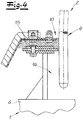
- the Fig. 4 shows a functioning as a false air seal seal 10 of the device according to the invention.
- the seal 10 is provided between the converter 1 and the converter hood 2 for the purpose of avoiding the intrusion of false air into the interior of the converter hood 2.
- the seal 10 or false air seal is firmly connected to the outside of the converter 1.
- the seal 10 has a sealing component 15 which expediently bears against the outside of the associated converter hood wall 4 under prestressing. Upon rotation of the converter 1, the sealing component 15 of the seal 10 thus slides sealingly along the outside of the converter hood 2.
- the voltage applied to the outside of the converter hood 2 sealing material of the sealing component 15 may consist of a preferred embodiment and in the embodiment of mineral wool.
- two hood flaps 11, 12 are arranged in opposite converter hood walls 4 of the converter hood 2, which can be opened for a controlled air supply. By adjusting the opening width, the air supply can be controlled or regulated.
- the hood flaps 11 and 12 is particularly to the Fig. 2 and 5 directed.
- the pivot axes of these hood flaps 11, 12 are preferred and oriented parallel to the longitudinal axis L of the converter drum 6 in the embodiment.
- both hood flaps 11, 12 as well as the other areas of the converter hood walls 4 are cooled by means of the cooled pipe sections 5.
- the hood flaps 11, 12 are pivotable by means of pipe joints 13, which are flowed through by the water vapor-water mixture used for cooling the converter hood walls 4 under pressure.
- the Fig. 5 shows the pipe joints 13 for the larger hood flap 11 of the converter hood 2.
- the pipe joints 13 have Z-shaped pipe joint parts. At the upper end of each Z-shaped pipe joint each pivot 17 is connected.
- a pipe joint 13 and by a Z-shaped pipe joint part is a supply of the pressurized water and over the other opposite pipe joint 13 and the associated Z-shaped pipe joint part takes place a discharge of the water vapor-water mixture.
- Is in Fig. 5 has been clarified by appropriate arrows. - In the Fig.
- hood flaps 11, 12 and the larger hood flap 11 may be connected via a flexible hose 18 with the remaining converter hood 2. This flexible hose 18 is then traversed by the water or by the water vapor-water mixture instead of the pipe joint 13.
Landscapes
- Engineering & Computer Science (AREA)
- Chemical & Material Sciences (AREA)
- Mechanical Engineering (AREA)
- Manufacturing & Machinery (AREA)
- Materials Engineering (AREA)
- Metallurgy (AREA)
- Organic Chemistry (AREA)
- Environmental & Geological Engineering (AREA)
- General Engineering & Computer Science (AREA)
- Waste-Gas Treatment And Other Accessory Devices For Furnaces (AREA)
- Manufacture And Refinement Of Metals (AREA)
- Carbon Steel Or Casting Steel Manufacturing (AREA)
Claims (11)
- Dispositif destiné à la récupération de métaux, notamment à la récupération de cuivre, pourvu d'un convertisseur (1) destiné à recevoir des composés métalliques à transformer, notamment à recevoir des composés de cuivre à transformer, ainsi que d'un capot de convertisseur (2) raccordé sur le convertisseur (1) pour le refroidissement des gaz de combustion chauds s'échappant d'au moins une ouverture de sortie (3) du convertisseur (1), les parois du capot de convertisseur (4) étant formées d'une pluralité tronçons tubulaires (5) assemblés les uns aux autres, caractérisé en ce qu'à travers les tronçons tubulaires (5), un mélange eau-vapeur d'eau sous dépression peut être conduit en tant qu'agent de refroidissement, en ce que le refroidissement du capot de convertisseur (2) comporte au moins un circuit pour le mélange eau-vapeur d'eau et en ce que le mélange eau-vapeur d'eau pour le refroidissement du capot de convertisseur (2) peut se trouver sous une pression de 15 à 85 bar.
- Dispositif selon la revendication 1, le convertisseur (1) comportant un tambour de convertisseur (6) rotatif, sur sa face supérieure, le tambour de convertisseur (6) étant muni d'au moins une ouverture de sortie (3) pour la sortie des gaz de combustion chauds, le capot de convertisseur (2) étant placé au-dessus du tambour de convertisseur (6) ou au-dessus de l'ouverture de sortie (3), et le tambour de convertisseur (6) étant rotatif de préférence indépendamment du capot de convertisseur (2).
- Dispositif selon l'une quelconque des revendications 1 ou 2, derrière le capot de convertisseur (2), dans la direction de circulation des gaz de combustion étant placé un dispositif de chaudière (7) pour le refroidissement ultérieur des gaz de combustion et au moins une partie des parois de chaudière (8) du dispositif de chaudière (7) pouvant être refroidie par un mélange eau-vapeur d'eau (notamment à l'aide d'un mélange eau-vapeur d'eau sous dépression).
- Dispositif selon la revendication 3, le circuit du mélange eau-vapeur d'eau du capot de convertisseur (2) étant ou pouvant être raccordé sur le circuit du mélange eau-vapeur d'eau du dispositif de chaudière (7).
- Dispositif selon l'une quelconque des revendications 1 à 4, le refroidissement du capot de convertisseur (2) étant conçu avec le critère que la température des parois du capot de convertisseur (4) et notamment la température des surfaces intérieures (9) des parois du capot de convertisseur (4) soit inférieure à 310 °C t.
- Dispositif selon la revendication 5, la température des parois du capot de convertisseur (4) et notamment la température des surfaces intérieures (9) des parois du capot de convertisseur (4) s'élevant à de 210 à 310 °C, de préférence à de 210 à 290 °C et de manière particulièrement préférentielle, à de 260 à 285 °C.
- Dispositif selon l'une quelconque des revendications 1 à 6, les tronçons tubulaires (5) d'une paroi du capot de convertisseur (4) étant assemblées les unes aux autres avec le critère qu'il en résulte une surface intérieure (9) plane ou sensiblement plane de la paroi du capot de convertisseur (4).
- Dispositif selon l'une quelconque des revendications 1 à 7, entre le convertisseur (1) et le capot de convertisseur (2) étant placé au moins un joint d'étanchéité (10) ou un joint d'étanchéité à l'air parasite, le joint d'étanchéité (10) étant adjacent (opportunément sous précontrainte) à la face extérieure de la paroi du capot de convertisseur (4) et le joint d'étanchéité (10) étant fixement raccordé sur le convertisseur (1) et le joint d'étanchéité (10) étant de préférence en co-rotation avec le tambour de convertisseur (6) rotatif.
- Dispositif selon l'une quelconque des revendications 1 à 8, dans une paroi du capot de convertisseur (4) ou dans les parois du capot de convertisseur (4) étant présent au moins un clapet de capot (11, 12) susceptible de pivoter dans une position ouverte pour une alimentation d'air contrôlée.
- Dispositif selon la revendication 9, l'au moins un clapet de capot (11) étant susceptible de pivoter au moyen d'articulations tubulaires (13), les articulations tubulaires (13) étant traversées par l'eau ou le mélange eau-vapeur d'eau utilisé pour le refroidissement des parois du capot de convertisseur (4).
- Dispositif selon la revendication 9, l'au moins un clapet de capot (11) étant relié par l'intermédiaire de conduits en tuyaux flexibles (18) avec le reste du capot de convertisseur (2) et les conduits en tuyaux flexibles (18) étant traversés par l'eau ou le mélange eau-vapeur d'eau utilisé pour le refroidissement.
Applications Claiming Priority (2)
| Application Number | Priority Date | Filing Date | Title |
|---|---|---|---|
| DE202013104490U DE202013104490U1 (de) | 2013-10-02 | 2013-10-02 | Vorrichtung zur Metallgewinnung, insbesondere zur Kupfergewinnung |
| DE202013104702U DE202013104702U1 (de) | 2013-10-02 | 2013-10-18 | Vorrichtung zur Metallgewinnung, insbesondere zur Kupfergewinnung |
Publications (2)
| Publication Number | Publication Date |
|---|---|
| EP2857533A1 EP2857533A1 (fr) | 2015-04-08 |
| EP2857533B1 true EP2857533B1 (fr) | 2019-05-08 |
Family
ID=49580005
Family Applications (1)
| Application Number | Title | Priority Date | Filing Date |
|---|---|---|---|
| EP14186110.4A Not-in-force EP2857533B1 (fr) | 2013-10-02 | 2014-09-24 | Dispositif de production de métal, en particulier de cuivre |
Country Status (3)
| Country | Link |
|---|---|
| EP (1) | EP2857533B1 (fr) |
| CL (1) | CL2014002639A1 (fr) |
| DE (2) | DE202013104490U1 (fr) |
Families Citing this family (3)
| Publication number | Priority date | Publication date | Assignee | Title |
|---|---|---|---|---|
| CN109371241B (zh) * | 2018-11-06 | 2020-05-05 | 瑞金盛源环保科技有限责任公司 | 一种阳极泥脱铜装置 |
| CN109468462B (zh) * | 2018-11-06 | 2020-10-02 | 浙江峰邦机械科技有限公司 | 一种阳极泥快速脱铜方法 |
| CN114540570B (zh) * | 2022-01-20 | 2023-02-28 | 中冶南方工程技术有限公司 | 一种转炉余热锅炉烟道 |
Citations (1)
| Publication number | Priority date | Publication date | Assignee | Title |
|---|---|---|---|---|
| GB890869A (en) * | 1960-03-21 | 1962-03-07 | Vorkauf Heinrich | Improvements in and relating to cooled chimneys for converter installations |
Family Cites Families (6)
| Publication number | Priority date | Publication date | Assignee | Title |
|---|---|---|---|---|
| US3625500A (en) * | 1969-11-17 | 1971-12-07 | Nat Steel Corp | Metallurgical furnace fume exhausting |
| SE364732B (fr) * | 1972-02-28 | 1974-03-04 | Boliden Ab | |
| US4396181A (en) * | 1980-11-19 | 1983-08-02 | Inspiration Consolidated Copper Company | Converter for refining liquid metal |
| LU87674A1 (fr) * | 1990-02-07 | 1991-10-08 | Wurth Paul Sa | Hotte a parois refroidies |
| JPH07113111A (ja) * | 1993-10-13 | 1995-05-02 | Nisshin Steel Co Ltd | 金属精錬炉の炉口カバー |
| US6086817A (en) * | 1998-10-16 | 2000-07-11 | Bethlehem Steel Corporation | Off-gas hood for a basic oxygen furnace and method of repair |
-
2013
- 2013-10-02 DE DE202013104490U patent/DE202013104490U1/de not_active Expired - Lifetime
- 2013-10-18 DE DE202013104702U patent/DE202013104702U1/de not_active Expired - Lifetime
-
2014
- 2014-09-24 EP EP14186110.4A patent/EP2857533B1/fr not_active Not-in-force
- 2014-09-30 CL CL2014002639A patent/CL2014002639A1/es unknown
Patent Citations (1)
| Publication number | Priority date | Publication date | Assignee | Title |
|---|---|---|---|---|
| GB890869A (en) * | 1960-03-21 | 1962-03-07 | Vorkauf Heinrich | Improvements in and relating to cooled chimneys for converter installations |
Also Published As
| Publication number | Publication date |
|---|---|
| CL2014002639A1 (es) | 2015-05-04 |
| DE202013104702U1 (de) | 2013-12-19 |
| EP2857533A1 (fr) | 2015-04-08 |
| DE202013104490U1 (de) | 2013-12-05 |
Similar Documents
| Publication | Publication Date | Title |
|---|---|---|
| DE2634281C3 (de) | Düsenplatte zum Ziehen von Glasfasern | |
| DE4020220C2 (de) | Drehbare Halterungsvorrichtung zum Aufbringen eines Schweißüberzugs und Verfahren zum Versehen von aus Rohren bestehenden Stirnwänden mit einem Metallüberzug durch Schweißen | |
| EP2857533B1 (fr) | Dispositif de production de métal, en particulier de cuivre | |
| AT509707B1 (de) | Verfahren zum warmwalzen von stahlbändern und warmwalzstrasse | |
| DE1583208A1 (de) | Blasduese zum Frischen eines Metallbades von oben | |
| EP2551050B1 (fr) | Procédé de soudage de tuyaux à paroi mince par soudage à haute température | |
| WO2011120673A1 (fr) | Procédé de fusion avec parement que l'on peut faire glisser | |
| EP0513740B1 (fr) | Coffrage | |
| EP2127795B1 (fr) | Liaison de soudure | |
| DE602005003216T2 (de) | Vorrichtung zur verarbeitung von hochkorrosiven mitteln | |
| EP2517771A1 (fr) | Tour de lavage | |
| DE102015101356B4 (de) | Roststab mit Kühlmittel-Kanal | |
| DE2406582A1 (de) | Verfahren und vorrichtung zur gewinnung von arsentrioxid aus gasen | |
| DE3625694C2 (fr) | ||
| DE2840293A1 (de) | Plattenwaermetauscher | |
| EP2789405A1 (fr) | Section de refroidissement avec rampe de pulvérisation dotée d'une plaque terminale amovible | |
| DE102006000696B4 (de) | Quenchturm für metallurgische Gase | |
| DE1752650A1 (de) | Verfahren zur Herstellung einer Keramik-Metall-Verschweissung | |
| EP1091181A1 (fr) | Buse d'expansion | |
| DE102005016957A1 (de) | Anlage zum Herstellen von gelöteten Bauteilen | |
| DE102019122012A1 (de) | Flexibles Leitungselement aus Metall | |
| EP3934823B1 (fr) | Dispositif pour refroidir un produit en forme de bande et procédé pour faire fonctionner un tel dispositif | |
| EP3495081A1 (fr) | Procédé pour joindre d'assemblage des pièces accessoires des composants de drainage de toit et des pièces accessoires joint ce faisant | |
| EP2339278B1 (fr) | Utilisation d'un dispositif d'enrichissement de cuivre ou de nickel | |
| DE102007053002A1 (de) | Verbindungsanordnung für den Installationsbereich |
Legal Events
| Date | Code | Title | Description |
|---|---|---|---|
| PUAI | Public reference made under article 153(3) epc to a published international application that has entered the european phase |
Free format text: ORIGINAL CODE: 0009012 |
|
| 17P | Request for examination filed |
Effective date: 20140924 |
|
| AK | Designated contracting states |
Kind code of ref document: A1 Designated state(s): AL AT BE BG CH CY CZ DE DK EE ES FI FR GB GR HR HU IE IS IT LI LT LU LV MC MK MT NL NO PL PT RO RS SE SI SK SM TR |
|
| AX | Request for extension of the european patent |
Extension state: BA ME |
|
| R17P | Request for examination filed (corrected) |
Effective date: 20150821 |
|
| RBV | Designated contracting states (corrected) |
Designated state(s): AL AT BE BG CH CY CZ DE DK EE ES FI FR GB GR HR HU IE IS IT LI LT LU LV MC MK MT NL NO PL PT RO RS SE SI SK SM TR |
|
| 17Q | First examination report despatched |
Effective date: 20160314 |
|
| STAA | Information on the status of an ep patent application or granted ep patent |
Free format text: STATUS: EXAMINATION IS IN PROGRESS |
|
| GRAP | Despatch of communication of intention to grant a patent |
Free format text: ORIGINAL CODE: EPIDOSNIGR1 |
|
| STAA | Information on the status of an ep patent application or granted ep patent |
Free format text: STATUS: GRANT OF PATENT IS INTENDED |
|
| INTG | Intention to grant announced |
Effective date: 20180416 |
|
| GRAS | Grant fee paid |
Free format text: ORIGINAL CODE: EPIDOSNIGR3 |
|
| 19U | Interruption of proceedings before grant |
Effective date: 20170501 |
|
| 19W | Proceedings resumed before grant after interruption of proceedings |
Effective date: 20190301 |
|
| GRAJ | Information related to disapproval of communication of intention to grant by the applicant or resumption of examination proceedings by the epo deleted |
Free format text: ORIGINAL CODE: EPIDOSDIGR1 |
|
| GRAL | Information related to payment of fee for publishing/printing deleted |
Free format text: ORIGINAL CODE: EPIDOSDIGR3 |
|
| GRAP | Despatch of communication of intention to grant a patent |
Free format text: ORIGINAL CODE: EPIDOSNIGR1 |
|
| GRAS | Grant fee paid |
Free format text: ORIGINAL CODE: EPIDOSNIGR3 |
|
| GRAA | (expected) grant |
Free format text: ORIGINAL CODE: 0009210 |
|
| STAA | Information on the status of an ep patent application or granted ep patent |
Free format text: STATUS: THE PATENT HAS BEEN GRANTED |
|
| INTG | Intention to grant announced |
Effective date: 20190313 |
|
| RAP1 | Party data changed (applicant data changed or rights of an application transferred) |
Owner name: OSCHATZ ENERGY AND ENVIRONMENT GMBH |
|
| AK | Designated contracting states |
Kind code of ref document: B1 Designated state(s): AL AT BE BG CH CY CZ DE DK EE ES FI FR GB GR HR HU IE IS IT LI LT LU LV MC MK MT NL NO PL PT RO RS SE SI SK SM TR |
|
| REG | Reference to a national code |
Ref country code: GB Ref legal event code: FG4D Free format text: NOT ENGLISH |
|
| REG | Reference to a national code |
Ref country code: CH Ref legal event code: EP Ref country code: AT Ref legal event code: REF Ref document number: 1130222 Country of ref document: AT Kind code of ref document: T Effective date: 20190515 |
|
| REG | Reference to a national code |
Ref country code: DE Ref legal event code: R096 Ref document number: 502014011648 Country of ref document: DE Ref country code: IE Ref legal event code: FG4D Free format text: LANGUAGE OF EP DOCUMENT: GERMAN |
|
| REG | Reference to a national code |
Ref country code: NL Ref legal event code: MP Effective date: 20190508 |
|
| REG | Reference to a national code |
Ref country code: LT Ref legal event code: MG4D |
|
| PG25 | Lapsed in a contracting state [announced via postgrant information from national office to epo] |
Ref country code: HR Free format text: LAPSE BECAUSE OF FAILURE TO SUBMIT A TRANSLATION OF THE DESCRIPTION OR TO PAY THE FEE WITHIN THE PRESCRIBED TIME-LIMIT Effective date: 20190508 Ref country code: AL Free format text: LAPSE BECAUSE OF FAILURE TO SUBMIT A TRANSLATION OF THE DESCRIPTION OR TO PAY THE FEE WITHIN THE PRESCRIBED TIME-LIMIT Effective date: 20190508 Ref country code: NO Free format text: LAPSE BECAUSE OF FAILURE TO SUBMIT A TRANSLATION OF THE DESCRIPTION OR TO PAY THE FEE WITHIN THE PRESCRIBED TIME-LIMIT Effective date: 20190808 Ref country code: PT Free format text: LAPSE BECAUSE OF FAILURE TO SUBMIT A TRANSLATION OF THE DESCRIPTION OR TO PAY THE FEE WITHIN THE PRESCRIBED TIME-LIMIT Effective date: 20190908 Ref country code: SE Free format text: LAPSE BECAUSE OF FAILURE TO SUBMIT A TRANSLATION OF THE DESCRIPTION OR TO PAY THE FEE WITHIN THE PRESCRIBED TIME-LIMIT Effective date: 20190508 Ref country code: FI Free format text: LAPSE BECAUSE OF FAILURE TO SUBMIT A TRANSLATION OF THE DESCRIPTION OR TO PAY THE FEE WITHIN THE PRESCRIBED TIME-LIMIT Effective date: 20190508 Ref country code: ES Free format text: LAPSE BECAUSE OF FAILURE TO SUBMIT A TRANSLATION OF THE DESCRIPTION OR TO PAY THE FEE WITHIN THE PRESCRIBED TIME-LIMIT Effective date: 20190508 Ref country code: NL Free format text: LAPSE BECAUSE OF FAILURE TO SUBMIT A TRANSLATION OF THE DESCRIPTION OR TO PAY THE FEE WITHIN THE PRESCRIBED TIME-LIMIT Effective date: 20190508 Ref country code: LT Free format text: LAPSE BECAUSE OF FAILURE TO SUBMIT A TRANSLATION OF THE DESCRIPTION OR TO PAY THE FEE WITHIN THE PRESCRIBED TIME-LIMIT Effective date: 20190508 |
|
| PG25 | Lapsed in a contracting state [announced via postgrant information from national office to epo] |
Ref country code: BG Free format text: LAPSE BECAUSE OF FAILURE TO SUBMIT A TRANSLATION OF THE DESCRIPTION OR TO PAY THE FEE WITHIN THE PRESCRIBED TIME-LIMIT Effective date: 20190808 Ref country code: LV Free format text: LAPSE BECAUSE OF FAILURE TO SUBMIT A TRANSLATION OF THE DESCRIPTION OR TO PAY THE FEE WITHIN THE PRESCRIBED TIME-LIMIT Effective date: 20190508 Ref country code: RS Free format text: LAPSE BECAUSE OF FAILURE TO SUBMIT A TRANSLATION OF THE DESCRIPTION OR TO PAY THE FEE WITHIN THE PRESCRIBED TIME-LIMIT Effective date: 20190508 Ref country code: GR Free format text: LAPSE BECAUSE OF FAILURE TO SUBMIT A TRANSLATION OF THE DESCRIPTION OR TO PAY THE FEE WITHIN THE PRESCRIBED TIME-LIMIT Effective date: 20190809 |
|
| PG25 | Lapsed in a contracting state [announced via postgrant information from national office to epo] |
Ref country code: EE Free format text: LAPSE BECAUSE OF FAILURE TO SUBMIT A TRANSLATION OF THE DESCRIPTION OR TO PAY THE FEE WITHIN THE PRESCRIBED TIME-LIMIT Effective date: 20190508 Ref country code: DK Free format text: LAPSE BECAUSE OF FAILURE TO SUBMIT A TRANSLATION OF THE DESCRIPTION OR TO PAY THE FEE WITHIN THE PRESCRIBED TIME-LIMIT Effective date: 20190508 Ref country code: CZ Free format text: LAPSE BECAUSE OF FAILURE TO SUBMIT A TRANSLATION OF THE DESCRIPTION OR TO PAY THE FEE WITHIN THE PRESCRIBED TIME-LIMIT Effective date: 20190508 Ref country code: RO Free format text: LAPSE BECAUSE OF FAILURE TO SUBMIT A TRANSLATION OF THE DESCRIPTION OR TO PAY THE FEE WITHIN THE PRESCRIBED TIME-LIMIT Effective date: 20190508 Ref country code: SK Free format text: LAPSE BECAUSE OF FAILURE TO SUBMIT A TRANSLATION OF THE DESCRIPTION OR TO PAY THE FEE WITHIN THE PRESCRIBED TIME-LIMIT Effective date: 20190508 |
|
| REG | Reference to a national code |
Ref country code: DE Ref legal event code: R097 Ref document number: 502014011648 Country of ref document: DE |
|
| PG25 | Lapsed in a contracting state [announced via postgrant information from national office to epo] |
Ref country code: PL Free format text: LAPSE BECAUSE OF FAILURE TO SUBMIT A TRANSLATION OF THE DESCRIPTION OR TO PAY THE FEE WITHIN THE PRESCRIBED TIME-LIMIT Effective date: 20190508 Ref country code: SM Free format text: LAPSE BECAUSE OF FAILURE TO SUBMIT A TRANSLATION OF THE DESCRIPTION OR TO PAY THE FEE WITHIN THE PRESCRIBED TIME-LIMIT Effective date: 20190508 Ref country code: IT Free format text: LAPSE BECAUSE OF FAILURE TO SUBMIT A TRANSLATION OF THE DESCRIPTION OR TO PAY THE FEE WITHIN THE PRESCRIBED TIME-LIMIT Effective date: 20190508 |
|
| PLBE | No opposition filed within time limit |
Free format text: ORIGINAL CODE: 0009261 |
|
| STAA | Information on the status of an ep patent application or granted ep patent |
Free format text: STATUS: NO OPPOSITION FILED WITHIN TIME LIMIT |
|
| PG25 | Lapsed in a contracting state [announced via postgrant information from national office to epo] |
Ref country code: TR Free format text: LAPSE BECAUSE OF FAILURE TO SUBMIT A TRANSLATION OF THE DESCRIPTION OR TO PAY THE FEE WITHIN THE PRESCRIBED TIME-LIMIT Effective date: 20190508 |
|
| 26N | No opposition filed |
Effective date: 20200211 |
|
| PG25 | Lapsed in a contracting state [announced via postgrant information from national office to epo] |
Ref country code: SI Free format text: LAPSE BECAUSE OF FAILURE TO SUBMIT A TRANSLATION OF THE DESCRIPTION OR TO PAY THE FEE WITHIN THE PRESCRIBED TIME-LIMIT Effective date: 20190508 Ref country code: MC Free format text: LAPSE BECAUSE OF FAILURE TO SUBMIT A TRANSLATION OF THE DESCRIPTION OR TO PAY THE FEE WITHIN THE PRESCRIBED TIME-LIMIT Effective date: 20190508 |
|
| REG | Reference to a national code |
Ref country code: CH Ref legal event code: PL |
|
| PG25 | Lapsed in a contracting state [announced via postgrant information from national office to epo] |
Ref country code: LU Free format text: LAPSE BECAUSE OF NON-PAYMENT OF DUE FEES Effective date: 20190924 Ref country code: LI Free format text: LAPSE BECAUSE OF NON-PAYMENT OF DUE FEES Effective date: 20190930 Ref country code: IE Free format text: LAPSE BECAUSE OF NON-PAYMENT OF DUE FEES Effective date: 20190924 Ref country code: CH Free format text: LAPSE BECAUSE OF NON-PAYMENT OF DUE FEES Effective date: 20190930 |
|
| REG | Reference to a national code |
Ref country code: BE Ref legal event code: MM Effective date: 20190930 |
|
| PG25 | Lapsed in a contracting state [announced via postgrant information from national office to epo] |
Ref country code: BE Free format text: LAPSE BECAUSE OF NON-PAYMENT OF DUE FEES Effective date: 20190930 |
|
| GBPC | Gb: european patent ceased through non-payment of renewal fee |
Effective date: 20190924 |
|
| PG25 | Lapsed in a contracting state [announced via postgrant information from national office to epo] |
Ref country code: FR Free format text: LAPSE BECAUSE OF NON-PAYMENT OF DUE FEES Effective date: 20190930 Ref country code: GB Free format text: LAPSE BECAUSE OF NON-PAYMENT OF DUE FEES Effective date: 20190924 |
|
| REG | Reference to a national code |
Ref country code: AT Ref legal event code: MM01 Ref document number: 1130222 Country of ref document: AT Kind code of ref document: T Effective date: 20190924 |
|
| PG25 | Lapsed in a contracting state [announced via postgrant information from national office to epo] |
Ref country code: AT Free format text: LAPSE BECAUSE OF NON-PAYMENT OF DUE FEES Effective date: 20190924 |
|
| PG25 | Lapsed in a contracting state [announced via postgrant information from national office to epo] |
Ref country code: CY Free format text: LAPSE BECAUSE OF FAILURE TO SUBMIT A TRANSLATION OF THE DESCRIPTION OR TO PAY THE FEE WITHIN THE PRESCRIBED TIME-LIMIT Effective date: 20190508 |
|
| PG25 | Lapsed in a contracting state [announced via postgrant information from national office to epo] |
Ref country code: IS Free format text: LAPSE BECAUSE OF FAILURE TO SUBMIT A TRANSLATION OF THE DESCRIPTION OR TO PAY THE FEE WITHIN THE PRESCRIBED TIME-LIMIT Effective date: 20190908 |
|
| PG25 | Lapsed in a contracting state [announced via postgrant information from national office to epo] |
Ref country code: MT Free format text: LAPSE BECAUSE OF FAILURE TO SUBMIT A TRANSLATION OF THE DESCRIPTION OR TO PAY THE FEE WITHIN THE PRESCRIBED TIME-LIMIT Effective date: 20190508 Ref country code: HU Free format text: LAPSE BECAUSE OF FAILURE TO SUBMIT A TRANSLATION OF THE DESCRIPTION OR TO PAY THE FEE WITHIN THE PRESCRIBED TIME-LIMIT; INVALID AB INITIO Effective date: 20140924 |
|
| PG25 | Lapsed in a contracting state [announced via postgrant information from national office to epo] |
Ref country code: MK Free format text: LAPSE BECAUSE OF FAILURE TO SUBMIT A TRANSLATION OF THE DESCRIPTION OR TO PAY THE FEE WITHIN THE PRESCRIBED TIME-LIMIT Effective date: 20190508 |
|
| PGFP | Annual fee paid to national office [announced via postgrant information from national office to epo] |
Ref country code: DE Payment date: 20220922 Year of fee payment: 9 |
|
| REG | Reference to a national code |
Ref country code: DE Ref legal event code: R119 Ref document number: 502014011648 Country of ref document: DE |
|
| PG25 | Lapsed in a contracting state [announced via postgrant information from national office to epo] |
Ref country code: DE Free format text: LAPSE BECAUSE OF NON-PAYMENT OF DUE FEES Effective date: 20240403 |