EP2857621A1 - Charnière pour un élément de meuble et meuble - Google Patents
Charnière pour un élément de meuble et meuble Download PDFInfo
- Publication number
- EP2857621A1 EP2857621A1 EP14187250.7A EP14187250A EP2857621A1 EP 2857621 A1 EP2857621 A1 EP 2857621A1 EP 14187250 A EP14187250 A EP 14187250A EP 2857621 A1 EP2857621 A1 EP 2857621A1
- Authority
- EP
- European Patent Office
- Prior art keywords
- hinge
- lever
- guide
- further lever
- furniture
- Prior art date
- Legal status (The legal status is an assumption and is not a legal conclusion. Google has not performed a legal analysis and makes no representation as to the accuracy of the status listed.)
- Granted
Links
Images


Classifications
-
- E—FIXED CONSTRUCTIONS
- E05—LOCKS; KEYS; WINDOW OR DOOR FITTINGS; SAFES
- E05D—HINGES OR SUSPENSION DEVICES FOR DOORS, WINDOWS OR WINGS
- E05D3/00—Hinges with pins
- E05D3/06—Hinges with pins with two or more pins
- E05D3/12—Hinges with pins with two or more pins with two parallel pins and one arm
-
- E—FIXED CONSTRUCTIONS
- E05—LOCKS; KEYS; WINDOW OR DOOR FITTINGS; SAFES
- E05F—DEVICES FOR MOVING WINGS INTO OPEN OR CLOSED POSITION; CHECKS FOR WINGS; WING FITTINGS NOT OTHERWISE PROVIDED FOR, CONCERNED WITH THE FUNCTIONING OF THE WING
- E05F5/00—Braking devices, e.g. checks; Stops; Buffers
- E05F5/006—Braking devices, e.g. checks; Stops; Buffers for hinges having a cup-shaped fixing part, e.g. for attachment to cabinets or furniture
-
- E—FIXED CONSTRUCTIONS
- E05—LOCKS; KEYS; WINDOW OR DOOR FITTINGS; SAFES
- E05D—HINGES OR SUSPENSION DEVICES FOR DOORS, WINDOWS OR WINGS
- E05D11/00—Additional features or accessories of hinges
- E05D11/10—Devices for preventing movement between relatively-movable hinge parts
-
- E—FIXED CONSTRUCTIONS
- E05—LOCKS; KEYS; WINDOW OR DOOR FITTINGS; SAFES
- E05D—HINGES OR SUSPENSION DEVICES FOR DOORS, WINDOWS OR WINGS
- E05D3/00—Hinges with pins
- E05D3/06—Hinges with pins with two or more pins
- E05D3/16—Hinges with pins with two or more pins with seven parallel pins and four arms
-
- E—FIXED CONSTRUCTIONS
- E05—LOCKS; KEYS; WINDOW OR DOOR FITTINGS; SAFES
- E05Y—INDEXING SCHEME ASSOCIATED WITH SUBCLASSES E05D AND E05F, RELATING TO CONSTRUCTION ELEMENTS, ELECTRIC CONTROL, POWER SUPPLY, POWER SIGNAL OR TRANSMISSION, USER INTERFACES, MOUNTING OR COUPLING, DETAILS, ACCESSORIES, AUXILIARY OPERATIONS NOT OTHERWISE PROVIDED FOR, APPLICATION THEREOF
- E05Y2201/00—Constructional elements; Accessories therefor
- E05Y2201/20—Brakes; Disengaging means; Holders; Stops; Valves; Accessories therefor
- E05Y2201/21—Brakes
-
- E—FIXED CONSTRUCTIONS
- E05—LOCKS; KEYS; WINDOW OR DOOR FITTINGS; SAFES
- E05Y—INDEXING SCHEME ASSOCIATED WITH SUBCLASSES E05D AND E05F, RELATING TO CONSTRUCTION ELEMENTS, ELECTRIC CONTROL, POWER SUPPLY, POWER SIGNAL OR TRANSMISSION, USER INTERFACES, MOUNTING OR COUPLING, DETAILS, ACCESSORIES, AUXILIARY OPERATIONS NOT OTHERWISE PROVIDED FOR, APPLICATION THEREOF
- E05Y2201/00—Constructional elements; Accessories therefor
- E05Y2201/20—Brakes; Disengaging means; Holders; Stops; Valves; Accessories therefor
- E05Y2201/214—Disengaging means
-
- E—FIXED CONSTRUCTIONS
- E05—LOCKS; KEYS; WINDOW OR DOOR FITTINGS; SAFES
- E05Y—INDEXING SCHEME ASSOCIATED WITH SUBCLASSES E05D AND E05F, RELATING TO CONSTRUCTION ELEMENTS, ELECTRIC CONTROL, POWER SUPPLY, POWER SIGNAL OR TRANSMISSION, USER INTERFACES, MOUNTING OR COUPLING, DETAILS, ACCESSORIES, AUXILIARY OPERATIONS NOT OTHERWISE PROVIDED FOR, APPLICATION THEREOF
- E05Y2201/00—Constructional elements; Accessories therefor
- E05Y2201/20—Brakes; Disengaging means; Holders; Stops; Valves; Accessories therefor
- E05Y2201/262—Type of motion, e.g. braking
- E05Y2201/264—Type of motion, e.g. braking linear
-
- E—FIXED CONSTRUCTIONS
- E05—LOCKS; KEYS; WINDOW OR DOOR FITTINGS; SAFES
- E05Y—INDEXING SCHEME ASSOCIATED WITH SUBCLASSES E05D AND E05F, RELATING TO CONSTRUCTION ELEMENTS, ELECTRIC CONTROL, POWER SUPPLY, POWER SIGNAL OR TRANSMISSION, USER INTERFACES, MOUNTING OR COUPLING, DETAILS, ACCESSORIES, AUXILIARY OPERATIONS NOT OTHERWISE PROVIDED FOR, APPLICATION THEREOF
- E05Y2900/00—Application of doors, windows, wings or fittings thereof
- E05Y2900/20—Application of doors, windows, wings or fittings thereof for furniture, e.g. cabinets
Definitions
- hinges for the pivotable storage of furniture parts on a carcass. These can comprise an attachable to the body stop or hinge part and a fixable on the movable furniture part hinge part. With the mutually pivotable stop parts furniture parts such as a door or a flap can be moved via a hinged mechanism provided with the hinge.
- double link or four-joint hinges for example, two articulated levers or articulated arms are provided on the hinge.
- Object of the present invention is to make the above-mentioned arrangements with extended functionality compact, in particular occurring malpositions of hinge parts are to be fixed automatically in the hinge mode.
- the invention relates to a hinge for a movable furniture part, which is receivable on the hinge on a body of a piece of furniture, in particular furniture hinge for a door or flap, wherein the hinge has a attachable to the body first stop member, which via a hinge mechanism with a attachable to the movable furniture part second stop member is pivotally connected, wherein the hinge mechanism mounted on hinge axes articulated lever comprises, and wherein a force acting on a damper assembly of the hinge further lever is present, which is pivotally received via a separate axis to the hinge axis and at a proper pivoting movement of the hinge is engaged at times with a guide portion on the hinge, wherein during normal operation of the hinge, the further lever assumes a predetermined standby position before a coupling operation, from which einkup the further lever on the guide portion pelt.
- a matched to the other lever control section is designed such that the other lever on the hinge from a pivotal position, which differs from the predetermined ready position before the engagement, in the intended pivotal movement of the hinge with the Actuator cooperates, so that the actuating portion forcibly displaced the further lever in the engaged state.
- the other lever is thus functionally correct on the hinge in the engaged position on the guide portion of the hinge can be brought in non-control positions of the other lever on the control section.
- the invention is advantageous in terms of the function of the damper assembly.
- the further pivotally mounted lever is temporarily engaged in a complete intended pivotal movement of the hinge with a guide portion on the hinge, wherein the further lever acts on the damper assembly of the hinge.
- the damper assembly of the hinge is used in particular to achieve a damped or braked movement in an end position of the pivoting operation carried out with the hinge in a proper pivoting movement of the hinge. This can be avoided in the furniture-mounted state of the hinge in particular an undesirable strong slamming of the movable furniture part, in particular an unpleasant surcharge noise or damage to the furniture part and the body.
- the actuation of the damper assembly in the interaction of the other lever with the guide portion is advantageously always on the same point of the pivoting movement of the furniture part or at an always identical pivot position of the hinge on the way to an end position of the pivoting movement possible with the hinge.
- the interaction of the other lever with the guide portion can be realized very compact or compact.
- the further lever and the guide section can be provided in areas which are freely available anyway with known corresponding hinges. These areas are preferably in the interior of the hinge, not or hardly visible from the outside. In this way, in the case of an arrangement according to the invention, a desired appearance or a preferred exterior design can be realized without difficulty.
- the hinge may alternatively comprise instead of the damper assembly or in addition to this an actuator, so that further lever is temporarily engaged in a complete intended pivotal movement of the hinge with a guide portion on the hinge, wherein the further lever acts on the actuator of the hinge.
- An actuator is generally understood to mean an element that converts an input to a different output to produce a desired action or effect.
- Aktor850ien example inductively operating electric motors, hydraulic or pneumatic actuators, cylinders, electrochemical or electro-mechanical actuators, piezo actuators are conceivable.
- an electric motor can be operated or controlled via the interaction of the further lever with the guide section.
- a closing and / or opening movement of the movable furniture part can be influenced.
- actuator for example, a locking or latching of the movable furniture part, in particular in a closed end position via the actuator.
- the meshing or engagement can be done for example by means of a catching or threading mechanism.
- the guide section for example, have a slotted guide for the other lever. A portion of the other lever is this exactly matched in shape to the slide guide.
- the system may also be considered as a kind of forced control of the further lever through the guide section.
- the further lever remains unmoved in the non-engaged state and is pivoted in the coupling state.
- the further lever is pivotally received via a separate axis to the hinge axes.
- the further lever may be present, for example, on a stop member in the region between two existing hinge axes.
- an abutment portion of the further lever is present, which is engageable with the guide portion, wherein the adjusting portion comprises a matched to the abutment portion guide edge, which is oriented obliquely in a direction of movement of the abutment portion.
- the adjusting section is provided on a component or lever on which the guide section is formed.
- an extension of the adjusting section is adapted to at least one substantial extension of the guide section.
- the adjusting portion and the guide portion cooperate advantageous.
- the adjusting portion comprises a passage for the abutment portion, wherein the passage has opposite inclined surfaces.
- the adjusting section preferably has oblique surfaces tapering in the direction of passage toward the guide section. This also increases the functionality of the adjusting section.
- the further lever and the guide section are matched to one another in such a way, a coupling state between the other lever and the Guide section that adjusts to a final pivoting movement of the hinge in an end position, in a pivotal movement of the hinge from the end position, picking up.
- the engagement of the further lever on the guide portion and the maintenance of the EinkupplungsSprs takes place over a part or a phase of the entire pivoting movement possible with the hinge.
- this phase describes a phase before reaching an end point of the pivoting movement, that is to say the point of engagement, up to the associated end point, without reversing the direction of movement.
- a decoupled or uncoupled situation of the further lever and the guide section is again achieved during a return movement of the hinge, for example when the movable furniture part is opened relative to the carcass.
- the damper assembly and the actuator is brought back into an initial state according to the action of the lever.
- the damper arrangement or the actuator of the hinge is then operated again.
- the further lever is adapted to act on a portion of a component which is present on the attachable to the body first stop member.
- the damper or an actuator can be accommodated on the attached to the body abutment part, which is advantageous for structural reasons or for reasons of space usually.
- damper arrangement or the actuator is present on the stop member, which is accommodated on the body.
- the guide section is received between two hinge axes of the hinge.
- the guide section may in particular advantageously be present between a positionally fixed joint axis on a stop part and a joint axis which is moved along during the pivoting process.
- the guide section can be accommodated in a particularly space-saving.
- the guide portion comprises a raised or recessed to adjacent areas guide track, which is designed to be tuned for the temporary engagement with an engagement portion of the other lever.
- the guideway is configured as a guide groove or as a guide channel.
- a protruding or raised part such. B. engage an engagement nose on the other lever in the guide groove and possibly moved in Einkupplungsschreib along the guide groove.
- the guide portion has an engagement portion which engages in the coupling state in a guide groove on the other lever.
- the guide section is present in such a way that the guide section is moved along in the case of an intended pivoting movement of the hinge.
- the guide section always moves when the pivoting movement takes place.
- the guide portion may be provided for example on a toggle lever, for example in one piece with this or as an additional part.
- the further lever is pivotally mounted on one of the stop members.
- the further lever is designed as a two-armed lever.
- the other lever can interact with one end with the guide portion and with the other end with the damper assembly and the actuator.
- the further lever can be viewed in the longitudinal direction, in particular in the region of its axis have a bend or bend.
- the further lever and the damper assembly are arranged on the same stop member.
- the action on the damper can be done by the lever in close proximity.
- the further lever and the actuator can be arranged on the same stop member.
- the hinge is designed as a universal joint hinge.
- the universal joint hinge can be particularly stable and designed for different maximum bridgeable angular ranges of the pivoting movement.
- the joint mechanism of a universal joint hinge may in particular comprise a first and a second cross lever and a first and a second connecting lever, wherein the first connecting lever via a first joint on the first stop member and a second joint to the first cross lever is connected via a third stop-side cross-link is received on the second stop member and the second connecting lever is connected via a fourth joint on the second stop member and a fifth joint with the second cross lever, which is received via a sixth stop-side cross lever joint on the first stop member and wherein the two cross levers articulated to each other via a universal joint are. All levers can be pivoted at the same time by an associated one of the aforementioned joints in a joint movement.
- the guide portion is provided between the universal joint and a stop-side cross lever joint and is mitbewegbar according to the movement of one of the two cross levers in an executable with the hinge pivoting movement.
- the hinge is designed as a wide-angle hinge.
- a wide-angle hinge allows in the use state particularly wide opening or pivoting of the movable furniture part relative to a closed position on the body. In particular, larger swing angles up to more than 160 degrees can be realized.
- the invention also relates to a piece of furniture with a movable furniture part, which is posted on a body of the piece of furniture, in particular with a door or flap, wherein the piece of furniture has a hinge according to one of the abovementioned embodiments. This makes it possible to realize the advantages already explained above on the furniture.
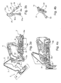
- the hinge 1 is designed as a so-called wide-angle or universal joint hinge.
- the hinge 1 comprises a carcass hinge part 2 which can be attached to a carcass K of a furniture part, and a door hinge part or a hinge cup or a movable furniture part hinge part 3, which on a movably received on the hinge 1 on the body furniture part M, such as a door or a flap, attachable.
- the body K and the furniture part M are in FIG. 3a purely schematized partially indicated.
- the hinge parts 2 and 3 can in each case be fastened on the inside of the body or on the movable furniture part, in particular via screws or via quick-fastening means, in particular without tools.
- the two hinge parts 2 and 3 are connected to each other by four hinge arms 4 to 7 via a hinge mechanism to each other pivotally.
- the articulated arms comprise a first cross arm 4 and a second cross arm 5 and a first connecting arm 6 and a second connecting arm 7.
- the hinge mechanism seven pivot joints 8 to 14, which are hereinafter referred to as the first to sixth joint and as a universal joint.
- the first joint 8 is used for pivotally receiving the first connecting arm 6 on the body hinge part 2, wherein the connecting arm 6 is connected via a second joint 9 with the first cross arm 4, which in turn is pivotally received on the furniture part hinge part 3 via a third joint 10.
- the furniture part hinge part 3 is also articulated about a fourth joint 11 of the second connecting arm 7 and pivotally connected via a fifth joint 12 with the second cross arm 5.
- the second cross arm 5 is also accommodated on the carcass hinge part 2 via a sixth joint 13 articulated on the carcass hinge part 2.
- the two cross arms 4, 5 are hinged together via a universal joint 14. All joint axes of the joints 8 to 14 are parallel or perpendicular to the cutting plane of the FIGS. 3a, 4a ,
- the hinge 1 hinge mechanism can in the mounted state on the furniture thus the movable furniture part M from its closed to the body K position or the end position of the hinge 1 according to FIG. 4a in a maximum wide pivoted open position of the furniture part or in the end position of the hinge 1 according to FIG. 2 be brought, which corresponds to a maximum tilt angle of over 160 degrees. Therefore, the hinge 1 is also referred to as a wide-angle hinge.
- the carcass hinge part 2 comprises an inner mounting part 15 and a fitting part 16 which can be placed thereon or above.
- the carcass hinge part 2 also comprises for adjusting the mounted hinge 1 adjusting means comprising an adjusting screw 17 and an adjusting element 18.
- the z. B. is designed as a fluid damper, a damper assembly integrated, which is on or adjustable in their damper characteristics.
- the damper 19 comprises a housing 19a, in which a non-apparent piston is slidably received, with which a protruding from the housing 19a piston rod 19b is connected.
- An operating bracket 20 is externally connected to the housing 19a via clamping jaws 20a.
- the piston rod 19b is connected to the lower end of the adjusting screw 17.
- a connecting pin 21 serves to connect the mounting part 15 and the attachment part 16.
- a control which comprises a connected to the housing 19 a operating lever 22, the pivotable via a bore 23 in the operating lever 22, a bore 25 in the attachment part 16 and the bores 23 and 25 by cross-axis pin 24 is mounted on the mounting part 16, with a pivot axis which runs parallel to the joint axes 8 to 14.
- the operating lever 22 is designed as a two-armed lever.
- the operating lever 22 is pivotally connected at its end facing the attachment part 16 via an axle pin 26 with the operating bracket 20 via a further bore 28 at the end on the operating lever 22 and a bore 27 in the operating bracket 20.
- the operating lever 22 is provided with an engagement section in the form of a profiling, here in the form of a lug 29 protruding laterally toward the longitudinal extension, which interacts with a guide section 30 on a guide lever 31 in phases or in phases. and disengageable.
- the guide portion 30 in the guide lever 31 includes a slightly curved groove 30 a, which in particular according to the FIGS. 3b and 4b in the central longitudinal section through the guide lever 31 can be seen, with a groove depth in about the height of the protruding nose 29 corresponds.
- the groove 30a ends closed in the guide lever 31, wherein for safe and smooth engagement and disengagement of the nose 29 with the guide portion 30, the groove 30a widens at its open end via an expanding or funnel-shaped from the side threading 30b.
- the nose is designed for a clean unwinding and threading or sliding in the groove 30a in section on one side convex and half flat.
- an open end slot instead of the guide groove, an open end slot, an incision, a slotted guide, etc. may be formed.
- the guide lever 31 has at the end in each case bores 31a, 31b, via which the guide lever 31 between the axle pins 13a and 14a and the corresponding joints 13 and 14 is clamped.
- the guide lever 31 is moved according to the moving during the pivoting operation with the hinge part 1 of the second cross arm 5.
- FIGS. 3a and 4a clearly, according to which the guide lever 31 in FIG. 3a in accordance with the intermediate position shown in its longitudinal orientation is approximately perpendicular to the longitudinal extent of the body hinge part 2 and in FIG. 4a is tilted at an end position of the pivot mechanism with the hinge 1 to the right by about 45 degrees.
- the guide portion or the guide lever 31 and the other lever or the actuating lever 22 may be present at a different location in the hinge 1 and in other hinges.
- the hinge 1 also has an intake assembly 32 integrated in the first cross arm 4, which in accordance with a last portion of the pivotal movement before reaching a closed position FIG. 4a via two integrated coil springs 33, 34 and a pressure plate 35 upon reaching a predefinable pivot position of the hinge 1 this automatically in the closed end position according to FIG. 4a presses or pulls, with the necessary closing force by the two biased coil springs 33, 34 is realized.
- the coil springs 33, 34 act after lifting a blockage of the feeder assembly 32, which z. B.
- the feeder assembly 32 is held on the cross arm 4 via two plug pins 36, 37.
- the feeder assembly 32 Upon reopening of the furniture part M mounted on the furniture hinge part 3 relative to the body K, the feeder assembly 32 is brought back into its biased position ( FIG. 1, 2 . 3a ) And held in this until the return to a return movement by pivoting the hinge 1 when closing the relevant furniture part, the predetermined retraction position is reached. Accordingly, the damper assembly 19 is again in the ready position according to FIG. 1, 2 or 3a brought by pushing back the housing 19a in the standby position by the action of the corresponding when opening the furniture part M penetrateschwenkenden actuating lever 22nd
- FIG. 6 shows a hinge 1 according to the invention to the hinge 1, which corresponds in the basic function substantially according to the hinge 1 and is constructed accordingly.
- the hinge 38 comprises the same basic components as the hinge 1, in particular a carcass hinge part 2 on the body K, a furniture hinge part 3 on the furniture part M, cross arms 4, 5, connecting arms 6, 7, a damper 19 with a piston rod 19 b, a Operating bracket 20 and a guide portion 30 on the hinge 38.
- the hinge 38 is explained in particular with respect to the differences from the hinge 1.
- FIG. 6 is the hinge 38 in a state near an end position of the hinge 38 with the furniture closed part.
- a disengaged state of a guide lever 39 and an interacting with this control lever 40 is shown.
- the guide lever 39 and the operating lever 40 function in normal operation according to the interaction of the guide lever 31 with the operating lever 22 according to the hinge 1 and are therefore closely approximated in their basic shape of the guide lever 31 and the operating lever 22 or arranged accordingly.
- the guide lever 39 has for threading a front End region 41 of the operating lever 40 in a gate or groove 42 on the guide lever 39, a guide surface 43 which is formed over the longitudinal extent of the groove 42 at its end region 41 directed edge.
- the guide surface 43 is formed or tuned to the moving with the pivoting of the operating lever 40 end portion 41 so that at a pivot position of the operating lever 40 according to the direction P3 before a coupling operation of the operating lever 40 on the guide lever 39, wherein the pivot position of a given functionally correct standby position distinguishes the end portion 41 of the operating lever 40 and thus this even in the functionally correct position to the guide lever 39 and further into the correct Einkuppel ein of operating lever 40 and guide lever 39 brings.
- the orientation or the course and / or the shape of the guide surface 43 may be formed on a corresponding mating surface cooperating with the end portion 41 of the operating lever 40 for a smooth or sliding cooperation of operating lever 40 and guide lever 39 to ensure a smooth hinge movement ,
- the guide surface 43 may be designed, for example, at the front edge 43 a such that the end portion 41 of the operating lever 40 can engage with significant resistance in the groove 42, when a hinge movement of the hinge 38 takes place, in which the operating lever 40 engages the guide lever 39.
- a damper 19 is triggered on the hinge 38, so that the closing movement of the movable furniture part, not shown, takes place gently.
- FIG. 6 shows the operating lever 40 in the disengaged state from the guide lever 39 and an existing gate with the groove 42nd
Landscapes
- Engineering & Computer Science (AREA)
- Mechanical Engineering (AREA)
- Hinges (AREA)
Applications Claiming Priority (1)
| Application Number | Priority Date | Filing Date | Title |
|---|---|---|---|
| DE202013008777.3U DE202013008777U1 (de) | 2013-10-07 | 2013-10-07 | Scharnier für ein Möbelteil und Möbel |
Publications (2)
| Publication Number | Publication Date |
|---|---|
| EP2857621A1 true EP2857621A1 (fr) | 2015-04-08 |
| EP2857621B1 EP2857621B1 (fr) | 2019-11-20 |
Family
ID=51628057
Family Applications (1)
| Application Number | Title | Priority Date | Filing Date |
|---|---|---|---|
| EP14187250.7A Active EP2857621B1 (fr) | 2013-10-07 | 2014-10-01 | Charnière pour un élément de meuble et meuble |
Country Status (4)
| Country | Link |
|---|---|
| US (1) | US9528307B2 (fr) |
| EP (1) | EP2857621B1 (fr) |
| CN (1) | CN104695789B (fr) |
| DE (1) | DE202013008777U1 (fr) |
Families Citing this family (15)
| Publication number | Priority date | Publication date | Assignee | Title |
|---|---|---|---|---|
| DE102013101040A1 (de) * | 2013-02-01 | 2014-08-07 | Hettich-Oni Gmbh & Co. Kg | Mehrgelenkscharnier mit Dämpfung |
| ES2939941T3 (es) * | 2015-04-30 | 2023-04-28 | Salice Arturo Spa | Bisagra para hojas de muebles que se abren hacia abajo |
| CN104929470A (zh) * | 2015-07-08 | 2015-09-23 | 常州市零伍壹玖电子有限公司 | 一种用于浴室柜门的液压缓冲阻尼铰链 |
| ITUA20161798A1 (it) * | 2016-03-18 | 2017-09-18 | Salice Arturo Spa | Cerniera con mezzi elastici di apertura per ante di mobili. |
| IT201600083263A1 (it) * | 2016-08-08 | 2018-02-08 | Salice Arturo Spa | Sistema di sollevamento per ante di mobili oscillanti secondo almeno un asse orizzontale. |
| IT201600095316A1 (it) * | 2016-09-22 | 2018-03-22 | C M I Cerniere Mecc Industriali Srl | Dispositivo a cerniera per apparecchi con carica dall'alto |
| DE202017102809U1 (de) * | 2017-05-10 | 2018-08-13 | Grass Gmbh & Co. Kg | Vorrichtung zur Bewegung eines an einem Möbelkorpus eines Möbels aufgenommenen Möbelteils |
| US11168502B2 (en) | 2017-05-24 | 2021-11-09 | Sugatsune Kogyo Co., Ltd. | Door device |
| IT201800006575A1 (it) * | 2018-06-22 | 2019-12-22 | Cerniera decelerata per mobili. | |
| KR101971950B1 (ko) * | 2018-11-20 | 2019-04-24 | 주식회사 이피텍 | 멀티 링크 힌지 장치 |
| DE102019100188A1 (de) * | 2019-01-07 | 2020-07-09 | Grass Gmbh | Vorrichtung zum Bewegen einer Möbelklappe und Möbel |
| AT523757B1 (de) * | 2020-05-07 | 2023-07-15 | Blum Gmbh Julius | Möbelantrieb |
| AT523798B1 (de) * | 2020-05-07 | 2025-03-15 | Blum Gmbh Julius | Möbelantrieb |
| AT524381B1 (de) * | 2020-10-22 | 2022-07-15 | Blum Gmbh Julius | Möbelantrieb zum Bewegen eines relativ zu einem Möbelkorpus bewegbar gelagerten Möbelteiles |
| GB2603002A (en) * | 2021-01-25 | 2022-07-27 | Titus D O O Dekani | Hinge assembly |
Citations (3)
| Publication number | Priority date | Publication date | Assignee | Title |
|---|---|---|---|---|
| WO2011095323A2 (fr) * | 2010-02-03 | 2011-08-11 | Grass Gmbh & Co. Kg | Charnière pour un élément de meuble et meuble |
| WO2012136045A1 (fr) * | 2011-04-08 | 2012-10-11 | Ou Fengdi | Charnière de meuble |
| WO2014118320A1 (fr) * | 2013-02-01 | 2014-08-07 | Hettich-Oni Gmbh & Co. Kg | Charnière à articulations multiples pourvu d'un système d'amortissement |
Family Cites Families (49)
| Publication number | Priority date | Publication date | Assignee | Title |
|---|---|---|---|---|
| DE3209900A1 (de) * | 1982-03-18 | 1983-09-22 | Karl Lautenschläger KG, Möbelbeschlagfabrik, 6107 Reinheim | Kreuzgelenkscharnier |
| DE3515907A1 (de) * | 1985-05-03 | 1986-11-06 | Häfele KG, 7270 Nagold | Scharnier, insbesondere moebelscharnier |
| AT392320B (de) * | 1987-12-23 | 1991-03-11 | Blum Gmbh Julius | Weitwinkelscharnier |
| DE3914100C2 (de) * | 1989-04-28 | 1998-07-30 | Lautenschlaeger Mepla Werke | Kreuzgelenkscharnier mit Schließmechanismus |
| IT217648Z2 (it) * | 1989-07-28 | 1992-01-07 | T G N Spa | Cerniera per mobili. con basi non incassate |
| IT229592Y1 (it) * | 1993-01-28 | 1999-01-29 | Ferrari Franco | Cerniera con dispositivo anticesoiamento |
| IT1269279B (it) * | 1994-12-16 | 1997-03-26 | Tgn Spa | Cerniera a scatto per mobili perfezionata |
| US5898977A (en) * | 1997-09-25 | 1999-05-04 | Advantage Manufacturing Corp., Inc. | Non-handed in-line window supporting bracket |
| US6397836B1 (en) * | 2001-02-27 | 2002-06-04 | The Stanley Works | Damped oven door mounting assemblies |
| US6789293B2 (en) * | 2001-09-27 | 2004-09-14 | Mansfield Assemblies Co. | Dampened hinge system for appliance door |
| DE20207036U1 (de) * | 2002-05-03 | 2003-09-18 | Mepla-Werke Lautenschläger GmbH & Co. KG, 64354 Reinheim | Kreuzgelenkscharnier |
| US6986187B2 (en) * | 2002-05-20 | 2006-01-17 | Mansfield Assemblies Co. | Hinge assembly with glide member |
| ITMO20030070A1 (it) * | 2003-03-14 | 2004-09-15 | Arrigo Zetti | Cerniera a scatto perfezionata per elementi di chiusura di vani e simili. |
| DE10333925B4 (de) * | 2003-07-24 | 2007-03-22 | Grass Gmbh | Möbelscharnier mit Öffnungsautomatik, insbesondere für Möbeltüren |
| US6892424B1 (en) * | 2003-08-08 | 2005-05-17 | Mansfield Assemblies Co. | Single link hinge assembly with break-away link |
| US7134169B2 (en) * | 2004-01-15 | 2006-11-14 | Mansfield Assemblies Co. | Hinge assembly and door mounting system including same |
| DK1555372T3 (da) * | 2004-01-16 | 2007-12-03 | Ming-Jeng Lin | Hængselanordning |
| DE202004016396U1 (de) * | 2004-10-21 | 2005-01-05 | Julius Blum Gmbh | Dämpferanordnung |
| SI1815096T1 (sl) * | 2004-11-22 | 2014-05-30 | Julius Blum Gmbh | Šarnir z dušilnikom |
| US7017232B1 (en) * | 2005-05-06 | 2006-03-28 | Priddy Thomas G | Load limiting hinge |
| ITMO20050171A1 (it) * | 2005-07-07 | 2007-01-08 | Tgn Spa | ''cerniera a scatto perfezionata per il sostegno di un elemento di chiusura''. |
| AT502621A1 (de) * | 2005-09-28 | 2007-04-15 | Blum Gmbh Julius | Möbelscharnier |
| KR100828274B1 (ko) * | 2005-11-04 | 2008-05-07 | 풍원공업 주식회사 | 도어 힌지 |
| US20070209654A1 (en) * | 2006-03-07 | 2007-09-13 | Ching-Hsiang Wang | Hinge device of a steam oven door |
| ITBO20060308A1 (it) * | 2006-04-21 | 2007-10-22 | Nuova Star Spa | Cerniera per ante o sportelli |
| ITMI20062232A1 (it) * | 2006-11-22 | 2008-05-23 | Agostino Ferrari Spa | Cerniera con ridotto ingombro per ante a movimento verticale |
| ITBO20070110A1 (it) * | 2007-02-22 | 2008-08-23 | Nuova Star Spa | Cerniera per ante o sportelli. |
| EP2152997B1 (fr) * | 2007-05-18 | 2015-03-18 | Faringosi-Hinges S.r.l. | Charnière de porte |
| ITBO20070369A1 (it) * | 2007-05-23 | 2008-11-24 | Nuova Star Spa | Cerniera per ante o sportelli |
| DE202007012603U1 (de) * | 2007-09-07 | 2009-01-22 | Hettich-Oni Gmbh & Co. Kg | Türscharnier eines Haushaltsgerätes |
| AT506756B1 (de) * | 2008-04-16 | 2013-03-15 | Grass Gmbh & Co Kg | Möbelscharnier |
| US8443489B2 (en) * | 2009-02-05 | 2013-05-21 | Mansfield Assemblies Co. | Appliance hinge counterbalance assembly |
| PL2218859T3 (pl) * | 2009-02-13 | 2012-01-31 | Electrolux Home Products Corp Nv | Urządzenie do otwierania i zamykania drzwiczek piekarnika |
| US8201304B2 (en) * | 2009-02-25 | 2012-06-19 | General Electric Company | Compliant door hinge |
| IT1393614B1 (it) * | 2009-04-08 | 2012-05-08 | Nuova Star Spa | Cerniera per ante o sportelli |
| JP2010281107A (ja) * | 2009-06-04 | 2010-12-16 | Meiko:Kk | スライドヒンジ用ダンパー |
| US8925542B2 (en) * | 2009-07-21 | 2015-01-06 | Mansfield Assemblies Co. | Slow open and/or slow close hinge assembly and hinge system |
| TWM378960U (en) * | 2009-09-25 | 2010-04-21 | Hu Hua Metal Products Co Ltd | Hinge |
| AT509094B1 (de) * | 2009-12-09 | 2013-07-15 | Blum Gmbh Julius | Möbelscharnier |
| US20110146655A1 (en) * | 2009-12-21 | 2011-06-23 | Whirlpool Corporation | Hydraulic hinge for freestanding appliance |
| US20110146654A1 (en) * | 2009-12-21 | 2011-06-23 | Whirlpool Corporation | Limited load hinge for freestanding appliance |
| EP2718526B1 (fr) * | 2011-06-08 | 2021-01-06 | Faringosi-Hinges S.r.l. | Charnière avec moyens elastiques et amortisseur |
| ITMI20112035A1 (it) * | 2011-11-09 | 2013-05-10 | Salice Arturo Spa | Cerniera con dispositivo di decelerazione per mobili |
| ITBO20120244A1 (it) * | 2012-05-04 | 2013-11-05 | Nuova Star Spa | Cerniera per ante o sportelli, di elettrodomestici quali forni, lavastoviglie o simili |
| US8833877B2 (en) * | 2012-05-14 | 2014-09-16 | Bsh Home Appliances Corporation | Hinge assembly for domestic appliance |
| US8707519B2 (en) * | 2012-05-23 | 2014-04-29 | Bsh Home Appliances Corporation | Domestic appliance hinge assembly with universal hinge body design |
| US8806718B2 (en) * | 2012-05-23 | 2014-08-19 | Bsh Home Appliances Corporation | Domestic appliance hinge assembly with double linkage |
| CN103061632B (zh) * | 2013-01-10 | 2016-04-06 | 伍志勇 | 带引导装置的铰链 |
| US9316036B2 (en) * | 2013-05-23 | 2016-04-19 | Mansfield Engineered Components, Inc. | Appliance hinge counterbalance assembly with snubber |
-
2013
- 2013-10-07 DE DE202013008777.3U patent/DE202013008777U1/de not_active Expired - Lifetime
-
2014
- 2014-10-01 EP EP14187250.7A patent/EP2857621B1/fr active Active
- 2014-10-06 US US14/506,948 patent/US9528307B2/en active Active
- 2014-10-08 CN CN201410858030.6A patent/CN104695789B/zh active Active
Patent Citations (3)
| Publication number | Priority date | Publication date | Assignee | Title |
|---|---|---|---|---|
| WO2011095323A2 (fr) * | 2010-02-03 | 2011-08-11 | Grass Gmbh & Co. Kg | Charnière pour un élément de meuble et meuble |
| WO2012136045A1 (fr) * | 2011-04-08 | 2012-10-11 | Ou Fengdi | Charnière de meuble |
| WO2014118320A1 (fr) * | 2013-02-01 | 2014-08-07 | Hettich-Oni Gmbh & Co. Kg | Charnière à articulations multiples pourvu d'un système d'amortissement |
Also Published As
| Publication number | Publication date |
|---|---|
| US20150096147A1 (en) | 2015-04-09 |
| US9528307B2 (en) | 2016-12-27 |
| DE202013008777U1 (de) | 2015-01-08 |
| CN104695789A (zh) | 2015-06-10 |
| EP2857621B1 (fr) | 2019-11-20 |
| CN104695789B (zh) | 2017-06-23 |
Similar Documents
| Publication | Publication Date | Title |
|---|---|---|
| EP2857621B1 (fr) | Charnière pour un élément de meuble et meuble | |
| EP2531683B1 (fr) | Scharnière pour meuble et meuble | |
| EP2710211B1 (fr) | Commande d'actionnement pour un battant de meuble | |
| EP2142045B1 (fr) | Meuble et dispositif pour éjecter un élément de meuble | |
| AT511587B1 (de) | Bewegliche montageplatte für möbelscharniere | |
| EP3141153B1 (fr) | Dispositif de deplacement d'un element de meuble mobile dans un sens d'ouverture par rapport a un corps d'un meuble | |
| EP3132715B1 (fr) | Dispositif de deplacement d'un element de meuble mobile dans un sens d'ouverture par rapport a un corps du meuble | |
| DE202015104432U1 (de) | Vorrichtung zum Bewegen eines bewegbaren Möbelteils und Möbel | |
| DE202015104439U1 (de) | Vorrichtung zum Bewegen eines bewegbaren Möbelteils und Möbel | |
| EP2949852B1 (fr) | Dispositif destiné à déplacer une partie de meuble logée sur un corps de meuble et meuble | |
| DE202015104434U1 (de) | Vorrichtung zum Bewegen eines bewegbaren Möbelteils sowie Möbel mit einer Vorrichtung zum Bewegen eines bewegbaren Möbelteils | |
| EP2054574B1 (fr) | Charnière pour meuble | |
| DE202015104437U1 (de) | Vorrichtung zum Bewegen eines bewegbaren Möbelteils in eine Öffnungsrichtung in Bezug zu einem Möbelkorpus eines Möbels | |
| EP2560520B1 (fr) | Éjecteur pour éjecter une pièce de meuble mobile | |
| EP3132714B1 (fr) | Dispositif de déplacement d'un élément de meuble mobile dans un sens d'ouverture par rapport à un corps d'un meuble | |
| EP2430272B1 (fr) | Dispositif de régulation de séquence de fermeture | |
| DE102011057063B4 (de) | Vorrichtung für das Steuern der Schließfolge von zweiflügeligen Schwenktüren | |
| EP3350395B1 (fr) | Mécanisme d'actionnement pour éléments de meubles | |
| EP3192956B1 (fr) | Positionneur de couvercle | |
| EP2710924B1 (fr) | Moyen de guidage pour guider un élément de meuble | |
| EP2949848A1 (fr) | Dispositif destiné à déplacer une porte pliante aménagée sur un corps de meuble et meuble doté d'un tel dispositif | |
| EP2559355A1 (fr) | Dispositif destiné à déplacer une pièce de meuble mobile, unité de guidage et meuble | |
| EP2267260A1 (fr) | Dispositif d'amortissement et de sortie | |
| WO2016079256A1 (fr) | Élément de retenue pour élément de fermeture | |
| EP3168400A1 (fr) | Charnière de meuble et meuble |
Legal Events
| Date | Code | Title | Description |
|---|---|---|---|
| PUAI | Public reference made under article 153(3) epc to a published international application that has entered the european phase |
Free format text: ORIGINAL CODE: 0009012 |
|
| 17P | Request for examination filed |
Effective date: 20141001 |
|
| AK | Designated contracting states |
Kind code of ref document: A1 Designated state(s): AL AT BE BG CH CY CZ DE DK EE ES FI FR GB GR HR HU IE IS IT LI LT LU LV MC MK MT NL NO PL PT RO RS SE SI SK SM TR |
|
| AX | Request for extension of the european patent |
Extension state: BA ME |
|
| R17P | Request for examination filed (corrected) |
Effective date: 20151007 |
|
| RBV | Designated contracting states (corrected) |
Designated state(s): AL AT BE BG CH CY CZ DE DK EE ES FI FR GB GR HR HU IE IS IT LI LT LU LV MC MK MT NL NO PL PT RO RS SE SI SK SM TR |
|
| STAA | Information on the status of an ep patent application or granted ep patent |
Free format text: STATUS: EXAMINATION IS IN PROGRESS |
|
| 17Q | First examination report despatched |
Effective date: 20170329 |
|
| RAP1 | Party data changed (applicant data changed or rights of an application transferred) |
Owner name: GRASS GMBH |
|
| GRAP | Despatch of communication of intention to grant a patent |
Free format text: ORIGINAL CODE: EPIDOSNIGR1 |
|
| STAA | Information on the status of an ep patent application or granted ep patent |
Free format text: STATUS: GRANT OF PATENT IS INTENDED |
|
| INTG | Intention to grant announced |
Effective date: 20190708 |
|
| GRAS | Grant fee paid |
Free format text: ORIGINAL CODE: EPIDOSNIGR3 |
|
| GRAA | (expected) grant |
Free format text: ORIGINAL CODE: 0009210 |
|
| STAA | Information on the status of an ep patent application or granted ep patent |
Free format text: STATUS: THE PATENT HAS BEEN GRANTED |
|
| AK | Designated contracting states |
Kind code of ref document: B1 Designated state(s): AL AT BE BG CH CY CZ DE DK EE ES FI FR GB GR HR HU IE IS IT LI LT LU LV MC MK MT NL NO PL PT RO RS SE SI SK SM TR |
|
| REG | Reference to a national code |
Ref country code: GB Ref legal event code: FG4D Free format text: NOT ENGLISH |
|
| REG | Reference to a national code |
Ref country code: CH Ref legal event code: EP |
|
| REG | Reference to a national code |
Ref country code: IE Ref legal event code: FG4D Free format text: LANGUAGE OF EP DOCUMENT: GERMAN |
|
| REG | Reference to a national code |
Ref country code: DE Ref legal event code: R096 Ref document number: 502014013086 Country of ref document: DE |
|
| REG | Reference to a national code |
Ref country code: AT Ref legal event code: REF Ref document number: 1204376 Country of ref document: AT Kind code of ref document: T Effective date: 20191215 |
|
| REG | Reference to a national code |
Ref country code: SE Ref legal event code: TRGR |
|
| REG | Reference to a national code |
Ref country code: NL Ref legal event code: MP Effective date: 20191120 |
|
| REG | Reference to a national code |
Ref country code: LT Ref legal event code: MG4D |
|
| PG25 | Lapsed in a contracting state [announced via postgrant information from national office to epo] |
Ref country code: GR Free format text: LAPSE BECAUSE OF FAILURE TO SUBMIT A TRANSLATION OF THE DESCRIPTION OR TO PAY THE FEE WITHIN THE PRESCRIBED TIME-LIMIT Effective date: 20200221 Ref country code: LT Free format text: LAPSE BECAUSE OF FAILURE TO SUBMIT A TRANSLATION OF THE DESCRIPTION OR TO PAY THE FEE WITHIN THE PRESCRIBED TIME-LIMIT Effective date: 20191120 Ref country code: NO Free format text: LAPSE BECAUSE OF FAILURE TO SUBMIT A TRANSLATION OF THE DESCRIPTION OR TO PAY THE FEE WITHIN THE PRESCRIBED TIME-LIMIT Effective date: 20200220 Ref country code: LV Free format text: LAPSE BECAUSE OF FAILURE TO SUBMIT A TRANSLATION OF THE DESCRIPTION OR TO PAY THE FEE WITHIN THE PRESCRIBED TIME-LIMIT Effective date: 20191120 Ref country code: BG Free format text: LAPSE BECAUSE OF FAILURE TO SUBMIT A TRANSLATION OF THE DESCRIPTION OR TO PAY THE FEE WITHIN THE PRESCRIBED TIME-LIMIT Effective date: 20200220 Ref country code: FI Free format text: LAPSE BECAUSE OF FAILURE TO SUBMIT A TRANSLATION OF THE DESCRIPTION OR TO PAY THE FEE WITHIN THE PRESCRIBED TIME-LIMIT Effective date: 20191120 Ref country code: NL Free format text: LAPSE BECAUSE OF FAILURE TO SUBMIT A TRANSLATION OF THE DESCRIPTION OR TO PAY THE FEE WITHIN THE PRESCRIBED TIME-LIMIT Effective date: 20191120 Ref country code: ES Free format text: LAPSE BECAUSE OF FAILURE TO SUBMIT A TRANSLATION OF THE DESCRIPTION OR TO PAY THE FEE WITHIN THE PRESCRIBED TIME-LIMIT Effective date: 20191120 |
|
| PG25 | Lapsed in a contracting state [announced via postgrant information from national office to epo] |
Ref country code: HR Free format text: LAPSE BECAUSE OF FAILURE TO SUBMIT A TRANSLATION OF THE DESCRIPTION OR TO PAY THE FEE WITHIN THE PRESCRIBED TIME-LIMIT Effective date: 20191120 Ref country code: IS Free format text: LAPSE BECAUSE OF FAILURE TO SUBMIT A TRANSLATION OF THE DESCRIPTION OR TO PAY THE FEE WITHIN THE PRESCRIBED TIME-LIMIT Effective date: 20200320 Ref country code: RS Free format text: LAPSE BECAUSE OF FAILURE TO SUBMIT A TRANSLATION OF THE DESCRIPTION OR TO PAY THE FEE WITHIN THE PRESCRIBED TIME-LIMIT Effective date: 20191120 |
|
| PG25 | Lapsed in a contracting state [announced via postgrant information from national office to epo] |
Ref country code: AL Free format text: LAPSE BECAUSE OF FAILURE TO SUBMIT A TRANSLATION OF THE DESCRIPTION OR TO PAY THE FEE WITHIN THE PRESCRIBED TIME-LIMIT Effective date: 20191120 |
|
| PG25 | Lapsed in a contracting state [announced via postgrant information from national office to epo] |
Ref country code: RO Free format text: LAPSE BECAUSE OF FAILURE TO SUBMIT A TRANSLATION OF THE DESCRIPTION OR TO PAY THE FEE WITHIN THE PRESCRIBED TIME-LIMIT Effective date: 20191120 Ref country code: CZ Free format text: LAPSE BECAUSE OF FAILURE TO SUBMIT A TRANSLATION OF THE DESCRIPTION OR TO PAY THE FEE WITHIN THE PRESCRIBED TIME-LIMIT Effective date: 20191120 Ref country code: PT Free format text: LAPSE BECAUSE OF FAILURE TO SUBMIT A TRANSLATION OF THE DESCRIPTION OR TO PAY THE FEE WITHIN THE PRESCRIBED TIME-LIMIT Effective date: 20200412 Ref country code: EE Free format text: LAPSE BECAUSE OF FAILURE TO SUBMIT A TRANSLATION OF THE DESCRIPTION OR TO PAY THE FEE WITHIN THE PRESCRIBED TIME-LIMIT Effective date: 20191120 Ref country code: DK Free format text: LAPSE BECAUSE OF FAILURE TO SUBMIT A TRANSLATION OF THE DESCRIPTION OR TO PAY THE FEE WITHIN THE PRESCRIBED TIME-LIMIT Effective date: 20191120 |
|
| REG | Reference to a national code |
Ref country code: DE Ref legal event code: R097 Ref document number: 502014013086 Country of ref document: DE |
|
| PG25 | Lapsed in a contracting state [announced via postgrant information from national office to epo] |
Ref country code: SM Free format text: LAPSE BECAUSE OF FAILURE TO SUBMIT A TRANSLATION OF THE DESCRIPTION OR TO PAY THE FEE WITHIN THE PRESCRIBED TIME-LIMIT Effective date: 20191120 Ref country code: SK Free format text: LAPSE BECAUSE OF FAILURE TO SUBMIT A TRANSLATION OF THE DESCRIPTION OR TO PAY THE FEE WITHIN THE PRESCRIBED TIME-LIMIT Effective date: 20191120 |
|
| PLBE | No opposition filed within time limit |
Free format text: ORIGINAL CODE: 0009261 |
|
| STAA | Information on the status of an ep patent application or granted ep patent |
Free format text: STATUS: NO OPPOSITION FILED WITHIN TIME LIMIT |
|
| 26N | No opposition filed |
Effective date: 20200821 |
|
| PG25 | Lapsed in a contracting state [announced via postgrant information from national office to epo] |
Ref country code: SI Free format text: LAPSE BECAUSE OF FAILURE TO SUBMIT A TRANSLATION OF THE DESCRIPTION OR TO PAY THE FEE WITHIN THE PRESCRIBED TIME-LIMIT Effective date: 20191120 Ref country code: PL Free format text: LAPSE BECAUSE OF FAILURE TO SUBMIT A TRANSLATION OF THE DESCRIPTION OR TO PAY THE FEE WITHIN THE PRESCRIBED TIME-LIMIT Effective date: 20191120 |
|
| REG | Reference to a national code |
Ref country code: CH Ref legal event code: PL |
|
| PG25 | Lapsed in a contracting state [announced via postgrant information from national office to epo] |
Ref country code: LU Free format text: LAPSE BECAUSE OF NON-PAYMENT OF DUE FEES Effective date: 20201001 Ref country code: MC Free format text: LAPSE BECAUSE OF FAILURE TO SUBMIT A TRANSLATION OF THE DESCRIPTION OR TO PAY THE FEE WITHIN THE PRESCRIBED TIME-LIMIT Effective date: 20191120 |
|
| REG | Reference to a national code |
Ref country code: BE Ref legal event code: MM Effective date: 20201031 |
|
| PG25 | Lapsed in a contracting state [announced via postgrant information from national office to epo] |
Ref country code: FR Free format text: LAPSE BECAUSE OF NON-PAYMENT OF DUE FEES Effective date: 20201031 |
|
| PG25 | Lapsed in a contracting state [announced via postgrant information from national office to epo] |
Ref country code: LI Free format text: LAPSE BECAUSE OF NON-PAYMENT OF DUE FEES Effective date: 20201031 Ref country code: CH Free format text: LAPSE BECAUSE OF NON-PAYMENT OF DUE FEES Effective date: 20201031 Ref country code: BE Free format text: LAPSE BECAUSE OF NON-PAYMENT OF DUE FEES Effective date: 20201031 |
|
| PG25 | Lapsed in a contracting state [announced via postgrant information from national office to epo] |
Ref country code: IE Free format text: LAPSE BECAUSE OF NON-PAYMENT OF DUE FEES Effective date: 20201001 |
|
| PGFP | Annual fee paid to national office [announced via postgrant information from national office to epo] |
Ref country code: SE Payment date: 20210929 Year of fee payment: 8 |
|
| PGFP | Annual fee paid to national office [announced via postgrant information from national office to epo] |
Ref country code: GB Payment date: 20211004 Year of fee payment: 8 |
|
| PG25 | Lapsed in a contracting state [announced via postgrant information from national office to epo] |
Ref country code: TR Free format text: LAPSE BECAUSE OF FAILURE TO SUBMIT A TRANSLATION OF THE DESCRIPTION OR TO PAY THE FEE WITHIN THE PRESCRIBED TIME-LIMIT Effective date: 20191120 Ref country code: MT Free format text: LAPSE BECAUSE OF FAILURE TO SUBMIT A TRANSLATION OF THE DESCRIPTION OR TO PAY THE FEE WITHIN THE PRESCRIBED TIME-LIMIT Effective date: 20191120 Ref country code: CY Free format text: LAPSE BECAUSE OF FAILURE TO SUBMIT A TRANSLATION OF THE DESCRIPTION OR TO PAY THE FEE WITHIN THE PRESCRIBED TIME-LIMIT Effective date: 20191120 |
|
| PG25 | Lapsed in a contracting state [announced via postgrant information from national office to epo] |
Ref country code: MK Free format text: LAPSE BECAUSE OF FAILURE TO SUBMIT A TRANSLATION OF THE DESCRIPTION OR TO PAY THE FEE WITHIN THE PRESCRIBED TIME-LIMIT Effective date: 20191120 |
|
| REG | Reference to a national code |
Ref country code: SE Ref legal event code: EUG |
|
| GBPC | Gb: european patent ceased through non-payment of renewal fee |
Effective date: 20221001 |
|
| PG25 | Lapsed in a contracting state [announced via postgrant information from national office to epo] |
Ref country code: SE Free format text: LAPSE BECAUSE OF NON-PAYMENT OF DUE FEES Effective date: 20221002 |
|
| PG25 | Lapsed in a contracting state [announced via postgrant information from national office to epo] |
Ref country code: GB Free format text: LAPSE BECAUSE OF NON-PAYMENT OF DUE FEES Effective date: 20221001 |
|
| REG | Reference to a national code |
Ref country code: DE Ref legal event code: R082 Ref document number: 502014013086 Country of ref document: DE Representative=s name: RAVENSPAT PATENTANWAELTE PARTNERSCHAFT MBB, DE |
|
| PGFP | Annual fee paid to national office [announced via postgrant information from national office to epo] |
Ref country code: DE Payment date: 20251024 Year of fee payment: 12 |
|
| PGFP | Annual fee paid to national office [announced via postgrant information from national office to epo] |
Ref country code: AT Payment date: 20251027 Year of fee payment: 12 |
|
| PGFP | Annual fee paid to national office [announced via postgrant information from national office to epo] |
Ref country code: IT Payment date: 20251015 Year of fee payment: 12 |