EP2857721B1 - Système de joint balai destiné à étanchéifier une fente entre des composants mobiles les uns par rapport aux autres d'une turbine à gaz thermique - Google Patents
Système de joint balai destiné à étanchéifier une fente entre des composants mobiles les uns par rapport aux autres d'une turbine à gaz thermique Download PDFInfo
- Publication number
- EP2857721B1 EP2857721B1 EP14186636.8A EP14186636A EP2857721B1 EP 2857721 B1 EP2857721 B1 EP 2857721B1 EP 14186636 A EP14186636 A EP 14186636A EP 2857721 B1 EP2857721 B1 EP 2857721B1
- Authority
- EP
- European Patent Office
- Prior art keywords
- brush
- brush seal
- brush sealing
- support element
- housing
- Prior art date
- Legal status (The legal status is an assumption and is not a legal conclusion. Google has not performed a legal analysis and makes no representation as to the accuracy of the status listed.)
- Active
Links
- 238000007789 sealing Methods 0.000 title claims description 48
- 239000002184 metal Substances 0.000 claims description 6
- 238000000034 method Methods 0.000 claims description 6
- 238000004519 manufacturing process Methods 0.000 claims description 5
- 239000000463 material Substances 0.000 claims description 5
- 230000002787 reinforcement Effects 0.000 claims 5
- 238000000926 separation method Methods 0.000 description 7
- 230000006870 function Effects 0.000 description 4
- 230000006399 behavior Effects 0.000 description 3
- 239000000835 fiber Substances 0.000 description 3
- 230000000712 assembly Effects 0.000 description 2
- 238000000429 assembly Methods 0.000 description 2
- 238000005452 bending Methods 0.000 description 2
- 230000000694 effects Effects 0.000 description 2
- 238000011144 upstream manufacturing Methods 0.000 description 2
- 230000001464 adherent effect Effects 0.000 description 1
- 230000009286 beneficial effect Effects 0.000 description 1
- 239000000919 ceramic Substances 0.000 description 1
- 229910010293 ceramic material Inorganic materials 0.000 description 1
- 239000002131 composite material Substances 0.000 description 1
- 238000011161 development Methods 0.000 description 1
- 230000018109 developmental process Effects 0.000 description 1
Images
Classifications
-
- F—MECHANICAL ENGINEERING; LIGHTING; HEATING; WEAPONS; BLASTING
- F01—MACHINES OR ENGINES IN GENERAL; ENGINE PLANTS IN GENERAL; STEAM ENGINES
- F01D—NON-POSITIVE DISPLACEMENT MACHINES OR ENGINES, e.g. STEAM TURBINES
- F01D11/00—Preventing or minimising internal leakage of working-fluid, e.g. between stages
- F01D11/08—Preventing or minimising internal leakage of working-fluid, e.g. between stages for sealing space between rotor blade tips and stator
- F01D11/12—Preventing or minimising internal leakage of working-fluid, e.g. between stages for sealing space between rotor blade tips and stator using a rubstrip, e.g. erodible. deformable or resiliently-biased part
-
- F—MECHANICAL ENGINEERING; LIGHTING; HEATING; WEAPONS; BLASTING
- F01—MACHINES OR ENGINES IN GENERAL; ENGINE PLANTS IN GENERAL; STEAM ENGINES
- F01D—NON-POSITIVE DISPLACEMENT MACHINES OR ENGINES, e.g. STEAM TURBINES
- F01D11/00—Preventing or minimising internal leakage of working-fluid, e.g. between stages
- F01D11/001—Preventing or minimising internal leakage of working-fluid, e.g. between stages for sealing space between stator blade and rotor
-
- F—MECHANICAL ENGINEERING; LIGHTING; HEATING; WEAPONS; BLASTING
- F01—MACHINES OR ENGINES IN GENERAL; ENGINE PLANTS IN GENERAL; STEAM ENGINES
- F01D—NON-POSITIVE DISPLACEMENT MACHINES OR ENGINES, e.g. STEAM TURBINES
- F01D11/00—Preventing or minimising internal leakage of working-fluid, e.g. between stages
- F01D11/003—Preventing or minimising internal leakage of working-fluid, e.g. between stages by packing rings; Mechanical seals
-
- F—MECHANICAL ENGINEERING; LIGHTING; HEATING; WEAPONS; BLASTING
- F16—ENGINEERING ELEMENTS AND UNITS; GENERAL MEASURES FOR PRODUCING AND MAINTAINING EFFECTIVE FUNCTIONING OF MACHINES OR INSTALLATIONS; THERMAL INSULATION IN GENERAL
- F16J—PISTONS; CYLINDERS; SEALINGS
- F16J15/00—Sealings
- F16J15/16—Sealings between relatively-moving surfaces
- F16J15/32—Sealings between relatively-moving surfaces with elastic sealings, e.g. O-rings
- F16J15/3284—Sealings between relatively-moving surfaces with elastic sealings, e.g. O-rings characterised by their structure; Selection of materials
- F16J15/3288—Filamentary structures, e.g. brush seals
-
- F—MECHANICAL ENGINEERING; LIGHTING; HEATING; WEAPONS; BLASTING
- F05—INDEXING SCHEMES RELATING TO ENGINES OR PUMPS IN VARIOUS SUBCLASSES OF CLASSES F01-F04
- F05D—INDEXING SCHEME FOR ASPECTS RELATING TO NON-POSITIVE-DISPLACEMENT MACHINES OR ENGINES, GAS-TURBINES OR JET-PROPULSION PLANTS
- F05D2240/00—Components
- F05D2240/55—Seals
- F05D2240/56—Brush seals
-
- Y—GENERAL TAGGING OF NEW TECHNOLOGICAL DEVELOPMENTS; GENERAL TAGGING OF CROSS-SECTIONAL TECHNOLOGIES SPANNING OVER SEVERAL SECTIONS OF THE IPC; TECHNICAL SUBJECTS COVERED BY FORMER USPC CROSS-REFERENCE ART COLLECTIONS [XRACs] AND DIGESTS
- Y02—TECHNOLOGIES OR APPLICATIONS FOR MITIGATION OR ADAPTATION AGAINST CLIMATE CHANGE
- Y02T—CLIMATE CHANGE MITIGATION TECHNOLOGIES RELATED TO TRANSPORTATION
- Y02T50/00—Aeronautics or air transport
- Y02T50/60—Efficient propulsion technologies, e.g. for aircraft
-
- Y—GENERAL TAGGING OF NEW TECHNOLOGICAL DEVELOPMENTS; GENERAL TAGGING OF CROSS-SECTIONAL TECHNOLOGIES SPANNING OVER SEVERAL SECTIONS OF THE IPC; TECHNICAL SUBJECTS COVERED BY FORMER USPC CROSS-REFERENCE ART COLLECTIONS [XRACs] AND DIGESTS
- Y10—TECHNICAL SUBJECTS COVERED BY FORMER USPC
- Y10T—TECHNICAL SUBJECTS COVERED BY FORMER US CLASSIFICATION
- Y10T29/00—Metal working
- Y10T29/49—Method of mechanical manufacture
- Y10T29/49229—Prime mover or fluid pump making
- Y10T29/49297—Seal or packing making
Definitions
- the invention relates to a brush seal system for sealing a gap between relatively movable components of a thermal gas turbine.
- the invention further relates to a method for producing such a brush seal system and to a thermal gas turbine with such a brush seal system.
- Each brush seal housing consists for this purpose at least of a support plate and a cover plate, which are interconnected and together surround at least one brush head of the brush seal system U-shaped and secure against falling out of the brush seal housing.
- the cover plate or upstream in the flow direction region of the two-part brush seal housing is intended to discourage disturbing flow influences on a brush head from the brush head and protruding from the Bürstendichtungsgephase brush package, while downstream considered in the flow direction support plate of the brush seal housing serves as a support member, which is a bending of the brush package in the axial direction of the aircraft engine should prevent due to the pressure difference across the brush seal housing.
- one-piece brush seal housing which are also at least approximately U-shaped in cross section.
- a disadvantage of the known brush seal systems is the fact that a repair of the brush seal housing, for example, after a rub against the rotor of the gas turbine, is relatively complicated and expensive.
- the brush seal housing can damage the rotor when rubbing.
- the design of the brush seal housing can only be varied to a very limited extent due to its function as a brush seal carrier and support element for the brush package, a touch-tolerant and repair-friendly design of known brush seal systems has hitherto not been possible.
- a brush seal system according to the preamble of claim 1, for example, from US 2008/284107 A1 known.
- EP 1 522 773 A1 and DE 10 2013 213386 B3 are disclosed.
- a first aspect of the invention relates to a brush seal system for sealing a gap between relatively movable components of a thermal gas turbine.
- the support member and the brush seal housing as a separate Components are formed.
- the support element is not an integral part of the one or more parts brush seal housing, but is designed as a separate component.
- the brush seal housing can be designed much more freely with regard to its structural mechanical behavior.
- the brush seal system according to the invention can be particularly easily adapted to different purposes and engine types, since the same brush seal housing must be combined only with different brush seals and support elements to adapt the brush seal system, for example, to different sized radial gaps.
- an end region of the support element is arranged closer to an end of the brush package opposite the brush head than an end region of the brush seal housing.
- the support element is arranged inside and / or outside of the brush seal housing. This also allows a structurally particularly flexible embodiment of the brush seal system.
- the support member is annular and / or ring-segment-shaped.
- a ring-segment-shaped configuration of the support element facilitates any repair especially since usually only a damaged ring segment, but not the entire ring must be repaired or replaced.
- the brush seal housing or the entire brush seal system can be formed segmented.
- the support element consists of a different material than the brush seal housing and / or a different wall thickness than the brush seal housing. Due to the free choice of material or the different wall thicknesses, the brush seal system can be made particularly variable and optimally adapted to different applications.
- the brush seal housing is formed in several parts, in particular two parts, the structural design freedom of the brush seal system according to the invention can be further increased.
- the mechanical properties of the brush seal system according to the invention further improved by the fact that this comprises a stiffening element which is fixed to the brush seal housing.
- the stiffening element is formed as a bent metal sheet and / or that the stiffening element is riveted to the brush seal housing and / or that at least one sliding element, in particular a sliding block is arranged between the stiffening element and the brush seal housing.
- the stiffening element is formed as a bent metal sheet, a resiliently flexible stiffening of the brush seal housing can be achieved in a structurally simple and cost-effective manner.
- the riveting element is riveted to the brush seal housing, is a structurally simple and cost-effective way a form- and / or non-positive connection between the stiffening element and the brush seal housing achieved.
- the bearing is in this case formed by the sliding element, in particular a sliding block, wherein the sliding block engages in the mounted state of the brush seal system in a corresponding groove. Due to the memory centering caused by thermal influences relative dimensional changes between the coaxially arranged, and against each other to be sealed components - ie between a stator and a rotor - better compensated.
- the one or more sliding elements, in particular the sliding blocks may be formed as separate assemblies and be connected for example by riveting to the stiffening element.
- the support element is arranged between the brush seal housing and the stiffening element.
- the support element can be secured in position by a kind of clamping.
- the support element and the stiffening element can advantageously be fixed with the aid of a common fastening means on the brush seal housing. As a result, a particularly fast, simple and inexpensive assembly and disassembly of the support element is possible.
- a second aspect of the invention relates to a method for producing a brush seal system for sealing a gap between relatively movable components of a thermal gas turbine.
- the method according to the invention comprises at least the method steps of providing a brush seal housing, arranging a brush seal so that at least one brush head of the brush seal is received in the brush seal housing and secured in position, providing a separate support element and arranging the support element on the brush seal housing so that a brush package protruding from the brush head of the brush seal can be supported by the support element against deflection.
- a brush seal housing and, on the other hand, a separate support element are provided, wherein the brush seal housing is used as a seal carrier for the brush seal and the support element is set as protection of the brush pack from undesirable bending on the brush seal housing ,
- the brush seal housing is used as a seal carrier for the brush seal
- the support element is set as protection of the brush pack from undesirable bending on the brush seal housing
- a third aspect of the invention relates to a thermal gas turbine, in particular an aircraft engine, with at least one brush seal system, which is formed according to the first aspect of the invention and / or is obtainable by a method according to the second aspect of the invention.
- the brush seal housing of the brush seal system is set to seal a gap between a rotor and a stator of the gas turbine on the stator.
- the brush seal housing directly or indirectly, is fixed to a stator of the gas turbine, so that the brush head opposite ends of the brush package rest on an associated surface of the rotor. This represents a mechanically particularly stable and reliable arrangement of the brush seal system.
- stator is designed as a guide blade and / or as a guide blade cluster and / or as a guide blade ring. If the stator is in segmented design, it has been found to be advantageous if the brush seal system is formed segmented, as this is a particularly simple assembly and disassembly is possible.
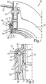
- Fig. 1 shows a schematic perspective view of a section through a brush seal system 10 according to the invention and will be described below in conjunction with Fig. 2 in which an enlarged schematic view of the in Fig. 1 shown details II is shown.
- the brush seal system 10 which is present in the form of a ring segment and can be fastened in a manner known per se to a vane cluster of an aircraft engine, has a brush seal housing 12, which receives a brush head 14 of a brush seal 16 and engages around in a substantially U-shaped manner.
- the brush seal housing 12 is in this case formed in two parts and includes a viewed in the flow direction front cover plate 18 and viewed in the flow direction rear sealing plate 20, which together form a receiving space for receiving the brush head 14 in the mounted state.
- the brush seal housing 12 is formed in one piece or consists of more than two individual components. How to particular in Fig. 2 detects, the cover plate 18 is bent radially below the brush head 14 inwardly, so that the brush head 14 and thus the brush seal 16 captive in the brush seal housing 12 is held and secured. Alternatively or additionally, the brush seal 16 can also be clamped between the cover plate 18 and the sealing plate 20 in order to achieve a positional securing in the brush seal housing 12. In principle, instead of the cover plate 18 or in addition to the cover plate 18, the sealing plate 20 may also be bent in such a way that the brush head 14 accommodated in the brush seal housing 12 is secured in position or fixed in the brush seal housing 12.
- the brush head 14 in turn consists of a clamping tube 22, by means of which fiber or wire bundle 24 are fixed to a core wire 26.
- the fiber or wire bundles 24 protrude from the brush seal housing 12 and form a brush package 28 whose end portion 29 can be brought into abutment with an associated sealing surface of a rotor (not shown) to seal an annular gap between the stator and rotor.
- the brush seal system 10 comprises a separately formed support member 30 with which the brush head 14 opposite end portion 29 of the brush pack 28 can be supported.
- the support member 30, which for this purpose has an upstream end portion 31 viewed in the flow direction, against which the brush package 28 is disposed outside of the brush seal housing 12 and clamped between the sealing plate 20 of the brush seal housing 12 and a stiffening element 32 and thereby secured in position.
- the support element 30, which in the present case is likewise designed in the manner of a ring segment in analogy to the brush seal system 10, can also be connected in a materially bonded manner to the brush seal housing 12 and / or the stiffening element 32.
- the stiffening element 32 is formed as an approximately J-shaped bent metal sheet and connected via rivets 34 with the brush seal housing 12, that is, with the cover plate 18 and the sealing plate 20.
- a sliding element designed as a sliding block 36 is additionally arranged and likewise fixed by means of the rivet 34 on the brush seal system 10.
- the sliding element 36 represents a bearing point with a translational degree of freedom for the memory centering of the brush seal system 10.
- the sliding element 36 engages in a corresponding groove on the guide blade ring during assembly. Due to the memory centering of the brush seal system 10 are due to thermal influences conditional relative dimensional changes between stator and rotor better compensated. In principle, however, the brush seal system 10 of the invention is not limited to this type of mounting.
- the end portion 31 of the support member 30 is closer to the brush head 14 opposite end portion 29 of the brush package 28 arranged as a corresponding end portion 13 of the brush seal housing 12, that is, as the ends 13 of the cover plate 18 and the sealing plate 20. This ensures that in the case of an abutment on the rotor only the support member 30, but not the brush seal housing 12 itself is concerned. Due to the separate design of the support member 30, a repair or replacement of the support member 30 are greatly facilitated after damage.
- the brush seal housing 12 and the support member 30 are designed as separate components, an advantageous separation of the functionalities "housing or securing the brush seal 16" and "support of the brush package 28" is also given.
- the materials for the brush seal housing 12, that is, for the cover plate 18 and the sealing plate 20, as well as for the separate support member 30 can be selected independently.
- the support member 30 may be made of a softer material than the brush seal housing 12 to ensure more adherent performance of the brush seal system 10.
- the support element 30 does not have to be formed as a sheet metal or metal part, but may for example consist of a ceramic material or a ceramic fiber composite material or the like. Further advantages of the separation consist in increasing the structural and geometric freedom of design, so that, for example, different wall thicknesses, different structural mechanical behavior during operation, different sealing effects and the like can be realized in a structurally simple and cost-effective manner.
Landscapes
- Engineering & Computer Science (AREA)
- General Engineering & Computer Science (AREA)
- Mechanical Engineering (AREA)
- Sealing Devices (AREA)
- Turbine Rotor Nozzle Sealing (AREA)
Claims (12)
- Système de joint balai (10) destiné à étanchéifier une fente entre des composants mobiles les uns par rapport aux autres d'une turbine à gaz thermique, ledit système comprenant :- un boîtier de joint balai (12) qui reçoit au moins une tête de balai (14) d'un joint balai (16) afin d'abriter ou de bloquer la position du joint balai (16), et- un élément de support (30) au moyen duquel un paquet de balai (28) faisant saillie de la tête de balai (14) du joint balai (16) peut être supporté sans pouvoir fléchir,dans lequel l'élément de support (30) et le boîtier de joint balai (12) sont conçus sous la forme de composants séparés,
caractérisé en ce que le système de joint balai (10) comprend un élément de raidissement (32) qui est fixé au boîtier de joint balai (12),
dans lequel l'élément de support (30) est disposé entre le boîtier de joint balai (12) et l'élément de raidissement (32). - Système de joint balai (10) selon la revendication 1, caractérisé en ce qu'une zone d'extrémité (31) de l'élément de support (30) est disposée plus près d'une extrémité (29), opposée à la tête de balai (14) du paquet de balai (28) qu'une zone d'extrémité (13) du boîtier de joint balai (12).
- Système de joint balai (10) selon la revendication 1 ou 2, caractérisé en ce que l'élément de support (30) est fixé au boîtier de joint balai (12) par complémentarité de formes et/ou par liaison de matière.
- Système de joint balai (10) selon l'une quelconque des revendications 1 à 3, caractérisé en ce que l'élément de support (30) est disposé à l'intérieur et/ou à l'extérieur du boîtier de joint balai (12).
- Système de joint balai (10) selon l'une quelconque des revendications 1 à 4, caractérisé en ce que l'élément de support (30) a une forme d'anneau et/ou de segment d'anneau.
- Système de joint balai (10) selon l'une quelconque des revendications 1 à 5, caractérisé en ce que l'élément de support (30) est constitué d'un matériau différent de celui du boîtier de joint balai (12) et/ou possède une épaisseur de paroi différente de celle du boîtier de joint balai (12).
- Système de joint balai (10) selon l'une quelconque des revendications 1 à 6, caractérisé en ce que le boîtier de joint balai (12) est constitué de plusieurs parties, notamment de deux parties.
- Système de joint balai (10) selon l'une quelconque des revendications 1 à 7, caractérisé en ce que l'élément de raidissement (32) est réalisé sous la forme d'une plaque métallique pliée et/ou en ce que l'élément de raidissement (32) est rivé au boîtier de joint balai (12) et/ou en ce qu'au moins un élément coulissant (36), en particulier un bloc coulissant, est disposé entre l'élément de raidissement (32) et le boîtier de joint balai (12).
- Procédé de fabrication d'un système de joint balai (10) destiné à étanchéifier une fente entre des composants mobiles les uns par rapport aux autres d'une turbine à gaz thermique, le procédé comprenant les étapes visant à :- produire un boîtier de joint balai (12) ;- placer un joint balai (16) dans le boîtier de joint balai (12) de sorte qu'au moins une tête de balai (14) du joint balai (16) soit reçue dans le boîtier de joint balai (12) ;- produire un élément de support séparé (30) ; et- placer l'élément de support (30) sur le boîtier de joint balai (12) de sorte qu'un paquet de balai (28), saillant de la tête de balai (14) du joint balai (16), peut être supporté par l'élément de support (30) sans pouvoir fléchir.
- Turbine à gaz thermique, en particulier moteur d'aéronef, comprenant au moins un système de joint balai (10) qui est conçu selon l'une quelconque des revendications 1 à 8 et/ou qui peut être obtenu par un procédé selon la revendication 9.
- Turbine à gaz thermique selon la revendication 10, caractérisée en ce que, pour étanchéifier une fente entre un rotor et un stator de la turbine à gaz, le boîtier de joint balai (12) du système de joint balai (10) est fixé au stator.
- Turbine à gaz thermique selon la revendication 11, caractérisée en ce que le stator est conçu comme une aube directrice et/ou comme un groupe d'aubes directrices et/ou comme une couronne d'aubes directrices.
Applications Claiming Priority (1)
| Application Number | Priority Date | Filing Date | Title |
|---|---|---|---|
| DE102013220168.0A DE102013220168B4 (de) | 2013-10-07 | 2013-10-07 | Bürstendichtungssystem zum Abdichten eines Spalts zwischen relativ zueinander bewegbaren Bauteilen einer thermischen Gasturbine |
Publications (2)
| Publication Number | Publication Date |
|---|---|
| EP2857721A1 EP2857721A1 (fr) | 2015-04-08 |
| EP2857721B1 true EP2857721B1 (fr) | 2018-01-17 |
Family
ID=51625896
Family Applications (1)
| Application Number | Title | Priority Date | Filing Date |
|---|---|---|---|
| EP14186636.8A Active EP2857721B1 (fr) | 2013-10-07 | 2014-09-26 | Système de joint balai destiné à étanchéifier une fente entre des composants mobiles les uns par rapport aux autres d'une turbine à gaz thermique |
Country Status (3)
| Country | Link |
|---|---|
| US (1) | US9777588B2 (fr) |
| EP (1) | EP2857721B1 (fr) |
| DE (1) | DE102013220168B4 (fr) |
Families Citing this family (4)
| Publication number | Priority date | Publication date | Assignee | Title |
|---|---|---|---|---|
| DE102014212174A1 (de) | 2014-06-25 | 2015-12-31 | MTU Aero Engines AG | Bürstendichtungssystem zum Abdichten eines Spalts zwischen relativ zueinander bewegbaren Bauteilen einer Strömungsmaschine |
| US20190249605A1 (en) * | 2018-02-12 | 2019-08-15 | United Technologies Corporation | Aircraft engine seal carrier including anti-rotation feature |
| DE102023101856A1 (de) | 2023-01-25 | 2024-07-25 | MTU Aero Engines AG | Bürstendichtung für eine Turbomaschine |
| WO2025176266A1 (fr) | 2024-02-23 | 2025-08-28 | MTU Aero Engines AG | Joint brosse et procédé de fabrication du joint brosse |
Citations (1)
| Publication number | Priority date | Publication date | Assignee | Title |
|---|---|---|---|---|
| DE102013213386B3 (de) * | 2013-07-09 | 2014-08-14 | MTU Aero Engines AG | Strömungsmaschinen-Keramikbauteil |
Family Cites Families (20)
| Publication number | Priority date | Publication date | Assignee | Title |
|---|---|---|---|---|
| US5351971A (en) * | 1993-05-21 | 1994-10-04 | Eg&G Sealol, Inc. | Brush seal device having a floating backplate |
| DE19529655C2 (de) | 1995-08-11 | 1999-04-22 | Mtu Muenchen Gmbh | Bürstendichtung für Turbomaschinen |
| US6173962B1 (en) * | 1995-12-09 | 2001-01-16 | Rolls Royce Plc | Brush seal |
| DE19720649C2 (de) * | 1997-05-16 | 2000-09-28 | Mtu Muenchen Gmbh | Bürstendichtung |
| DE19720648C2 (de) * | 1997-05-16 | 2000-07-13 | Mtu Muenchen Gmbh | Bürstendichtung mit Front- und Stützplatte |
| GB9900102D0 (en) * | 1999-01-06 | 1999-02-24 | Rolls Royce Plc | A seal arrangement |
| GB9929587D0 (en) * | 1999-12-16 | 2000-02-09 | Rolls Royce Plc | A seal arrangement |
| DE19962316C2 (de) * | 1999-12-23 | 2002-07-18 | Mtu Aero Engines Gmbh | Bürstendichtung |
| DE10018273B4 (de) | 2000-04-13 | 2005-10-20 | Mtu Aero Engines Gmbh | Bürstendichtung |
| GB0201666D0 (en) * | 2002-01-25 | 2002-03-13 | Cross Mfg 1938 Company Ltd | A brush seal element |
| US7931276B2 (en) * | 2002-03-20 | 2011-04-26 | United Technologies Corporation | Brush seal |
| US6685427B1 (en) * | 2002-07-23 | 2004-02-03 | General Electric Company | Brush seal for a rotary machine and method of retrofitting |
| DE10337867B4 (de) * | 2003-08-18 | 2020-04-23 | MTU Aero Engines AG | Bürstendichtung |
| EP1522773A1 (fr) * | 2003-10-08 | 2005-04-13 | United Technologies Corporation | Joint à brosses |
| US20080284107A1 (en) * | 2004-05-04 | 2008-11-20 | Flaherty Andrew L | Ceramic Brush Seals |
| DE102005006939A1 (de) * | 2005-02-16 | 2006-08-24 | Mtu Aero Engines Gmbh | Dichtungsanordnung |
| DE102005017037A1 (de) * | 2005-04-13 | 2006-10-19 | Mtu Aero Engines Gmbh | Dichtungsanordnung |
| EP1892442A1 (fr) * | 2006-08-18 | 2008-02-27 | Siemens Aktiengesellschaft | Joint à brosse pour turbomachine |
| EP2137437A2 (fr) * | 2007-03-15 | 2009-12-30 | Rexnord Industries, LLC | Ensemble de joint d'étanchéité à balai et son procédé de fabrication |
| EP2147237A1 (fr) * | 2007-04-16 | 2010-01-27 | Rexnord Industries, LLC | Joint-balai |
-
2013
- 2013-10-07 DE DE102013220168.0A patent/DE102013220168B4/de active Active
-
2014
- 2014-09-26 EP EP14186636.8A patent/EP2857721B1/fr active Active
- 2014-10-07 US US14/508,212 patent/US9777588B2/en not_active Expired - Fee Related
Patent Citations (1)
| Publication number | Priority date | Publication date | Assignee | Title |
|---|---|---|---|---|
| DE102013213386B3 (de) * | 2013-07-09 | 2014-08-14 | MTU Aero Engines AG | Strömungsmaschinen-Keramikbauteil |
Also Published As
| Publication number | Publication date |
|---|---|
| US20150098798A1 (en) | 2015-04-09 |
| EP2857721A1 (fr) | 2015-04-08 |
| US9777588B2 (en) | 2017-10-03 |
| DE102013220168B4 (de) | 2015-08-27 |
| DE102013220168A1 (de) | 2015-05-13 |
Similar Documents
| Publication | Publication Date | Title |
|---|---|---|
| EP2960555B1 (fr) | Système de joint à brosse pour sceller un intervalle entre les éléments d'une turbomachine qui peuvent être déplacés les uns par rapport aux autres | |
| DE60200663T2 (de) | Bürstendichtung | |
| DE102010054113B4 (de) | Dichtung und Strömungsmaschine | |
| EP2857721B1 (fr) | Système de joint balai destiné à étanchéifier une fente entre des composants mobiles les uns par rapport aux autres d'une turbine à gaz thermique | |
| EP3208428B1 (fr) | Agencement d'étanchéification en matériaux composites à fibres ceramiques | |
| WO2010086005A2 (fr) | Turbocompresseur à gaz d'échappement pour un moteur à combustion interne | |
| DE10017643A1 (de) | Dichtung in nicht-hermetischer Ausführung | |
| EP3204187B1 (fr) | Procédé de montage d'aubes rotoriques sur un disque de rotor et tensionneur associé destiné à mettre en oeuvre un tel procédé | |
| EP3231998B1 (fr) | Segment d'une aube statorique | |
| EP3241995B1 (fr) | Segment d'aube directrice pour une turbo-machine | |
| EP3574188B1 (fr) | Procédé permettant de fermer de manière étanche un interstice annulaire dans une turbine ainsi que turbine | |
| EP2811118B1 (fr) | Segment d'aube directrice d'une turbomachine et turbine | |
| DE102015212502A1 (de) | Verfahren zum Reinigen einer Radscheibenanordnung und/oder an dieser gehaltener Schaufeln | |
| EP3287608B1 (fr) | Bague intérieure d'une couronne d'aubes directrices d'une turbomachine | |
| EP2994615B1 (fr) | Rotor pour une turbomachine thermique | |
| EP2526263B1 (fr) | Système de boîtier pour une turbomachine axiale | |
| EP2577117B1 (fr) | Procédé pour fixer un élément d'étanchéité à brosse dans une rainure d'un segment de boîtier | |
| EP3628030B1 (fr) | Méthode de maintenance d'une turbomachine | |
| EP1707759B1 (fr) | Carter d'une turbomachine | |
| EP2884051A1 (fr) | Rotor de turbomachine, turbomachine, compresseur axial, turbine à gaz et procédé de fabrication d'un rotor de turbomachine | |
| EP2333249A2 (fr) | Carter central d'un turbocompresseur | |
| EP2787175B1 (fr) | Système de sécurité et procédé de sécurité d'une zone de fixation d'au moins une aube de rotor ou d'un segment d'aube de rotor dans une zone de montage d'un palier de rotor | |
| EP1890056A1 (fr) | Joint à brosses pour une turbomachine | |
| WO2021008815A1 (fr) | Couronne d'aube servant à une turbomachine axiale | |
| EP2980460B1 (fr) | Construction et fabrication générative d'un joint intégral |
Legal Events
| Date | Code | Title | Description |
|---|---|---|---|
| PUAI | Public reference made under article 153(3) epc to a published international application that has entered the european phase |
Free format text: ORIGINAL CODE: 0009012 |
|
| 17P | Request for examination filed |
Effective date: 20140926 |
|
| AK | Designated contracting states |
Kind code of ref document: A1 Designated state(s): AL AT BE BG CH CY CZ DE DK EE ES FI FR GB GR HR HU IE IS IT LI LT LU LV MC MK MT NL NO PL PT RO RS SE SI SK SM TR |
|
| AX | Request for extension of the european patent |
Extension state: BA ME |
|
| R17P | Request for examination filed (corrected) |
Effective date: 20151008 |
|
| RBV | Designated contracting states (corrected) |
Designated state(s): AL AT BE BG CH CY CZ DE DK EE ES FI FR GB GR HR HU IE IS IT LI LT LU LV MC MK MT NL NO PL PT RO RS SE SI SK SM TR |
|
| 17Q | First examination report despatched |
Effective date: 20160624 |
|
| REG | Reference to a national code |
Ref country code: DE Ref legal event code: R079 Ref document number: 502014006984 Country of ref document: DE Free format text: PREVIOUS MAIN CLASS: F16J0015320000 Ipc: F01D0011000000 |
|
| GRAP | Despatch of communication of intention to grant a patent |
Free format text: ORIGINAL CODE: EPIDOSNIGR1 |
|
| RIC1 | Information provided on ipc code assigned before grant |
Ipc: F16J 15/3288 20160101ALI20171010BHEP Ipc: F01D 11/00 20060101AFI20171010BHEP |
|
| GRAS | Grant fee paid |
Free format text: ORIGINAL CODE: EPIDOSNIGR3 |
|
| INTG | Intention to grant announced |
Effective date: 20171113 |
|
| GRAA | (expected) grant |
Free format text: ORIGINAL CODE: 0009210 |
|
| AK | Designated contracting states |
Kind code of ref document: B1 Designated state(s): AL AT BE BG CH CY CZ DE DK EE ES FI FR GB GR HR HU IE IS IT LI LT LU LV MC MK MT NL NO PL PT RO RS SE SI SK SM TR |
|
| REG | Reference to a national code |
Ref country code: GB Ref legal event code: FG4D Free format text: NOT ENGLISH |
|
| REG | Reference to a national code |
Ref country code: CH Ref legal event code: EP |
|
| REG | Reference to a national code |
Ref country code: IE Ref legal event code: FG4D Free format text: LANGUAGE OF EP DOCUMENT: GERMAN |
|
| REG | Reference to a national code |
Ref country code: AT Ref legal event code: REF Ref document number: 964576 Country of ref document: AT Kind code of ref document: T Effective date: 20180215 |
|
| REG | Reference to a national code |
Ref country code: DE Ref legal event code: R096 Ref document number: 502014006984 Country of ref document: DE |
|
| REG | Reference to a national code |
Ref country code: NL Ref legal event code: MP Effective date: 20180117 |
|
| REG | Reference to a national code |
Ref country code: LT Ref legal event code: MG4D |
|
| PG25 | Lapsed in a contracting state [announced via postgrant information from national office to epo] |
Ref country code: NL Free format text: LAPSE BECAUSE OF FAILURE TO SUBMIT A TRANSLATION OF THE DESCRIPTION OR TO PAY THE FEE WITHIN THE PRESCRIBED TIME-LIMIT Effective date: 20180117 |
|
| PG25 | Lapsed in a contracting state [announced via postgrant information from national office to epo] |
Ref country code: NO Free format text: LAPSE BECAUSE OF FAILURE TO SUBMIT A TRANSLATION OF THE DESCRIPTION OR TO PAY THE FEE WITHIN THE PRESCRIBED TIME-LIMIT Effective date: 20180417 Ref country code: CY Free format text: LAPSE BECAUSE OF FAILURE TO SUBMIT A TRANSLATION OF THE DESCRIPTION OR TO PAY THE FEE WITHIN THE PRESCRIBED TIME-LIMIT Effective date: 20180117 Ref country code: HR Free format text: LAPSE BECAUSE OF FAILURE TO SUBMIT A TRANSLATION OF THE DESCRIPTION OR TO PAY THE FEE WITHIN THE PRESCRIBED TIME-LIMIT Effective date: 20180117 Ref country code: FI Free format text: LAPSE BECAUSE OF FAILURE TO SUBMIT A TRANSLATION OF THE DESCRIPTION OR TO PAY THE FEE WITHIN THE PRESCRIBED TIME-LIMIT Effective date: 20180117 Ref country code: ES Free format text: LAPSE BECAUSE OF FAILURE TO SUBMIT A TRANSLATION OF THE DESCRIPTION OR TO PAY THE FEE WITHIN THE PRESCRIBED TIME-LIMIT Effective date: 20180117 Ref country code: LT Free format text: LAPSE BECAUSE OF FAILURE TO SUBMIT A TRANSLATION OF THE DESCRIPTION OR TO PAY THE FEE WITHIN THE PRESCRIBED TIME-LIMIT Effective date: 20180117 |
|
| PG25 | Lapsed in a contracting state [announced via postgrant information from national office to epo] |
Ref country code: PL Free format text: LAPSE BECAUSE OF FAILURE TO SUBMIT A TRANSLATION OF THE DESCRIPTION OR TO PAY THE FEE WITHIN THE PRESCRIBED TIME-LIMIT Effective date: 20180117 Ref country code: GR Free format text: LAPSE BECAUSE OF FAILURE TO SUBMIT A TRANSLATION OF THE DESCRIPTION OR TO PAY THE FEE WITHIN THE PRESCRIBED TIME-LIMIT Effective date: 20180418 Ref country code: BG Free format text: LAPSE BECAUSE OF FAILURE TO SUBMIT A TRANSLATION OF THE DESCRIPTION OR TO PAY THE FEE WITHIN THE PRESCRIBED TIME-LIMIT Effective date: 20180417 Ref country code: IS Free format text: LAPSE BECAUSE OF FAILURE TO SUBMIT A TRANSLATION OF THE DESCRIPTION OR TO PAY THE FEE WITHIN THE PRESCRIBED TIME-LIMIT Effective date: 20180517 Ref country code: SE Free format text: LAPSE BECAUSE OF FAILURE TO SUBMIT A TRANSLATION OF THE DESCRIPTION OR TO PAY THE FEE WITHIN THE PRESCRIBED TIME-LIMIT Effective date: 20180117 Ref country code: LV Free format text: LAPSE BECAUSE OF FAILURE TO SUBMIT A TRANSLATION OF THE DESCRIPTION OR TO PAY THE FEE WITHIN THE PRESCRIBED TIME-LIMIT Effective date: 20180117 Ref country code: RS Free format text: LAPSE BECAUSE OF FAILURE TO SUBMIT A TRANSLATION OF THE DESCRIPTION OR TO PAY THE FEE WITHIN THE PRESCRIBED TIME-LIMIT Effective date: 20180117 |
|
| REG | Reference to a national code |
Ref country code: FR Ref legal event code: PLFP Year of fee payment: 5 |
|
| PG25 | Lapsed in a contracting state [announced via postgrant information from national office to epo] |
Ref country code: MT Free format text: LAPSE BECAUSE OF FAILURE TO SUBMIT A TRANSLATION OF THE DESCRIPTION OR TO PAY THE FEE WITHIN THE PRESCRIBED TIME-LIMIT Effective date: 20180117 |
|
| REG | Reference to a national code |
Ref country code: DE Ref legal event code: R097 Ref document number: 502014006984 Country of ref document: DE |
|
| PG25 | Lapsed in a contracting state [announced via postgrant information from national office to epo] |
Ref country code: EE Free format text: LAPSE BECAUSE OF FAILURE TO SUBMIT A TRANSLATION OF THE DESCRIPTION OR TO PAY THE FEE WITHIN THE PRESCRIBED TIME-LIMIT Effective date: 20180117 Ref country code: RO Free format text: LAPSE BECAUSE OF FAILURE TO SUBMIT A TRANSLATION OF THE DESCRIPTION OR TO PAY THE FEE WITHIN THE PRESCRIBED TIME-LIMIT Effective date: 20180117 Ref country code: IT Free format text: LAPSE BECAUSE OF FAILURE TO SUBMIT A TRANSLATION OF THE DESCRIPTION OR TO PAY THE FEE WITHIN THE PRESCRIBED TIME-LIMIT Effective date: 20180117 Ref country code: AL Free format text: LAPSE BECAUSE OF FAILURE TO SUBMIT A TRANSLATION OF THE DESCRIPTION OR TO PAY THE FEE WITHIN THE PRESCRIBED TIME-LIMIT Effective date: 20180117 |
|
| PLBE | No opposition filed within time limit |
Free format text: ORIGINAL CODE: 0009261 |
|
| STAA | Information on the status of an ep patent application or granted ep patent |
Free format text: STATUS: NO OPPOSITION FILED WITHIN TIME LIMIT |
|
| PG25 | Lapsed in a contracting state [announced via postgrant information from national office to epo] |
Ref country code: CZ Free format text: LAPSE BECAUSE OF FAILURE TO SUBMIT A TRANSLATION OF THE DESCRIPTION OR TO PAY THE FEE WITHIN THE PRESCRIBED TIME-LIMIT Effective date: 20180117 Ref country code: SK Free format text: LAPSE BECAUSE OF FAILURE TO SUBMIT A TRANSLATION OF THE DESCRIPTION OR TO PAY THE FEE WITHIN THE PRESCRIBED TIME-LIMIT Effective date: 20180117 Ref country code: DK Free format text: LAPSE BECAUSE OF FAILURE TO SUBMIT A TRANSLATION OF THE DESCRIPTION OR TO PAY THE FEE WITHIN THE PRESCRIBED TIME-LIMIT Effective date: 20180117 Ref country code: SM Free format text: LAPSE BECAUSE OF FAILURE TO SUBMIT A TRANSLATION OF THE DESCRIPTION OR TO PAY THE FEE WITHIN THE PRESCRIBED TIME-LIMIT Effective date: 20180117 |
|
| 26N | No opposition filed |
Effective date: 20181018 |
|
| PG25 | Lapsed in a contracting state [announced via postgrant information from national office to epo] |
Ref country code: SI Free format text: LAPSE BECAUSE OF FAILURE TO SUBMIT A TRANSLATION OF THE DESCRIPTION OR TO PAY THE FEE WITHIN THE PRESCRIBED TIME-LIMIT Effective date: 20180117 |
|
| PG25 | Lapsed in a contracting state [announced via postgrant information from national office to epo] |
Ref country code: MC Free format text: LAPSE BECAUSE OF FAILURE TO SUBMIT A TRANSLATION OF THE DESCRIPTION OR TO PAY THE FEE WITHIN THE PRESCRIBED TIME-LIMIT Effective date: 20180117 |
|
| REG | Reference to a national code |
Ref country code: CH Ref legal event code: PL |
|
| REG | Reference to a national code |
Ref country code: BE Ref legal event code: MM Effective date: 20180930 |
|
| REG | Reference to a national code |
Ref country code: IE Ref legal event code: MM4A |
|
| PG25 | Lapsed in a contracting state [announced via postgrant information from national office to epo] |
Ref country code: LU Free format text: LAPSE BECAUSE OF NON-PAYMENT OF DUE FEES Effective date: 20180926 |
|
| PG25 | Lapsed in a contracting state [announced via postgrant information from national office to epo] |
Ref country code: IE Free format text: LAPSE BECAUSE OF NON-PAYMENT OF DUE FEES Effective date: 20180926 |
|
| PG25 | Lapsed in a contracting state [announced via postgrant information from national office to epo] |
Ref country code: BE Free format text: LAPSE BECAUSE OF NON-PAYMENT OF DUE FEES Effective date: 20180930 Ref country code: LI Free format text: LAPSE BECAUSE OF NON-PAYMENT OF DUE FEES Effective date: 20180930 Ref country code: CH Free format text: LAPSE BECAUSE OF NON-PAYMENT OF DUE FEES Effective date: 20180930 |
|
| PG25 | Lapsed in a contracting state [announced via postgrant information from national office to epo] |
Ref country code: TR Free format text: LAPSE BECAUSE OF FAILURE TO SUBMIT A TRANSLATION OF THE DESCRIPTION OR TO PAY THE FEE WITHIN THE PRESCRIBED TIME-LIMIT Effective date: 20180117 |
|
| PG25 | Lapsed in a contracting state [announced via postgrant information from national office to epo] |
Ref country code: PT Free format text: LAPSE BECAUSE OF FAILURE TO SUBMIT A TRANSLATION OF THE DESCRIPTION OR TO PAY THE FEE WITHIN THE PRESCRIBED TIME-LIMIT Effective date: 20180117 Ref country code: HU Free format text: LAPSE BECAUSE OF FAILURE TO SUBMIT A TRANSLATION OF THE DESCRIPTION OR TO PAY THE FEE WITHIN THE PRESCRIBED TIME-LIMIT; INVALID AB INITIO Effective date: 20140926 |
|
| PG25 | Lapsed in a contracting state [announced via postgrant information from national office to epo] |
Ref country code: MK Free format text: LAPSE BECAUSE OF NON-PAYMENT OF DUE FEES Effective date: 20180117 |
|
| REG | Reference to a national code |
Ref country code: AT Ref legal event code: MM01 Ref document number: 964576 Country of ref document: AT Kind code of ref document: T Effective date: 20190926 |
|
| PG25 | Lapsed in a contracting state [announced via postgrant information from national office to epo] |
Ref country code: AT Free format text: LAPSE BECAUSE OF NON-PAYMENT OF DUE FEES Effective date: 20190926 |
|
| PGFP | Annual fee paid to national office [announced via postgrant information from national office to epo] |
Ref country code: DE Payment date: 20240919 Year of fee payment: 11 |
|
| PGFP | Annual fee paid to national office [announced via postgrant information from national office to epo] |
Ref country code: GB Payment date: 20240923 Year of fee payment: 11 |
|
| PGFP | Annual fee paid to national office [announced via postgrant information from national office to epo] |
Ref country code: FR Payment date: 20240925 Year of fee payment: 11 |