EP2980460B1 - Construction et fabrication générative d'un joint intégral - Google Patents
Construction et fabrication générative d'un joint intégral Download PDFInfo
- Publication number
- EP2980460B1 EP2980460B1 EP14179331.5A EP14179331A EP2980460B1 EP 2980460 B1 EP2980460 B1 EP 2980460B1 EP 14179331 A EP14179331 A EP 14179331A EP 2980460 B1 EP2980460 B1 EP 2980460B1
- Authority
- EP
- European Patent Office
- Prior art keywords
- leaf
- base element
- seal
- leaf seal
- leaves
- Prior art date
- Legal status (The legal status is an assumption and is not a legal conclusion. Google has not performed a legal analysis and makes no representation as to the accuracy of the status listed.)
- Active
Links
Images


Classifications
-
- F—MECHANICAL ENGINEERING; LIGHTING; HEATING; WEAPONS; BLASTING
- F01—MACHINES OR ENGINES IN GENERAL; ENGINE PLANTS IN GENERAL; STEAM ENGINES
- F01D—NON-POSITIVE DISPLACEMENT MACHINES OR ENGINES, e.g. STEAM TURBINES
- F01D11/00—Preventing or minimising internal leakage of working-fluid, e.g. between stages
- F01D11/001—Preventing or minimising internal leakage of working-fluid, e.g. between stages for sealing space between stator blade and rotor
-
- F—MECHANICAL ENGINEERING; LIGHTING; HEATING; WEAPONS; BLASTING
- F01—MACHINES OR ENGINES IN GENERAL; ENGINE PLANTS IN GENERAL; STEAM ENGINES
- F01D—NON-POSITIVE DISPLACEMENT MACHINES OR ENGINES, e.g. STEAM TURBINES
- F01D11/00—Preventing or minimising internal leakage of working-fluid, e.g. between stages
- F01D11/003—Preventing or minimising internal leakage of working-fluid, e.g. between stages by packing rings; Mechanical seals
-
- F—MECHANICAL ENGINEERING; LIGHTING; HEATING; WEAPONS; BLASTING
- F01—MACHINES OR ENGINES IN GENERAL; ENGINE PLANTS IN GENERAL; STEAM ENGINES
- F01D—NON-POSITIVE DISPLACEMENT MACHINES OR ENGINES, e.g. STEAM TURBINES
- F01D11/00—Preventing or minimising internal leakage of working-fluid, e.g. between stages
- F01D11/005—Sealing means between non relatively rotating elements
-
- F—MECHANICAL ENGINEERING; LIGHTING; HEATING; WEAPONS; BLASTING
- F01—MACHINES OR ENGINES IN GENERAL; ENGINE PLANTS IN GENERAL; STEAM ENGINES
- F01D—NON-POSITIVE DISPLACEMENT MACHINES OR ENGINES, e.g. STEAM TURBINES
- F01D25/00—Component parts, details, or accessories, not provided for in, or of interest apart from, other groups
- F01D25/24—Casings; Casing parts, e.g. diaphragms, casing fastenings
-
- F—MECHANICAL ENGINEERING; LIGHTING; HEATING; WEAPONS; BLASTING
- F01—MACHINES OR ENGINES IN GENERAL; ENGINE PLANTS IN GENERAL; STEAM ENGINES
- F01D—NON-POSITIVE DISPLACEMENT MACHINES OR ENGINES, e.g. STEAM TURBINES
- F01D5/00—Blades; Blade-carrying members; Heating, heat-insulating, cooling or antivibration means on the blades or the members
- F01D5/02—Blade-carrying members, e.g. rotors
-
- F—MECHANICAL ENGINEERING; LIGHTING; HEATING; WEAPONS; BLASTING
- F16—ENGINEERING ELEMENTS AND UNITS; GENERAL MEASURES FOR PRODUCING AND MAINTAINING EFFECTIVE FUNCTIONING OF MACHINES OR INSTALLATIONS; THERMAL INSULATION IN GENERAL
- F16J—PISTONS; CYLINDERS; SEALINGS
- F16J15/00—Sealings
- F16J15/16—Sealings between relatively-moving surfaces
- F16J15/32—Sealings between relatively-moving surfaces with elastic sealings, e.g. O-rings
- F16J15/3284—Sealings between relatively-moving surfaces with elastic sealings, e.g. O-rings characterised by their structure; Selection of materials
- F16J15/3292—Lamellar structures
-
- B—PERFORMING OPERATIONS; TRANSPORTING
- B22—CASTING; POWDER METALLURGY
- B22F—WORKING METALLIC POWDER; MANUFACTURE OF ARTICLES FROM METALLIC POWDER; MAKING METALLIC POWDER; APPARATUS OR DEVICES SPECIALLY ADAPTED FOR METALLIC POWDER
- B22F10/00—Additive manufacturing of workpieces or articles from metallic powder
- B22F10/20—Direct sintering or melting
- B22F10/28—Powder bed fusion, e.g. selective laser melting [SLM] or electron beam melting [EBM]
-
- B—PERFORMING OPERATIONS; TRANSPORTING
- B22—CASTING; POWDER METALLURGY
- B22F—WORKING METALLIC POWDER; MANUFACTURE OF ARTICLES FROM METALLIC POWDER; MAKING METALLIC POWDER; APPARATUS OR DEVICES SPECIALLY ADAPTED FOR METALLIC POWDER
- B22F10/00—Additive manufacturing of workpieces or articles from metallic powder
- B22F10/40—Structures for supporting workpieces or articles during manufacture and removed afterwards
- B22F10/47—Structures for supporting workpieces or articles during manufacture and removed afterwards characterised by structural features
-
- B—PERFORMING OPERATIONS; TRANSPORTING
- B33—ADDITIVE MANUFACTURING TECHNOLOGY
- B33Y—ADDITIVE MANUFACTURING, i.e. MANUFACTURING OF THREE-DIMENSIONAL [3D] OBJECTS BY ADDITIVE DEPOSITION, ADDITIVE AGGLOMERATION OR ADDITIVE LAYERING, e.g. BY 3D PRINTING, STEREOLITHOGRAPHY OR SELECTIVE LASER SINTERING
- B33Y10/00—Processes of additive manufacturing
-
- F—MECHANICAL ENGINEERING; LIGHTING; HEATING; WEAPONS; BLASTING
- F05—INDEXING SCHEMES RELATING TO ENGINES OR PUMPS IN VARIOUS SUBCLASSES OF CLASSES F01-F04
- F05D—INDEXING SCHEME FOR ASPECTS RELATING TO NON-POSITIVE-DISPLACEMENT MACHINES OR ENGINES, GAS-TURBINES OR JET-PROPULSION PLANTS
- F05D2220/00—Application
- F05D2220/30—Application in turbines
- F05D2220/32—Application in turbines in gas turbines
-
- F—MECHANICAL ENGINEERING; LIGHTING; HEATING; WEAPONS; BLASTING
- F05—INDEXING SCHEMES RELATING TO ENGINES OR PUMPS IN VARIOUS SUBCLASSES OF CLASSES F01-F04
- F05D—INDEXING SCHEME FOR ASPECTS RELATING TO NON-POSITIVE-DISPLACEMENT MACHINES OR ENGINES, GAS-TURBINES OR JET-PROPULSION PLANTS
- F05D2240/00—Components
- F05D2240/55—Seals
- F05D2240/57—Leaf seals
-
- F—MECHANICAL ENGINEERING; LIGHTING; HEATING; WEAPONS; BLASTING
- F05—INDEXING SCHEMES RELATING TO ENGINES OR PUMPS IN VARIOUS SUBCLASSES OF CLASSES F01-F04
- F05D—INDEXING SCHEME FOR ASPECTS RELATING TO NON-POSITIVE-DISPLACEMENT MACHINES OR ENGINES, GAS-TURBINES OR JET-PROPULSION PLANTS
- F05D2240/00—Components
- F05D2240/55—Seals
- F05D2240/59—Lamellar seals
-
- Y—GENERAL TAGGING OF NEW TECHNOLOGICAL DEVELOPMENTS; GENERAL TAGGING OF CROSS-SECTIONAL TECHNOLOGIES SPANNING OVER SEVERAL SECTIONS OF THE IPC; TECHNICAL SUBJECTS COVERED BY FORMER USPC CROSS-REFERENCE ART COLLECTIONS [XRACs] AND DIGESTS
- Y02—TECHNOLOGIES OR APPLICATIONS FOR MITIGATION OR ADAPTATION AGAINST CLIMATE CHANGE
- Y02P—CLIMATE CHANGE MITIGATION TECHNOLOGIES IN THE PRODUCTION OR PROCESSING OF GOODS
- Y02P10/00—Technologies related to metal processing
- Y02P10/25—Process efficiency
Definitions
- the invention relates to a lamellar seal for sealing a shaft rotating about an axis, in particular in a gas turbine.
- the invention further relates to a gas turbine with such a lamellar seal and a method for producing such a lamellar seal.
- brush seals are often used in engine construction to seal gaps between a rotor and a stator. Due to their mechanical integrity, brush seals are one of the contact seals that wear both during operation and the friction partner when touched. In addition, brush seals can only be used up to a differential pressure of approximately 12 bar.
- lamellar seals which, due to their axial rigidity, can also be used in environments with very high pressure differences and, moreover, wear out more slowly than brush seals.
- a lamellar seal which is also referred to as "Leafseal”
- Leafseal is already known from, for example DE 10 2004 020 378 A1
- a similar seal is also out US 2003/0174918 known.
- lamellar seals for example in the engine area, can include up to 4000 lamellas or more. Because of Due to the comparatively filigree design of the individual lamellae, the known lamella seals cannot be prefabricated in a practical size for engine applications and cannot be adapted to different installation situations or only with great effort. In addition, a correspondingly high effort has to be made to ensure sufficient reproducibility of such individually manufactured lamella seals.
- a first aspect of the invention relates to a lamellar seal for sealing a shaft rotating about an axis, in particular in a gas turbine, comprising a plurality of lamellas arranged at a distance from one another, it being provided according to the invention that the lamellas are integral with a base element carrying the lamellas by means of a generative manufacturing process are manufactured.
- the lamella seal is produced generatively, the individual lamellae being connected to one another via a base element.
- the lamella seal according to the invention is quicker and easier to produce.
- additive manufacturing enables a high degree of design freedom and flexibility, so that the lamella seal according to the invention can also be more easily adapted to different installation situations.
- the integral design enables, for example, a simple modification of the distances between the individual lamellas or sealing elements, so that the lamellar seal can be quickly and easily adapted to any shaft diameter or gap geometry.
- the rigidity of each individual slat can be infinitely variable to meet the requirements be adjusted.
- additive manufacturing enables a very wide range of sheet thicknesses, so that the individual lamellae can have average thicknesses of between 0.1 mm and 4 mm, for example, independently of one another.
- the shape or geometry of the individual slats can also be optimally adapted to the respective requirements.
- the material used in the additive manufacturing process one or more times in order to set specific properties of the lamella seal.
- the base element can also be designed independently of the slats.
- the base element can be designed as a cover band, which is manufactured together with the leaves (Leafs) as an integral association and can be installed as a plate seal in any housing configuration.
- At least one lamella has an uneven cross-sectional geometry.
- one, several or all of the lamellae have a non-uniform cross-sectional geometry.
- one or more local thickenings and / or thinners can be provided on each lamella. In this way, for example, the elastic beige behavior of each slat can be optimally adjusted.
- At least one lamella has a reduced cross-sectional thickness in the region of the base element.
- Such a recess facilitates a relative tilting of the lamella in question relative to the base element, so that an improved System on an associated shaft and thus an improved sealing effect can be achieved.
- several or all of the slats can be designed in this way.
- At least one lamella comprises a spacer element for setting a minimum distance from an adjacent lamella.
- the spacer element can be designed, for example, as a thickened region of the lamella and can preferably be formed on the end region of the lamella opposite the base element.
- At least one lamella is arranged at a predetermined laying angle and / or at a predetermined angle of attack with respect to a longitudinal axis of the base element.
- the angle of inclination of the lamella and / or the angle between the longitudinal axis of the base element and the chord of the lamella in question can in principle be chosen freely.
- the angle of inclination and / or the angle between the longitudinal axis of the base element and the chord of the slat in question can thus independently of one another, for example, values of 5 °, 10 °, 15 °, 20 °, 25 °, 30 °, 35 °, 40 °, 45 °, 50 °, 55 °, 60 °, 65 °, 70 °, 75 °, 80 °, 85 ° or 90 ° as well as corresponding intermediate values.
- the base element comprises at least one fastening means for fixing the lamella seal to a component, in particular to a housing part.
- the at least one fastening means is arranged on a side of the base element facing away from the slats. This enables a particularly simple fastening of the lamella seal in an associated holder.
- the at least one fastening means is produced integrally with the base element by means of the additive manufacturing method.
- the integral production of the at least one fastening means with the base element represents a structurally particularly simple and quick way of equipping the base element with the at least one fastening means.
- At least one lamella has a winglet at its upstream and / or downstream end region.
- at least one, several or all of the slats have an end region which is arranged upstream and / or downstream with respect to a later installation situation and which is arranged at an angle of attack to the adjacent slat region.
- Such winglets advantageously increase the sealing effect of the lamellar seal, since they partially block straight passages in the axial direction for the gas flow, but do not completely close them. Instead, the gas flow is diverted through the winglet or winglets, so that a kind of labyrinth seal is created.
- the base element and / or at least one lamella comprises at least one recess.
- this also ensures that the pressure is distributed evenly and that the basic rigidity of the lamella (s) or the base element is adjusted.
- the base element is elastically deformable and / or in the form of a ring segment in longitudinal section. This enables a particularly simple and quick assembly of the lamella seal in a cylindrical gap, for example in a gas turbine.
- a further aspect of the invention relates to a gas turbine, in particular an aircraft engine, with a housing in which at least one lamellar seal according to one of the preceding exemplary embodiments is arranged around a rotor, around a fluid flow from a high pressure side to reduce to a low pressure side of the rotor.
- the sealing effect can be increased considerably in a simple and inexpensive manner. Due to the degree of relative displacement to one another, the sealing effect can also be set particularly precisely. It can basically be provided that the at least two lamella seals are initially produced in one piece by means of the additive manufacturing method. If necessary, the one-piece lamellar seal can then be divided into two or more individual lamellar seals.
- a third aspect of the invention relates to a method for producing a lamellar seal for sealing a shaft rotating about an axis, in particular in a gas turbine, the lamellar seal comprising a plurality of lamellas arranged at a distance from one another. It is provided according to the invention that the lamellae are produced integrally together with a base element carrying the lamellae by means of a generative manufacturing process.
- the features resulting from this and their advantages can be found in the preceding descriptions of the first and second aspects of the invention, advantageous configurations of the lamella seal or gas turbine being regarded as advantageous configurations of the method according to the invention and vice versa.
- the method according to the invention is in principle not limited to a specific additive manufacturing method. For example, generative processes known per se, such as selective laser melting (SLM, selective laser melting), direct metal laser sintering (DMLS, direct metal laser sintering) and / or electron beam processes can be used.
- SLM selective laser melting
- DMLS direct metal
- a support structure is formed on the lamella seal during the additive manufacturing process and is preferably subsequently removed. With the aid of a support structure, damage to the slats during the additive manufacturing process is advantageously avoided.
- the support structure can, for example, be formed on an end region of the slats opposite the base element and can preferably be removed again after completion of the slat seal.
- Fig. 1 shows an embodiment of a lamella seal 10 according to the invention for sealing a rotor of an aircraft engine.
- the lamellar seal 10 comprises a plurality of lamellas 12 arranged at a distance from one another, which are produced integrally with a base element 14 carrying the lamellas 12 by means of a generative manufacturing method.
- the base element 14 is designed as an outer shroud and can be specific according to the installation space.
- a sheet-like support structure 16 can also be seen, which was also produced on an end region 18 of the slats 12 opposite the base element 14 during the additive manufacturing process in order to protect the slats 12 from damage.
- the support structure 16 is removed before the installation of the lamella seal 10, so that the fixing of the end regions 18 of the lamella 12 is removed.
- different parameters of the lamellar seal 10 can be freely set in order to adjust the geometry, rigidity and sealing effect of the lamellar seal 10.
- the average sheet or cross-sectional thickness 21 of the individual lamellae 12 can be selected independently of one another and can be varied in a range from approximately 0.1 mm to approximately 4 mm.
- the lamellae 12 have cutouts or reduced cross-sectional thicknesses 22 in their end region 20 facing the base element 14, as a result of which a relative tilting of the lamellae 12 relative to the base element 14 is facilitated.
- the distance 23 between the individual lamellae 12, the laying angle ⁇ and the radial height h rad can be set freely.
- the fins 12 have an angle of attack of 90 ° (not shown) with respect to a longitudinal axis of the base element 14, as a result of which, in the installed state, they have an angle of attack of 0 ° with respect to the gas flow in the aircraft engine.
- This angle of attack can in principle also be set freely and, for example, be 5 °, 10 °, 15 ° or more in order to adapt the sealing effect of the lamella seal 10.
- the slats 12 have at their end regions 18 spacer elements 24 for setting a minimum distance between adjacent slats 12.
- the spacer elements 24 are formed by cross-sectional thickening and cause the formation of defined gaps 26 between the individual lamellae 12.
- Fig. 2 shows a schematic perspective view of another embodiment of the lamellar seal 10 according to the invention.
- the support structure 16 has been removed, so that the end regions 18 of the slats 12 are movable relative to one another.
- the base element 14 is designed to be elastic and in the form of a ring segment, as a result of which the lamella seal 10 can be arranged particularly quickly and easily in an annular housing (not shown) of a gas turbine.
- the base element 14 comprises, on its side facing away from the lamellae 12, a plurality of fastening means 28, which together with the lamella seal 10 or the base element 14 were integrally formed and can also be freely varied in terms of number, arrangement and geometry by means of the additive manufacturing method.
- the fastening means 28 are pushed into a corresponding receptacle of the associated housing and secured in position.
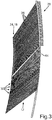
- Fig. 3 shows a schematic side view of a further exemplary embodiment of the lamellar seal 10 according to the invention.
- Fig. 3 is summarized below with 4 and 5 are explained, whereby Fig. 4 a perspective view of the in Fig. 3 shown lamellar seal 10 and Fig. 5 an increase in the Fig. 4 shown details V.
- Fig. 4 a perspective view of the in Fig. 3 shown lamellar seal 10 and Fig. 5 an increase in the Fig. 4 shown details V.
- some of the slats 12 have upstream and downstream winglets 30, that is to say they have lateral end regions which are set forward or backward at a respective angle of attack.
- the winglets 30 can basically have any geometries and surfaces. It can also be provided that the upstream and / or downstream winglets 30 have different angles of attack.
- the slats 12 with winglets 30 also have a greater width than those slats 12 which were manufactured without winglets 30.
- all slats 12 can have the same width or slats 12 without winglets 30 can have a greater width than slats 12 with winglets 30.
- the winglets 30 increase the sealing effect of the lamellar seal 10, since they partially block the passage for the gas flow which is straight through in the axial direction and deflect the gas flow. As a result, they represent a kind of labyrinth seal, whereby it should be emphasized that there is always a certain residual gap between the individual fins 12 - with or without winglet (s) 30.
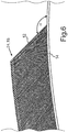
- Fig. 6 shows a schematic side view of a further embodiment of the lamellar seal 10 according to the invention, in which the in Fig. 1 shown support structure 16 was removed. It can also be seen that the laying angle ⁇ of the lamellae 12 in comparison with Fig. 1 is selected differently in order to ensure better adaptation to a different installation situation of the lamellar seal 10.
Landscapes
- Engineering & Computer Science (AREA)
- General Engineering & Computer Science (AREA)
- Mechanical Engineering (AREA)
- Turbine Rotor Nozzle Sealing (AREA)
- Sealing Using Fluids, Sealing Without Contact, And Removal Of Oil (AREA)
Claims (13)
- Joint à lamelles (10) destiné à assurer l'étanchéité d'un arbre tournant autour d'un axe, en particulier dans une turbine à gaz, comprenant une pluralité de lamelles (12) disposées à distance les unes des autres, les lamelles (12) étant fabriquées d'un seul tenant avec un élément de base (14) portant les lamelles (12) au moyen d'un procédé de fabrication générative, caractérisé en ce qu'au moins une lamelle (12) présente une géométrie de section transversale irrégulière, et en ce que l'au moins une lamelle (12) présente une épaisseur de section transversale réduite dans la zone de l'élément de base (14).
- Joint à lamelles (10) selon la revendication 1, caractérisé en ce qu'au moins une lamelle (12) comprend un élément d'écartement (24) pour le réglage d'une distance minimale par rapport à une lamelle (12) adjacente.
- Joint à lamelles (10) selon la revendication 1 ou 2, caractérisé en ce qu'au moins une lamelle (12) est disposée selon un angle de pose (a) prédéfini et/ou selon un angle d'incidence prédéfini par rapport à un axe longitudinal de l'élément de base (14).
- Joint à lamelles (10) selon l'une des revendications 1 à 3, caractérisé en ce que l'élément de base (14) comprend au moins un moyen de fixation (28) pour la fixation du joint à lamelles (10) à un composant, en particulier à une partie de carter.
- Joint à lamelles (10) selon la revendication 4, caractérisé en ce que l'au moins un moyen de fixation (28) est disposé sur un côté de l'élément de base (14) opposé aux lamelles (12).
- Joint à lamelles (10) selon la revendication 4 ou 5, caractérisé en ce que l'au moins un moyen de fixation (28) est fabriqué d'un seul tenant avec l'élément de base (14) au moyen du procédé de fabrication générative.
- Joint à lamelles (10) selon l'une des revendications 1 à 6, caractérisé en ce qu'au moins une lamelle (12) comporte une ailette (30) dans sa zone d'extrémité amont et/ou aval.
- Joint à lamelles (10) selon l'une des revendications 1 à 7, caractérisé en ce que l'élément de base (14) et/ou au moins une lamelle (12) comporte au moins un évidement.
- Joint à lamelles (10) selon l'une des revendications 1 à 8, caractérisé en ce que l'élément de base (14) est élastiquement déformable et/ou est réalisé sous la forme d'un segment annulaire en section longitudinale.
- Turbine à gaz, en particulier moteur d'aéronef, comprenant un carter dans lequel au moins un joint à lamelles (10) selon l'une des revendications 1 à 9 est disposé autour d'un rotor afin de réduire un écoulement de fluide d'un côté haute pression à un côté basse pression du rotor.
- Turbine à gaz selon la revendication 10, caractérisée en ce qu'au moins deux joints à lamelles (10) sont prévus, lesquels joints à lamelles sont disposés en série, de préférence décalés dans la direction axiale par rapport à un axe de rotation du rotor.
- Procédé de fabrication d'un joint à lamelles (10) destiné à assurer l'étanchéité d'un arbre tournant autour d'un axe, en particulier dans une turbine à gaz, le joint à lamelles (10) comprenant une pluralité de lamelles (12) disposées à distance les unes des autres, caractérisé en ce que les lamelles (12) sont fabriquées d'un seul tenant avec un élément de base (14) portant les lamelles (12) au moyen d'un procédé de fabrication générative, caractérisé en ce que, pendant le procédé de fabrication générative, une structure de support (16) est réalisée au niveau du joint à lamelles (10) et de préférence est ensuite enlevée.
- Procédé selon la revendication 12, caractérisé en ce que la structure de support est réalisée en même temps dans une zone d'extrémité des lamelles opposée à l'élément de base.
Priority Applications (2)
| Application Number | Priority Date | Filing Date | Title |
|---|---|---|---|
| EP14179331.5A EP2980460B1 (fr) | 2014-07-31 | 2014-07-31 | Construction et fabrication générative d'un joint intégral |
| US14/814,326 US10436052B2 (en) | 2014-07-31 | 2015-07-30 | Leaf seal for sealing off a shaft rotating around an axis |
Applications Claiming Priority (1)
| Application Number | Priority Date | Filing Date | Title |
|---|---|---|---|
| EP14179331.5A EP2980460B1 (fr) | 2014-07-31 | 2014-07-31 | Construction et fabrication générative d'un joint intégral |
Publications (2)
| Publication Number | Publication Date |
|---|---|
| EP2980460A1 EP2980460A1 (fr) | 2016-02-03 |
| EP2980460B1 true EP2980460B1 (fr) | 2020-04-01 |
Family
ID=51260684
Family Applications (1)
| Application Number | Title | Priority Date | Filing Date |
|---|---|---|---|
| EP14179331.5A Active EP2980460B1 (fr) | 2014-07-31 | 2014-07-31 | Construction et fabrication générative d'un joint intégral |
Country Status (2)
| Country | Link |
|---|---|
| US (1) | US10436052B2 (fr) |
| EP (1) | EP2980460B1 (fr) |
Citations (1)
| Publication number | Priority date | Publication date | Assignee | Title |
|---|---|---|---|---|
| DE102010054113A1 (de) * | 2010-12-10 | 2012-06-14 | Mtu Aero Engines Gmbh | Verfahren zur Herstellung einer Dichtung, Dichtung und Strömungsmaschine |
Family Cites Families (13)
| Publication number | Priority date | Publication date | Assignee | Title |
|---|---|---|---|---|
| US4526509A (en) * | 1983-08-26 | 1985-07-02 | General Electric Company | Rub tolerant shroud |
| US5031922A (en) * | 1989-12-21 | 1991-07-16 | Allied-Signal Inc. | Bidirectional finger seal |
| US5755445A (en) * | 1996-08-23 | 1998-05-26 | Alliedsignal Inc. | Noncontacting finger seal with hydrodynamic foot portion |
| US7077573B2 (en) * | 2001-06-11 | 2006-07-18 | Tribotek, Inc. | Contact bearing |
| JP4689882B2 (ja) * | 2001-06-29 | 2011-05-25 | イーグル工業株式会社 | 板ブラシシール装置 |
| US6736401B2 (en) * | 2001-12-19 | 2004-05-18 | Honeywell International, Inc. | Laminated finger seal with ceramic composition |
| JP4054607B2 (ja) * | 2002-05-23 | 2008-02-27 | イーグル工業株式会社 | 板ブラシシール |
| US7744093B2 (en) * | 2002-08-23 | 2010-06-29 | Rolls-Royce Plc | Seals and a method of making seals |
| DE102004020378A1 (de) | 2004-04-23 | 2005-11-10 | Alstom Technology Ltd | Lamellendichtung, insbesondere für eine Gasturbine, sowie Verfahren zu deren Herstellung |
| JP3970298B2 (ja) * | 2005-11-10 | 2007-09-05 | 三菱重工業株式会社 | 軸シール機構 |
| US7735833B2 (en) * | 2006-11-14 | 2010-06-15 | The University Of Akron | Double padded finger seal |
| US8333544B1 (en) * | 2009-08-14 | 2012-12-18 | Florida Turbine Technologies, Inc. | Card seal for a turbomachine |
| US9512922B2 (en) * | 2009-11-24 | 2016-12-06 | Honeywell International Inc. | Sealing apparatus and engines |
-
2014
- 2014-07-31 EP EP14179331.5A patent/EP2980460B1/fr active Active
-
2015
- 2015-07-30 US US14/814,326 patent/US10436052B2/en not_active Expired - Fee Related
Patent Citations (1)
| Publication number | Priority date | Publication date | Assignee | Title |
|---|---|---|---|---|
| DE102010054113A1 (de) * | 2010-12-10 | 2012-06-14 | Mtu Aero Engines Gmbh | Verfahren zur Herstellung einer Dichtung, Dichtung und Strömungsmaschine |
Also Published As
| Publication number | Publication date |
|---|---|
| US10436052B2 (en) | 2019-10-08 |
| EP2980460A1 (fr) | 2016-02-03 |
| US20160032749A1 (en) | 2016-02-04 |
Similar Documents
| Publication | Publication Date | Title |
|---|---|---|
| EP1743108B1 (fr) | Garniture d'étanchéité lamellaire, notamment pour turbine à gaz, et procédé permettant de la produire | |
| EP1595058B1 (fr) | Systeme de joint notamment destine a des segments d'ailettes de turbines a gaz | |
| EP2593644B1 (fr) | Élément d'étanchéité pour étanchéifier une fente | |
| EP2659158B1 (fr) | Disque de frein et procédé servant à traiter la surface d'un disque de frein | |
| DE102014208801A1 (de) | Dichtung, Verfahren zur Herstellung einer Dichtung und Strömungsmaschine | |
| EP3237769B1 (fr) | Palier-feuille, procédé pour ajuster une géométrie d'intervalle d'un palier-feuille et procédé approprié de fabrication d'un palier-feuille | |
| DE60307100T2 (de) | Dichtungsanordnung für den rotor einer turbomaschine | |
| DE102010041808A1 (de) | Schaufelkranzsegment, Strömungsmaschine sowie Verfahren zu deren Herstellung | |
| EP2960555B1 (fr) | Système de joint à brosse pour sceller un intervalle entre les éléments d'une turbomachine qui peuvent être déplacés les uns par rapport aux autres | |
| EP2344722A2 (fr) | Groupe d'aubes avec pied de montage axial décalé | |
| DE102011102598A1 (de) | Verfahren zur Herstellung einer Wabendichtung, Wabendichtung sowie Strömungsmaschine | |
| EP2857721B1 (fr) | Système de joint balai destiné à étanchéifier une fente entre des composants mobiles les uns par rapport aux autres d'une turbine à gaz thermique | |
| EP1918588B1 (fr) | Disque de stator pour une pompe turbomoléculaire | |
| EP2577117B1 (fr) | Procédé pour fixer un élément d'étanchéité à brosse dans une rainure d'un segment de boîtier | |
| EP2980460B1 (fr) | Construction et fabrication générative d'un joint intégral | |
| EP3312388B1 (fr) | Pièce de rotor, compresseur, turbine et procédé de fabrication associés | |
| EP1507958A1 (fr) | Dispositif de securite axial pour aubes mobiles | |
| DE102008038038A1 (de) | Laufschaufelsystem für eine Laufschaufelreihe einer Strömungsmaschine | |
| EP3425170A2 (fr) | Élément d'étanchéité pour turbomachines | |
| EP3290642A1 (fr) | Segment annulaire de turbine et systeme destine a la delimitation exterieure d'un trajet d'ecoulement d'une turbine | |
| EP2787175B1 (fr) | Système de sécurité et procédé de sécurité d'une zone de fixation d'au moins une aube de rotor ou d'un segment d'aube de rotor dans une zone de montage d'un palier de rotor | |
| EP3140554B1 (fr) | Élément de fixation, en particulier pour soufflets, présentant une zone de contredépouille intérieure | |
| DE102014200644A1 (de) | Strangprofil zur Herstellung einer Schaufel eines Nachleitrads | |
| EP3658770A1 (fr) | Segment annulaire de tour en acier pour éoliennes et procédé | |
| WO2012089377A1 (fr) | Outil de coupe pour produire au moins une dépression dans une surface, en particulier dans la surface d'un disque de frein |
Legal Events
| Date | Code | Title | Description |
|---|---|---|---|
| PUAI | Public reference made under article 153(3) epc to a published international application that has entered the european phase |
Free format text: ORIGINAL CODE: 0009012 |
|
| AK | Designated contracting states |
Kind code of ref document: A1 Designated state(s): AL AT BE BG CH CY CZ DE DK EE ES FI FR GB GR HR HU IE IS IT LI LT LU LV MC MK MT NL NO PL PT RO RS SE SI SK SM TR |
|
| AX | Request for extension of the european patent |
Extension state: BA ME |
|
| 17P | Request for examination filed |
Effective date: 20160628 |
|
| RBV | Designated contracting states (corrected) |
Designated state(s): AL AT BE BG CH CY CZ DE DK EE ES FI FR GB GR HR HU IE IS IT LI LT LU LV MC MK MT NL NO PL PT RO RS SE SI SK SM TR |
|
| REG | Reference to a national code |
Ref country code: DE Ref legal event code: R079 Ref document number: 502014013880 Country of ref document: DE Free format text: PREVIOUS MAIN CLASS: F16J0015320000 Ipc: F16J0015329200 |
|
| RIC1 | Information provided on ipc code assigned before grant |
Ipc: B22F 3/105 20060101ALI20180619BHEP Ipc: F01D 11/00 20060101ALI20180619BHEP Ipc: F16J 15/3292 20160101AFI20180619BHEP |
|
| STAA | Information on the status of an ep patent application or granted ep patent |
Free format text: STATUS: EXAMINATION IS IN PROGRESS |
|
| 17Q | First examination report despatched |
Effective date: 20181203 |
|
| GRAP | Despatch of communication of intention to grant a patent |
Free format text: ORIGINAL CODE: EPIDOSNIGR1 |
|
| STAA | Information on the status of an ep patent application or granted ep patent |
Free format text: STATUS: GRANT OF PATENT IS INTENDED |
|
| INTG | Intention to grant announced |
Effective date: 20191106 |
|
| GRAS | Grant fee paid |
Free format text: ORIGINAL CODE: EPIDOSNIGR3 |
|
| GRAA | (expected) grant |
Free format text: ORIGINAL CODE: 0009210 |
|
| STAA | Information on the status of an ep patent application or granted ep patent |
Free format text: STATUS: THE PATENT HAS BEEN GRANTED |
|
| AK | Designated contracting states |
Kind code of ref document: B1 Designated state(s): AL AT BE BG CH CY CZ DE DK EE ES FI FR GB GR HR HU IE IS IT LI LT LU LV MC MK MT NL NO PL PT RO RS SE SI SK SM TR |
|
| REG | Reference to a national code |
Ref country code: GB Ref legal event code: FG4D Free format text: NOT ENGLISH |
|
| REG | Reference to a national code |
Ref country code: CH Ref legal event code: EP Ref country code: AT Ref legal event code: REF Ref document number: 1251765 Country of ref document: AT Kind code of ref document: T Effective date: 20200415 |
|
| REG | Reference to a national code |
Ref country code: DE Ref legal event code: R096 Ref document number: 502014013880 Country of ref document: DE |
|
| REG | Reference to a national code |
Ref country code: IE Ref legal event code: FG4D Free format text: LANGUAGE OF EP DOCUMENT: GERMAN |
|
| PG25 | Lapsed in a contracting state [announced via postgrant information from national office to epo] |
Ref country code: BG Free format text: LAPSE BECAUSE OF FAILURE TO SUBMIT A TRANSLATION OF THE DESCRIPTION OR TO PAY THE FEE WITHIN THE PRESCRIBED TIME-LIMIT Effective date: 20200701 |
|
| REG | Reference to a national code |
Ref country code: NL Ref legal event code: MP Effective date: 20200401 |
|
| REG | Reference to a national code |
Ref country code: LT Ref legal event code: MG4D |
|
| PG25 | Lapsed in a contracting state [announced via postgrant information from national office to epo] |
Ref country code: PT Free format text: LAPSE BECAUSE OF FAILURE TO SUBMIT A TRANSLATION OF THE DESCRIPTION OR TO PAY THE FEE WITHIN THE PRESCRIBED TIME-LIMIT Effective date: 20200817 Ref country code: LT Free format text: LAPSE BECAUSE OF FAILURE TO SUBMIT A TRANSLATION OF THE DESCRIPTION OR TO PAY THE FEE WITHIN THE PRESCRIBED TIME-LIMIT Effective date: 20200401 Ref country code: GR Free format text: LAPSE BECAUSE OF FAILURE TO SUBMIT A TRANSLATION OF THE DESCRIPTION OR TO PAY THE FEE WITHIN THE PRESCRIBED TIME-LIMIT Effective date: 20200702 Ref country code: NO Free format text: LAPSE BECAUSE OF FAILURE TO SUBMIT A TRANSLATION OF THE DESCRIPTION OR TO PAY THE FEE WITHIN THE PRESCRIBED TIME-LIMIT Effective date: 20200701 Ref country code: FI Free format text: LAPSE BECAUSE OF FAILURE TO SUBMIT A TRANSLATION OF THE DESCRIPTION OR TO PAY THE FEE WITHIN THE PRESCRIBED TIME-LIMIT Effective date: 20200401 Ref country code: IS Free format text: LAPSE BECAUSE OF FAILURE TO SUBMIT A TRANSLATION OF THE DESCRIPTION OR TO PAY THE FEE WITHIN THE PRESCRIBED TIME-LIMIT Effective date: 20200801 Ref country code: SE Free format text: LAPSE BECAUSE OF FAILURE TO SUBMIT A TRANSLATION OF THE DESCRIPTION OR TO PAY THE FEE WITHIN THE PRESCRIBED TIME-LIMIT Effective date: 20200401 Ref country code: CZ Free format text: LAPSE BECAUSE OF FAILURE TO SUBMIT A TRANSLATION OF THE DESCRIPTION OR TO PAY THE FEE WITHIN THE PRESCRIBED TIME-LIMIT Effective date: 20200401 Ref country code: NL Free format text: LAPSE BECAUSE OF FAILURE TO SUBMIT A TRANSLATION OF THE DESCRIPTION OR TO PAY THE FEE WITHIN THE PRESCRIBED TIME-LIMIT Effective date: 20200401 |
|
| PG25 | Lapsed in a contracting state [announced via postgrant information from national office to epo] |
Ref country code: RS Free format text: LAPSE BECAUSE OF FAILURE TO SUBMIT A TRANSLATION OF THE DESCRIPTION OR TO PAY THE FEE WITHIN THE PRESCRIBED TIME-LIMIT Effective date: 20200401 Ref country code: HR Free format text: LAPSE BECAUSE OF FAILURE TO SUBMIT A TRANSLATION OF THE DESCRIPTION OR TO PAY THE FEE WITHIN THE PRESCRIBED TIME-LIMIT Effective date: 20200401 Ref country code: LV Free format text: LAPSE BECAUSE OF FAILURE TO SUBMIT A TRANSLATION OF THE DESCRIPTION OR TO PAY THE FEE WITHIN THE PRESCRIBED TIME-LIMIT Effective date: 20200401 |
|
| PG25 | Lapsed in a contracting state [announced via postgrant information from national office to epo] |
Ref country code: AL Free format text: LAPSE BECAUSE OF FAILURE TO SUBMIT A TRANSLATION OF THE DESCRIPTION OR TO PAY THE FEE WITHIN THE PRESCRIBED TIME-LIMIT Effective date: 20200401 |
|
| REG | Reference to a national code |
Ref country code: DE Ref legal event code: R097 Ref document number: 502014013880 Country of ref document: DE |
|
| PG25 | Lapsed in a contracting state [announced via postgrant information from national office to epo] |
Ref country code: IT Free format text: LAPSE BECAUSE OF FAILURE TO SUBMIT A TRANSLATION OF THE DESCRIPTION OR TO PAY THE FEE WITHIN THE PRESCRIBED TIME-LIMIT Effective date: 20200401 Ref country code: DK Free format text: LAPSE BECAUSE OF FAILURE TO SUBMIT A TRANSLATION OF THE DESCRIPTION OR TO PAY THE FEE WITHIN THE PRESCRIBED TIME-LIMIT Effective date: 20200401 Ref country code: SM Free format text: LAPSE BECAUSE OF FAILURE TO SUBMIT A TRANSLATION OF THE DESCRIPTION OR TO PAY THE FEE WITHIN THE PRESCRIBED TIME-LIMIT Effective date: 20200401 Ref country code: EE Free format text: LAPSE BECAUSE OF FAILURE TO SUBMIT A TRANSLATION OF THE DESCRIPTION OR TO PAY THE FEE WITHIN THE PRESCRIBED TIME-LIMIT Effective date: 20200401 Ref country code: RO Free format text: LAPSE BECAUSE OF FAILURE TO SUBMIT A TRANSLATION OF THE DESCRIPTION OR TO PAY THE FEE WITHIN THE PRESCRIBED TIME-LIMIT Effective date: 20200401 Ref country code: ES Free format text: LAPSE BECAUSE OF FAILURE TO SUBMIT A TRANSLATION OF THE DESCRIPTION OR TO PAY THE FEE WITHIN THE PRESCRIBED TIME-LIMIT Effective date: 20200401 |
|
| PLBE | No opposition filed within time limit |
Free format text: ORIGINAL CODE: 0009261 |
|
| STAA | Information on the status of an ep patent application or granted ep patent |
Free format text: STATUS: NO OPPOSITION FILED WITHIN TIME LIMIT |
|
| PG25 | Lapsed in a contracting state [announced via postgrant information from national office to epo] |
Ref country code: SK Free format text: LAPSE BECAUSE OF FAILURE TO SUBMIT A TRANSLATION OF THE DESCRIPTION OR TO PAY THE FEE WITHIN THE PRESCRIBED TIME-LIMIT Effective date: 20200401 Ref country code: MC Free format text: LAPSE BECAUSE OF FAILURE TO SUBMIT A TRANSLATION OF THE DESCRIPTION OR TO PAY THE FEE WITHIN THE PRESCRIBED TIME-LIMIT Effective date: 20200401 Ref country code: PL Free format text: LAPSE BECAUSE OF FAILURE TO SUBMIT A TRANSLATION OF THE DESCRIPTION OR TO PAY THE FEE WITHIN THE PRESCRIBED TIME-LIMIT Effective date: 20200401 |
|
| REG | Reference to a national code |
Ref country code: CH Ref legal event code: PL |
|
| 26N | No opposition filed |
Effective date: 20210112 |
|
| REG | Reference to a national code |
Ref country code: BE Ref legal event code: MM Effective date: 20200731 |
|
| PG25 | Lapsed in a contracting state [announced via postgrant information from national office to epo] |
Ref country code: LU Free format text: LAPSE BECAUSE OF NON-PAYMENT OF DUE FEES Effective date: 20200731 Ref country code: LI Free format text: LAPSE BECAUSE OF NON-PAYMENT OF DUE FEES Effective date: 20200731 Ref country code: CH Free format text: LAPSE BECAUSE OF NON-PAYMENT OF DUE FEES Effective date: 20200731 |
|
| PG25 | Lapsed in a contracting state [announced via postgrant information from national office to epo] |
Ref country code: SI Free format text: LAPSE BECAUSE OF FAILURE TO SUBMIT A TRANSLATION OF THE DESCRIPTION OR TO PAY THE FEE WITHIN THE PRESCRIBED TIME-LIMIT Effective date: 20200401 Ref country code: BE Free format text: LAPSE BECAUSE OF NON-PAYMENT OF DUE FEES Effective date: 20200731 |
|
| PG25 | Lapsed in a contracting state [announced via postgrant information from national office to epo] |
Ref country code: IE Free format text: LAPSE BECAUSE OF NON-PAYMENT OF DUE FEES Effective date: 20200731 |
|
| REG | Reference to a national code |
Ref country code: AT Ref legal event code: MM01 Ref document number: 1251765 Country of ref document: AT Kind code of ref document: T Effective date: 20200731 |
|
| PG25 | Lapsed in a contracting state [announced via postgrant information from national office to epo] |
Ref country code: AT Free format text: LAPSE BECAUSE OF NON-PAYMENT OF DUE FEES Effective date: 20200731 |
|
| PGFP | Annual fee paid to national office [announced via postgrant information from national office to epo] |
Ref country code: FR Payment date: 20210722 Year of fee payment: 8 |
|
| PGFP | Annual fee paid to national office [announced via postgrant information from national office to epo] |
Ref country code: GB Payment date: 20210722 Year of fee payment: 8 Ref country code: DE Payment date: 20210721 Year of fee payment: 8 |
|
| PG25 | Lapsed in a contracting state [announced via postgrant information from national office to epo] |
Ref country code: TR Free format text: LAPSE BECAUSE OF FAILURE TO SUBMIT A TRANSLATION OF THE DESCRIPTION OR TO PAY THE FEE WITHIN THE PRESCRIBED TIME-LIMIT Effective date: 20200401 Ref country code: MT Free format text: LAPSE BECAUSE OF FAILURE TO SUBMIT A TRANSLATION OF THE DESCRIPTION OR TO PAY THE FEE WITHIN THE PRESCRIBED TIME-LIMIT Effective date: 20200401 Ref country code: CY Free format text: LAPSE BECAUSE OF FAILURE TO SUBMIT A TRANSLATION OF THE DESCRIPTION OR TO PAY THE FEE WITHIN THE PRESCRIBED TIME-LIMIT Effective date: 20200401 |
|
| PG25 | Lapsed in a contracting state [announced via postgrant information from national office to epo] |
Ref country code: MK Free format text: LAPSE BECAUSE OF FAILURE TO SUBMIT A TRANSLATION OF THE DESCRIPTION OR TO PAY THE FEE WITHIN THE PRESCRIBED TIME-LIMIT Effective date: 20200401 |
|
| REG | Reference to a national code |
Ref country code: DE Ref legal event code: R119 Ref document number: 502014013880 Country of ref document: DE |
|
| GBPC | Gb: european patent ceased through non-payment of renewal fee |
Effective date: 20220731 |
|
| PG25 | Lapsed in a contracting state [announced via postgrant information from national office to epo] |
Ref country code: FR Free format text: LAPSE BECAUSE OF NON-PAYMENT OF DUE FEES Effective date: 20220731 |
|
| PG25 | Lapsed in a contracting state [announced via postgrant information from national office to epo] |
Ref country code: GB Free format text: LAPSE BECAUSE OF NON-PAYMENT OF DUE FEES Effective date: 20220731 Ref country code: DE Free format text: LAPSE BECAUSE OF NON-PAYMENT OF DUE FEES Effective date: 20230201 |