EP2857733B1 - Kombination umfassend ein Schlauchanschlussteil, einen Schlauchstutzen und eine Mutter - Google Patents
Kombination umfassend ein Schlauchanschlussteil, einen Schlauchstutzen und eine Mutter Download PDFInfo
- Publication number
- EP2857733B1 EP2857733B1 EP13187120.4A EP13187120A EP2857733B1 EP 2857733 B1 EP2857733 B1 EP 2857733B1 EP 13187120 A EP13187120 A EP 13187120A EP 2857733 B1 EP2857733 B1 EP 2857733B1
- Authority
- EP
- European Patent Office
- Prior art keywords
- nut
- hose
- attachment part
- clamping
- structural element
- Prior art date
- Legal status (The legal status is an assumption and is not a legal conclusion. Google has not performed a legal analysis and makes no representation as to the accuracy of the status listed.)
- Active
Links
Images


Classifications
-
- F—MECHANICAL ENGINEERING; LIGHTING; HEATING; WEAPONS; BLASTING
- F16—ENGINEERING ELEMENTS AND UNITS; GENERAL MEASURES FOR PRODUCING AND MAINTAINING EFFECTIVE FUNCTIONING OF MACHINES OR INSTALLATIONS; THERMAL INSULATION IN GENERAL
- F16L—PIPES; JOINTS OR FITTINGS FOR PIPES; SUPPORTS FOR PIPES, CABLES OR PROTECTIVE TUBING; MEANS FOR THERMAL INSULATION IN GENERAL
- F16L33/00—Arrangements for connecting hoses to rigid members; Rigid hose-connectors, i.e. single members engaging both hoses
- F16L33/22—Arrangements for connecting hoses to rigid members; Rigid hose-connectors, i.e. single members engaging both hoses with means not mentioned in the preceding groups for gripping the hose between inner and outer parts
- F16L33/225—Arrangements for connecting hoses to rigid members; Rigid hose-connectors, i.e. single members engaging both hoses with means not mentioned in the preceding groups for gripping the hose between inner and outer parts a sleeve being movable axially
- F16L33/226—Arrangements for connecting hoses to rigid members; Rigid hose-connectors, i.e. single members engaging both hoses with means not mentioned in the preceding groups for gripping the hose between inner and outer parts a sleeve being movable axially the sleeve being screwed over the hose
-
- F—MECHANICAL ENGINEERING; LIGHTING; HEATING; WEAPONS; BLASTING
- F16—ENGINEERING ELEMENTS AND UNITS; GENERAL MEASURES FOR PRODUCING AND MAINTAINING EFFECTIVE FUNCTIONING OF MACHINES OR INSTALLATIONS; THERMAL INSULATION IN GENERAL
- F16L—PIPES; JOINTS OR FITTINGS FOR PIPES; SUPPORTS FOR PIPES, CABLES OR PROTECTIVE TUBING; MEANS FOR THERMAL INSULATION IN GENERAL
- F16L19/00—Joints in which sealing surfaces are pressed together by means of a member, e.g. a swivel nut, screwed on, or into, one of the joint parts
- F16L19/005—Joints in which sealing surfaces are pressed together by means of a member, e.g. a swivel nut, screwed on, or into, one of the joint parts comprising locking means for the threaded member
-
- B—PERFORMING OPERATIONS; TRANSPORTING
- B67—OPENING, CLOSING OR CLEANING BOTTLES, JARS OR SIMILAR CONTAINERS; LIQUID HANDLING
- B67D—DISPENSING, DELIVERING OR TRANSFERRING LIQUIDS, NOT OTHERWISE PROVIDED FOR
- B67D7/00—Apparatus or devices for transferring liquids from bulk storage containers or reservoirs into vehicles or into portable containers, e.g. for retail sale purposes
- B67D7/06—Details or accessories
- B67D7/32—Arrangements of safety or warning devices; Means for preventing unauthorised delivery of liquid
- B67D7/3281—Details
-
- F—MECHANICAL ENGINEERING; LIGHTING; HEATING; WEAPONS; BLASTING
- F16—ENGINEERING ELEMENTS AND UNITS; GENERAL MEASURES FOR PRODUCING AND MAINTAINING EFFECTIVE FUNCTIONING OF MACHINES OR INSTALLATIONS; THERMAL INSULATION IN GENERAL
- F16L—PIPES; JOINTS OR FITTINGS FOR PIPES; SUPPORTS FOR PIPES, CABLES OR PROTECTIVE TUBING; MEANS FOR THERMAL INSULATION IN GENERAL
- F16L19/00—Joints in which sealing surfaces are pressed together by means of a member, e.g. a swivel nut, screwed on, or into, one of the joint parts
- F16L19/06—Joints in which sealing surfaces are pressed together by means of a member, e.g. a swivel nut, screwed on, or into, one of the joint parts in which radial clamping is obtained by wedging action on non-deformed pipe ends
- F16L19/065—Joints in which sealing surfaces are pressed together by means of a member, e.g. a swivel nut, screwed on, or into, one of the joint parts in which radial clamping is obtained by wedging action on non-deformed pipe ends the wedging action being effected by means of a ring
- F16L19/0656—Joints in which sealing surfaces are pressed together by means of a member, e.g. a swivel nut, screwed on, or into, one of the joint parts in which radial clamping is obtained by wedging action on non-deformed pipe ends the wedging action being effected by means of a ring integral with one of the connecting parts
-
- F—MECHANICAL ENGINEERING; LIGHTING; HEATING; WEAPONS; BLASTING
- F16—ENGINEERING ELEMENTS AND UNITS; GENERAL MEASURES FOR PRODUCING AND MAINTAINING EFFECTIVE FUNCTIONING OF MACHINES OR INSTALLATIONS; THERMAL INSULATION IN GENERAL
- F16L—PIPES; JOINTS OR FITTINGS FOR PIPES; SUPPORTS FOR PIPES, CABLES OR PROTECTIVE TUBING; MEANS FOR THERMAL INSULATION IN GENERAL
- F16L25/00—Construction or details of pipe joints not provided for in, or of interest apart from, groups F16L13/00 - F16L23/00
- F16L25/01—Construction or details of pipe joints not provided for in, or of interest apart from, groups F16L13/00 - F16L23/00 specially adapted for realising electrical conduction between the two pipe ends of the joint or between parts thereof
-
- F—MECHANICAL ENGINEERING; LIGHTING; HEATING; WEAPONS; BLASTING
- F16—ENGINEERING ELEMENTS AND UNITS; GENERAL MEASURES FOR PRODUCING AND MAINTAINING EFFECTIVE FUNCTIONING OF MACHINES OR INSTALLATIONS; THERMAL INSULATION IN GENERAL
- F16L—PIPES; JOINTS OR FITTINGS FOR PIPES; SUPPORTS FOR PIPES, CABLES OR PROTECTIVE TUBING; MEANS FOR THERMAL INSULATION IN GENERAL
- F16L33/00—Arrangements for connecting hoses to rigid members; Rigid hose-connectors, i.e. single members engaging both hoses
- F16L33/22—Arrangements for connecting hoses to rigid members; Rigid hose-connectors, i.e. single members engaging both hoses with means not mentioned in the preceding groups for gripping the hose between inner and outer parts
- F16L33/223—Arrangements for connecting hoses to rigid members; Rigid hose-connectors, i.e. single members engaging both hoses with means not mentioned in the preceding groups for gripping the hose between inner and outer parts the sealing surfaces being pressed together by means of a member, e.g. a swivel nut, screwed on or into one of the joint parts
-
- F—MECHANICAL ENGINEERING; LIGHTING; HEATING; WEAPONS; BLASTING
- F16—ENGINEERING ELEMENTS AND UNITS; GENERAL MEASURES FOR PRODUCING AND MAINTAINING EFFECTIVE FUNCTIONING OF MACHINES OR INSTALLATIONS; THERMAL INSULATION IN GENERAL
- F16L—PIPES; JOINTS OR FITTINGS FOR PIPES; SUPPORTS FOR PIPES, CABLES OR PROTECTIVE TUBING; MEANS FOR THERMAL INSULATION IN GENERAL
- F16L39/00—Joints or fittings for double-walled or multi-channel pipes or pipe assemblies
- F16L39/02—Joints or fittings for double-walled or multi-channel pipes or pipe assemblies for hoses
-
- B—PERFORMING OPERATIONS; TRANSPORTING
- B67—OPENING, CLOSING OR CLEANING BOTTLES, JARS OR SIMILAR CONTAINERS; LIQUID HANDLING
- B67D—DISPENSING, DELIVERING OR TRANSFERRING LIQUIDS, NOT OTHERWISE PROVIDED FOR
- B67D2210/00—Indexing scheme relating to aspects and details of apparatus or devices for dispensing beverages on draught or for controlling flow of liquids under gravity from storage containers for dispensing purposes
- B67D2210/00028—Constructional details
- B67D2210/00047—Piping
- B67D2210/00062—Pipe joints
-
- B—PERFORMING OPERATIONS; TRANSPORTING
- B67—OPENING, CLOSING OR CLEANING BOTTLES, JARS OR SIMILAR CONTAINERS; LIQUID HANDLING
- B67D—DISPENSING, DELIVERING OR TRANSFERRING LIQUIDS, NOT OTHERWISE PROVIDED FOR
- B67D7/00—Apparatus or devices for transferring liquids from bulk storage containers or reservoirs into vehicles or into portable containers, e.g. for retail sale purposes
- B67D7/04—Apparatus or devices for transferring liquids from bulk storage containers or reservoirs into vehicles or into portable containers, e.g. for retail sale purposes for transferring fuels, lubricants or mixed fuels and lubricants
- B67D7/0476—Vapour recovery systems
- B67D7/0478—Vapour recovery systems constructional features or components
-
- F—MECHANICAL ENGINEERING; LIGHTING; HEATING; WEAPONS; BLASTING
- F16—ENGINEERING ELEMENTS AND UNITS; GENERAL MEASURES FOR PRODUCING AND MAINTAINING EFFECTIVE FUNCTIONING OF MACHINES OR INSTALLATIONS; THERMAL INSULATION IN GENERAL
- F16B—DEVICES FOR FASTENING OR SECURING CONSTRUCTIONAL ELEMENTS OR MACHINE PARTS TOGETHER, e.g. NAILS, BOLTS, CIRCLIPS, CLAMPS, CLIPS OR WEDGES; JOINTS OR JOINTING
- F16B39/00—Locking of screws, bolts or nuts
- F16B39/22—Locking of screws, bolts or nuts in which the locking takes place during screwing down or tightening
- F16B39/28—Locking of screws, bolts or nuts in which the locking takes place during screwing down or tightening by special members on, or shape of, the nut or bolt
- F16B39/32—Locking by means of a pawl or pawl-like tongue
Definitions
- the invention relates to a combination according to the preamble of claim 1, comprising a hose nozzle for a fluid hose, a nut for placement on the hose nozzle and a hose connector for a fluid hose.
- the invention is in the field of hose connections.
- a typical hose connecting part has an internal thread, which can be liquid-tightly connected to a corresponding external thread of a hose nozzle.
- dispenser connections which have a fixed internal thread or a rotatable metal nut with internal thread. These can be connected to a hose nozzle with external thread liquid-tight.
- a disadvantage of a fixed internal thread is that the dispensing hose, which usually has a desired curvature, can not be aligned during assembly.
- the game of a rotatable nut with êtgwinde allows an orientation of the dispensing tube, but not its fixation in the desired orientation.
- the US 5,285,744 discloses a hose assembly for the fuel line to a fuel nozzle which allows complete rotation of the fuel nozzle relative to the connected hose.
- From the US Pat. No. 6,412,832 B1 is a fitting with a nut and a connection part known, between which a specially trained pipe end with a Groove can be pinched.
- the US Pat. No. 5,799,834 discloses a telescopic riser for connecting an electric submersible pump in a fuel storage tank with a distributor head.
- the EP 2 620 684 A1 relates to a device for connecting pipes and accessories, with a holding body with elastic radial elements and a cooperating with the holding body nut.
- GB 2 029 538 A discloses a tube fitting with an integrally molded lip, which simultaneously functions as a sealing joint and a mechanical anchoring ring.
- US 2012/001425 A1 relates to hydraulic connections with a male connection part and a female connection part, which have matched sealing surfaces.
- WO 89/10323 A1 discloses a hose assembly for a fuel line, with liquid and vapor recovery.
- document US 5,746,454 A discloses an underground piping system that interconnects coaxial tubes with a primary feed tube and a secondary containment tube such that the space between the two tubes can be connected to the space in other tube segments.
- the US 2011/0067779 A1 relates to vapor recovery valves.
- a nut according to the invention for placement on a hose nozzle has a connection device which can be connected to a hose connection part in a liquid-tight manner.
- This can be any suitable connection device known in the prior art.
- the connection device comprises an external thread which can be connected in a liquid-tight manner to a corresponding internal thread of the hose connection part.
- a nut according to the invention also has a receptacle for the hose nozzle, with a first end and a second end, wherein the receptacle is adapted to form-fit the hose nozzle in the circumferential direction, such that the nut and the hose nozzle are rotatable relative to each other in the circumferential direction.
- the terms circumferential direction, axial direction and radial direction refer in the context of the invention to the geometry of the nut, wherein the axial direction designates the direction parallel to the inner peripheral surface of the receptacle for the hose nozzle and transversely to the circumferential direction.
- the nut has an anti-rotation, which is designed so that by a structural element of the hose connection part of an open position in which the nut and the hose nozzle in the circumferential direction against each other are rotatable when the nut is arranged on the hose nozzle , Can be converted into a closed position in which a rotation of the nut in the circumferential direction relative to Hose nozzle is prevented when the nut is placed on the hose nozzle.
- open position and closed position are not limited to discrete states.
- the transition from the open position to the closed position can be fluid.
- the distinction between open position and closed position may depend on a certain torque required to cause the nut to rotate circumferentially relative to the hose nozzle.
- the term closed position also includes those embodiments of the invention in which rotation of the nut is prevented in the circumferential direction relative to the hose nozzle below a certain torque threshold, which is preferably chosen so that in normal use of the nut according to the invention, or of the hose nozzle according to the invention, a rotation of the nut in the circumferential direction is prevented relative to the hose nozzle.
- the torque threshold is preferably greater than 10 Nm, more preferably greater than 20 Nm, more preferably greater than 30 Nm, more preferably greater than 40 Nm.
- Further preferred torque threshold values in the context of the invention are in the range of 10 Nm to 50 Nm, more preferably in the range of 10 Nm to 40 Nm, more preferably in the range of 20 Nm to 30 Nm, particularly preferably in the range of 40 Nm to 50 Nm.
- the invention has recognized that a correspondingly designed anti-twist device allows easy alignment and fixing of the hose during assembly.
- a tube attached to the hose nozzle in the open position the torsion protection be aligned by the hose nozzle is rotated relative to the mother in the circumferential direction until the desired orientation is reached.
- the anti-twist protection can then be transferred from the open position to the closed position by cooperation of the nut with the hose connector part in order to fix the hose in the desired orientation.
- the nut is tuned to a hose connector as described above.
- the hose connection part can be a hose connection part for a fluid hose, preferably for a fluid hose, particularly preferably for a fuel nozzle, comprising a fluid channel at one end of which a connection device is arranged which allows a fluid-tight connection with the nut, the connection device each in the prior art, the connecting device preferably comprises an internal thread, which can be connected to a corresponding external thread of the nut, wherein the hose connecting part comprises a structural element which is adapted to the anti-rotation of the nut from an open position in to bring a closed position.
- the nut may in particular be adapted to a hose connector of the type described below. The statements below for the hose connector according to the invention express reference is made in the context of the mother to avoid repetition.
- the nut is tuned to a hose nozzle as described above.
- the hose nozzle may be a hose nozzle for a fluid hose, preferably for a liquid hose, particularly preferably for a fuel tap hose, with a pipe socket for attaching the fluid hose, wherein the outside of the hose nozzle has a support surface for the mother, wherein the dimensions of the hose nozzle are matched to the mother, that the hose nozzle of the nut form-fitting may be included, such that the hose nozzle and the nut are rotatable relative to each other in the circumferential direction.
- the mother may be particularly tuned to a hose nozzle of the type described below. In the context of the mother to avoid repetition, reference is expressly made to the below statements on the hose nozzle.
- the nut is preferably designed so that the anti-rotation is transferred at a certain point of the connection process between the nut and the hose connector by the structural element of the hose connector from the open position to the closed position when the mother is connected to the hose connector.
- This has the advantage that the fixation of the hose takes place at a certain point of the connection process. Preferably, this point is towards the end of the connection process.
- the nut is designed so that the anti-rotation device only then interacts with the structural element of the hose connection part in order to transfer the anti-rotation protection from the open position to the closed position when the nut is almost completely connected to the hose connection part.
- the connecting device of the nut is preferably arranged on the outside of the nut.
- the outer side of the nut designates that side of the nut which faces away from the hose nozzle when the nut is arranged on the hose nozzle.
- the inside of the nut in the invention refers to that side of the nut, which faces the hose nozzle when the nut is arranged on the hose nozzle.
- the anti-rotation is arranged on the inside of the nut. This facilitates the interaction of the anti-rotation with the hose nozzle. It is advantageous if the anti-rotation protection is arranged in the region of the connecting device. This facilitates the interaction of the nut with the hose connection part in order to transfer the twist protection from an open position into a closed position.
- both the anti-rotation and the connecting device of the nut are arranged in the region of the first end of the receptacle.
- the anti-rotation on the inside of the mother arranged in the region of the first end of the receptacle, wherein the anti-rotation protrude into the receptacle, and the connecting device is arranged on the outside of the nut in the region of the first end of the receptacle, wherein the connecting device is located outside of the receptacle.
- the interaction of the nut with the hose connection part may include the exertion of a force on the protection against rotation by the structural element of the hose connection part, in particular the exertion of a radial force.
- an advantageous embodiment of the invention provides that the anti-rotation at least one, preferably arranged on the inside of the nut, clamping element comprises, of an open position, which allows a rotational movement of the nut in the circumferential direction relative to the hose nozzle when the nut is arranged on the hose nozzle , Can be converted into a clamping position in which the clamping element, to prevent rotational movement of the nut in the circumferential direction relative to the hose nozzle, is pressed against the hose nozzle when the nut is arranged on the hose nozzle.
- open position and clamping position are not limited to discrete states.
- the transition from the open position to the clamping position can be fluid.
- the distinction between open position and clamping position may depend on a certain torque required to cause the nut to rotate in the circumferential direction relative to the hose nozzle.
- a certain torque threshold included in the frame the invention of the term clamping position and those embodiments of the invention in which rotation of the nut is prevented relative to the hose nozzle below a certain torque threshold, which is preferably selected so that in normal use of the nut according to the invention, or the hose nozzle according to the invention, a Turning the nut in the circumferential direction is prevented relative to the hose nozzle.
- the torque threshold is preferably greater than 10 Nm, more preferably greater than 20 Nm, more preferably greater than 30 Nm, more preferably greater than 40 Nm.
- Further preferred torque threshold values in the context of the invention are in the range of 10 Nm to 50 Nm, more preferably in the range of 10 Nm to 40 Nm, more preferably in the range of 20 Nm to 30 Nm, particularly preferably in the range of 40 Nm to 50 Nm.
- the at least one clamping element is dimensioned and arranged so that the structural element of the hose connection part can act directly on the clamping element. This allows a comparatively simple structural realization.
- the nut is designed so that the at least one clamping element is transferred at a certain point of the connection process between the nut and the hose connector by cooperating with the structural element of the hose connector from the open position to the clamping position when the nut is connected to the hose connector.
- This has the advantage that the fixation of the hose takes place at a certain point of the connection process. Preferably, this point is towards the end of the connection process.
- That at least a clamping element is preferably arranged and dimensioned such that it only then cooperates with the structural element of the hose connecting part, in order to transfer the clamping element from the clamping position into the open position, when the nut is almost completely connected to the hose connecting part.
- the latter has the advantage that the hose must be aligned only towards the end of the connection process and can be fixed with little effort in the desired orientation.
- the at least one clamping element is preferably designed to be held in the clamping position by means of a clamping force, preferably a radial clamping force.
- the at least one clamping element is adapted to be held by direct action of the structural element by means of a radial clamping force in the clamping position.
- the anti-rotation protection comprises at least two clamping elements.
- the clamping elements are spaced apart in the circumferential direction.
- the distances between the clamping elements can each be the same size.
- the anti-rotation device comprises 2 to 12, more preferably 4 to 8, most preferably 6 clamping elements, which may each be spaced apart in the circumferential direction.
- the connecting device comprises an external thread, which is liquid-tightly connectable to a corresponding internal thread of the hose connecting part, the clamping element or the clamping elements projecting beyond the external thread in the axial direction.
- the connecting device is arranged on the outside of the nut in the region of the first end of the receptacle and / or the clamping element or the clamping elements are arranged on the inside of the nut in the region of the first end of the receptacle.
- the clamping element or the clamping elements are arranged on the inside of the nut. This facilitates the interaction with the hose nozzle. It is advantageous if the clamping element or the clamping elements are arranged in the region of the connecting device. This facilitates the interaction of the clamping elements with the structural element of the hose connection part as a function of the connection process between the nut and the hose connection part.
- both the clamping element or the clamping elements and the connecting device of the nut are arranged in the region of the first end of the receptacle.
- the clamping element or the clamping elements is arranged on the inside of the nut in the region of the first end of the receptacle, wherein the clamping element or the clamping elements protrude into the receptacle, and the connecting device is arranged on the outside of the nut in the region of the first end of the receptacle , wherein the connecting device is located outside the receptacle.
- the nut may be made of plastic, preferably of an electrically conductive plastic, more preferably of an electrically conductive plastic having an electrical resistance according to EN 13617-2 less than 100 000 ohms, preferably with an electrical resistance according to EN 13617-2 between 200 and 1000 ohms ,
- the plastic is preferably selected from the group consisting of polyamides (PA) and polyetheretherketones (PEEK).
- the nut is preferably designed so that the connection between the nut and the hose connecting part withstands a tensile force of at least 2000 N for 2 minutes, preferably at least 2000 N for 5 minutes. Measure in accordance with EM 13483 Annex K, applying the force by pulling apart the terminals of the tester at a speed of (75 ⁇ 5) mm / min.
- the nut has reinforcing elements, wherein the reinforcing elements are preferably spaced apart in the circumferential direction and / or are preferably arranged on the inside of the nut, preferably in the region of the first end of the receptacle, and / or are preferably arranged in the vicinity of the connecting device.
- the arrangement of the reinforcing elements in the region of the connecting device serves to increase the tensile strength of the connection between the nut and the hose connecting part.
- the receptacle for the hose nozzle can advantageously extend over the entire axial extent of the nut.
- the nut is designed to be connected to a hose connection part for a fuel and / or gas hose, preferably with a dispenser connection, particularly preferably with a dispensing connection for a coaxial hose.
- the connecting device of the nut is designed such that it also allows a connection to a hose connecting part which does not have a structural element according to the invention.
- a connection allows only the alignment of the tube and not its fixation. But it allows a gradual retrofitting of existing hose connections by the hose connection is first retrofitted with a nut according to the invention and a hose nozzle according to the invention before retrofitting with a hose connection part according to the invention.
- the nut is used for placement on a hose nozzle and can be determined to this arrangement.
- the invention is not limited to any particular type of arrangement.
- the nut can be plugged onto a hose nozzle.
- the nut has at least one latching element which can cooperate with at least one retaining element of the hose nozzle to fix the nut on the hose nozzle in the axial direction and / or if at least one clamping element of the nut is designed as a latching element, so in that it can cooperate with at least one holding element of the hose nozzle in order to fix the nut on the hose nozzle in the axial direction.
- the nut can be designed as a polygonal nut, preferably as a triangular, square, hexagonal, octagonal or twelve-edged nut, particularly preferably as a hexagonal nut.
- the polygonal structure is arranged on the outside of the nut in the region of the second end of the receptacle.
- the invention also relates to a hose nozzle. This will be explained below.
- Hose sockets are known in the art. They have a passage for the fluid and usually a pipe socket for attaching the hose.
- the hose nozzle according to the invention is a hose nozzle for a fluid hose, preferably for a fluid hose, particularly preferably for a fuel nozzle, with a pipe socket for attaching the fluid hose, wherein the outside of the hose nozzle has a bearing surface for the nut, wherein the dimensions of the hose nozzle are matched to the mother that the hose nozzle can be positively enclosed by the mother, such that the hose nozzle and the nut are rotatable relative to each other in the circumferential direction.
- the hose nozzle is matched to a nut as described above. It may be a nut for placement on the hose nozzle, which comprises a connecting device which is liquid-tightly connectable to a hose connector, and a receptacle for the hose nozzle, having a first end and a second end, wherein the receptacle is adapted to the grommet in the circumferential direction to include a positive fit, such that the nut and the hose nozzle in the circumferential direction against each other are rotatable, wherein the nut has a Verwartik, which is designed so that it by a structural element of the hose connecting part of an open position in which the mother the hose nozzle is arranged, can be converted into a Closed position in which rotation of the nut in the circumferential direction is prevented relative to the hose nozzle when the nut is arranged on the hose nozzle.
- the hose nozzle can be matched in particular to a mother of the type described above.
- the hose nozzle on a holding device which is adapted to prevent axial movement of the nut relative to the hose nozzle
- the holding device preferably comprises two holding elements which define the support surface for the mother between them.
- at least one of the holding elements is designed as a flange.
- both holding elements are formed as flanges.
- the flange or flanges may be continuous in the circumferential direction. But it is also possible that the one or more flanges in the circumferential direction have one or more interruptions.
- the hose nozzle has on its outer side at least one section which is provided to at least partially serve as an abutment for the at least one clamping element of the nut.
- This section is preferably arranged in the region of the support surface.
- the hose nozzle is adapted to contact with its outside the hose connector to produce electrical continuity.
- the hose nozzle is designed to contact a hose connection part with one of its holding elements in order to generate electrical continuity.
- the hose nozzle is designed for use with a fuel hose, preferably a coaxial hose for fuels.
- the invention further relates to a hose connector. This will be explained below.
- the hose connection part according to the invention is a hose connection part for a fluid hose, preferably for a fluid hose, particularly preferably for a fuel tap hose, wherein the hose connection part comprises a fluid channel at one end of a connecting device is arranged, which allows a fluid-tight connection with a nut described above wherein the hose connecting part has a structural element, which is designed to convert the anti-rotation of the nut from an open position to a closed position.
- the terms open position and closed position are to be understood in the context of the invention has already been explained in the context of the mother according to the invention. These embodiments will be referred to in the context of the hose fitting.
- fluid channel in the context of the invention designates a channel designed for the passage of a fluid is.
- the fluid channel may preferably have a substantially cylindrical shape.
- the hose connector is matched to a nut as described above. It may be a nut for placement on a hose nozzle, which comprises a connecting device which is liquid-tightly connectable to the hose connector, and a receptacle for the hose nozzle, having a first end and a second end, wherein the receptacle is adapted to the grommet in the circumferential direction to include a positive fit, such that the nut and the hose nozzle in the circumferential direction against each other are rotatable, wherein the nut has a Verwartik, which is designed so that it by a structural element of the hose connecting part of an open position in which the mother the hose nozzle is arranged, can be converted into a closed position in which rotation of the nut in the circumferential direction is prevented relative to the hose nozzle when the nut is arranged on the hose nozzle.
- the hose connection part can in particular be matched to a nut of the type described above. In the context of the
- the connecting device of the hose connecting part comprises an internal thread, which can be connected to a corresponding external thread of the nut.
- the structural element is arranged and dimensioned such that the anti-rotation of the nut on a certain point of the connection process between the hose connector and the nut is transferred by the structural element of the hose connector from the open position to the closed position when the hose connector is connected to the mother.
- This has the advantage that the fixation of the hose takes place at a certain point of the connection process. Preferably, this point is towards the end of the connection process.
- the hose connecting part is preferably designed so that the structural element only then interacts with the nut, in order to transfer the twist protection from the open position to the closed position, when the hose connecting part is almost completely connected to the nut.
- the latter has the advantage that the hose must be aligned only towards the end of the connection process and can be fixed with little effort in the desired orientation.
- the structural element is adapted to make direct metallic contact with a hose nozzle, is particularly preferred for those countries in which electrical continuity is required.
- the hose nozzle may be a hose nozzle for a fluid hose, preferably for a fluid hose, particularly preferably for a Fuel tap hose, with a pipe socket for securing the fluid hose, wherein the outside of the hose nozzle has a bearing surface for a nut, preferably for the nut described above, wherein the dimensions of the hose nozzle are adapted to the mother that the hose nozzle from the mother can be positively included, such that the hose nozzle and the nut in the circumferential direction against each other are rotatable.
- the hose nozzle may be a hose nozzle of the type described above. In the context of the hose connection part to avoid repetition, reference is expressly made to the above statements on the hose connector.
- the structural element of the hose connecting part is designed to act directly on the at least one clamping element of the nut.
- the structural element is adapted to hold the at least one clamping element of the nut by means of a radial clamping force in the clamping position.
- the hose connection part is preferably a hose connection part for a fuel and / or gas hose, more preferably a dispenser connection, particularly preferably a dispensing connection for a coaxial hose.
- the hose connecting part is designed such that the connecting device also allows a connection with a counterpart that does not have a rotation protection according to the invention. This allows a gradual retrofitting of existing hose connections by the hose connection is first retrofitted with a hose connector according to the invention before retrofitting with a nut according to the invention and a hose nozzle according to the invention.
- the hose connection part has a plurality of connections, of which preferably at least one comprises a rotatably mounted nut, wherein the rotatably mounted nut preferably has an internal thread.
- the hose connection part preferably has at least two, particularly preferably at least three, connections, wherein one of the connections can be designed as a gas outlet nipple.
- the hose connecting part each has a connection at both ends of the fluid channel and optionally a third connection arranged between the ends of the fluid channel, wherein the optional third connection can be a gas outlet nipple.
- the hose connector may include a third channel conduit disposed in the fluid channel.
- the invention also relates to a kit for a hose connection comprising a nut described above, a hose nozzle described above and a hose connection part described above.
- the nut is arranged on the hose nozzle. In other advantageous embodiments the nut is not arranged on the hose nozzle.
- a mother suitable for the kit according to the invention, as well as a hose connection part suitable for the kit and a suitable hose connection have already been described above. These embodiments will be referred to in the context of the invention's repetitive avoidance kit.
- any combination of three components from the group consisting of a nut described above, a hose connection described above and a hose connection part described above are hereby explicitly disclosed.
- the invention further provides for the use of a nut as described above with a hose nozzle and a hose connector described above.
- any combination of a nut described above with a hose nozzle described above and a hose connector described above is hereby explicitly disclosed.
- the invention further provides for the use of a hose nozzle described above with a nut described above and a hose connector described above.
- any combination of a hose nozzle described above is herewith intended explicitly disclosed with a nut described above and a hose fitting described above.
- the invention further provides for the use of a hose fitting as described above having a nut as described above and a hose neck as described above.
- a hose connection part described above with a nut described above and a hose connection described above is hereby explicitly disclosed.
- the description also provides an assembly comprising a hose nozzle for a fluid hose, preferably for a fluid hose, more preferably for a fuel nozzle, and a nut, which will be described below.
- the rotation protection on the inside of the nut in the region of the connecting device is arranged and / or the connecting device is arranged on the outside of the nut.
- the anti-rotation comprises at least one, preferably arranged on the inside of the nut, clamping element, which is convertible from an open position, which allows a rotational movement of the nut in the circumferential direction relative to the hose nozzle when the nut is arranged on the hose nozzle in a clamping position, in which the clamping element, to prevent rotational movement of the nut in the circumferential direction relative to the hose nozzle, is pressed against the hose nozzle when the nut is arranged on the hose nozzle.
- open position and clamping position are to be understood within the scope of the invention has already been explained in the context of the nut according to the invention. These statements will be referred to in the context of the arrangement.
- the at least one clamping element is preferably designed to be held in the clamping position by means of a clamping force, preferably a radial clamping force.
- the anti-rotation protection comprises at least two clamping elements.
- the clamping elements are spaced apart in the circumferential direction.
- the distances between the clamping elements can each be the same size.
- the anti-rotation device comprises 2 to 12, more preferably 4 to 8, most preferably 6 clamping elements, which may each be spaced apart in the circumferential direction.
- the connecting device comprises an external thread, which is liquid-tightly connectable to a corresponding internal thread of a hose connecting part, the clamping element or the clamping elements projecting beyond the external thread in the axial direction.
- the connecting device is arranged on the outside of the nut and / or the clamping element or the clamping elements are arranged on the inside of the nut.
- the clamping element or the clamping elements are arranged on the inside of the nut. This facilitates the interaction with the hose nozzle. It is advantageous when the clamping element or the clamping elements, are arranged in the region of the connecting device. Particularly preferably, the clamping element or the clamping elements is arranged on the inside of the nut and the connecting device is arranged on the outside of the nut, wherein the connecting device is located outside of the receptacle.
- the nut may be made of plastic, preferably of an electrically conductive plastic, more preferably of an electrically conductive plastic having an electrical resistance according to EN 13617-2 less than 100 000 ohms, preferably with an electrical resistance according to EN 13617-2 between 200 and 1000 ohms ,
- the plastic is preferably selected from the group consisting of polyamides (PA) and polyetheretherketones (PEEK).
- the nut is preferably designed so that the connection between the nut and the hose connecting part withstands a tensile force of at least 2000 N for 2 minutes, preferably at least 2000 N for 5 minutes. Measure in accordance with EM 13483 Annex K, applying the force by pulling apart the terminals of the tester at a speed of (75 ⁇ 5) mm / min.
- the nut has reinforcing elements, wherein the reinforcing elements are preferably spaced apart in the circumferential direction and / or are preferably arranged on the inside of the nut, preferably in the region of the first end of the receptacle, and / or are preferably arranged in the vicinity of the connecting device.
- the arrangement of the reinforcing elements in the region of the connecting device serves to increase the Tensile strength of the connection between the nut and the hose connector.
- the nut is designed to be connected to a hose connection part for a fuel and / or gas hose, preferably with a dispenser connection, particularly preferably with a dispensing connection for a coaxial hose.
- the nut can be designed as a polygonal nut, preferably as a triangular, square, hexagonal, octagonal or twelve-edged nut, particularly preferably as a hexagonal nut.
- the polygonal structure is arranged on the outside of the nut in the region of the second end of the receptacle.
- the hose nozzle projects beyond the two ends of the nut in the axial direction.
- the hose nozzle of the arrangement is a hose nozzle for a fluid hose, preferably for a fluid hose, particularly preferably for a fuel nozzle.
- the hose nozzle on a holding device which is adapted to prevent axial movement of the nut relative to the hose nozzle, wherein the holding device preferably comprises two holding elements which define the support surface for the mother between them.
- the holding device preferably comprises two holding elements which define the support surface for the mother between them.
- at least one of the holding elements is designed as a flange.
- both holding elements are formed as flanges.
- the flange or flanges may be continuous in the circumferential direction.
- the one or more flanges in the circumferential direction have one or more interruptions.
- the hose nozzle has on its outer side at least one section which is provided to at least partially serve as an abutment for the at least one clamping element of the nut.
- This section is preferably arranged in the region of the support surface.
- the hose nozzle is adapted to contact with its outside the hose connector to produce electrical continuity.
- the hose nozzle is designed to contact a hose connection part with one of its holding elements in order to generate electrical continuity.
- the hose nozzle is designed for use with a fuel hose, preferably a coaxial hose for fuels.
- FIG. 1 shows an advantageous embodiment of a nut (1) according to the invention.
- the nut (1) has a connecting device (2), which is designed as an external thread, with a corresponding internal thread of the in Fig. 3 shown hose connection part is liquid-tight connectable.
- the mother also has a receptacle (3) for the in Fig. 2 shown hose nozzle (7), with a first end (3a) and a second end (3b), wherein the receptacle is adapted to the in Fig. 2 shown hose nozzle (7) in the circumferential direction to include a form fit, in such a way that the nut (1) and the hose nozzle (7) are rotatable relative to each other in the circumferential direction.
- the receptacle (3) extends over the entire axial extent of the nut (1).
- the nut (1) has a twist protection (4), which is formed so that by a structural element of the in Fig. 3 shown hose connection part of an open position in which the nut (1) and the in Fig. 2 shown hose nozzle (7) in the circumferential direction against each other are rotatable when the nut (1) is arranged on the hose nozzle (7), is convertible into a closed position, in which rotation of the nut (1) in the circumferential direction relative to the hose nozzle (7) is when the nut (1) on the hose nozzle (7) is arranged.
- the mother (1) in Fig. 1 is formed so that the anti-rotation (4) at a certain point of the connection between the nut (1) and in Fig. 3 shown hose connector is transferred by the structural element of the hose connector from the open position to the closed position when the nut (1) is connected to the hose connector, as in the FIGS. 4 and 5 shown. This point is near the end of the connection process.
- the torsion protection (4) is arranged on the inside of the nut (1) in the region of the first end (3a) of the receptacle (3), wherein the rotation protection (4) protrudes into the receptacle (3), and the connecting device (2) on the outside of the nut (1) in the region of the first end (3a) of the receptacle (3), wherein the connecting device (2) is located outside the receptacle (3).
- the anti-rotation device (4) has 6 mutually circumferentially spaced clamping elements (5), each of an open position, the rotational movement of the nut in the circumferential direction relative to the in Fig. 2 shown hose nozzle, when the nut (1) is arranged on the hose nozzle, can be converted into a clamping position in which the respective clamping element (5), to prevent rotational movement of the nut (1) in the circumferential direction relative to the hose nozzle, pressed against the hose nozzle is, when the nut (1) is arranged on the hose nozzle, as in the Fig. 4 and 5 shown.
- the clamping elements (5) are each dimensioned and arranged such that the structural element of the in Fig. 3 shown hose connection part can act directly on the clamping elements (5).
- the nut (1) is designed so that the respective clamping element (5) at a certain point of the connection process between the nut (1) and the in Fig. 3 shown hose connection part is converted by an interaction with the structural element of the hose connector from the open position to the clamping position when the nut (1) is connected to the hose connector. This point is near the end of the connection process.
- each of the clamping elements (5) is arranged and dimensioned so that it only then interacts with the structural element of the hose connection part to transfer the clamping element (5) from the clamping position to the open position, when the nut (1) with the hose connection part almost is fully connected. This is in the FIGS. 4 and 5 shown.
- the clamping elements (5) are designed by direct action of the structural element of in Fig. 3 shown hose connection part to be held by means of a radial clamping force in the clamping position.
- the nut (1) shown consists of an electrically conductive plastic (polyamide) with an electrical resistance according to EN 13617-2 between 200 and 1000 ohms.
- the nut (1) has reinforcing elements (6), wherein the reinforcing elements (6) are spaced apart in the circumferential direction and on the inside of the nut (1) in the region of the first end (3a) of the receptacle (3) are arranged. At the in Fig. 3 In the embodiment shown, the reinforcing elements (6) are thus arranged in the region of the connecting device (2).
- the connecting device (2) of the nut (1) is designed so that it also allows a connection with a hose connecting part, which has no inventive structural element.
- nut (1) is on the in Fig. 2 shown hose connector (7) attachable, wherein the clamping elements (5) of the nut are designed as locking elements, such that these with a holding element (11 a) of in FIG. 2 shown hose stub (7) can cooperate to fix the nut (1) on the hose nozzle (7) in the axial direction.
- the nut is designed as a hexagon nut, wherein the hexagonal structure on the outside of the nut (1) in the region of the second end (3b) of the receptacle (3) is arranged.
- FIG. 2 shows an advantageous embodiment of a hose nozzle (7) according to the invention which is designed for use with a coaxial hose for fuel (not shown).
- the hose nozzle (7) has a passage (8) for a fluid and a pipe socket (9) for attaching the hose.
- the outside of the hose nozzle (7) has a bearing surface (10) for in Fig. 1 shown nut (1), wherein the dimensions of the hose nozzle (7) so on the in Fig. 1 shown nut (1) are matched, that the hose nozzle (7) of the nut (1) can be positively enclosed, such that the hose nozzle (7) and the nut (1) in the circumferential direction against each other are rotatable.
- the hose nozzle (7) has a holding device (11), which is adapted to an axial movement of in Fig. 1 shown nut (1) relative to the hose nozzle (7) to prevent, wherein the holding device comprises two holding elements (11a, 11b) defining between them the support surface (10) for the nut (1). Both holding elements (11a, 11b) are formed as extending in the circumferential direction through flanges.
- the in Fig. 2 shown hose nozzle (7) has on its outer side at least a portion (12) which is intended to the clamping elements (5) of in Fig. 1 shown nut (1) to serve at least partially as an abutment. How out Fig. 2 can be seen, this section (12) in the region of the support surface (10) is arranged.
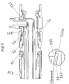
- FIG. 3 shows an advantageous embodiment of a hose connection part (13) according to the invention.
- the hose connection part (13) shown is a dispensing connection for a coaxial hose (not shown).
- the hose connection part (13) comprises a fluid channel (14) at one end (14a) of which a connecting device (15) is arranged, which is designed as an internal thread which engages with the corresponding external thread (2) of FIG Fig. 1 shown nut (1) can be connected liquid-tight.
- the hose connection part (13) has a structural element (16), which is designed to prevent the rotation protection (4) in Fig. 1 shown nut (1) from an open position to a closed position to transfer.
- the structural element (16) is arranged and dimensioned such that the twist protection (4) of the in Fig. 1 shown nut (1) at a certain point of the connection process between the hose connector (13) and the nut (1) by the structural element (16) of the hose connector (13) is transferred from the open position to the closed position, when the hose connector (13) the mother (1) is connected. This point is towards the end of the connection process, with the hose connector part (13) is designed such that the structural element (16) only then interacts with the nut (1) in order to transfer the twist protection (4) from the open position into the closed position, when the hose connection part (13) with the nut (1) is almost completely connected. This is in the FIGS. 4 and 5 graphically explained.
- FIG. 3 shows structural element (16) is circular and in the region of the connecting device (15) of the hose connecting part (13), wherein the structural element (16) adjacent to the end of the internal thread (15).
- the structural element (16) is designed to act on the clamping elements (5) of the Fig. 1 shown nut (1) by exerting a radial clamping force on the clamping elements (5), as in Fig. 5 shown.
- the structural element (16) causes a reduction in the inner diameter of the hose connecting part (13), such that on the clamping elements (5) of the in Fig. 1 shown nut (1) is applied a radial clamping force when the hose connecting part (13) with the nut (1) is connected as in Fig. 5 shown.
- the structural element (16) of the hose connection part (13) is designed to act directly on the clamping elements (5) of the nut (1).
- it is designed to hold the clamping elements (5) of the nut (1) by means of a radial clamping force in the clamping position, as from Fig. 5 seen.
- the hose connecting part (13) is designed so that the connecting device (15) also allows a connection with a counterpart that does not have anti-rotation protection according to the invention.
- the hose connection part (13) shown has in each case a connection (17a, 17b) at both ends (14a, 14b) of the fluid channel (14) and a third connection (17c) arranged between the ends (14a, 14b) of the fluid channel (14) , which is a gas outlet nipple. Also shown is a supply line (18) arranged within the fluid channel (14) to the third connection (17c).
- FIGS. 4 and 5 show the interaction of in Fig. 1 shown nut (1, 41, 51) with the in Fig. 2 shown hose nozzle (7, 47, 57) and the in Fig. 3 shown hose connector (13, 413, 513).
- the upper figure shows the parts in their entirety, while the lower figure shows an enlarged detail showing the interaction of the clamping elements (5, 45, 55) with the structural element (16, 416, 516).
- Fig. 4 shows the clamping elements (45) in the open position
- Fig. 5 shows the clamping elements (55) in the closed position.
- the holding element 511 a has metallic contact with the structural element 516.
- Fig. 4 As can be seen, the nut (41) arranged on the hose stub (47) almost completely joins the hose connection part (413), for example by means of manual assembly are connected while the clamping elements (45) remain in the open position. This allows an alignment of the tube (419). Then, as in Fig. 5 shown, the structural element (516) at a certain point towards the end of the connection process, namely, when the nut (51) with the hose connector (513) is almost completely connected, for example by means of key assembly, the clamping elements (55) in the clamping position and transfer hold in the clamping position for the duration of the connection by means of a radial clamping force.
- FIG. 6 shows the interaction of a conventional hose connection 619 without positioning option and anti-rotation with a hose connection part 613 according to the invention, comprising structural element 616, which is designed so that the connection device also allows a connection with a counterpart, which has no inventive anti-rotation.
- This allows a gradual retrofitting of existing hose connections by the hose connection is first retrofitted with a hose connector according to the invention before retrofitting with a nut according to the invention and a hose nozzle according to the invention.
- FIG. 7 shows an embodiment comprising a hose nozzle (757) according to the invention and arranged on the hose nozzle nut (751).
Landscapes
- Engineering & Computer Science (AREA)
- General Engineering & Computer Science (AREA)
- Mechanical Engineering (AREA)
- Joints That Cut Off Fluids, And Hose Joints (AREA)
- Loading And Unloading Of Fuel Tanks Or Ships (AREA)
- Joints With Pressure Members (AREA)
- Quick-Acting Or Multi-Walled Pipe Joints (AREA)
Description
- Die Erfindung betrifft eine Kombination gemäß dem Oberbegriff des Anspruchs 1, umfassend einen Schlauchstutzen für einen Fluidschlauch, eine Mutter zur Anordnung auf dem Schlauchstutzen sowie ein Schlauchanschlussteil für einen Fluidschlauch.
- Die Erfindung liegt auf dem Gebiet der Schlauchanschlüsse. Ein typisches Schlauchanschlussteil weist ein Innengewinde auf, das mit einem korrespondierenden Außengewinde eines Schlauchstutzens flüssigkeitsdicht verbunden werden kann. Aus allgemeiner Vorbenutzung sind beispielsweise Zapfsäulenanschlüsse bekannt, die ein feststehendes Innengewinde bzw. eine drehbare Metallmutter mit Innengewinde aufweisen. Diese können mit einem Schlauchstutzen mit Außengewinde flüssigkeitsdicht verbunden werden. Nachteilig an einem feststehenden Innengewinde ist, dass der Zapfschlauch, der in der Regel eine gewollte Krümmung aufweist, bei der Montage nicht ausgerichtet werden kann. Das Spiel einer drehbaren Mutter mit Innengwinde erlaubt hingegen zwar eine Ausrichtung des Zapfschlauchs, nicht jedoch dessen Fixierung in der gewünschten Ausrichtung.
- Die
US 5,285,744 offenbart eine Schlauchanordnung für die Kraftstoffleitung zu einer Zapfpistole, welche eine vollständige Rotation der Zapfpistole relativ zum angeschlossenen Schlauch erlaubt. Aus derUS 6,412832 B1 ist ein Fitting mit einer Mutter und einem Anschlussteil bekannt, zwischen denen ein speziell ausgebildetes Rohrende mit einer Nut eingeklemmt werden kann. DieUS 5 799 834 A offenbart ein Teleskopsteigrohr zur Verbindung einer elektrischen Tauchpumpe in einem Treibstoffspeichertank mit einem Verteilerkopf. DieEP 2 620 684 A1 betrifft eine Vorrichtung um Rohre und Zubehörteile zu verbinden, mit einem Haltekörper mit elastischen Radialelementen und einer mit dem Haltekörper zusammenwirkenden Mutter.GB 2 029 538 A US 2012/001425 A1 betrifft Hydraulikverbindungen mit einem männlichen Verbindungsteil und einem weiblichen Verbindungsteil, welche aufeinander abgestimmte Dichtflächen aufweisen.WO 89/10323 A1 US 5,746,454 A offenbart ein unterirdisches Rohrleitungssystem, das koaxiale Rohre mit einem primären Zuleitungsrohr und einem sekundären Einschlussrohr so miteinander verbindet, dass der Zwischenraum zwischen den beiden Rohren mit dem Zwischenraum in anderen Rohrsegmenten verbunden werden kann. DieUS 2011/0067779 A1 betrifft Dampfrückgewinnungsventile. - Vor diesem Hintergrund ist es die Aufgabe der Erfindung, Mittel zum Anschließen eines Schlauchs bereitzustellen, die ein einfaches Ausrichten und Fixieren des Schlauchs bei der Montage ermöglichen.
- Gelöst wird diese Aufgabe durch eine Kombination der eingangs genannten Art mit den Merkmalen des Anspruchs 1, mit einer Mutter, einem Schlauchstutzen und einem Schlauchanschlussteil, die jeweils so aufeinander abgestimmt sind, dass sie zur Lösung des Problems zusammenwirken.
- Zunächst sei die erfindungsgemäße Mutter erläutert.
- Eine erfindungsgemäße Mutter zur Anordnung auf einem Schlauchstutzen weist eine Verbindungsvorrichtung auf, welche mit einem Schlauchanschlussteil flüssigkeitsdicht verbindbar ist. Hierbei kann es sich um jede geeignete, im Stand der Technik bekannte Verbindungsvorrichtung handeln. Im Rahmen der Erfindung ist es bevorzugt, wenn die Verbindungsvorrichtung ein Außengewinde umfasst, welches mit einem korrespondierenden Innengewinde des Schlauchanschlussteils flüssigkeitsdicht verbindbar ist.
- Eine erfindungsgemäße Mutter weist zudem eine Aufnahme für den Schlauchstutzen auf, mit einem ersten Ende und einem zweiten Ende, wobei die Aufnahme dazu ausgebildet ist, den Schlauchstutzen in Umfangsrichtung formschlüssig zu umfassen, derart, dass die Mutter und der Schlauchstutzen in Umfangsrichtung gegeneinander drehbar sind. Die Begriffe Umfangsrichtung, Axialrichtung und Radialrichtung beziehen sich im Rahmen der Erfindung auf die Geometrie der Mutter, wobei die Axialrichtung die Richtung parallel zur Innenumfangsfläche der Aufnahme für den Schlauchstutzen und quer zur Umfangsrichtung bezeichnet.
- Die erfindungsgemäße Lösung sieht vor, dass die Mutter einen Verdrehschutz aufweist, der so ausgebildet ist, dass der durch ein Strukturelement des Schlauchanschlussteils von einer Offenstellung, in der die Mutter und der Schlauchstutzen in Umfangsrichtung gegeneinander drehbar sind, wenn die Mutter auf dem Schlauchstutzen angeordnet ist, überführbar ist in eine Geschlossenstellung, in der ein Drehen der Mutter in Umfangsrichtung relativ zum Schlauchstutzen verhindert wird, wenn die Mutter auf dem Schlauchstutzen angeordnet ist.
- Im Rahmen der Erfindung sind die Begriffe Offenstellung und Geschlossenstellung nicht auf diskrete Zustände beschränkt. Im Rahmen der Erfindung kann der Übergang von der Offenstellung in die Geschlossenstellung fließend sein. Die Unterscheidung zwischen Offenstellung und Geschlossenstellung kann von einem bestimmten Drehmoment abhängen, das erforderlich ist, um ein Drehen der Mutter in Umfangsrichtung relativ zum Schlauchstutzen zu bewirken. Anders ausgedrückt, umfasst im Rahmen der Erfindung der Begriff Geschlossenstellung auch solche Ausführungsformen der Erfindung, bei denen ein Drehen der Mutter in Umfangsrichtung relativ zum Schlauchstutzen unterhalb eines bestimmten Drehmomentschwellenwerts verhindert wird, der vorzugsweise so gewählt ist, dass im normalen Gebrauch der erfindungsgemäßen Mutter, bzw. des erfindungsgemäßen Schlauchstutzens, ein Drehen der Mutter in Umfangsrichtung relativ zum Schlauchstutzen verhindert wird. Im Rahmen der Erfindung ist der Drehmomentschwellenwert bevorzugt größer 10 Nm, weiter vorzugsweise größer 20 Nm, weiter vorzugsweise größer 30 Nm, besonders bevorzugt größer 40 Nm. Weitere im Rahmen der Erfindung bevorzugte Drehmomentschwellenwerte liegen im Bereich von 10 Nm bis 50 Nm, weiter vorzugsweise im Bereich von 10 Nm bis 40 Nm, weiter vorzugsweise im Bereich von 20 Nm bis 30 Nm, besonders bevorzugt im Bereich von 40 Nm bis 50 Nm.
- Die Erfindung hat erkannt, dass ein entsprechend ausgebildeter Verdrehschutz eine einfache Ausrichtung und Fixieren des Schlauchs bei der Montage erlaubt. So kann ein am Schlauchstutzen befestigter Schlauch in der Offenstellung des Verdrehschutzes dadurch ausgerichtet werden, dass der Schlauchstutzen relativ zur Mutter in Umfangsrichtung gedreht wird, bis die gewünschte Ausrichtung erreicht ist. Der Verdrehschutz kann sodann durch Zusammenwirken der Mutter mit dem Schlauchanschlussteil von der Offenstellung in die Geschlossenstellung überführt werden, um den Schlauch in der gewünschten Ausrichtung zu fixieren.
- Die Mutter ist wie oben beschrieben auf ein Schlauchanschlussteil abgestimmt. Bei dem Schlauchanschlussteil kann es sich um ein Schlauchanschlussteil für einen Fluidschlauch, vorzugsweise für einen Flüssigkeitsschlauch, besonders bevorzugt für einen Kraftstoffzapfschlauch handeln, umfassend einen Fluidkanal an dessen einem Ende eine Verbindungsvorrichtung angeordnet ist, welche eine flüssigkeitsdichte Verbindung mit der Mutter erlaubt, wobei die Verbindungsvorrichtung jede im Stand der Technik bekannte, geeignete Verbindungsvorrichtung sein kann, wobei die Verbindungsvorrichtung bevorzugt ein Innengewinde umfasst, das mit einem korrespondierenden Außengewinde der Mutter verbunden werden kann, wobei das Schlauchanschlussteil ein Strukturelement umfasst, das dazu ausgebildet ist, den Verdrehschutz der Mutter von einer Offenstellung in eine Geschlossenstellung zu überführen. Die Mutter kann insbesondere auf ein Schlauchanschlussteil der unten beschriebenen Art abgestimmt sein. Auf die unten stehenden Ausführungen zum erfindungsgemäßen Schlauchanschlussteil wird im Kontext der Mutter zur Vermeidung von Wiederholungen ausdrücklich Bezug genommen.
- Die Mutter ist wie oben beschrieben auf einen Schlauchstutzen abgestimmt. Bei dem Schlauchstutzen kann es sich um einen Schlauchstutzen für einen Fluidschlauch, vorzugsweise für einen Flüssigkeitsschlauch, besonders bevorzugt für einen Kraftstoffzapfschlauch handeln, mit einem Rohransatz zum Befestigen des Fluidschlauchs, wobei die Außenseite des Schlauchstutzens eine Auflagefläche für die Mutter aufweist, wobei die Abmessungen des Schlauchstutzens so auf die Mutter abgestimmt sind, dass der Schlauchstutzen von der Mutter formschlüssig umfasst werden kann, derart, dass der Schlauchstutzen und die Mutter in Umfangsrichtung gegeneinander drehbar sind. Die Mutter kann insbesondere auf einen Schlauchstutzen der unten beschriebenen Art abgestimmt sein. Auf die unten stehenden Ausführungen zum Schlauchstutzen wird im Kontext der Mutter zur Vermeidung von Wiederholungen ausdrücklich Bezug genommen.
- Im Rahmen der Erfindung ist die Mutter bevorzugt so ausgebildet, dass der Verdrehschutz an einem bestimmten Punkt des Verbindungsvorgangs zwischen der Mutter und dem Schlauchanschlussteil durch das Strukturelement des Schlauchanschlussteils von der Offenstellung in die Geschlossenstellung überführt wird, wenn die Mutter mit dem Schlauchanschlussteil verbunden wird. Dies hat den Vorteil, dass die Fixierung des Schlauchs an einem bestimmten Punkt des Verbindungsvorgangs erfolgt. Vorzugsweise liegt dieser Punkt gegen Ende des Verbindungsvorgangs. Besonders vorteilhaft ist es, wenn die Mutter so ausgebildet ist, dass der Verdrehschutz erst dann mit dem Strukturelement des Schlauchanschlussteils zusammenwirkt, um den Verdrehschutz von der Offenstellung in die Geschlossenstellung zu überführen, wenn die Mutter mit dem Schlauchanschlussteil beinahe vollständig verbunden ist. Beinahe vollständig verbunden bedeutet im Rahmen der Erfindung, dass nur noch ein geringer Aufwand nötig ist, um den Verbindungsvorgang zwischen der Mutter und dem Schlauchanschlussteil abzuschließen. Dies hat den Vorteil, dass der Schlauch erst gegen Ende des Verbindungsvorgangs ausgerichtet werden muss und mit geringem Aufwand in der gewünschten Ausrichtung fixiert werden kann. Am Beispiel einer Schraubverbindung erläutert bedeutet dies, dass der Monteur das Schlauchanschlussteil mit der auf dem Schlauchstutzen angeordneten Mutter, beispielsweise mittels Handmontage, weitgehend verschrauben kann, bevor der Schlauch gegen Ende des Verschraubungsvorgangs ausgerichtet wird und sodann, zum Beispiel mittels Schlüsselmontage, durch ein Zusammenwirken der Mutter mit dem Schlauchanschlussteil fixiert wird.
- Die Verbindungsvorrichtung der Mutter ist bevorzugt an der Außenseite der Mutter angeordnet. Im Rahmen der Erfindung bezeichnet die Außenseite der Mutter diejenige Seite der Mutter, welche dem Schlauchstutzen abgewandt ist, wenn die Mutter auf dem Schlauchstutzen angeordnet ist. Entsprechend bezeichnet die Innenseite der Mutter im Rahmen der Erfindung diejenige Seite der Mutter, welche dem Schlauchstutzen zugewandt ist, wenn die Mutter auf dem Schlauchstutzen angeordnet ist.
- Vorzugsweise ist der Verdrehschutz an der Innenseite der Mutter angeordnet. Dies erleichtert das Zusammenwirken des Verdrehschutzes mit dem Schlauchstutzen. Es ist vorteilhaft, wenn der Verdrehschutz im Bereich der Verbindungsvorrichtung angeordnet ist. Dies erleichtert das Zusammenwirken der Mutter mit dem Schlauchanschlussteil, um den Verdrehschutz von einer Offenstellung in eine Geschlossenstellung zu überführen. Vorzugsweise sind sowohl der Verdrehschutz als auch die Verbindungsvorrichtung der Mutter im Bereich des ersten Endes der Aufnahme angeordnet. Besonders bevorzugt ist der Verdrehschutz an der Innenseite der Mutter im Bereich des ersten Endes der Aufnahme angeordnet, wobei der Verdrehschutz in die Aufnahme hineinragt, und die Verbindungsvorrichtung ist an der Außenseite der Mutter im Bereich des ersten Endes der Aufnahme angeordnet, wobei sich die Verbindungsvorrichtung außerhalb der Aufnahme befindet.
- Im Rahmen der Erfindung kann das Zusammenwirken der Mutter mit dem Schlauchanschlussteil die Ausübung einer Kraft auf den Verdrehschutz durch das Strukturelement des Schlauchanschlussteils umfassen, insbesondere die Ausübung einer radialen Kraft.
- Eine vorteilhafte Ausführungsform der Erfindung sieht vor, dass der Verdrehschutz mindestens ein, bevorzugt an der Innenseite der Mutter angeordnetes, Klemmelement umfasst, das von einer Offenstellung, die eine Drehbewegung der Mutter in Umfangsrichtung relativ zum Schlauchstutzen erlaubt, wenn die Mutter auf dem Schlauchstutzen angeordnet ist, in eine Klemmstellung überführbar ist, in der das Klemmelement, zur Verhinderung einer Drehbewegung der Mutter in Umfangsrichtung relativ zum Schlauchstutzen, gegen den Schlauchstutzen gedrückt wird, wenn die Mutter auf dem Schlauchstutzen angeordnet ist.
- Im Rahmen der Erfindung sind die Begriffe Offenstellung und Klemmstellung nicht auf diskrete Zustände beschränkt. Im Rahmen der Erfindung kann der Übergang von der Offenstellung in die Klemmstellung fließend sein. Die Unterscheidung zwischen Offenstellung und Klemmstellung kann von einem bestimmten Drehmoment abhängen, das erforderlich ist, um ein Drehen der Mutter in Umfangsrichtung relativ zum Schlauchstutzen zu bewirken. Anders ausgedrückt, umfasst im Rahmen der Erfindung der Begriff Klemmstellung auch solche Ausführungsformen der Erfindung, bei denen ein Drehen der Mutter in Umfangsrichtung relativ zum Schlauchstutzen unterhalb eines bestimmten Drehmomentschwellenwerts verhindert wird, der vorzugsweise so gewählt ist, dass im normalen Gebrauch der erfindungsgemäßen Mutter, bzw. des erfindungsgemäßen Schlauchstutzens, ein Drehen der Mutter in Umfangsrichtung relativ zum Schlauchstutzen verhindert wird. Im Rahmen der Erfindung ist der Drehmomentschwellenwert bevorzugt größer 10 Nm, weiter vorzugsweise größer 20 Nm, weiter vorzugsweise größer 30 Nm, besonders bevorzugt größer 40 Nm. Weitere im Rahmen der Erfindung bevorzugte Drehmomentschwellenwerte liegen im Bereich von 10 Nm bis 50 Nm, weiter vorzugsweise im Bereich von 10 Nm bis 40 Nm, weiter vorzugsweise im Bereich von 20 Nm bis 30 Nm, besonders bevorzugt im Bereich von 40 Nm bis 50 Nm.
- Bevorzugt ist das mindestens eine Klemmelement so dimensioniert und angeordnet, dass das Strukturelement des Schlauchanschlussteils direkt auf das Klemmelement wirken kann. Dies ermöglicht eine vergleichsweise einfache bauliche Realisierung.
- Vorteilhafterweise ist die Mutter so ausgebildet, dass das mindestens eine Klemmelement an einem bestimmten Punkt des Verbindungsvorgangs zwischen der Mutter und dem Schlauchanschlussteil durch ein Zusammenwirken mit dem Strukturelement des Schlauchanschlussteils von der Offenstellung in die Klemmstellung überführt wird, wenn die Mutter mit dem Schlauchanschlussteil verbunden wird. Dies hat den Vorteil, dass die Fixierung des Schlauchs an einem bestimmten Punkt des Verbindungsvorgangs erfolgt. Vorzugsweise liegt dieser Punkt gegen Ende des Verbindungsvorgangs. Das mindestens eine Klemmelement ist vorzugsweise so angeordnet und dimensioniert, dass es erst dann mit dem Strukturelement des Schlauchanschlussteils zusammenwirkt, um das Klemmelement von der Klemmstellung in die Offenstellung zu überführen, wenn die Mutter mit dem Schlauchanschlussteil beinahe vollständig verbunden ist. Letzteres hat den Vorteil, dass der Schlauch erst gegen Ende des Verbindungsvorgangs ausgerichtet werden muss und mit geringem Aufwand in der gewünschten Ausrichtung fixiert werden kann.
- Das mindestens eine Klemmelement ist vorzugsweise dazu ausgelegt, mittels einer Klemmkraft, bevorzugt einer radialen Klemmkraft, in der Klemmstellung gehalten zu werden. In einer besonders bevorzugten Ausführungsform der Erfindung, ist das mindestens eine Klemmelement dazu ausgelegt, durch direkte Einwirkung des Strukturelements mittels einer radialen Klemmkraft in der Klemmstellung gehalten zu werden.
- Es kann vorgesehen sein, dass der Verdrehschutz mindestens zwei Klemmelemente umfasst. Vorteilhafterweise sind die Klemmelemente in Umfangsrichtung voneinander beabstandet. Die Abstände zwischen den Klemmelementen können jeweils gleich groß sein. Vorzugsweise umfasst der Verdrehschutz 2 bis 12, weiter vorzugsweise 4 bis 8, besonders bevorzugt 6 Klemmelemente, welche jeweils in Umfangsrichtung voneinander beabstandet sein können.
- Vorteilhafterweise umfasst die Verbindungsvorrichtung ein Außengewinde, welches mit einem korrespondierenden Innengewinde des Schlauchanschlussteils flüssigkeitsdicht verbindbar ist, wobei das Klemmelement oder die Klemmelemente in Axialrichtung über das Außengewinde hinausragen.
- Es kann vorgesehen sein, dass die Verbindungsvorrichtung an der Außenseite der Mutter im Bereich des ersten Endes der Aufnahme angeordnet ist und/oder das Klemmelement oder die Klemmelemente an der Innenseite der Mutter im Bereich des ersten Endes der Aufnahme angeordnet sind.
- Vorzugsweise sind das Klemmelement oder die Klemmelemente an der Innenseite der Mutter angeordnet. Dies erleichtert das Zusammenwirken mit dem Schlauchstutzen. Es ist vorteilhaft, wenn das Klemmelement oder die Klemmelemente, im Bereich der Verbindungsvorrichtung angeordnet sind. Dies erleichtert das Zusammenwirken der Klemmelemente mit dem Strukturelement des Schlauchanschlussteils in Abhängigkeit vom Verbindungsvorgang zwischen der Mutter und dem Schlauchanschlussteil. Vorzugsweise sind sowohl das Klemmelement oder die Klemmelemente als auch die Verbindungsvorrichtung der Mutter im Bereich des ersten Endes der Aufnahme angeordnet. Besonders bevorzugt ist das Klemmelement oder die Klemmelemente an der Innenseite der Mutter im Bereich des ersten Endes der Aufnahme angeordnet, wobei das Klemmelement oder die Klemmelemente in die Aufnahme hineinragen, und die Verbindungsvorrichtung ist an der Außenseite der Mutter im Bereich des ersten Endes der Aufnahme angeordnet, wobei sich die Verbindungsvorrichtung außerhalb der Aufnahme befindet.
- Die Mutter kann aus Kunststoff, vorzugsweise aus einem elektrisch leitfähigen Kunststoff, besonders bevorzugt aus einem elektrisch leitfähigen Kunststoff mit einem elektrischen Widerstand gemäß EN 13617-2 kleiner 100 000 Ohm, vorzugsweise mit einem elektrischen Widerstand gemäß EN 13617-2 zwischen 200 und 1000 Ohm bestehen. Der Kunststoff ist vorzugsweise ausgewählt aus der Gruppe bestehend aus Polyamiden (PA) und Polyetheretherketonen (PEEK).
- Die Mutter ist bevorzugt dazu ausgebildet, dass die Verbindung zwischen der Mutter und dem Schlauchanschlussteil einer Zugkraft von mindestens 2000 N über 2 min, vorzugsweise mindestens 2000 N über 5 min standhält. Die Messung erfolgt gemäß EM 13483 Anhang K, wobei die Kraft aufgebracht wird, indem die Klemmen der Prüfvorrichtung mit einer Geschwindigkeit von (75±5) mm/min auseinandergezogen werden.
- Vorteilhafterweise weist die Mutter Verstärkungselemente auf, wobei die Verstärkungselemente vorzugsweise in Umfangsrichtung voneinander beabstandet sind und/oder Vorzugsweise an der Innenseite der Mutter, bevorzugt im Bereich des ersten Endes der Aufnahme, angeordnet sind und/oder vorzugsweise im Beeich der Verbindungsvorrichtung angeordnet sind. Die Anordnung der Verstärkungselemente im Bereich der Verbindungsvorrichtung dient der Erhöhung der Zugfestigkeit der Verbindung zwischen der Mutter und dem Schlauchanschlussteil.
- Die Aufnahme für den Schlauchstutzen kann sich vorteilhafterweise über die gesamte axiale Ausdehnung der Mutter erstrecken.
- Vorteilhafterweise ist die Mutter dazu ausgelegt mit einem Schlauchanschlussteil für einen Kraftstoff- und/oder Gasschlauch, vorzugsweise mit einem Zapfsäulenanschluss, besonders bevorzugt mit einem Zapfsäulenanschluss für einen Koaxialschlauch verbunden zu werden.
- Es ist vorteilhaft, wenn die Verbindungsvorrichtung der Mutter so ausgebildet ist, dass sie auch eine Verbindung mit einem Schlauchanschlussteil erlaubt, das kein erfindungsgemäßes Strukturelement aufweist. Eine solche Verbindung erlaubt zwar nur die Ausrichtung des Schlauchs und nicht seine Fixierung. Sie ermöglicht aber ein schrittweises Nachrüsten von bestehenden Schlauchanschlüssen, indem der Schlauchanschluss zuerst mit einer erfindungsgemäßen Mutter und einem erfindungsgemäßen Schlauchstutzen nachgerüstet wird, bevor eine Nachrüstung mit einem erfindungsgemäßen Schlauchanschlussteil erfolgt.
- Die Mutter dient zur Anordnung auf einem Schlauchstutzen und kann zu dieser Anordnung bestimmt sein. Die Erfindung ist nicht auf eine bestimmte Art der Anordnung beschränkt. Beispielsweise kann die Mutter auf einen Schlauchstutzen aufsteckbar sein. In diesem Fall ist es vorteilhaft, wenn die Mutter mindestens ein Rastelement aufweist, das mit mindestens einem Halteelement des Schlauchstutzens zusammenwirken kann, um die Mutter auf dem Schlauchstutzen in Axialrichtung zu fixieren und/oder wenn mindestens ein Klemmelement der Mutter als Rastelement ausgebildet ist, derart, dass es mit mindestens einem Halteelement des Schlauchstutzenszusammenwirken kann, um die Mutter auf dem Schlauchstutzen in Axialrichtung zu fixieren.
- Die Mutter kann als Mehrkantmutter, vorzugsweise als Dreikant-, Vierkant-, Sechskant-, Achtkant- oder Zwölfkantmutter, besonders bevorzugt als Sechskantmutter, ausgebildet sein. Vorteilhafterweise ist die Mehrkantstruktur an der Außenseite der Mutter im Bereich des zweiten Endes der Aufnahme angeordnet.
- Gegenstand der Erfindung ist ferner ein Schlauchstutzen. Dieser sei nachstehend erläutert.
- Schlauchstutzen sind dem Fachmann bekannt. Sie weisen einen Durchgang für das Fluid und in der Regel einen Rohransatz zum Befestigen des Schlauchs auf.
- Bei dem erfindungsgemäßen Schlauchstutzen handelt es sich um einen Schlauchstutzen für einen Fluidschlauch, vorzugsweise für einen Flüssigkeitsschlauch, besonders bevorzugt für einen Kraftstoffzapfschlauch, mit einem Rohransatz zum Befestigen des Fluidschlauchs, wobei die Außenseite des Schlauchstutzens eine Auflagefläche für die Mutter aufweist, wobei die Abmessungen des Schlauchstutzens so auf die Mutter abgestimmt sind, dass der Schlauchstutzen von der Mutter formschlüssig umfasst werden kann, derart, dass der Schlauchstutzen und die Mutter in Umfangsrichtung gegeneinander drehbar sind.
- Der Schlauchstutzen ist wie oben beschrieben auf eine Mutter abgestimmt. Dabei kann es sich um eine Mutter zur Anordnung auf dem Schlauchstutzen handeln, die eine Verbindungsvorrichtung umfasst, welche mit einem Schlauchanschlussteil flüssigkeitsdicht verbindbar ist, sowie eine Aufnahme für den Schlauchstutzen, mit einem ersten Ende und einem zweiten Ende, wobei die Aufnahme dazu ausgebildet ist, den Schlauchstutzen in Umfangsrichtung formschlüssig zu umfassen, derart, dass die Mutter und der Schlauchstutzen in Umfangsrichtung gegeneinander drehbar sind, wobei die Mutter einen Verdrehschutz aufweist, der so ausgebildet ist, dass er durch ein Strukturelement des Schlauchanschlussteils von einer Offenstellung, in der die Mutter auf dem Schlauchstutzen angeordnet ist, überführbar ist in eine Geschlossenstellung, in der ein Drehen der Mutter in Umfangsrichtung relativ zum Schlauchstutzen verhindert wird, wenn die Mutter auf dem Schlauchstutzen angeordnet ist. Der Schlauchstutzen kann insbesondere auf eine Mutter der weiter oben beschriebenen Art abgestimmt sein. Auf die oben stehenden Ausführungen zur Mutter wird im Kontext des Schlauchstutzens zur Vermeidung von Wiederholungen ausdrücklich Bezug genommen. Wie die Begriffe Offenstellung und Geschlossenstellung im Rahmen der Erfindung zu verstehen sind, wurde bereits im Kontext der erfindungsgemäßen Mutter erläutert. Auf diese Ausführungen wird im Kontext des Schlauchstutzens Bezug genommen.
- Vorteilhafterweise weist der Schlauchstutzen eine Haltevorrichtung auf, die dazu ausgebildet ist, eine Axialbewegung der Mutter relativ zum Schlauchstutzen zu verhindern, wobei die Haltevorrichtung vorzugsweise zwei Halteelemente umfasst, die zwischen sich die Auflagefläche für die Mutter definieren. Vorzugsweise ist mindestens eines der Halteelemente als Flansch ausgebildet. Besonders bevorzugt sind beide Halteelemente als Flansche ausgebildet. Der oder die Flansche können durchgehend in Umfangsrichtung verlaufen. Es ist aber auch möglich, dass der oder die Flansche in Umfangsrichtung eine oder mehrere Unterbrechungen aufweisen.
- Bei einer vorteilhaften Ausführungsform weist der Schlauchstutzen an seiner Außenseite wenigstens einen Abschnitt auf, der dazu vorgesehen ist, dem mindestens einen Klemmelement der Mutter zumindest teilweise als Widerlager zu dienen. Dieser Abschnitt ist vorzugsweise im Bereich der Auflagefläche angeordnet.
- Vorzugsweise ist der Schlauchstutzen dazu ausgebildet, mit seiner Außenseite das Schlauchanschlussteil zu berühren, um elektrischen Durchgang zu erzeugen. Besonders bevorzugt ist der Schlauchstutzen dazu ausgebildet, mit einem seiner Halteelemente ein Schlauchanschlussteil zu berühren, um elektrischen Durchgang zu erzeugen.
- Vorzugsweise ist der Schlauchstutzen für die Verwendung mit einem Kraftstoffschlauch, vorzugsweise einem Koaxialschlauch für Kraftstoffe, ausgelegt.
- Gegenstand der Erfindung ist ferner ein Schlauchanschlussteil. Dieses sei nachstehend erläutert.
- Bei dem erfindungsgemäßen Schlauchanschlussteil handelt es sich um ein Schlauchanschlussteil für einen Fluidschlauch, vorzugsweise für einen Flüssigkeitsschlauch, besonders bevorzugt für einen Kraftstoffzapfschlauch, wobei das Schlauchanschlussteil einen Fluidkanal umfasst an dessen einem Ende eine Verbindungsvorrichtung angeordnet ist, die eine flüssigkeitsdichte Verbindung mit einer oben beschriebenen Mutter erlaubt, wobei das Schlauchanschlussteil ein Strukturelement aufweist, das dazu ausgebildet ist, den Verdrehschutz der Mutter von einer Offenstellung in eine Geschlossenstellung zu überführen. Wie die Begriffe Offenstellung und Geschlossenstellung im Rahmen der Erfindung zu verstehen sind, wurde bereits im Kontext der erfindungsgemäßen Mutter erläutert. Auf diese Ausführungen wird im Kontext des Schlauchanschlussteils Bezug genommen.
- Der Begriff Fluidkanal bezeichnet im Rahmen der Erfindung einen Kanal, der für die Durchleitung eines Fluids ausgelegt ist. Der Fluidkanal kann vorzugsweise eine im Wesentlichen zylindrische Form aufweisen.
- Das Schlauchanschlussteil ist wie oben beschrieben auf eine Mutter abgestimmt. Dabei kann es sich um eine Mutter zur Anordnung auf einem Schlauchstutzen handeln, die eine Verbindungsvorrichtung umfasst, welche mit dem Schlauchanschlussteil flüssigkeitsdicht verbindbar ist, sowie eine Aufnahme für den Schlauchstutzen, mit einem ersten Ende und einem zweiten Ende, wobei die Aufnahme dazu ausgebildet ist, den Schlauchstutzen in Umfangsrichtung formschlüssig zu umfassen, derart, dass die Mutter und der Schlauchstutzen in Umfangsrichtung gegeneinander drehbar sind, wobei die Mutter einen Verdrehschutz aufweist, der so ausgebildet ist, dass er durch ein Strukturelement des Schlauchanschlussteils von einer Offenstellung, in der die Mutter auf dem Schlauchstutzen angeordnet ist, überführbar ist in eine Geschlossenstellung, in der ein Drehen der Mutter in Umfangsrichtung relativ zum Schlauchstutzen verhindert wird, wenn die Mutter auf dem Schlauchstutzen angeordnet ist. Das Schlauchanschlussteil kann insbesondere auf eine Mutter der weiter oben beschriebenen Art abgestimmt sein. Auf die oben stehenden Ausführungen zur Mutter wird im Kontext des Schlauchstutzens zur Vermeidung von Wiederholungen ausdrücklich Bezug genommen.
- Vorzugsweise umfasst die Verbindungsvorrichtung des Schlauchanschlussteils ein Innengewinde, das mit einem korrespondierenden Außengewinde der Mutter verbunden werden kann.
- Vorteilhafterweise ist das Strukturelement so angeordnet und dimensioniert, dass der Verdrehschutz der Mutter an einem bestimmten Punkt des Verbindungsvorgangs zwischen dem Schlauchanschlussteil und der Mutter durch das Strukturelement des Schlauchanschlussteils von der Offenstellung in die Geschlossenstellung überführt wird, wenn das Schlauchanschlussteil mit der Mutter verbunden wird. Dies hat den Vorteil, dass die Fixierung des Schlauchs an einem bestimmten Punkt des Verbindungsvorgangs erfolgt. Vorzugsweise liegt dieser Punkt gegen Ende des Verbindungsvorgangs. Das Schlauchanschlussteil ist vorzugsweise so ausgebildet, dass das Strukturelement erst dann mit der Mutter zusammenwirkt, um den Verdrehschutz von der Offenstellung in die Geschlossenstellung zu überführen, wenn das Schlauchanschlussteil mit der Mutter beinahe vollständig verbunden ist. Letzteres hat den Vorteil, dass der Schlauch erst gegen Ende des Verbindungsvorgangs ausgerichtet werden muss und mit geringem Aufwand in der gewünschten Ausrichtung fixiert werden kann.
- Bei einer vorteilhaften Ausführungsform weist das Strukturelement mindestens ein Merkmal, vorzugsweise beide Merkmale, ausgewählt aus der nachfolgenden Merkmalsgruppe auf:
- das Strukturelement ist ringförmig, vorzugsweise kreisförmig,
- das Strukturelement ist im Bereich der Verbindungsvorrichtung des Schlauchanschlussteils angeordnet, wobei das Strukturelement vorzugsweise an den Abschluss des Innengewindes angrenzt;
- Das Strukturelement kann vorzugsweise dazu ausgebildet sein, mit einer der oben beschriebenen Ausführungsformen der Mutter zusammenzuwirken, die mindestens ein Klemmelement umfasst, wobei das Strukturelement mindestens ein Merkmal, vorzugsweise mindestens zwei Merkmale, besonders bevorzugt alle drei Merkmale ausgewählt aus der nachfolgenden Merkmalsgruppe aufweist:
- das Strukturelement ist dazu ausgebildet, auf mindestens ein Klemmelement der Mutter zu wirken,
- das Strukturelement ist dazu ausgebildet, eine Klemmkraft, vorzugsweise eine radiale Klemmkraft, auf das mindestens eine Klemmelement auszuüben,
- das Strukturelement bewirkt eine Verringerung des Innendurchmessers des Schlauchanschlussteils, derart, dass auf das mindestens eine Klemmelement der Mutter eine Klemmkraft, vorzugsweise eine radiale Klemmkraft, ausgeübt wird, wenn das Schlauchanschlussteil mit der Mutter verbunden ist, wobei das Strukturelement vorzugsweise dazu ausgebildet ist direkten metallischen Kontakt mit einem Schlauchstutzen herzustellen.
- Das oben genannte Merkmal, dass das Strukturelement dazu ausgebildet ist, direkten metallischen Kontakt mit einem Schlauchstutzen herzustellen, ist insbesondere für solche Länder bevorzugt, in welchen elektrischer Durchgang gefordert wird. Bei dem Schlauchstutzen kann es sich um einen Schlauchstutzen für einen Fluidschlauch, vorzugsweise für einen Flüssigkeitsschlauch, besonders bevorzugt für einen Kraftstoffzapfschlauch handeln, mit einem Rohransatz zum Befestigen des Fluidschlauchs, wobei die Außenseite des Schlauchstutzens eine Auflagefläche für eine Mutter, vorzugsweise für die weiter oben beschriebene Mutter, aufweist, wobei die Abmessungen des Schlauchstutzens so auf die Mutter abgestimmt sind, dass der Schlauchstutzen von der Mutter formschlüssig umfasst werden kann, derart, dass der Schlauchstutzen und die Mutter in Umfangsrichtung gegeneinander drehbar sind. Insbesondere kann es sich bei dem Schlauchstutzen um einen Schlauchstutzen der weiter oben beschriebenen Art handeln. Auf die oben stehenden Ausführungen zum Schlauchstutzen wird im Kontext des Schlauchanschlussteils zur Vermeidung von Wiederholungen ausdrücklich Bezug genommen.
- In einer bevorzugten Ausführungsform der Erfindung, ist das Strukturelement des Schlauchanschlussteils dazu ausgelegt, direkt auf das mindestens eine Klemmelement der Mutter einzuwirken. In einer besonders bevorzugten Ausführungsform ist das Strukturelement dazu ausgelegt, das mindestens eine Klemmelement der Mutter mittels einer radialen Klemmkraft in der Klemmstellung zu halten. Wie der Begriff Klemmstellung im Rahmen der Erfindung zu verstehen ist, wurde bereits im Kontext der erfindungsgemäßen Mutter erläutert. Auf diese Ausführungen wird im Kontext des Schlauchanschlussteils Bezug genommen.
- Vorzugsweise handelt es sich bei dem Schlauchanschlussteil um ein Schlauchanschlussteil für einen Kraftstoff- und/oder Gasschlauch, weiter vorzugsweise um einen Zapfsäulenanschluss, besonders bevorzugt um einen Zapfsäulenanschluss für einen Koaxialschlauch.
- Es ist vorteilhaft, wenn das Schlauchanschlussteil so ausgebildet ist, dass die Verbindungsvorrichtung auch eine Verbindung mit einem Gegenstück erlaubt, das keinen erfindungsgemäßen Verdrehschutz aufweist. Dies ermöglicht ein schrittweises Nachrüsten von bestehenden Schlauchanschlüssen, indem der Schlauchanschluss zuerst mit einem erfindungsgemäßen Schlauchanschlussteil nachgerüstet wird, bevor eine Nachrüstung mit einer erfindungsgemäßen Mutter und einem erfindungsgemäßen Schlauchstutzen erfolgt.
- Vorteilhafterweise weist das Schlauchanschlussteil mehrere Anschlüsse auf, von denen vorzugsweise mindestens einer eine drehbar gelagerte Mutter umfasst, wobei die drehbar gelagerte Mutter vorzugsweise ein Innengewinde aufweist. Bevorzugt weist das Schlauchanschlussteil mindestens zwei, besonders bevorzugt mindestens drei Anschlüsse auf, wobei einer der Anschlüsse als ein Gasausgangsnippel ausgebildet sein kann. Bei einer bevorzugten Ausführungsform weist das Schlauchanschlussteil jeweils einen Anschluss an beiden Enden des Fluidkanals und optional einen zwischen den Enden des Fluidkanals angeordneten dritten Anschluss auf, wobei es sich bei dem optionalen dritten Anschluss um einen Gasauslassnippel handeln kann. Das Schlauchanschlussteil kann eine in dem Fluidkanal angeordnete Zuleitung für den dritten Kanal umfassen.
- Gegenstand der Erfindung ist zudem ein Kit für einen Schlauchanschluss umfassend eine oben beschriebene Mutter, einen oben beschriebenen Schlauchstutzen und ein oben beschriebenenes Schlauchanschlussteil.
- In einer bevorzugten Kombination, ist die Mutter auf dem Schlauchstutzen angeordnet. Bei anderen vorteilhaften Ausführungsformen ist die Mutter nicht auf dem Schlauchstutzen angeordnet.
- Eine für den erfindungsgemäßen Kit geeignete Mutter, sowie ein für den Kit geeignetes Schlauchanschlussteil und ein geeigneter Schlauchstutzen wurden bereits oben beschrieben. Auf diese Ausführungen wird im Kontext des erfindungsgemäßen Kits zur Vermeidung von Wiederholungen Bezug genommen. Im Rahmen des erfindungsgemäßen Kits sei hiermit jegliche Kombination von drei Komponenten aus der Gruppe bestehend aus einer oben beschriebenen Mutter, einem oben beschriebenen Schlauchstutzen und einem oben beschriebenen Schlauchanschlussteil explizit offenbart.
- Die Erfindung sieht ferner die Verwendung einer oben beschriebenen Mutter mit einem oben beschriebenen Schlauchstutzen und einem oben beschriebenen Schlauchanschlussteil vor. Im Rahmen der erfindungsgemäßen Verwendung sei hiermit jegliche Kombination einer oben beschriebenen Mutter mit einem oben beschriebenen Schlauchstutzen und einem oben beschriebenen Schlauchanschlussteil explizit offenbart. Zur Vermeidung von Wiederholungen wird im Kontext der erfindungsgemäßen Verwendung ausdrücklich auf die obigen Ausführungen zur Mutter, zum Schlauchanschlussteil und zum Schlauchstutzen verwiesen.
- Die Erfindung sieht ferner die Verwendung eines oben beschriebenen Schlauchstutzens mit einer oben beschriebenen Mutter und einem oben beschriebenen Schlauchanschlussteil vor. Im Rahmen der erfindungsgemäßen Verwendung sei hiermit jegliche Kombination eines oben beschriebenen Schlauchstutzen mit einer oben beschriebenen Mutter und einem oben beschriebenen Schlauchanschlussteils explizit offenbart. Zur Vermeidung von Wiederholungen wird im Kontext der erfindungsgemäßen Verwendung ausdrücklich auf die obigen Ausführungen zur Mutter, zum Schlauchanschlussteil und zum Schlauchstutzen verwiesen.
- Die Erfindung sieht ferner die Verwendung eines oben beschriebenen Schlauchanschlussteils mit einer oben beschriebenen Mutter und einem oben beschriebenen Schlauchstutzens vor. Im Rahmen der erfindungsgemäßen Verwendung sei hiermit jegliche Kombination eines oben beschriebenen Schlauchanschlussteils mit einer oben beschriebenen Mutter und einem oben beschriebenen Schlauchstutzens explizit offenbart. Zur Vermeidung von Wiederholungen wird im Kontext der erfindungsgemäßen Verwendung ausdrücklich auf die obigen Ausführungen zur Mutter, zum Schlauchstutzen und zum Schlauchanschlussteil verwiesen.
- Die Beschreibung sieht auch eine Anordnung, umfassend einen Schlauchstutzen für einen Fluidschlauch, vorzugsweise für einen Flüssigkeitsschlauch, besonders bevorzugt für einen Kraftstoffzapfschlauch, und eine Mutter vor, die nachstehend beschrieben wird.
- Die erfindungsgemäße Anordnung umfasst
- a) einen Schlauchstutzen mit einem ersten, als Rohransatz zum Befestigen des Fluidschlauchs ausgebildeten Ende und einem zweiten Ende, das eine Auflage für die Mutter aufweist und
- b) eine Mutter mit einer Verbindungsvorrichtung für ein Schlauchanschlussteil,
- Bei einer bevorzugten Ausführungsform der Anordnung ist der Verdrehschutz an der Innenseite der Mutter im Bereich der Verbindungsvorrichtung angeordnet und/oder die Verbindungsvorrichtung ist an der Außenseite der Mutter angeordnet.
- Vorzugsweise weist der Verdrehschutz mindestens ein, bevorzugt an der Innenseite der Mutter angeordnetes, Klemmelement auf, das von einer Offenstellung, die eine Drehbewegung der Mutter in Umfangsrichtung relativ zum Schlauchstutzen erlaubt, wenn die Mutter auf dem Schlauchstutzen angeordnet ist, in eine Klemmstellung überführbar ist, in der das Klemmelement, zur Verhinderung einer Drehbewegung der Mutter in Umfangsrichtung relativ zum Schlauchstutzen, gegen den Schlauchstutzen gedrückt wird, wenn die Mutter auf dem Schlauchstutzen angeordnet ist. Wie die Begriffe Offenstellung und Klemmstellung im Rahmen der Erfindung zu verstehen sind, wurde bereits im Kontext der erfindungsgemäßen Mutter erläutert. Auf diese Ausführungen wird im Kontext der Anordnung Bezug genommen.
- Das mindestens eine Klemmelement ist vorzugsweise dazu ausgelegt, mittels einer Klemmkraft, bevorzugt einer radialen Klemmkraft, in der Klemmstellung gehalten zu werden.
- Es kann vorgesehen sein, dass der Verdrehschutz mindestens zwei Klemmelemente umfasst. Vorteilhafterweise sind die Klemmelemente in Umfangsrichtung voneinander beabstandet. Die Abstände zwischen den Klemmelementen können jeweils gleich groß sein. Vorzugsweise umfasst der Verdrehschutz 2 bis 12, weiter vorzugsweise 4 bis 8, besonders bevorzugt 6 Klemmelemente, welche jeweils in Umfangsrichtung voneinander beabstandet sein können.
- Vorteilhafterweise umfasst die Verbindungsvorrichtung ein Außengewinde, welches mit einem korrespondierenden Innengewinde eines Schlauchanschlussteils flüssigkeitsdicht verbindbar ist, wobei das Klemmelement oder die Klemmelemente in Axialrichtung über das Außengewinde hinausragen.
- Es kann vorgesehen sein, dass die Verbindungsvorrichtung an der Außenseite der Mutter angeordnet ist und/oder das Klemmelement oder die Klemmelemente an der Innenseite der Mutter angeordnet sind.
- Vorzugsweise sind das Klemmelement oder die Klemmelemente an der Innenseite der Mutter angeordnet. Dies erleichtert das Zusammenwirken mit dem Schlauchstutzen. Es ist vorteilhaft, wenn das Klemmelement oder die Klemmelemente, im Bereich der Verbindungsvorrichtung angeordnet sind. Besonders bevorzugt ist das Klemmelement oder die Klemmelemente an der Innenseite der Mutter angeordnet und die Verbindungsvorrichtung ist an der Außenseite der Mutter angeordnet, wobei sich die Verbindungsvorrichtung außerhalb der Aufnahme befindet.
- Die Mutter kann aus Kunststoff, vorzugsweise aus einem elektrisch leitfähigen Kunststoff, besonders bevorzugt aus einem elektrisch leitfähigen Kunststoff mit einem elektrischen Widerstand gemäß EN 13617-2 kleiner 100 000 Ohm, vorzugsweise mit einem elektrischen Widerstand gemäß EN 13617-2 zwischen 200 und 1000 Ohm bestehen. Der Kunststoff ist vorzugsweise ausgewählt aus der Gruppe bestehend aus Polyamiden (PA) und Polyetheretherketonen (PEEK).
- Die Mutter ist bevorzugt dazu ausgebildet, dass die Verbindung zwischen der Mutter und dem Schlauchanschlussteil einer Zugkraft von mindestens 2000 N über 2 min, vorzugsweise mindestens 2000 N über 5 min standhält. Die Messung erfolgt gemäß EM 13483 Anhang K, wobei die Kraft aufgebracht wird, indem die Klemmen der Prüfvorrichtung mit einer Geschwindigkeit von (75±5) mm/min auseinandergezogen werden.
- Vorteilhafterweise weist die Mutter Verstärkungselemente auf, wobei die Verstärkungselemente vorzugsweise in Umfangsrichtung voneinander beabstandet sind und/oder Vorzugsweise an der Innenseite der Mutter, bevorzugt im Bereich des ersten Endes der Aufnahme, angeordnet sind und/oder vorzugsweise im Beeich der Verbindungsvorrichtung angeordnet sind. Die Anordnung der Verstärkungselemente im Bereich der Verbindungsvorrichtung dient der Erhöhung der Zugfestigkeit der Verbindung zwischen der Mutter und dem Schlauchanschlussteil.
- Vorteilhafterweise ist die Mutter dazu ausgelegt mit einem Schlauchanschlussteil für einen Kraftstoff- und/oder Gasschlauch, vorzugsweise mit einem Zapfsäulenanschluss, besonders bevorzugt mit einem Zapfsäulenanschluss für einen Koaxialschlauch verbunden zu werden.
- Die Mutter kann als Mehrkantmutter, vorzugsweise als Dreikant-, Vierkant-, Sechskant-, Achtkant- oder Zwölfkantmutter, besonders bevorzugt als Sechskantmutter, ausgebildet sein. Vorteilhafterweise ist die Mehrkantstruktur an der Außenseite der Mutter im Bereich des zweiten Endes der Aufnahme angeordnet.
- Vorteilhafterweise ragt der Schlauchstutzen in axialer Richtung über die beiden Enden der Mutter hinaus.
- Bei dem Schlauchstutzen der Anordnung handelt es sich um einen Schlauchstutzen für einen Fluidschlauch, vorzugsweise für einen Flüssigkeitsschlauch, besonders bevorzugt für einen Kraftstoffzapfschlauch.
- Vorteilhafterweise weist der Schlauchstutzen eine Haltevorrichtung auf, die dazu ausgebildet ist, eine Axialbewegung der Mutter relativ zum Schlauchstutzen zu verhindern, wobei die Haltevorrichtung vorzugsweise zwei Halteelemente umfasst, die zwischen sich die Auflagefläche für die Mutter definieren. Vorzugsweise ist mindestens eines der Halteelemente als Flansch ausgebildet. Besonders bevorzugt sind beide Halteelemente als Flansche ausgebildet. Der oder die Flansche können durchgehend in Umfangsrichtung verlaufen.
- Es ist aber auch möglich, dass der oder die Flansche in Umfangsrichtung eine oder mehrere Unterbrechungen aufweisen.
- Bei einer vorteilhaften Ausführungsform weist der Schlauchstutzen an seiner Außenseite wenigstens einen Abschnitt auf, der dazu vorgesehen ist, dem mindestens einen Klemmelement der Mutter zumindest teilweise als Widerlager zu dienen. Dieser Abschnitt ist vorzugsweise im Bereich der Auflagefläche angeordnet.
- Vorzugsweise ist der Schlauchstutzen dazu ausgebildet, mit seiner Außenseite das Schlauchanschlussteil zu berühren, um elektrischen Durchgang zu erzeugen. Besonders bevorzugt ist der Schlauchstutzen dazu ausgebildet, mit einem seiner Halteelemente ein Schlauchanschlussteil zu berühren, um elektrischen Durchgang zu erzeugen.
- Vorzugsweise ist der Schlauchstutzen für die Verwendung mit einem Kraftstoffschlauch, vorzugsweise einem Koaxialschlauch für Kraftstoffe, ausgelegt.
- Nachfolgend werden vorteilhafte Ausführungsformen der Erfindung anhand der Zeichnungen beispielhaft beschrieben. Es zeigen:
- Fig. 1:
- Eine Ausführungsform einer erfindungsgemäßen Mutter.
- Fig. 2:
- Eine Ausführungsform eines erfindungsgemäßen Schlauchstutzens.
- Fig. 3:
- Eine Ausführungsform eines erfindungsgemäßen Schlauchanschlussteils.
- Fig. 4:
- Eine Anordnung umfassend eine Mutter, einen Schlauchstutzen und ein Schlauchanschlussteil, wobei sich der Verdrehschutz der Mutter in der Offenstellung befindet.
- Fig. 5:
- Eine Anordnung umfassend eine Mutter, einen Schlauchstutzen und ein Schlauchanschlussteil, wobei sich der Verdrehschutz der Mutter in der Geschlossenstellung befindet.
- Fig. 6:
- Eine Ausführungsform eines erfindungsgemäßen Schlauchanschlussteils zusammen mit einem herkömmlichen Schlauch und Schlauchanschluss.
- Fig. 7:
- Eine Anordnung umfassend einen Schlauchstutzen und eine auf dem Schlauchstutzen angeordnete Mutter.
-
Figur 1 zeigt eine vorteilhafte Ausführungsform einer erfindungsgemäßen Mutter (1). Die Mutter (1) weist eine Verbindungsvorrichtung (2) auf, welche als ein Außengewinde ausgebildet ist, das mit einem korrespondierenden Innengewinde des inFig. 3 gezeigten Schlauchanschlussteils flüssigkeitsdicht verbindbar ist. - Die Mutter weist zudem eine Aufnahme (3) für den in
Fig. 2 gezeigten Schlauchstutzen (7) auf, mit einem ersten Ende (3a) und einem zweiten Ende (3b), wobei die Aufnahme dazu ausgebildet ist, den inFig. 2 gezeigten Schlauchstutzen (7) in Umfangsrichtung formschlüssig zu umfassen, derart, dass die Mutter (1) und der Schlauchstutzen (7) in Umfangsrichtung gegeneinander drehbar sind. Die Aufnahme (3) erstreckt sich über die gesamte axiale Ausdehnung der Mutter (1). - Die Mutter (1) weist einen Verdrehschutz (4) auf, der so ausgebildet ist, dass der durch ein Strukturelement des in
Fig. 3 gezeigten Schlauchanschlussteils von einer Offenstellung, in der die Mutter (1) und der inFig. 2 gezeigte Schlauchstutzen (7) in Umfangsrichtung gegeneinander drehbar sind, wenn die Mutter (1) auf dem Schlauchstutzen (7) angeordnet ist, überführbar ist in eine Geschlossenstellung, in der ein Drehen der Mutter (1) in Umfangsrichtung relativ zum Schlauchstutzen (7) verhindert wird, wenn die Mutter (1) auf dem Schlauchstutzen (7) angeordnet ist. - Die Mutter (1) in
Fig. 1 ist so ausgebildet, dass der Verdrehschutz (4) an einem bestimmten Punkt des Verbindungsvorgangs zwischen der Mutter (1) und dem inFig. 3 gezeigten Schlauchanschlussteil durch das Strukturelement des Schlauchanschlussteils von der Offenstellung in die Geschlossenstellung überführt wird, wenn die Mutter (1) mit dem Schlauchanschlussteil verbunden wird, wie in denFiguren 4 und5 dargestellt. Dieser Punkt liegt gegen Ende des Verbindungsvorgangs. - Der Verdrehschutz (4) ist an der Innenseite der Mutter (1) im Bereich des ersten Endes (3a) der Aufnahme (3) angeordnet, wobei der Verdrehschutz (4) in die Aufnahme (3) hineinragt, und die Verbindungsvorrichtung (2) ist an der Außenseite der Mutter (1) im Bereich des ersten Endes (3a) der Aufnahme (3) angeordnet, wobei sich die Verbindungsvorrichtung (2) außerhalb der Aufnahme (3) befindet.
- Der Verdrehschutz (4) weist 6 voneinander in Umfangsrichtung beabstandete Klemmelemente (5) auf, die jeweils von einer Offenstellung, die eine Drehbewegung der Mutter in Umfangsrichtung relativ zu dem in
Fig. 2 gezeigten Schlauchstutzen erlaubt, wenn die Mutter (1) auf dem Schlauchstutzen angeordnet ist, in eine Klemmstellung überführbar sind, in der das jeweilige Klemmelement (5), zur Verhinderung einer Drehbewegung der Mutter (1) in Umfangsrichtung relativ zum Schlauchstutzen, gegen den Schlauchstutzen gedrückt wird, wenn die Mutter (1) auf dem Schlauchstutzen angeordnet ist, wie in denFig. 4 und5 gezeigt. - Wie aus den Figuren ersichtlich, sind die Klemmelemente (5) jeweils so dimensioniert und angeordnet, dass das Strukturelement des in
Fig. 3 gezeigten Schlauchanschlussteils direkt auf die Klemmelemente (5) wirken kann. - Dabei ist die Mutter (1) so ausgebildet, dass das jeweilige Klemmelement (5) an einem bestimmten Punkt des Verbindungsvorgangs zwischen der Mutter (1) und dem in
Fig. 3 gezeigten Schlauchanschlussteil durch ein Zusammenwirken mit dem Strukturelement des Schlauchanschlussteils von der Offenstellung in die Klemmstellung überführt wird, wenn die Mutter (1) mit dem Schlauchanschlussteil verbunden wird. Dieser Punkt liegt gegen Ende des Verbindungsvorgangs. Dabei ist jedes der Klemmelemente (5) so angeordnet und dimensioniert, dass es erst dann mit dem Strukturelement des Schlauchanschlussteils zusammenwirkt, um das Klemmelement (5) von der Klemmstellung in die Offenstellung zu überführen, wenn die Mutter (1) mit dem Schlauchanschlussteil beinahe vollständig verbunden ist. Dies ist in denFiguren 4 und5 dargestellt. - Die Klemmelemente (5) sind dazu ausgelegt, durch direktes Einwirken des Strukturelements des in
Fig. 3 gezeigten Schlauchanschlussteils mittels einer radialen Klemmkraft in der Klemmstellung gehalten zu werden. - Wie aus
Fig. 1 ersichtlich sind die Klemmelemente (5) an der Innenseite der Mutter (1) angeordnet und ragen in Axialrichtung über das Außengewinde (2) hinaus. - Die gezeigte Mutter (1) besteht aus einem elektrisch leitfähigen Kunststoff (Polyamid) mit einem elektrischen Widerstand gemäß EN 13617-2 zwischen 200 und 1000 Ohm.
- Die Mutter (1) weist Verstärkungselemente (6) auf, wobei die Verstärkungselemente (6) in Umfangsrichtung voneinander beabstandet sind und an der Innenseite der Mutter (1) im Bereich des ersten Endes (3a) der Aufnahme (3), angeordnet sind. Bei der in
Fig. 3 gezeigten Ausführungsform sind die Verstärkungselemente (6) somit im Bereich der Verbindungsvorrichtung (2) angeordnet. - Die Verbindungsvorrichtung (2) der Mutter (1) ist so ausgebildet, dass sie auch eine Verbindung mit einem Schlauchanschlussteil erlaubt, das kein erfindungsgemäßes Strukturelement aufweist.
- Die in
Fig. 1 gezeigte Mutter (1) ist auf den inFig. 2 gezeigten Schlauchstutzen (7) aufsteckbar, wobei die Klemmelemente (5) der Mutter als Rastelemente ausgebildet sind, derart, dass diese mit einem Halteelement (11a) des inFig. 2 gezeigten Schlauchstutzens (7) zusammenwirken können, um die Mutter (1) auf dem Schlauchstutzen (7) in Axialrichtung zu fixieren. - Die Mutter ist als Sechskantmutter ausgebildet, wobei die Sechskantstruktur an der Außenseite der Mutter (1) im Bereich des zweiten Endes (3b) der Aufnahme (3) angeordnet ist.
-
Figur 2 zeigt eine vorteilhafte Ausführungsform eines erfindungsgemäßen Schlauchstutzens (7) der für die Verwendung mit einem Koaxialschlauch für Kraftstoff (nicht gezeigt) ausgelegt ist. Der Schlauchstutzen (7) weist einen Durchgang (8) für ein Fluid und einen Rohransatz (9) zum Befestigen des Schlauchs auf. - Die Außenseite des Schlauchstutzens (7) weist eine Auflagefläche (10) für die in
Fig. 1 gezeigte Mutter (1) auf, wobei die Abmessungen des Schlauchstutzens (7) so auf die inFig. 1 gezeigte Mutter (1) abgestimmt sind, dass der Schlauchstutzen (7) von der Mutter (1) formschlüssig umfasst werden kann, derart, dass der Schlauchstutzen (7) und die Mutter (1) in Umfangsrichtung gegeneinander drehbar sind. - Der Schlauchstutzen (7) weist eine Haltevorrichtung (11) auf, die dazu ausgebildet ist, eine Axialbewegung der in
Fig. 1 gezeigten Mutter (1) relativ zum Schlauchstutzen (7) zu verhindern, wobei die Haltevorrichtung zwei Halteelemente (11a, 11b) umfasst, die zwischen sich die Auflagefläche (10) für die Mutter (1) definieren. Beide Halteelemente (11a, 11b) sind als in Umfangsrichtung verlaufende durchgehende Flansche ausgebildet. - Der in
Fig. 2 gezeigte Schlauchstutzen (7) weist an seiner Außenseite wenigstens einen Abschnitt (12) auf, der dazu vorgesehen ist, den Klemmelementen (5) der inFig. 1 gezeigten Mutter (1) zumindest teilweise als Widerlager zu dienen. Wie ausFig. 2 zu sehen, ist dieser Abschnitt (12) im Bereich der Auflagefläche (10) angeordnet. -
Figur 3 zeigt eine vorteilhafte Ausführungsform eines erfindungsgemäßen Schlauchanschlussteils (13). - Bei dem gezeigten Schlauchanschlussteil (13) handelt es sich um einen Zapfsäulenanschluss für einen Koaxialschlauch (nicht gezeigt). Das Schlauchanschlussteil (13) umfasst einen Fluidkanal (14) an dessen einem Ende (14a) eine Verbindungsvorrichtung (15) angeordnet ist, die als ein Innengewinde ausgebildet ist, das mit dem korrespondierenden Außengewinde (2) der in
Fig. 1 gezeigten Mutter (1) flüssigkeitsdicht verbunden werden kann.
Das Schlauchanschlussteil (13) weist ein Strukturelement (16) auf, das dazu ausgebildet ist, den Verdrehschutz (4) der inFig. 1 gezeigten Mutter (1) von einer Offenstellung in eine Geschlossenstellung zu überführen. - Das Strukturelement (16) ist so angeordnet und dimensioniert, dass der Verdrehschutz (4) der in
Fig. 1 gezeigten Mutter (1) an einem bestimmten Punkt des Verbindungsvorgangs zwischen dem Schlauchanschlussteil (13) und der Mutter (1) durch das Strukturelement (16) des Schlauchanschlussteils (13) von der Offenstellung in die Geschlossenstellung überführt wird, wenn das Schlauchanschlussteil (13) mit der Mutter (1) verbunden wird. Dieser Punkt liegt gegen Ende des Verbindungsvorgangs, wobei das Schlauchanschlussteil (13) so ausgebildet ist, dass das Strukturelement (16) erst dann mit der Mutter (1) zusammenwirkt, um den Verdrehschutz (4) von der Offenstellung in die Geschlossenstellung zu überführen, wenn das Schlauchanschlussteil (13) mit der Mutter (1) beinahe vollständig verbunden ist. Dies ist in denFiguren 4 und5 grafisch erläutert. - Das in
Fig. 3 gezeigte Strukturelement (16) ist kreisförmig und im Bereich der Verbindungsvorrichtung (15) des Schlauchanschlussteils (13) angeordnet, wobei das Strukturelement (16) an den Abschluss des Innengewindes (15) angrenzt. - Das Strukturelement (16) ist dazu ausgebildet, auf die Klemmelemente (5) der in
Fig. 1 gezeigten Mutter (1) zu wirken, indem es eine radiale Klemmkraft auf die Klemmelemente (5) ausübt, wie inFig. 5 gezeigt. - Insbesondere bewirkt das Strukturelement (16) eine Verringerung des Innendurchmessers des Schlauchanschlussteils (13), derart, dass auf die Klemmelemente (5) der in
Fig. 1 gezeigten Mutter (1) eine radiale Klemmkraft ausgeübt wird, wenn das Schlauchanschlussteil (13) mit der Mutter (1) verbunden ist wie inFig. 5 gezeigt. - Das Strukturelement (16) des Schlauchanschlussteils (13) ist dazu ausgelegt, direkt auf die Klemmelemente (5) der Mutter (1) einzuwirken. Insbesondere ist dazu ausgelegt, die Klemmelemente (5) der Mutter (1) mittels einer radialen Klemmkraft in der Klemmstellung zu halten, wie aus
Fig. 5 ersichtlich. - Das Schlauchanschlussteil (13) ist so ausgebildet, dass die Verbindungsvorrichtung (15) auch eine Verbindung mit einem Gegenstück erlaubt, das keinen erfindungsgemäßen Verdrehschutz aufweist.
- Das gezeigte Schlauchanschlussteil (13) weist jeweils einen Anschluss (17a, 17b) an beiden Enden (14a, 14b) des Fluidkanals (14) und einen zwischen den Enden (14a, 14b) des Fluidkanals (14) angeordneten dritten Anschluss (17c) auf, bei dem es sich um einen Gasauslassnippel handelt. Ebenfalls gezeigt ist eine innerhalb des Fluidkanals (14) angeordnete Zuleitung (18) zu dem dritten Anschluss (17c).
-
Figuren 4 und5 zeigen das Zusammenwirken der inFig. 1 gezeigten Mutter (1, 41, 51) mit dem inFig. 2 gezeigten Schlauchstutzen (7, 47, 57) und dem inFig. 3 gezeigten Schlauchanschlussteil (13, 413, 513). Die obere Abbildung zeigt jeweils die Teile in ihrer Gesamtheit, während die untere Abbildung einen vergrößerten Ausschnitt darstellt, der das Zusammenwirken der Klemmelemente (5, 45, 55) mit dem Strukturelement (16, 416, 516) zeigt. Ebenfalls dargestellt ist ein Halteelement (11a, 411a, 511a) des Schlauchstutzens (7, 47, 57) sowie ein Abschnitt (12, 412, 512) an der Außenseite des Schlauchstutzens, der dazu vorgesehen ist, den Klemmelementen als Widerlager zu dienen.Fig. 4 zeigt dabei die Klemmelemente (45) in Offenstellung undFig. 5 zeigt die Klemmelemente (55) in Geschlossenstellung. Das Halteelement 511a hat metallischen Kontakt zu Strukturelement 516. - Wie aus
Fig. 4 ersichtlich kann die auf dem Schlauchstutzen (47) angeordnete Mutter (41) mit dem Schlauchanschlussteil (413) beispielsweise mittels Handmontage beinahe weitgehend verbunden werden, während die Klemmelemente (45) in der Offenstellung bleiben. Dies erlaubt ein Ausrichten des Schlauchs (419). Sodann kann, wie inFig. 5 gezeigt, das Strukturelement (516) an einem bestimmten Punkt gegen Ende des Verbindungsvorgangs, nämlich, wenn die Mutter (51) mit dem Schlauchanschlussteil (513) beinahe vollständig verbunden ist, beispielsweise mittels Schlüsselmontage, die Klemmelemente (55) in die Klemmstellung überführen und diese für die Dauer der Verbindung mittels einer radialen Klemmkraft in der Klemmstellung halten. -
Figur 6 zeigt das Zusammenwirken eines herkömmlichen Schlauchanschlusses 619 ohne Positioniermöglichkeit und Verdrehschutz mit einem erfindungsgemäßen Schlauchanschlussteil 613, umfassend Strukturelement 616, das so ausgebildet ist, dass die Verbindungsvorrichtung auch eine Verbindung mit einem Gegenstück erlaubt, das keinen erfindungsgemäßen Verdrehschutz aufweist. Dies ermöglicht ein schrittweises Nachrüsten von bestehenden Schlauchanschlüssen, indem der Schlauchanschluss zuerst mit einem erfindungsgemäßen Schlauchanschlussteil nachgerüstet wird, bevor eine Nachrüstung mit einer erfindungsgemäßen Mutter und einem erfindungsgemäßen Schlauchstutzen erfolgt. -
Figur 7 zeigt eine Ausführungsform umfassend einen erfindungsgemäßen Schlauchstutzen (757) und eine auf dem Schlauchstutzen angeordnete Mutter (751).
Claims (13)
- Kombination umfassend:a) ein Schlauchanschlussteil (13) für einen Fluidschlauch;b) einen Schlauchstutzen (7) für einen weiteren Fluidschlauch;
undc) eine Mutter (1) zur Anordnung auf dem Schlauchstutzen (7);wobeii) die Mutter eine Verbindungsvorrichtung (2) aufweist, welche mit dem Schlauchanschlussteil (13) flüssigkeitsdicht verbindbar ist; wobei die Mutter eine Aufnahme (3) für den Schlauchstutzen (7) aufweist, wobei die Aufnahme (3) ein erstes Ende (3a) und ein zweites Ende (3b) aufweist, wobei die Aufnahme (3) dazu ausgebildet ist, den Schlauchstutzen (7) in Umfangsrichtung formschlüssig zu umfassen, derart, dass die Mutter (1) und der Schlauchstutzen (7) in Umfangsrichtung gegeneinander drehbar sind; wobei die Mutter ferner einen Verdrehschutz (4) aufweist, der so ausgebildet ist, dass er durch ein Strukturelement (16) des Schlauchanschlussteils (13) von einer Offenstellung, in der die Mutter (1) und der Schlauchstutzen (7) in Umfangsrichtung gegeneinander drehbar sind, wenn die Mutter (1) auf dem Schlauchstutzen (7) angeordnet ist, überführbar ist in eine Geschlossenstellung, in der ein Drehen der Mutter (1) in Umfangsrichtung relativ zum Schlauchstutzen (7) verhindert wird, wenn die Mutter (1) auf dem Schlauchstutzen (7) angeordnet ist;ii) der Schlauchstutzen (7) einen Rohransatz (9) zum Befestigen des weiteren Fluidschlauchs aufweist, wobei die Außenseite des Schlauchstutzens eine Auflagefläche (10) für die Mutter (1) aufweist, wobei die Abmessungen des Schlauchstutzens (7) so auf die Mutter (1) abgestimmt sind, dass der Schlauchstutzen (7) von der Mutter (1) in Umfangsrichtung formschlüssig umfasst werden kann, derart, dass der Schlauchstutzen (7) und die Mutter (1) in Umfangsrichtung gegeneinander drehbar sind;iii) und das Schlauchanschlussteil (13) einen Fluidkanal (14) umfasst, an dessen einem Ende (14a) eine Verbindungsvorrichtung (15) angeordnet ist, welche eine flüssigkeitsdichte Verbindung mit der Mutter (1) erlaubt, wobei die Verbindungsvorrichtung (15) vorzugsweise ein Innengewinde umfasst, das mit einem korrespondierenden Außengewinde der Mutter (1) verbunden werden kann, wobei das Schlauchanschlussteil (13) das Strukturelement (16) aufweist, das dazu ausgebildet ist, den Verdrehschutz (4) der Mutter (1) von der Offenstellung in die Geschlossenstellung zu überführen. - Kombination nach Anspruch 1, dadurch gekennzeichnet, dass die Mutter (1) so ausgebildet ist, dass der Verdrehschutz (4) an einem bestimmten Punkt des Verbindungsvorgangs zwischen der Mutter (1) und dem Schlauchanschlussteil (13) durch das Strukturelement (16) des Schlauchanschlussteils (13) von der Offenstellung in die Geschlossenstellung überführt wird, wenn die Mutter (1) mit dem Schlauchanschlussteil (13) verbunden wird; wobei der Punkt vorzugsweise gegen Ende des Verbindungsvorgangs liegt, wobei die Mutter (1) vorzugsweise so ausgebildet ist, dass der Verdrehschutz(4) erst dann mit dem Strukturelement (16) des Schlauchanschlussteils (13) zusammenwirkt, um den Verdrehschutz (4) von der Offenstellung in die Geschlossenstellung zu überführen, wenn die Mutter (1) mit dem Schlauchanschlussteil (13) beinahe vollständig verbunden ist.
- Kombination nach einem der Ansprüche 1 oder 2, dadurch gekennzeichnet, dass der Verdrehschutz (4) der Mutter (1) mindestens ein, bevorzugt an der Innenseite der Mutter (1) angeordnetes, Klemmelement (5) umfasst, das von der Offenstellung, die eine Drehbewegung der Mutter (1) in Umfangsrichtung relativ zum Schlauchstutzen (7) erlaubt, wenn die Mutter (1) auf dem Schlauchstutzen (7) angeordnet ist, in eine Klemmstellung überführbar ist, in der das mindestens eine Klemmelement (5), zur Verhinderung einer Drehbewegung der Mutter (1) in Umfangsrichtung relativ zum Schlauchstutzen (7), gegen den Schlauchstutzen (7) gedrückt wird, wenn die Mutter (1) auf dem Schlauchstutzen (7) angeordnet ist, wobei das mindestens eine Klemmelement (5) vorzugsweise dazu ausgelegt ist, mittels einer Klemmkraft, bevorzugt einer radialen Klemmkraft, in der Klemmstellung gehalten zu werden.
- Kombination nach Anspruch 3, wobeia) der Verdrehschutz (4) der Mutter (1) mindestens zwei, vorzugsweise 2 bis 12 bevorzugt in Umfangsrichtung voneinander beabstandete, vorzugsweise 4 bis 8 bevorzugt in Umfangsrichtung voneinander beabstandete, besonders bevorzugt 6 bevorzugt in Umfangsrichtung voneinander beabstandete Klemmelemente (5) umfasst und/oderb) die Verbindungsvorrichtung (2) der Mutter (1) ein Außengewinde umfasst, welches mit einem korrespondierenden Innengewinde des Schlauchanschlussteils (13) flüssigkeitsdicht verbindbar ist, wobei vorzugsweise das Klemmelement (5) oder die Klemmelemente (5) in Axialrichtung über das Außengewinde hinausragen und/oderc) die Verbindungsvorrichtung (2) der Mutter (1) an der Außenseite der Mutter (1) im Bereich des ersten Endes (3a) der Aufnahme (3) angeordnet ist und/oder das Klemmelement (5) oder die Klemmelemente (5) an der Innenseite der Mutter (1) im Bereich des ersten Endes (3a) der Aufnahme (3) angeordnet sind und/oderd) sich die Aufnahme (3) für den Schlauchstutzen (7) über die gesamte axiale Ausdehnung der Mutter (1) erstreckt.
- Kombination nach einem der Ansprüche 1 bis 4, dadurch gekennzeichnet, dass die Mutter (1) aus Kunststoff, vorzugsweise aus einem elektrisch leitfähigen Kunststoff, besonders bevorzugt aus einem elektrisch leitfähigen Kunststoff mit einem elektrischen Widerstand gemäß EN 13617-2 zwischen 200 und 1000 Ohm besteht, wobei der Kunststoff vorzugsweise ausgewählt ist aus der Gruppe bestehend aus Polyamiden (PA) und Polyetheretherketonen (PEEK).
- Kombination nach einem der Ansprüche 1 bis 5, wobei die Mutter (1) dazu ausgebildet ist, dass die Verbindung zwischen der Mutter (1) und dem Schlauchanschlussteil (13) Zugkräften (gemessen gemäß EM 13483 Anhang K) von mindestens 2000 N über 2 min, vorzugsweise mindestens 2000 N über 5 min standhält.
- Kombination nach einem der Ansprüche 1 bis 6, dadurch gekennzeichnet, dass die Mutter (1) Verstärkungselemente (6) aufweist, wobei die Verstärkungselemente (6) vorzugsweise in Umfangsrichtung voneinander beabstandet sind und/oder vorzugsweise an der Innenseite der Mutter (1), bevorzugt im Bereich des ersten Endes (3a) der Aufnahme (3), angeordnet sind und/oder vorzugsweise im Bereich der Verbindungsvorrichtung (2) angeordnet sind.
- Kombination nach einem der Ansprüche 1-7, dadurch gekennzeichnet, dass der Schlauchstutzen (7) eine Haltevorrichtung (11) aufweist, die dazu ausgebildet ist, eine Axialbewegung der Mutter (1) relativ zum Schlauchstutzen (7) zu verhindern, wobei die Haltevorrichtung (11) vorzugsweise zwei Halteelemente (11a, 11b) umfasst, die zwischen sich die Auflagefläche (10) für die Mutter (1) definieren, wobei bevorzugt mindestens eines der Halteelemente (11a, 11b), besonders bevorzugt beide Halteelemente (11a, 11b) als Flansch bzw. Flansche ausgebildet sind, wobei der Flansch oder die Flansche vorzugsweise durchgehend in Umfangsrichtung verlaufen, wobei der Schlauchstutzen (7) weiter vorzugsweise dazu ausgebildet ist, mit seiner Außenseite ein Schlauchanschlussteil (13) zu berühren, um elektrischen Durchgang zu erzeugen, wobei der Schlauchstutzen (7) besonders bevorzugt dazu ausgebildet ist, mit einem seiner Halteelemente (11a) ein Schlauchanschlussteil (13) zu berühren, um elektrischen Durchgang zu erzeugen.
- Kombination nach Anspruch 3, dadurch gekennzeichnet, dass der Schlauchstutzen (7) an seiner Außenseite wenigstens einen Abschnitt (12) aufweist, der dazu vorgesehen ist, dem mindestens einem Klemmelement (5) der Mutter (1) zumindest teilweise als Widerlager zu dienen, wobei der wenigstens eine Abschnitt (12), der dazu vorgesehen ist, dem mindestens einem Klemmelement (5) der Mutter (1) zumindest teilweise als Widerlager zu dienen, vorzugsweise im Bereich der Auflagefläche (10) angeordnet ist.
- Kombination nach einem der Ansprüche 1-9, dadurch gekennzeichnet, dass das Strukturelement (16) des Schlauchanschlussteils (13) so angeordnet und dimensioniert ist, dass der Verdrehschutz (4) der Mutter (1) an einem bestimmten Punkt des Verbindungsvorgangs zwischen dem Schlauchanschlussteil (13) und der Mutter (1) durch das Strukturelement (16) des Schlauchanschlussteils (13) von der Offenstellung in die Geschlossenstellung überführt wird, wenn das Schlauchanschlussteil (13) mit der Mutter (1) verbunden wird; wobei der Punkt vorzugsweise gegen Ende des Verbindungsvorgangs liegt, wobei das Schlauchanschlussteil (13) vorzugsweise so ausgebildet ist, dass das Strukturelement (16) erst dann mit der Mutter (1) zusammenwirkt, um den Verdrehschutz (4) von der Offenstellung in die Geschlossenstellung zu überführen, wenn das Schlauchanschlussteil (13) mit der Mutter (1) beinahe vollständig verbunden ist.
- Kombination nach einem der Ansprüche 1-10, dadurch gekennzeichnet, dassa) das Strukturelement (16) des Schlauchanschlussteils (13) mindestens ein Merkmal, vorzugsweise beide Merkmale, ausgewählt aus der nachfolgenden Merkmalsgruppe aufweist:- das Strukturelement (16) ist ringförmig, vorzugsweise kreisförmig,- das Strukturelement (16) ist im Bereich der Verbindungsvorrichtung (15) des Schlauchanschlussteils (13) angeordnet, wobei das Strukturelement (16) vorzugsweise an den Abschluss des Innengewindes angrenzt;und/oderb) das Strukturelement (16) des Schlauchanschlussteils (13) dazu ausgebildet ist, mit der Mutter (1) zusammenzuwirken, wobei das Strukturelement mindestens ein Merkmal, vorzugsweise mindestens zwei Merkmale, besonders bevorzugt alle drei Merkmale ausgewählt aus der nachfolgenden Merkmalsgruppe aufweist:- das Strukturelement (16) ist dazu ausgebildet, auf mindestens ein Klemmelement (5) der Mutter (1) zu wirken,- das Strukturelement (16) ist dazu ausgebildet, eine Klemmkraft, vorzugsweise eine radiale Klemmkraft, auf das mindestens eine Klemmelement (5) auszuüben,- das Strukturelement (16) bewirkt eine Verringerung des Innendurchmessers des Schlauchanschlussteils (13), derart, dass auf das mindestens eine Klemmelement (5) der Mutter (1) eine Klemmkraft, vorzugsweise eine radiale Klemmkraft, ausgeübt wird, wenn das Schlauchanschlussteil (13) mit der Mutter (1) verbunden ist, wobei das Strukturelement (16) vorzugsweise dazu ausgebildet ist, direkten metallischen Kontakt mit dem Schlauchstutzen (7) herzustellen.
- Kombination nach einem der Ansprüche 1 bis 11, dadurch gekennzeichnet, dass das Schlauchanschlussteil ein Schlauchanschlussteil für einen Kraftstoff- und/oder Gasschlauch, weiter vorzugsweise ein Zapfsäulenanschluss, besonders bevorzugt ein Zapfsäulenanschluss für einen Koaxialschlauch ist.
- Kombination nach einem der Ansprüche 1 bis 12, dadurch gekennzeichnet, dass die Mutter (1) auf dem Schlauchstutzen (7) angeordnet ist.
Priority Applications (11)
| Application Number | Priority Date | Filing Date | Title |
|---|---|---|---|
| PL13187120T PL2857733T3 (pl) | 2013-10-02 | 2013-10-02 | Kombinacja, zawierająca część przyłączeniową węża, króciec węża i nakrętkę |
| DK13187120.4T DK2857733T3 (en) | 2013-10-02 | 2013-10-02 | Combination comprising a hose connector, hose connector and nut |
| ES13187120.4T ES2607123T3 (es) | 2013-10-02 | 2013-10-02 | Combinación que comprende una pieza de conexión de manguera, un racor de manguera y una tuerca |
| EP13187120.4A EP2857733B1 (de) | 2013-10-02 | 2013-10-02 | Kombination umfassend ein Schlauchanschlussteil, einen Schlauchstutzen und eine Mutter |
| PT131871204T PT2857733T (pt) | 2013-10-02 | 2013-10-02 | Combinação que compreende uma parte de ligação de mangueira, um bocal de mangueira e uma porca |
| CN201410493997.9A CN104514935B (zh) | 2013-10-02 | 2014-09-24 | 用于流体软管的螺母、软管接头和软管连接部件 |
| NZ700527A NZ700527A (en) | 2013-10-02 | 2014-09-30 | Nut, socket and adapter for a fluid nozzle |
| CA2866805A CA2866805C (en) | 2013-10-02 | 2014-09-30 | Nut, socket and adapter for a fluid nozzle |
| AU2014240198A AU2014240198B2 (en) | 2013-10-02 | 2014-09-30 | Nut, socket and adapter for a fluid nozzle |
| US14/504,897 US9494267B2 (en) | 2013-10-02 | 2014-10-02 | Nut, socket and adapter for a fluid nozzle |
| HK15109798.8A HK1209170B (en) | 2013-10-02 | 2015-10-07 | Nut, socket and adapter for a fluid nozzle |
Applications Claiming Priority (1)
| Application Number | Priority Date | Filing Date | Title |
|---|---|---|---|
| EP13187120.4A EP2857733B1 (de) | 2013-10-02 | 2013-10-02 | Kombination umfassend ein Schlauchanschlussteil, einen Schlauchstutzen und eine Mutter |
Publications (2)
| Publication Number | Publication Date |
|---|---|
| EP2857733A1 EP2857733A1 (de) | 2015-04-08 |
| EP2857733B1 true EP2857733B1 (de) | 2016-09-14 |
Family
ID=49304747
Family Applications (1)
| Application Number | Title | Priority Date | Filing Date |
|---|---|---|---|
| EP13187120.4A Active EP2857733B1 (de) | 2013-10-02 | 2013-10-02 | Kombination umfassend ein Schlauchanschlussteil, einen Schlauchstutzen und eine Mutter |
Country Status (10)
| Country | Link |
|---|---|
| US (1) | US9494267B2 (de) |
| EP (1) | EP2857733B1 (de) |
| CN (1) | CN104514935B (de) |
| AU (1) | AU2014240198B2 (de) |
| CA (1) | CA2866805C (de) |
| DK (1) | DK2857733T3 (de) |
| ES (1) | ES2607123T3 (de) |
| NZ (1) | NZ700527A (de) |
| PL (1) | PL2857733T3 (de) |
| PT (1) | PT2857733T (de) |
Cited By (1)
| Publication number | Priority date | Publication date | Assignee | Title |
|---|---|---|---|---|
| DE102023203559A1 (de) | 2023-04-19 | 2024-10-24 | Robert Bosch Gesellschaft mit beschränkter Haftung | Elektrochemische Zelleneinheit |
Families Citing this family (7)
| Publication number | Priority date | Publication date | Assignee | Title |
|---|---|---|---|---|
| EP2857733B1 (de) | 2013-10-02 | 2016-09-14 | Elaflex Hiby Tanktechnik GmbH & Co. | Kombination umfassend ein Schlauchanschlussteil, einen Schlauchstutzen und eine Mutter |
| WO2015068120A1 (en) * | 2013-11-05 | 2015-05-14 | Plascon Group | Liner for a vessel |
| US10561272B2 (en) * | 2013-11-05 | 2020-02-18 | Plascon Packaging, Inc. | Selectively sealable liner for a vessel |
| CN106247051B (zh) * | 2016-08-22 | 2018-04-24 | 开平市沃特卫浴有限公司 | 一种软管快接装置 |
| USD921855S1 (en) * | 2019-10-23 | 2021-06-08 | J.Juan S.A.U. | Connector for fluids |
| CN111365546A (zh) * | 2020-04-20 | 2020-07-03 | 嘉兴新亚科技股份有限公司 | 一种风电用不锈钢液压连接帽 |
| CN113803548A (zh) * | 2021-10-22 | 2021-12-17 | 安徽江淮汽车集团股份有限公司 | 软管连接接头 |
Family Cites Families (13)
| Publication number | Priority date | Publication date | Assignee | Title |
|---|---|---|---|---|
| US3895832A (en) * | 1974-05-13 | 1975-07-22 | Mueller Co | Collet compression connection |
| FR2435654A1 (fr) * | 1978-09-05 | 1980-04-04 | Martelli Louis | Raccords pour tuyaux souples ou tubes en un materiau ductile |
| US4951720A (en) * | 1987-09-18 | 1990-08-28 | Dayco Products, Inc. | Hose assembly and method of making the same |
| JPH0439492A (ja) * | 1990-05-31 | 1992-02-10 | Tokai Rubber Ind Ltd | クイックコネクタ |
| US5285744A (en) * | 1992-09-04 | 1994-02-15 | Vapor Systems Technologies, Inc. | Coaxial hose assembly |
| TW309581B (de) * | 1994-09-15 | 1997-07-01 | Environ Prod Inc | |
| US5799834A (en) * | 1996-10-21 | 1998-09-01 | Marley Pump | Telescoping column pipe assembly for fuel dispensing pumping systems |
| US6412832B1 (en) * | 2000-06-08 | 2002-07-02 | Entegris, Inc. | Self-flaring plastic fittings |
| GB0504899D0 (en) * | 2005-03-09 | 2005-04-13 | Guest John Int Ltd | Improvements in or relating to tube couplings |
| US8371341B2 (en) * | 2009-09-24 | 2013-02-12 | Deleware Capital Formation, Inc. | Magnetically actuated vapor recovery valve |
| US20120001425A1 (en) * | 2010-07-02 | 2012-01-05 | Frank Ching King Lee | Fluid Line Connecting Fitting |
| EP2620684A1 (de) * | 2012-01-24 | 2013-07-31 | Horacio Francisco Testa | Vorrichtung zum Koppeln von Rohren und Zubehörteilen wie Stopfen, Verlängerungen und Stutzen |
| EP2857733B1 (de) | 2013-10-02 | 2016-09-14 | Elaflex Hiby Tanktechnik GmbH & Co. | Kombination umfassend ein Schlauchanschlussteil, einen Schlauchstutzen und eine Mutter |
-
2013
- 2013-10-02 EP EP13187120.4A patent/EP2857733B1/de active Active
- 2013-10-02 DK DK13187120.4T patent/DK2857733T3/en active
- 2013-10-02 PL PL13187120T patent/PL2857733T3/pl unknown
- 2013-10-02 ES ES13187120.4T patent/ES2607123T3/es active Active
- 2013-10-02 PT PT131871204T patent/PT2857733T/pt unknown
-
2014
- 2014-09-24 CN CN201410493997.9A patent/CN104514935B/zh active Active
- 2014-09-30 AU AU2014240198A patent/AU2014240198B2/en active Active
- 2014-09-30 CA CA2866805A patent/CA2866805C/en active Active
- 2014-09-30 NZ NZ700527A patent/NZ700527A/en unknown
- 2014-10-02 US US14/504,897 patent/US9494267B2/en active Active
Cited By (1)
| Publication number | Priority date | Publication date | Assignee | Title |
|---|---|---|---|---|
| DE102023203559A1 (de) | 2023-04-19 | 2024-10-24 | Robert Bosch Gesellschaft mit beschränkter Haftung | Elektrochemische Zelleneinheit |
Also Published As
| Publication number | Publication date |
|---|---|
| CA2866805C (en) | 2021-03-30 |
| CN104514935B (zh) | 2017-06-06 |
| CN104514935A (zh) | 2015-04-15 |
| PT2857733T (pt) | 2016-12-29 |
| DK2857733T3 (en) | 2017-01-09 |
| AU2014240198B2 (en) | 2019-02-14 |
| HK1209170A1 (en) | 2016-03-24 |
| AU2014240198A1 (en) | 2015-04-16 |
| US20150091295A1 (en) | 2015-04-02 |
| PL2857733T3 (pl) | 2017-07-31 |
| CA2866805A1 (en) | 2015-04-02 |
| EP2857733A1 (de) | 2015-04-08 |
| NZ700527A (en) | 2016-08-26 |
| ES2607123T3 (es) | 2017-03-29 |
| US9494267B2 (en) | 2016-11-15 |
Similar Documents
| Publication | Publication Date | Title |
|---|---|---|
| EP2857733B1 (de) | Kombination umfassend ein Schlauchanschlussteil, einen Schlauchstutzen und eine Mutter | |
| EP2025280B1 (de) | Griffanordnung an einem Staubsaugerschlauch | |
| EP2957681A2 (de) | Sanitärarmatur mit innenschlauchanordnung | |
| EP2685012A1 (de) | Wanitärarmatur mit verschwenkbarem Auslauf | |
| DE4029792A1 (de) | Anordnung zur befestigung einer handbrause | |
| WO2015062678A1 (de) | Schlauchleitung sowie verfahren zur herstellung einer schlauchleitung | |
| EP2453157B1 (de) | Verbindungssystem zur Installation eines wasserführenden Gerätes | |
| WO2013030102A1 (de) | Schneidring-vormontagegerät für rohrverschraubungen | |
| EP1496164B1 (de) | Formschlüssige Verbindung des Anschlussstücks einer Rohrleitung | |
| DE102010051581A1 (de) | Steckdose für eine Steckverbindung | |
| EP1484544B1 (de) | Leitungsdurchführung für die Installation von einer durch eine Wand hindurchführende Sanitärleitung | |
| EP2460943B1 (de) | Spülkasten | |
| DE19936413C1 (de) | Schlauchanschluß | |
| EP3012502B1 (de) | Anschlussvorrichtung für einen schlauch und schlauch mit einer solchen anschlussvorrichtung | |
| DE102014012335A1 (de) | Elektrisches Gerät | |
| DE9017255U1 (de) | Wasserkasten mit einer Ablaßschraube | |
| EP0804970A2 (de) | Handspritzpistole für ein Hochdruckreinigungsgerät | |
| DE4039663C2 (de) | ||
| EP0933260A2 (de) | Tank für die Aufnahme von Flüssigkeit | |
| DE20303522U1 (de) | Absperrventil | |
| EP4001724B1 (de) | Verbindungseinrichtung für medienführende bauteile | |
| EP2194308B1 (de) | Kupplungsstück für Wellenschlauch-Anschlussteile | |
| DE102013020652A1 (de) | Sanitärarmatur mit Anschlussadapter | |
| DE10326300A1 (de) | Sanitärschlauch mit drehbarer Kupplung für ein Anschlussstück | |
| AT527312B1 (de) | Vorrichtung zur Verbindung einer Sanitärarmatur mit einer Fluidleitung |
Legal Events
| Date | Code | Title | Description |
|---|---|---|---|
| PUAI | Public reference made under article 153(3) epc to a published international application that has entered the european phase |
Free format text: ORIGINAL CODE: 0009012 |
|
| 17P | Request for examination filed |
Effective date: 20131002 |
|
| AK | Designated contracting states |
Kind code of ref document: A1 Designated state(s): AL AT BE BG CH CY CZ DE DK EE ES FI FR GB GR HR HU IE IS IT LI LT LU LV MC MK MT NL NO PL PT RO RS SE SI SK SM TR |
|
| AX | Request for extension of the european patent |
Extension state: BA ME |
|
| R17P | Request for examination filed (corrected) |
Effective date: 20151008 |
|
| RBV | Designated contracting states (corrected) |
Designated state(s): AL AT BE BG CH CY CZ DE DK EE ES FI FR GB GR HR HU IE IS IT LI LT LU LV MC MK MT NL NO PL PT RO RS SE SI SK SM TR |
|
| RIC1 | Information provided on ipc code assigned before grant |
Ipc: F16B 39/32 20060101ALN20160229BHEP Ipc: F16L 33/22 20060101ALI20160229BHEP Ipc: F16L 19/00 20060101ALI20160229BHEP Ipc: F16L 39/02 20060101ALI20160229BHEP Ipc: F16L 25/01 20060101ALI20160229BHEP Ipc: B67D 7/32 20100101ALI20160229BHEP Ipc: B67D 7/04 20100101ALN20160229BHEP Ipc: F16L 19/065 20060101AFI20160229BHEP |
|
| GRAP | Despatch of communication of intention to grant a patent |
Free format text: ORIGINAL CODE: EPIDOSNIGR1 |
|
| RIC1 | Information provided on ipc code assigned before grant |
Ipc: B67D 7/04 20100101ALN20160307BHEP Ipc: B67D 7/32 20100101ALI20160307BHEP Ipc: F16L 39/02 20060101ALI20160307BHEP Ipc: F16B 39/32 20060101ALN20160307BHEP Ipc: F16L 33/22 20060101ALI20160307BHEP Ipc: F16L 19/065 20060101AFI20160307BHEP Ipc: F16L 19/00 20060101ALI20160307BHEP Ipc: F16L 25/01 20060101ALI20160307BHEP |
|
| INTG | Intention to grant announced |
Effective date: 20160408 |
|
| GRAS | Grant fee paid |
Free format text: ORIGINAL CODE: EPIDOSNIGR3 |
|
| GRAA | (expected) grant |
Free format text: ORIGINAL CODE: 0009210 |
|
| AK | Designated contracting states |
Kind code of ref document: B1 Designated state(s): AL AT BE BG CH CY CZ DE DK EE ES FI FR GB GR HR HU IE IS IT LI LT LU LV MC MK MT NL NO PL PT RO RS SE SI SK SM TR |
|
| REG | Reference to a national code |
Ref country code: GB Ref legal event code: FG4D Free format text: NOT ENGLISH |
|
| REG | Reference to a national code |
Ref country code: CH Ref legal event code: EP |
|
| REG | Reference to a national code |
Ref country code: IE Ref legal event code: FG4D Free format text: LANGUAGE OF EP DOCUMENT: GERMAN |
|
| REG | Reference to a national code |
Ref country code: AT Ref legal event code: REF Ref document number: 829392 Country of ref document: AT Kind code of ref document: T Effective date: 20161015 |
|
| REG | Reference to a national code |
Ref country code: DE Ref legal event code: R096 Ref document number: 502013004479 Country of ref document: DE |
|
| REG | Reference to a national code |
Ref country code: FR Ref legal event code: PLFP Year of fee payment: 4 |
|
| REG | Reference to a national code |
Ref country code: NL Ref legal event code: FP |
|
| REG | Reference to a national code |
Ref country code: PT Ref legal event code: SC4A Ref document number: 2857733 Country of ref document: PT Date of ref document: 20161229 Kind code of ref document: T Free format text: AVAILABILITY OF NATIONAL TRANSLATION Effective date: 20161212 |
|
| REG | Reference to a national code |
Ref country code: SE Ref legal event code: TRGR |
|
| REG | Reference to a national code |
Ref country code: DK Ref legal event code: T3 Effective date: 20170104 |
|
| REG | Reference to a national code |
Ref country code: LT Ref legal event code: MG4D |
|
| PG25 | Lapsed in a contracting state [announced via postgrant information from national office to epo] |
Ref country code: FI Free format text: LAPSE BECAUSE OF FAILURE TO SUBMIT A TRANSLATION OF THE DESCRIPTION OR TO PAY THE FEE WITHIN THE PRESCRIBED TIME-LIMIT Effective date: 20160914 Ref country code: RS Free format text: LAPSE BECAUSE OF FAILURE TO SUBMIT A TRANSLATION OF THE DESCRIPTION OR TO PAY THE FEE WITHIN THE PRESCRIBED TIME-LIMIT Effective date: 20160914 Ref country code: HR Free format text: LAPSE BECAUSE OF FAILURE TO SUBMIT A TRANSLATION OF THE DESCRIPTION OR TO PAY THE FEE WITHIN THE PRESCRIBED TIME-LIMIT Effective date: 20160914 Ref country code: NO Free format text: LAPSE BECAUSE OF FAILURE TO SUBMIT A TRANSLATION OF THE DESCRIPTION OR TO PAY THE FEE WITHIN THE PRESCRIBED TIME-LIMIT Effective date: 20161214 Ref country code: LT Free format text: LAPSE BECAUSE OF FAILURE TO SUBMIT A TRANSLATION OF THE DESCRIPTION OR TO PAY THE FEE WITHIN THE PRESCRIBED TIME-LIMIT Effective date: 20160914 |
|
| PG25 | Lapsed in a contracting state [announced via postgrant information from national office to epo] |
Ref country code: LV Free format text: LAPSE BECAUSE OF FAILURE TO SUBMIT A TRANSLATION OF THE DESCRIPTION OR TO PAY THE FEE WITHIN THE PRESCRIBED TIME-LIMIT Effective date: 20160914 Ref country code: BE Free format text: LAPSE BECAUSE OF NON-PAYMENT OF DUE FEES Effective date: 20161031 |
|
| PG25 | Lapsed in a contracting state [announced via postgrant information from national office to epo] |
Ref country code: RO Free format text: LAPSE BECAUSE OF FAILURE TO SUBMIT A TRANSLATION OF THE DESCRIPTION OR TO PAY THE FEE WITHIN THE PRESCRIBED TIME-LIMIT Effective date: 20160914 Ref country code: EE Free format text: LAPSE BECAUSE OF FAILURE TO SUBMIT A TRANSLATION OF THE DESCRIPTION OR TO PAY THE FEE WITHIN THE PRESCRIBED TIME-LIMIT Effective date: 20160914 |
|
| PG25 | Lapsed in a contracting state [announced via postgrant information from national office to epo] |
Ref country code: SM Free format text: LAPSE BECAUSE OF FAILURE TO SUBMIT A TRANSLATION OF THE DESCRIPTION OR TO PAY THE FEE WITHIN THE PRESCRIBED TIME-LIMIT Effective date: 20160914 Ref country code: IS Free format text: LAPSE BECAUSE OF FAILURE TO SUBMIT A TRANSLATION OF THE DESCRIPTION OR TO PAY THE FEE WITHIN THE PRESCRIBED TIME-LIMIT Effective date: 20170114 Ref country code: CZ Free format text: LAPSE BECAUSE OF FAILURE TO SUBMIT A TRANSLATION OF THE DESCRIPTION OR TO PAY THE FEE WITHIN THE PRESCRIBED TIME-LIMIT Effective date: 20160914 Ref country code: BG Free format text: LAPSE BECAUSE OF FAILURE TO SUBMIT A TRANSLATION OF THE DESCRIPTION OR TO PAY THE FEE WITHIN THE PRESCRIBED TIME-LIMIT Effective date: 20161214 Ref country code: SK Free format text: LAPSE BECAUSE OF FAILURE TO SUBMIT A TRANSLATION OF THE DESCRIPTION OR TO PAY THE FEE WITHIN THE PRESCRIBED TIME-LIMIT Effective date: 20160914 |
|
| REG | Reference to a national code |
Ref country code: CH Ref legal event code: PL |
|
| REG | Reference to a national code |
Ref country code: DE Ref legal event code: R097 Ref document number: 502013004479 Country of ref document: DE |
|
| REG | Reference to a national code |
Ref country code: GR Ref legal event code: EP Ref document number: 20160403101 Country of ref document: GR Effective date: 20170410 |
|
| PLBE | No opposition filed within time limit |
Free format text: ORIGINAL CODE: 0009261 |
|
| STAA | Information on the status of an ep patent application or granted ep patent |
Free format text: STATUS: NO OPPOSITION FILED WITHIN TIME LIMIT |
|
| REG | Reference to a national code |
Ref country code: IE Ref legal event code: MM4A |
|
| PG25 | Lapsed in a contracting state [announced via postgrant information from national office to epo] |
Ref country code: LI Free format text: LAPSE BECAUSE OF NON-PAYMENT OF DUE FEES Effective date: 20161031 Ref country code: CH Free format text: LAPSE BECAUSE OF NON-PAYMENT OF DUE FEES Effective date: 20161031 |
|
| 26N | No opposition filed |
Effective date: 20170615 |
|
| PG25 | Lapsed in a contracting state [announced via postgrant information from national office to epo] |
Ref country code: LU Free format text: LAPSE BECAUSE OF NON-PAYMENT OF DUE FEES Effective date: 20161002 |
|
| REG | Reference to a national code |
Ref country code: FR Ref legal event code: PLFP Year of fee payment: 5 |
|
| PG25 | Lapsed in a contracting state [announced via postgrant information from national office to epo] |
Ref country code: SI Free format text: LAPSE BECAUSE OF FAILURE TO SUBMIT A TRANSLATION OF THE DESCRIPTION OR TO PAY THE FEE WITHIN THE PRESCRIBED TIME-LIMIT Effective date: 20160914 Ref country code: IE Free format text: LAPSE BECAUSE OF NON-PAYMENT OF DUE FEES Effective date: 20161002 |
|
| REG | Reference to a national code |
Ref country code: BE Ref legal event code: MM Effective date: 20161031 |
|
| PG25 | Lapsed in a contracting state [announced via postgrant information from national office to epo] |
Ref country code: HU Free format text: LAPSE BECAUSE OF FAILURE TO SUBMIT A TRANSLATION OF THE DESCRIPTION OR TO PAY THE FEE WITHIN THE PRESCRIBED TIME-LIMIT; INVALID AB INITIO Effective date: 20131002 |
|
| PG25 | Lapsed in a contracting state [announced via postgrant information from national office to epo] |
Ref country code: MC Free format text: LAPSE BECAUSE OF FAILURE TO SUBMIT A TRANSLATION OF THE DESCRIPTION OR TO PAY THE FEE WITHIN THE PRESCRIBED TIME-LIMIT Effective date: 20160914 Ref country code: MK Free format text: LAPSE BECAUSE OF FAILURE TO SUBMIT A TRANSLATION OF THE DESCRIPTION OR TO PAY THE FEE WITHIN THE PRESCRIBED TIME-LIMIT Effective date: 20160914 Ref country code: CY Free format text: LAPSE BECAUSE OF FAILURE TO SUBMIT A TRANSLATION OF THE DESCRIPTION OR TO PAY THE FEE WITHIN THE PRESCRIBED TIME-LIMIT Effective date: 20160914 Ref country code: MT Free format text: LAPSE BECAUSE OF FAILURE TO SUBMIT A TRANSLATION OF THE DESCRIPTION OR TO PAY THE FEE WITHIN THE PRESCRIBED TIME-LIMIT Effective date: 20160914 |
|
| REG | Reference to a national code |
Ref country code: FR Ref legal event code: PLFP Year of fee payment: 6 |
|
| PG25 | Lapsed in a contracting state [announced via postgrant information from national office to epo] |
Ref country code: AL Free format text: LAPSE BECAUSE OF FAILURE TO SUBMIT A TRANSLATION OF THE DESCRIPTION OR TO PAY THE FEE WITHIN THE PRESCRIBED TIME-LIMIT Effective date: 20160914 |
|
| P01 | Opt-out of the competence of the unified patent court (upc) registered |
Effective date: 20230516 |
|
| PGFP | Annual fee paid to national office [announced via postgrant information from national office to epo] |
Ref country code: PT Payment date: 20250924 Year of fee payment: 13 |
|
| PGFP | Annual fee paid to national office [announced via postgrant information from national office to epo] |
Ref country code: TR Payment date: 20250925 Year of fee payment: 13 Ref country code: PL Payment date: 20250908 Year of fee payment: 13 |
|
| PGFP | Annual fee paid to national office [announced via postgrant information from national office to epo] |
Ref country code: NL Payment date: 20251023 Year of fee payment: 13 |
|
| PGFP | Annual fee paid to national office [announced via postgrant information from national office to epo] |
Ref country code: DE Payment date: 20251028 Year of fee payment: 13 |
|
| PGFP | Annual fee paid to national office [announced via postgrant information from national office to epo] |
Ref country code: GB Payment date: 20251024 Year of fee payment: 13 |
|
| PGFP | Annual fee paid to national office [announced via postgrant information from national office to epo] |
Ref country code: AT Payment date: 20251021 Year of fee payment: 13 |
|
| PGFP | Annual fee paid to national office [announced via postgrant information from national office to epo] |
Ref country code: DK Payment date: 20251023 Year of fee payment: 13 Ref country code: IT Payment date: 20251031 Year of fee payment: 13 |
|
| PGFP | Annual fee paid to national office [announced via postgrant information from national office to epo] |
Ref country code: FR Payment date: 20251022 Year of fee payment: 13 |
|
| PGFP | Annual fee paid to national office [announced via postgrant information from national office to epo] |
Ref country code: GR Payment date: 20251021 Year of fee payment: 13 |
|
| PGFP | Annual fee paid to national office [announced via postgrant information from national office to epo] |
Ref country code: SE Payment date: 20251023 Year of fee payment: 13 |
|
| PGFP | Annual fee paid to national office [announced via postgrant information from national office to epo] |
Ref country code: ES Payment date: 20251114 Year of fee payment: 13 |