EP2857772B1 - Appareil d'aération avec récupération de chaleur - Google Patents
Appareil d'aération avec récupération de chaleur Download PDFInfo
- Publication number
- EP2857772B1 EP2857772B1 EP14184209.6A EP14184209A EP2857772B1 EP 2857772 B1 EP2857772 B1 EP 2857772B1 EP 14184209 A EP14184209 A EP 14184209A EP 2857772 B1 EP2857772 B1 EP 2857772B1
- Authority
- EP
- European Patent Office
- Prior art keywords
- air
- housing
- connection
- ventilation device
- side wall
- Prior art date
- Legal status (The legal status is an assumption and is not a legal conclusion. Google has not performed a legal analysis and makes no representation as to the accuracy of the status listed.)
- Active
Links
Images




Classifications
-
- F—MECHANICAL ENGINEERING; LIGHTING; HEATING; WEAPONS; BLASTING
- F24—HEATING; RANGES; VENTILATING
- F24F—AIR-CONDITIONING; AIR-HUMIDIFICATION; VENTILATION; USE OF AIR CURRENTS FOR SCREENING
- F24F12/00—Use of energy recovery systems in air conditioning, ventilation or screening
- F24F12/001—Use of energy recovery systems in air conditioning, ventilation or screening with heat-exchange between supplied and exhausted air
- F24F12/006—Use of energy recovery systems in air conditioning, ventilation or screening with heat-exchange between supplied and exhausted air using an air-to-air heat exchanger
-
- F—MECHANICAL ENGINEERING; LIGHTING; HEATING; WEAPONS; BLASTING
- F24—HEATING; RANGES; VENTILATING
- F24F—AIR-CONDITIONING; AIR-HUMIDIFICATION; VENTILATION; USE OF AIR CURRENTS FOR SCREENING
- F24F13/00—Details common to, or for air-conditioning, air-humidification, ventilation or use of air currents for screening
- F24F13/02—Ducting arrangements
- F24F13/0236—Ducting arrangements with ducts including air distributors, e.g. air collecting boxes with at least three openings
-
- F—MECHANICAL ENGINEERING; LIGHTING; HEATING; WEAPONS; BLASTING
- F24—HEATING; RANGES; VENTILATING
- F24F—AIR-CONDITIONING; AIR-HUMIDIFICATION; VENTILATION; USE OF AIR CURRENTS FOR SCREENING
- F24F13/00—Details common to, or for air-conditioning, air-humidification, ventilation or use of air currents for screening
- F24F13/20—Casings or covers
-
- F—MECHANICAL ENGINEERING; LIGHTING; HEATING; WEAPONS; BLASTING
- F24—HEATING; RANGES; VENTILATING
- F24F—AIR-CONDITIONING; AIR-HUMIDIFICATION; VENTILATION; USE OF AIR CURRENTS FOR SCREENING
- F24F12/00—Use of energy recovery systems in air conditioning, ventilation or screening
- F24F12/001—Use of energy recovery systems in air conditioning, ventilation or screening with heat-exchange between supplied and exhausted air
- F24F2012/007—Use of energy recovery systems in air conditioning, ventilation or screening with heat-exchange between supplied and exhausted air using a by-pass for bypassing the heat-exchanger
-
- F—MECHANICAL ENGINEERING; LIGHTING; HEATING; WEAPONS; BLASTING
- F24—HEATING; RANGES; VENTILATING
- F24F—AIR-CONDITIONING; AIR-HUMIDIFICATION; VENTILATION; USE OF AIR CURRENTS FOR SCREENING
- F24F2221/00—Details or features not otherwise provided for
- F24F2221/14—Details or features not otherwise provided for mounted on the ceiling
-
- F—MECHANICAL ENGINEERING; LIGHTING; HEATING; WEAPONS; BLASTING
- F24—HEATING; RANGES; VENTILATING
- F24F—AIR-CONDITIONING; AIR-HUMIDIFICATION; VENTILATION; USE OF AIR CURRENTS FOR SCREENING
- F24F7/00—Ventilation
- F24F7/04—Ventilation with ducting systems, e.g. by double walls; with natural circulation
- F24F7/06—Ventilation with ducting systems, e.g. by double walls; with natural circulation with forced air circulation, e.g. by fan positioning of a ventilator in or against a conduit
- F24F7/08—Ventilation with ducting systems, e.g. by double walls; with natural circulation with forced air circulation, e.g. by fan positioning of a ventilator in or against a conduit with separate ducts for supplied and exhausted air with provisions for reversal of the input and output systems
-
- Y—GENERAL TAGGING OF NEW TECHNOLOGICAL DEVELOPMENTS; GENERAL TAGGING OF CROSS-SECTIONAL TECHNOLOGIES SPANNING OVER SEVERAL SECTIONS OF THE IPC; TECHNICAL SUBJECTS COVERED BY FORMER USPC CROSS-REFERENCE ART COLLECTIONS [XRACs] AND DIGESTS
- Y02—TECHNOLOGIES OR APPLICATIONS FOR MITIGATION OR ADAPTATION AGAINST CLIMATE CHANGE
- Y02B—CLIMATE CHANGE MITIGATION TECHNOLOGIES RELATED TO BUILDINGS, e.g. HOUSING, HOUSE APPLIANCES OR RELATED END-USER APPLICATIONS
- Y02B30/00—Energy efficient heating, ventilation or air conditioning [HVAC]
- Y02B30/56—Heat recovery units
Definitions
- the invention relates to a ventilation unit with heat recovery, comprising a housing in which a heat exchanger is arranged, via which at least one blower air is conveyed, wherein the housing has a front wall, a rear wall and a side wall and air connections for different types of air, namely Zu-, Has exhaust, continuous and / or outdoor air.
- Such ventilation devices are from the documents WO 98/06982 .
- a ventilation device is installed in the apartment, wherein provided on a housing of the ventilation unit air connections are connected to air ducts.
- An outdoor air duct leading to the outside is connected to an outside air connection of the ventilation unit, an air supply duct connected to a supply air connection of the ventilation unit, an exhaust duct connected to the air inlet with an exhaust air connection of the ventilation unit and an exhaust duct leading to the outside atmosphere to an exhaust air connection of the ventilation unit.
- the invention is therefore an object of the invention to provide a ventilation device of the type mentioned that is easy and inexpensive to install, avoids an airline crossing in each locality and also reduces the number of ventilation units versions.
- At least some of the air connections to the side wall are arranged such that an air connection of a first type of air lies between at least two air connections of a second type of air.
- the air connections on the side wall as flat as possible construction of the ventilation unit is effected so that it can be accommodated for example in a suspended ceiling.
- the ventilation device according to the invention can be used both for the device version "left” and for the device version "right", that is, both embodiments are combined in one and the same device. If one of the two air connections, which carry the same type of air, is not required, it can be closed by means of a cover or the like.
- the side wall has a circumferential side wall, in particular a flat side of the housing, is.
- “Circumferential" side wall means that between the front wall and the rear wall of the housing on the outer periphery of the side wall runs, in the case a cuboidal housing by two mutually opposite side wall portions and two further, mutually opposite side wall portions which are rotated by 90 ° to the first-mentioned two side wall portions.
- the side wall - as already indicated - has a plurality of side wall portions, wherein adjacent side wall portions preferably extend below one or preferably at an angle to each other.
- adjacent side wall sections adjoin one another at a 90 ° angle.
- the at least one fan is arranged in the housing.
- the air connection for supply air is a supply air connection
- the air connection for exhaust air is an exhaust air connection
- the air connection for exhaust air is an exhaust air connection
- the air connection for outside air is an outside air connection.
- a development of the invention preferably provides that the at least one fan, preferably two fans, air / from the exhaust port to the exhaust port - possibly passing through the heat exchanger - and from the outside air connection to the supply air - possibly passing through the heat exchanger.
- the at least some of the air connections are arranged in a row in relation to one another on the side wall. Is it, for example, in the housing to the already mentioned cuboid housing and the ventilation unit is designed for example as a flat ceiling unit, the said air connections are in rows next to each other, ie on a horizontally extending imaginary line.
- a further development of the invention provides that the at least some of the air connections are arranged on the same side wall section. In the mentioned example case of the cuboid housing, said air connections are consequently on one and the same side of the cuboid.
- a development of the invention preferably provides that at least one of the side wall sections is angled at least at one of its two section ends, wherein the angled section thus formed is an angled wall.
- This angle wall belongs to the said side wall portion.
- At least one of the at least some of the air connections is arranged on the angle wall.
- a development of the invention provides that the housing is formed substantially cuboid. This has already been discussed several times.
- the housing may be formed as a flat housing, in particular as a flat cuboid housing.
- This embodiment is advantageous, for example, if the ventilation unit is designed as a flat ceiling unit.
- the side wall section provided with at least some air connections has a Flat side portion of the flat side, in particular a flat end face of the housing forms.
- the flat side runs circumferentially and can be composed of several flat side sections.
- flat end face is meant a side of the housing which defines the width of the housing and which is shorter than the longitudinal side of the housing.
- the housing in particular the flat housing, preferably the flat cuboid housing, has a trapezoidal ground plan area through angular walls formed at the two section ends of at least one of the side wall sections.
- the remaining floor plan area of the housing is preferably square or rectangular.
- the two air connections of the second type of air are arranged on the two angle walls of the side wall section and that the air connection with the first type of air is arranged on a side wall part of the side wall section lying between the two angle walls.
- the air connection of the first type of air has a straight air connection piece and that the two air connections of the second type of air each have an arcuate and / or angular, preferably rotatable or preferably in the desired angular position mountable air connection piece. This allows the to the ventilation unit be connected to the housing to be connected air lines from appropriately selectable directions.
- connection-side nozzle center axes of at least some of the air connection nozzles run parallel or approximately parallel to one another. This allows a supply of the different air lines in parallel arrangement. If, for example, one of the nozzle central axes does not run parallel to another, then the parallel course can be brought about by an arcuate and / or angular air connection nozzle.
- the air connection of the first type of air is an exhaust air connection and, according to the invention, the air connections of the second type of air are supply air connections.
- the air connections of the second type of air are supply air connections.
- a first air passage leading over the heat exchanger is formed in the housing, which connects the exhaust air connection to the exhaust air connection and in that a second air passage leading over the heat exchanger is formed in the housing, which connects the outside air connection with one of the supply air connections in the housing lying air branch of the second airway leads to the other of the supply air connections.
- two supply air connections are formed, which are connected in the housing with each other by ventilation technology. This is done by the aforementioned air branch, which is preferably located on the side of the heat exchanger, which also has the exhaust port.
- the heat exchanger carries out a heat exchange between the two air paths.
- the air branch is made to have an air duct which intersects the first air path, in particular sub-tunneling. Accordingly, an intersection is placed in the housing of the ventilation unit, but this without an increase in housing dimensions, in particular without increasing the height of the housing is possible because the required width of the ventilation device correspondingly broad airways allows, so a reduction in the height of the airways due to the mentioned crossing by a correspondingly large selected width of the airways does not lead to cross-sectional losses, which bring a significant pressure loss with it.
- the first or the second air path is provided with a bypass bypassing the heat exchanger.
- the bypass can be in the course of the operation of the ventilation unit bypass the heat exchanger, if desired or advantageous.
- the bypass has a first airway crossing, in particular undermining bypass airway.
- a first airway crossing in particular undermining bypass airway.
- the air duct and the bypass airway is designed as a common air duct, in particular common tunneling of the first air path.
- FIG. 1 shows the floor plan of a location 1, namely an apartment 2, which has, inter alia, a kitchen 3, a bathroom 4 (with toilet), a living room 5, a bedroom 6 and a children's room 7 and a balcony 8 and a hallway 9.
- the apartment 2 is one in the FIG. 1 not shown ventilation device 13 ( FIG. 2 ). It is preferably installed on the apartment ceiling in a suitable area.
- supply air areas 10 and exhaust air areas 11 are defined, ie, the ventilation unit 13 introduces supply air into the supply air areas 10 and discharges exhaust air from the exhaust air areas 11.
- the two exhaust air areas 11 are connected to each other in the kitchen 3 and the bathroom 4 by means of an exhaust duct 12.
- the ventilation device 13 which has a housing 14. In the housing 14, a heat exchanger 15 is arranged.
- the ventilation device 13 has at its housing 14 a plurality of air connections 90, namely an outside air connection 16, two supply air connections 17 and 18, an exhaust air connection 19 and an exhaust air connection 20.
- an air-technical wall device 21 is installed, which has an outside air opening 22 and an exhaust air opening 23.
- the outside air opening 22 is connected to the outside air connection 16 of the ventilation device 13 by means of an outside air line 24.
- the exhaust air connection 20 is connected by means of an exhaust air line 25 to the exhaust air opening 23.
- the already mentioned exhaust pipe 12, which connects the two exhaust air areas 11, is connected to the exhaust port 19 of the ventilation unit 13.
- the exhaust air areas 11 are corresponding, connected to the air line 12 air inlets 26.
- the supply air areas 10 associated air outlets 27 are connected via an air supply line 28 to the air connection 17 and via other air supply lines 29 and 30 with the other supply air port 18.
- the individual compounds mentioned above are in each case air-technical connections, ie, an air flow can be added or removed there.
- the exhaust duct 12, the outside air duct 24, the exhaust air duct 25 and the supply air ducts 28, 29 and 30 are generally referred to as air ducts 92.
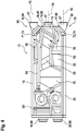
- the concrete structure of the ventilation device 13 is in the FIGS. 3 to 6 explained in more detail.
- the FIG. 3 shows essentially schematically the structure of the ventilation device 13.
- the housing 14 has a front wall 31, a rear wall 32 and a circumferential side wall 33.
- the front wall 31 is removed in the figure 3 and shown displaced in the direction of arrow 35.
- the side wall 33 has a plurality of side wall portions 36, 37, 38 and 39, wherein adjacent to each other Side wall sections 36 to 39 at a 90 ° angle to each other.
- the housing 14 is cuboid, it forms a flat housing, in particular a flat cuboid housing, wherein the flat side 40 of the housing 14 is defined by the side wall 33.
- the housing 14 has a length L having a width B and a height H (which also includes the thickness of the front wall 31).
- the (circumferential) flat side 40 is formed by a plurality of flat side portions 41, 42, 43 and 44, wherein the two of the width B associated flat side portions 41 and 43 flat end faces 45 and 46 of the housing 14 form.
- a plurality of partitions In the interior 34 of the housing 14 of the ventilation device 13 are a plurality of partitions, namely an angled extending partition 47 which extends from the side wall portion 38 to the heat exchanger 15 and two partitions 48 and 49 which extend from the heat exchanger 15 to the side wall portion 36 approximately parallel to each other , Further, partition walls 50 and 51 are provided, which extend from the side wall portion 37 and the side wall portion 39 to the partition wall 47. Moreover, two partition walls 52 and 53 are provided which extend from the side wall portion 37 to the partition wall 48. Due to the partitions 47, 48 and 49 and the heat exchanger 15 and the walls of the housing 14, a first airway 54 and a second airway 55 in the interior 34 of the housing 14 are formed.
- the first airway 54 is with dashed arrow line in FIG.
- the second air path 55 is shown in solid lines arrows FIG. 3 represented and leads from the outside air connection 16 via the heat exchanger 15 to the supply air connection 17, wherein from this second air path 55, an air branch 56 goes off, which is shown with dotted arrow and leads to the supply air port 18.
- the air branch 56 has a first air path 54 crossing, namely under-tunneling air duct 63.
- the partition wall 53 ensures that the air coming from the air duct 63 does not flow into undesired regions of the housing 14, but instead reaches the supply air connection 18.
- the aforementioned bypass flap 61 belongs to a bypass 64, which bypasses the heat exchanger 15 in dependence on the position of the bypass flap 61.
- the bypass air path is in the FIG. 3 indicated by a solid line and an arrow indicated by a dotted line, wherein the bypass 64 has a first air path 54 crossing, namely underthrusting bypass airway 65.
- the partition wall 52 constitutes a boundary wall of the bypass 64. Since the two partition walls 52 and 53 are spaced from each other, there is between them - bounded by a portion of the side wall portion 37 and a portion of the partition wall 48 and covered by portions of the front wall 31 and rear wall 32 an electronics compartment 66 is formed, in which a control and / or regulating electronics of the ventilation unit 13 is housed, with the management of the Ventilation device 13 takes place.
- the heat exchanger 15 performs a heat exchange between air flows passing through the two air paths 54 and 55.
- the outside air connection 16, the supply air connection 17, the further supply air connection 18, the exhaust air connection 19 and the exhaust air connection 20 each have a straight air connection stub 67, which is provided with a seal.
- On the air connection piece 67 can be sealing the air lines 92 ( FIG. 3 ), which are provided with thermal insulation 69 '.
- the air ducts 92 are - according to FIG. 2 -
- the two fans 58 and 60 operate, so that external air is sucked in at the outside air connection 16, which passes through the air filter 59 'and reaches the heat exchanger 15 via the blower 60. From there, the heater 62 is penetrated (which may optionally be in operation) and from there the outside air reaches the two supply air ports 17 and 18.
- the bypass valve 61 it is possible to bypass the heat exchanger 15 or partially bypass That is, the bypass 64 is more or less in function. From the exhaust port 19 exhaust air passes through the air filter 57 and via the heat exchanger 15 and the blower 58 to the smoke dam 59 and from there to the exhaust port 20.
- the heat exchanger 15 ensures a heat exchange between the two aforementioned air flows in the air paths 54 and 55, wherein the heat exchange effect in dependence on the function of the bypass 64 is controllable.
- FIG. 4 shows a further embodiment of a ventilation device 13, which substantially the formation of the ventilation device of FIG. 3 so that only the differences are discussed below.
- the side wall portion 36 is not rectilinear, but formed angled.
- the side wall portion 36 in the embodiment of the FIG. 4 at both of its section ends 69 and 70 an angular shape, whereby angled portions 71 and 72 are formed, each forming an angled wall 73 and 74.
- the arrangement is now made such that the supply air connection 17 is located at the angle wall 74 and the supply air connection 18 at the angle wall 73.
- the two air ports 90 of the other air namely the supply air
- a side wall portion 75 of the side wall portion 36 of the air port 90 of the other type of air, namely the exhaust air is located.
- FIG. 3 only straight air connection stubs 67 are provided.
- arcuate air connection piece 67 are provided for the two supply air connections 17 and 18, which in the mounting position according to FIG. 4 are formed so that all on the right side of the FIG. 4 lying air connections 90 (ie including the straight air connection piece 67 for the exhaust air) have a nozzle center axis 76 of the same direction, ie, the three nozzle center axes 76 parallel to each other.
- FIG. 4 has the embodiment of the ventilation device 13 of FIG. 5 a differently mounted, bent air connection stub 67 with respect to the supply air connection 17.
- the installer will adjust the air connection piece 67 according to a simple wiring and / or due to the structural conditions related alignment.
- FIG. 5 is unlike the embodiments of the Figures 3 and 4 provided that the air channel 63 and the bypass airway 65 is formed as a common air guide 77, in particular as a common Untertunnelung 78 of the first airway 54th Die
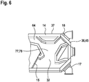
- FIG. 6 illustrates the training of Untertunnelung 78. It is in longitudinal section about Y-shaped with several Arms, wherein a first arm to the bypass 64, a second arm to the supply air port 18 and a third arm to the supply air port 17 (and of course to the heat exchanger 15) leads. Between the first arm and the second arm a reaching to the side wall portion 37 space is formed, which serves to receive components of the ventilation device 13.
- This space is designed in particular as an electronics compartment 66, ie, it receives the control and / or regulating electronics of the ventilation unit 13. Furthermore, in the embodiment of the FIG. 5 the heater 62 is not disposed between the side wall portion 39 and the partition wall 49 (FIGS. 3 and 4), but between the partition wall 47 and the side wall portion 37, between the fan 60 and the air filter 59 '.
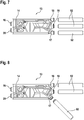
- FIGS. 7 to 10 show different piping arrangements, depending on the design of the air connection piece 67 and alignment of the air connection stub 67 different ways exist to arrange the air handling unit 13 to be connected to air lines 92.
Landscapes
- Engineering & Computer Science (AREA)
- Chemical & Material Sciences (AREA)
- Combustion & Propulsion (AREA)
- Mechanical Engineering (AREA)
- General Engineering & Computer Science (AREA)
- Central Air Conditioning (AREA)
Claims (19)
- Appareil d'aération avec récupération de chaleur, avec un boîtier (14), dans lequel est disposé un échangeur de chaleur (15) pour le transport d'air au moyen d'au moins un ventilateur (58, 60) disposé dans le boîtier (14), le boîtier (14) présentant une paroi avant (31), une paroi arrière (32) et une paroi latérale (33) et des raccordements d'air (90) pour différents types d'air, à savoir air d'alimentation, air d'évacuation, air d'échappement et air extérieur, le raccordement d'air (90) pour l'air d'alimentation étant un raccordement d'air d'alimentation (17, 18), le raccordement d'air (90) pour l'air d'évacuation étant un raccordement d'air d'évacuation (19), le raccordement d'air (90) pour l'air d'échappement étant un raccordement d'air d'échappement (20) et le raccordement d'air (90) pour l'air extérieur étant un raccordement d'air extérieur (16), d'au moins certains des raccordements d'air (90) étant disposés sur la paroi latérale (33) de telle manière qu'un raccordement d'air (90) d'un premier type d'air est situé entre au moins deux raccordements d'air (90) d'un second type d'air, le raccordement d'air (90) du premier type d'air étant le raccordement d'air d'évacuation (19) et les raccordements d'air (90) du second type d'air étant les raccordements d'air d'alimentation (17, 18), le raccordement d'air (90) du premier type d'air présentant une tubulure de raccordement d'air droite (67) et les deux raccordements d'air (90) du second type d'air respectivement présentant une tubulure de raccordement d'air (67) arquée ou angulaire qui peut être tournée ou montée dans une position angulaire souhaitée, un premier chemin d'air (54) qui s'étend à travers l'échangeur de chaleur (15) étant formé dans le boîtier (14), le premier chemin d'air reliant le raccordement d'air d'évacuation (19) avec le raccordement d'air d'échappement (20), et un second chemin d'air (55) qui s'étend à travers l'échangeur de chaleur (15) étant formé dans le boîtier (14), le second chemin d'air reliant le raccordement d'air extérieur (16) avec un des raccordements d'air d'alimentation (17, 18), un branchement d'air (56) du second chemin d'air (55) dans le boîtier (14) menant à l'autre des raccordements d'alimentation d'air (18, 17), et le branchement d'air (56) ayant un conduit d'air (63) croisant le premier chemin d'air (54).
- Appareil d'aération selon la revendication 1, caractérisé en ce que la paroi latérale (33) est une paroi latérale (33) circonférentielle, notamment un côté plat (40) du boîtier (14).
- Appareil d'aération selon l'une quelconque des revendications précédentes, caractérisé en ce que la paroi latérale (33) a plusieurs parties de paroi latérale (36, 37, 38, 39), où les parties de paroi latérale (36, 37, 38, 39) contiguës s'étendent de préférence avec un angle, ou de préférence avec un angle respectif, les unes vers les autres.
- Appareil d'aération selon l'une quelconque des revendications précédentes, caractérisé en ce que l'au moins un ventilateur (58, 60) est disposé dans le boîtier (14).
- Appareil d'aération selon l'une quelconque des revendications précédentes, caractérisé en ce que l'au moins un ventilateur (58, 60), de préférence deux ventilateurs (58, 60), transporte(nt) l'air à partir du raccordement d'air d'évacuation (19) vers le raccordement d'air d'échappement (20), le cas échéant en passant l'échangeur de chaleur (15), et à partir du raccordement d'air extérieur (16) vers le raccordement d'air d'alimentation (17, 18), le cas échéant en passant l'échangeur de chaleur (15).
- Appareil d'aération selon l'une quelconque des revendications précédentes, caractérisé en ce que les au moins certains des raccordements d'air (90) sont disposés sur la paroi latérale (33) de manière affilée.
- Appareil d'aération au moins selon la revendication 3, caractérisé en ce que les au moins certains des raccordements d'air (90) sont disposés sur la même partie de paroi latérale (36, 37, 38, 39).
- Appareil d'aération au moins selon la revendication 3, caractérisé en ce que d'au moins une des parties de paroi latérale (36, 37, 38, 39) s'étend avec un angle au moins sur une de ses deux extrémités de partie (69, 70), la partie angulaire (71, 72) ainsi formée étant une paroi angulaire (73, 74).
- Appareil d'aération selon la revendication 8, caractérisé en ce que d'au moins un des au moins certains des raccordements d'air (90) est disposé sur la paroi angulaire (73, 74).
- Appareil d'aération selon l'une quelconque des revendications précédentes, caractérisé en ce que le boîtier (14) a une forme sensiblement parallélépipédique.
- Appareil d'aération selon l'une quelconque des revendications précédentes, caractérisé en ce que le boîtier (14) est un boîtier plat, notamment un boîtier plat parallélépipédique.
- Appareil d'aération au moins selon la revendication 3, caractérisé en ce que la partie de paroi latérale (36, 37, 38, 39) avec au moins certains des raccordements d'air (90) forme une partie de côté plat (41, 42, 43, 44) du côté plat (40), notamment un côté frontal plat (45, 46) du boîtier (14).
- Appareil d'aération au moins selon la revendication 3, caractérisé en ce que le boîtier (14), notamment le boîtier plat, de préférence le boîtier plat parallélépipédique, présente une partie trapézoïdale de plan horizontal à cause des parois angulaires (73, 74) formées sur les deux extrémités de partie (69, 70) par au moins une des parties de paroi latérale (36, 37, 38, 39).
- Appareil d'aération selon la revendication 13, caractérisé en ce que les deux raccordements d'air (90) de l'autre type d'air sont disposés sur les deux parois angulaires (73, 74) de la partie de paroi latérale (36, 37, 38, 39), et en ce que le raccordement d'air (90) de l'un type d'air est disposé sur une part de paroi latérale (75) de la portion de paroi latérale (36, 37, 38, 39) qui est située entre les deux parois angulaires (73, 74).
- Appareil d'aération selon l'une quelconque des revendications précédentes, caractérisé en ce que les axes centraux (76) de tubulure à côté du raccordement d'au moins certaines des tubulures de raccordement d'air (67) sont parallèles ou sensiblement parallèles.
- Appareil d'aération selon l'une quelconque des revendications précédentes, caractérisé en ce que l'échangeur de chaleur (15) effectue un échange de chaleur entre les deux chemins d'air (54, 55).
- Appareil d'aération selon l'une quelconque des revendications précédentes, caractérisé en ce que le premier ou le second chemin d'air (54, 55) est muni d'une dérivation (64) autour l'échangeur de chaleur (15) pour sélectivement contourner l'échangeur de chaleur (15).
- Appareil d'aération selon la revendication 17, caractérisé en ce que la dérivation (64) présente un chemin de dérivation d'air (65) qui croise, notamment passe sous, le premier chemin d'air (54).
- Appareil d'aération selon la revendication 18, caractérisé en ce que le conduit d'air (63) et le chemin de dérivation d'air (65) sont configurés sous forme d'un guidage commun d'air (77), notamment d'un sous-passage commun (78) sous le premier chemin d'air (54).
Applications Claiming Priority (1)
| Application Number | Priority Date | Filing Date | Title |
|---|---|---|---|
| DE102013016498.2A DE102013016498A1 (de) | 2013-10-02 | 2013-10-02 | Lüftungsgerät mit Wärmerückgewinnung |
Publications (2)
| Publication Number | Publication Date |
|---|---|
| EP2857772A1 EP2857772A1 (fr) | 2015-04-08 |
| EP2857772B1 true EP2857772B1 (fr) | 2019-12-11 |
Family
ID=51589080
Family Applications (1)
| Application Number | Title | Priority Date | Filing Date |
|---|---|---|---|
| EP14184209.6A Active EP2857772B1 (fr) | 2013-10-02 | 2014-09-10 | Appareil d'aération avec récupération de chaleur |
Country Status (2)
| Country | Link |
|---|---|
| EP (1) | EP2857772B1 (fr) |
| DE (1) | DE102013016498A1 (fr) |
Families Citing this family (2)
| Publication number | Priority date | Publication date | Assignee | Title |
|---|---|---|---|---|
| CN113324303A (zh) * | 2020-02-12 | 2021-08-31 | 青岛海尔空调电子有限公司 | 具有双层风道的全热新风机 |
| FR3160451A1 (fr) * | 2024-03-20 | 2025-09-26 | Aldes Aeraulique | Caisson de ventilation mécanique contrôlée à double flux comprenant une paroi de séparation qui a une forme courbée |
Family Cites Families (6)
| Publication number | Priority date | Publication date | Assignee | Title |
|---|---|---|---|---|
| US5722483A (en) * | 1996-08-14 | 1998-03-03 | Gibson; Gary L. | Air exchange apparatus and method |
| CA2306022A1 (fr) * | 2000-04-18 | 2001-10-18 | Peter Beaini | Systeme de ventilation et de recuperation de chaleur sans conduite ni pieces mobiles |
| DE10109753A1 (de) * | 2001-02-28 | 2002-09-05 | Woelfle Gmbh | Lüftungsgerät für die Gebäudelüftung |
| JP4432369B2 (ja) * | 2003-05-30 | 2010-03-17 | ダイキン工業株式会社 | 調湿装置 |
| FR2942531B1 (fr) * | 2009-02-24 | 2011-12-09 | Aldes Aeraulique | Caisson de distribution d'air. |
| ES1071624Y (es) * | 2010-01-11 | 2010-06-15 | Soler & Palau Res S L U | Dispositivo para ventilacion mecanica controlada |
-
2013
- 2013-10-02 DE DE102013016498.2A patent/DE102013016498A1/de not_active Ceased
-
2014
- 2014-09-10 EP EP14184209.6A patent/EP2857772B1/fr active Active
Non-Patent Citations (1)
| Title |
|---|
| None * |
Also Published As
| Publication number | Publication date |
|---|---|
| EP2857772A1 (fr) | 2015-04-08 |
| DE102013016498A1 (de) | 2015-04-02 |
Similar Documents
| Publication | Publication Date | Title |
|---|---|---|
| EP0497296B1 (fr) | Installation de filtre-ventilateur pour l'utilisation dans des salles blanches | |
| EP2479508B1 (fr) | Système de répartition de l'air | |
| EP1411303B1 (fr) | Elément de régulation de la température d'une enceinte et son agencement | |
| EP3168545B1 (fr) | Installation de rideau d'air | |
| EP2288854B1 (fr) | Raccord en t, en particulier pour un système de ventilation | |
| DE102019105934A1 (de) | Schalldämmanordnung | |
| EP2354686B9 (fr) | Sortie d'air frais et induction d'air récirculé d'une pièce en direction horizontale d'un climatisateur | |
| EP2857772A1 (fr) | Appareil d'aération avec récupération de chaleur | |
| EP2245377B1 (fr) | Bâtiment avec un système de ventilation et procédé pour transformer un bâtiment éxistant en un tel bâtiment | |
| EP0059410A2 (fr) | Armoire pour l'insertion d'éléments électriques et/ou électroniques | |
| DE202016100528U1 (de) | Fassadenanschlusseinrichtung für eine Lüftungseinrichtung sowie Lüftungseinrichtung | |
| DE102014001447A1 (de) | Kühlanlage mit wenigstens einer Ventilatoranordnung | |
| DE202007001429U1 (de) | Einrichtung zum Heizen, Kühlen und/oder Lüften eines Raumes eines Gebäudes | |
| AT511366B1 (de) | Lüftungskasten | |
| EP3002173A1 (fr) | Vehicule sur rail dote d'un conduit de climatiseur de toit | |
| DE202019100467U1 (de) | Lufteinlass und Anordnung zur Führung von Luft | |
| DE102013203625B4 (de) | Dezentrales lüftungsgerät mit wärmerückgewinnung | |
| EP3587943A2 (fr) | Dispositif d'aération et de mise en température d'une pièce dans un bâtiment | |
| DE19525551B4 (de) | Anschlußkasten | |
| EP1947398B1 (fr) | Dispositif de chauffage, refroidissement et/ou aération d'une salle d'un bâtiment | |
| EP2431679B1 (fr) | Système d'aération d'espace | |
| DE20019943U1 (de) | Mehrfach-Heizungsanschlussanordnung und Heizkörper | |
| EP2708828A2 (fr) | Agencement d'appareil de ventilation | |
| DE202016102068U1 (de) | Luftleitblende und Deckenkassette mit Luftleitblende | |
| EP4151916A1 (fr) | Dispositif d'aération et procédé de fonctionnement d'un dispositif d'aération |
Legal Events
| Date | Code | Title | Description |
|---|---|---|---|
| PUAI | Public reference made under article 153(3) epc to a published international application that has entered the european phase |
Free format text: ORIGINAL CODE: 0009012 |
|
| 17P | Request for examination filed |
Effective date: 20140910 |
|
| AK | Designated contracting states |
Kind code of ref document: A1 Designated state(s): AL AT BE BG CH CY CZ DE DK EE ES FI FR GB GR HR HU IE IS IT LI LT LU LV MC MK MT NL NO PL PT RO RS SE SI SK SM TR |
|
| AX | Request for extension of the european patent |
Extension state: BA ME |
|
| R17P | Request for examination filed (corrected) |
Effective date: 20150518 |
|
| RBV | Designated contracting states (corrected) |
Designated state(s): AL AT BE BG CH CY CZ DE DK EE ES FI FR GB GR HR HU IE IS IT LI LT LU LV MC MK MT NL NO PL PT RO RS SE SI SK SM TR |
|
| RIN1 | Information on inventor provided before grant (corrected) |
Inventor name: KAMMERER, STEFAN |
|
| GRAP | Despatch of communication of intention to grant a patent |
Free format text: ORIGINAL CODE: EPIDOSNIGR1 |
|
| STAA | Information on the status of an ep patent application or granted ep patent |
Free format text: STATUS: GRANT OF PATENT IS INTENDED |
|
| INTG | Intention to grant announced |
Effective date: 20190128 |
|
| GRAS | Grant fee paid |
Free format text: ORIGINAL CODE: EPIDOSNIGR3 |
|
| GRAJ | Information related to disapproval of communication of intention to grant by the applicant or resumption of examination proceedings by the epo deleted |
Free format text: ORIGINAL CODE: EPIDOSDIGR1 |
|
| GRAL | Information related to payment of fee for publishing/printing deleted |
Free format text: ORIGINAL CODE: EPIDOSDIGR3 |
|
| STAA | Information on the status of an ep patent application or granted ep patent |
Free format text: STATUS: REQUEST FOR EXAMINATION WAS MADE |
|
| GRAP | Despatch of communication of intention to grant a patent |
Free format text: ORIGINAL CODE: EPIDOSNIGR1 |
|
| STAA | Information on the status of an ep patent application or granted ep patent |
Free format text: STATUS: GRANT OF PATENT IS INTENDED |
|
| INTC | Intention to grant announced (deleted) | ||
| INTG | Intention to grant announced |
Effective date: 20190716 |
|
| GRAA | (expected) grant |
Free format text: ORIGINAL CODE: 0009210 |
|
| STAA | Information on the status of an ep patent application or granted ep patent |
Free format text: STATUS: THE PATENT HAS BEEN GRANTED |
|
| AK | Designated contracting states |
Kind code of ref document: B1 Designated state(s): AL AT BE BG CH CY CZ DE DK EE ES FI FR GB GR HR HU IE IS IT LI LT LU LV MC MK MT NL NO PL PT RO RS SE SI SK SM TR |
|
| REG | Reference to a national code |
Ref country code: GB Ref legal event code: FG4D Free format text: NOT ENGLISH |
|
| REG | Reference to a national code |
Ref country code: CH Ref legal event code: EP |
|
| REG | Reference to a national code |
Ref country code: AT Ref legal event code: REF Ref document number: 1212577 Country of ref document: AT Kind code of ref document: T Effective date: 20191215 |
|
| REG | Reference to a national code |
Ref country code: DE Ref legal event code: R096 Ref document number: 502014013221 Country of ref document: DE |
|
| REG | Reference to a national code |
Ref country code: IE Ref legal event code: FG4D Free format text: LANGUAGE OF EP DOCUMENT: GERMAN |
|
| REG | Reference to a national code |
Ref country code: CH Ref legal event code: NV Representative=s name: OFFICE ERNEST T. FREYLINGER S.A., CH |
|
| REG | Reference to a national code |
Ref country code: NL Ref legal event code: MP Effective date: 20191211 |
|
| REG | Reference to a national code |
Ref country code: LT Ref legal event code: MG4D |
|
| PG25 | Lapsed in a contracting state [announced via postgrant information from national office to epo] |
Ref country code: LT Free format text: LAPSE BECAUSE OF FAILURE TO SUBMIT A TRANSLATION OF THE DESCRIPTION OR TO PAY THE FEE WITHIN THE PRESCRIBED TIME-LIMIT Effective date: 20191211 Ref country code: GR Free format text: LAPSE BECAUSE OF FAILURE TO SUBMIT A TRANSLATION OF THE DESCRIPTION OR TO PAY THE FEE WITHIN THE PRESCRIBED TIME-LIMIT Effective date: 20200312 Ref country code: NO Free format text: LAPSE BECAUSE OF FAILURE TO SUBMIT A TRANSLATION OF THE DESCRIPTION OR TO PAY THE FEE WITHIN THE PRESCRIBED TIME-LIMIT Effective date: 20200311 Ref country code: SE Free format text: LAPSE BECAUSE OF FAILURE TO SUBMIT A TRANSLATION OF THE DESCRIPTION OR TO PAY THE FEE WITHIN THE PRESCRIBED TIME-LIMIT Effective date: 20191211 Ref country code: LV Free format text: LAPSE BECAUSE OF FAILURE TO SUBMIT A TRANSLATION OF THE DESCRIPTION OR TO PAY THE FEE WITHIN THE PRESCRIBED TIME-LIMIT Effective date: 20191211 Ref country code: FI Free format text: LAPSE BECAUSE OF FAILURE TO SUBMIT A TRANSLATION OF THE DESCRIPTION OR TO PAY THE FEE WITHIN THE PRESCRIBED TIME-LIMIT Effective date: 20191211 Ref country code: BG Free format text: LAPSE BECAUSE OF FAILURE TO SUBMIT A TRANSLATION OF THE DESCRIPTION OR TO PAY THE FEE WITHIN THE PRESCRIBED TIME-LIMIT Effective date: 20200311 Ref country code: ES Free format text: LAPSE BECAUSE OF FAILURE TO SUBMIT A TRANSLATION OF THE DESCRIPTION OR TO PAY THE FEE WITHIN THE PRESCRIBED TIME-LIMIT Effective date: 20191211 |
|
| PG25 | Lapsed in a contracting state [announced via postgrant information from national office to epo] |
Ref country code: HR Free format text: LAPSE BECAUSE OF FAILURE TO SUBMIT A TRANSLATION OF THE DESCRIPTION OR TO PAY THE FEE WITHIN THE PRESCRIBED TIME-LIMIT Effective date: 20191211 Ref country code: RS Free format text: LAPSE BECAUSE OF FAILURE TO SUBMIT A TRANSLATION OF THE DESCRIPTION OR TO PAY THE FEE WITHIN THE PRESCRIBED TIME-LIMIT Effective date: 20191211 |
|
| PG25 | Lapsed in a contracting state [announced via postgrant information from national office to epo] |
Ref country code: AL Free format text: LAPSE BECAUSE OF FAILURE TO SUBMIT A TRANSLATION OF THE DESCRIPTION OR TO PAY THE FEE WITHIN THE PRESCRIBED TIME-LIMIT Effective date: 20191211 |
|
| PG25 | Lapsed in a contracting state [announced via postgrant information from national office to epo] |
Ref country code: RO Free format text: LAPSE BECAUSE OF FAILURE TO SUBMIT A TRANSLATION OF THE DESCRIPTION OR TO PAY THE FEE WITHIN THE PRESCRIBED TIME-LIMIT Effective date: 20191211 Ref country code: CZ Free format text: LAPSE BECAUSE OF FAILURE TO SUBMIT A TRANSLATION OF THE DESCRIPTION OR TO PAY THE FEE WITHIN THE PRESCRIBED TIME-LIMIT Effective date: 20191211 Ref country code: NL Free format text: LAPSE BECAUSE OF FAILURE TO SUBMIT A TRANSLATION OF THE DESCRIPTION OR TO PAY THE FEE WITHIN THE PRESCRIBED TIME-LIMIT Effective date: 20191211 Ref country code: PT Free format text: LAPSE BECAUSE OF FAILURE TO SUBMIT A TRANSLATION OF THE DESCRIPTION OR TO PAY THE FEE WITHIN THE PRESCRIBED TIME-LIMIT Effective date: 20200506 Ref country code: EE Free format text: LAPSE BECAUSE OF FAILURE TO SUBMIT A TRANSLATION OF THE DESCRIPTION OR TO PAY THE FEE WITHIN THE PRESCRIBED TIME-LIMIT Effective date: 20191211 |
|
| PG25 | Lapsed in a contracting state [announced via postgrant information from national office to epo] |
Ref country code: SM Free format text: LAPSE BECAUSE OF FAILURE TO SUBMIT A TRANSLATION OF THE DESCRIPTION OR TO PAY THE FEE WITHIN THE PRESCRIBED TIME-LIMIT Effective date: 20191211 Ref country code: SK Free format text: LAPSE BECAUSE OF FAILURE TO SUBMIT A TRANSLATION OF THE DESCRIPTION OR TO PAY THE FEE WITHIN THE PRESCRIBED TIME-LIMIT Effective date: 20191211 Ref country code: IS Free format text: LAPSE BECAUSE OF FAILURE TO SUBMIT A TRANSLATION OF THE DESCRIPTION OR TO PAY THE FEE WITHIN THE PRESCRIBED TIME-LIMIT Effective date: 20200411 |
|
| REG | Reference to a national code |
Ref country code: DE Ref legal event code: R097 Ref document number: 502014013221 Country of ref document: DE |
|
| PLBE | No opposition filed within time limit |
Free format text: ORIGINAL CODE: 0009261 |
|
| STAA | Information on the status of an ep patent application or granted ep patent |
Free format text: STATUS: NO OPPOSITION FILED WITHIN TIME LIMIT |
|
| PG25 | Lapsed in a contracting state [announced via postgrant information from national office to epo] |
Ref country code: DK Free format text: LAPSE BECAUSE OF FAILURE TO SUBMIT A TRANSLATION OF THE DESCRIPTION OR TO PAY THE FEE WITHIN THE PRESCRIBED TIME-LIMIT Effective date: 20191211 |
|
| PGFP | Annual fee paid to national office [announced via postgrant information from national office to epo] |
Ref country code: DE Payment date: 20200917 Year of fee payment: 7 |
|
| 26N | No opposition filed |
Effective date: 20200914 |
|
| PG25 | Lapsed in a contracting state [announced via postgrant information from national office to epo] |
Ref country code: SI Free format text: LAPSE BECAUSE OF FAILURE TO SUBMIT A TRANSLATION OF THE DESCRIPTION OR TO PAY THE FEE WITHIN THE PRESCRIBED TIME-LIMIT Effective date: 20191211 Ref country code: PL Free format text: LAPSE BECAUSE OF FAILURE TO SUBMIT A TRANSLATION OF THE DESCRIPTION OR TO PAY THE FEE WITHIN THE PRESCRIBED TIME-LIMIT Effective date: 20191211 |
|
| PGFP | Annual fee paid to national office [announced via postgrant information from national office to epo] |
Ref country code: CH Payment date: 20200921 Year of fee payment: 7 Ref country code: AT Payment date: 20200921 Year of fee payment: 7 |
|
| PG25 | Lapsed in a contracting state [announced via postgrant information from national office to epo] |
Ref country code: IT Free format text: LAPSE BECAUSE OF FAILURE TO SUBMIT A TRANSLATION OF THE DESCRIPTION OR TO PAY THE FEE WITHIN THE PRESCRIBED TIME-LIMIT Effective date: 20191211 |
|
| PG25 | Lapsed in a contracting state [announced via postgrant information from national office to epo] |
Ref country code: MC Free format text: LAPSE BECAUSE OF FAILURE TO SUBMIT A TRANSLATION OF THE DESCRIPTION OR TO PAY THE FEE WITHIN THE PRESCRIBED TIME-LIMIT Effective date: 20191211 |
|
| GBPC | Gb: european patent ceased through non-payment of renewal fee |
Effective date: 20200910 |
|
| REG | Reference to a national code |
Ref country code: BE Ref legal event code: MM Effective date: 20200930 |
|
| PG25 | Lapsed in a contracting state [announced via postgrant information from national office to epo] |
Ref country code: LU Free format text: LAPSE BECAUSE OF NON-PAYMENT OF DUE FEES Effective date: 20200910 |
|
| PG25 | Lapsed in a contracting state [announced via postgrant information from national office to epo] |
Ref country code: FR Free format text: LAPSE BECAUSE OF NON-PAYMENT OF DUE FEES Effective date: 20200930 |
|
| PG25 | Lapsed in a contracting state [announced via postgrant information from national office to epo] |
Ref country code: BE Free format text: LAPSE BECAUSE OF NON-PAYMENT OF DUE FEES Effective date: 20200930 Ref country code: GB Free format text: LAPSE BECAUSE OF NON-PAYMENT OF DUE FEES Effective date: 20200910 Ref country code: IE Free format text: LAPSE BECAUSE OF NON-PAYMENT OF DUE FEES Effective date: 20200910 |
|
| REG | Reference to a national code |
Ref country code: DE Ref legal event code: R119 Ref document number: 502014013221 Country of ref document: DE |
|
| REG | Reference to a national code |
Ref country code: CH Ref legal event code: PL |
|
| REG | Reference to a national code |
Ref country code: AT Ref legal event code: MM01 Ref document number: 1212577 Country of ref document: AT Kind code of ref document: T Effective date: 20210910 |
|
| PG25 | Lapsed in a contracting state [announced via postgrant information from national office to epo] |
Ref country code: TR Free format text: LAPSE BECAUSE OF FAILURE TO SUBMIT A TRANSLATION OF THE DESCRIPTION OR TO PAY THE FEE WITHIN THE PRESCRIBED TIME-LIMIT Effective date: 20191211 Ref country code: MT Free format text: LAPSE BECAUSE OF FAILURE TO SUBMIT A TRANSLATION OF THE DESCRIPTION OR TO PAY THE FEE WITHIN THE PRESCRIBED TIME-LIMIT Effective date: 20191211 Ref country code: CY Free format text: LAPSE BECAUSE OF FAILURE TO SUBMIT A TRANSLATION OF THE DESCRIPTION OR TO PAY THE FEE WITHIN THE PRESCRIBED TIME-LIMIT Effective date: 20191211 |
|
| PG25 | Lapsed in a contracting state [announced via postgrant information from national office to epo] |
Ref country code: MK Free format text: LAPSE BECAUSE OF FAILURE TO SUBMIT A TRANSLATION OF THE DESCRIPTION OR TO PAY THE FEE WITHIN THE PRESCRIBED TIME-LIMIT Effective date: 20191211 |
|
| PG25 | Lapsed in a contracting state [announced via postgrant information from national office to epo] |
Ref country code: DE Free format text: LAPSE BECAUSE OF NON-PAYMENT OF DUE FEES Effective date: 20220401 |
|
| PG25 | Lapsed in a contracting state [announced via postgrant information from national office to epo] |
Ref country code: LI Free format text: LAPSE BECAUSE OF NON-PAYMENT OF DUE FEES Effective date: 20210930 Ref country code: CH Free format text: LAPSE BECAUSE OF NON-PAYMENT OF DUE FEES Effective date: 20210930 Ref country code: AT Free format text: LAPSE BECAUSE OF NON-PAYMENT OF DUE FEES Effective date: 20210910 |