EP2857784B1 - Wärmespeichervorrichtung - Google Patents
Wärmespeichervorrichtung Download PDFInfo
- Publication number
- EP2857784B1 EP2857784B1 EP13791146.7A EP13791146A EP2857784B1 EP 2857784 B1 EP2857784 B1 EP 2857784B1 EP 13791146 A EP13791146 A EP 13791146A EP 2857784 B1 EP2857784 B1 EP 2857784B1
- Authority
- EP
- European Patent Office
- Prior art keywords
- ammonia
- reservoir
- ammonia reservoir
- storage device
- heat storage
- Prior art date
- Legal status (The legal status is an assumption and is not a legal conclusion. Google has not performed a legal analysis and makes no representation as to the accuracy of the status listed.)
- Not-in-force
Links
- 0 CCC(C(C1)C(*C)CCCC1N)C(C)=C Chemical compound CCC(C(C1)C(*C)CCCC1N)C(C)=C 0.000 description 1
Images



Classifications
-
- F—MECHANICAL ENGINEERING; LIGHTING; HEATING; WEAPONS; BLASTING
- F01—MACHINES OR ENGINES IN GENERAL; ENGINE PLANTS IN GENERAL; STEAM ENGINES
- F01N—GAS-FLOW SILENCERS OR EXHAUST APPARATUS FOR MACHINES OR ENGINES IN GENERAL; GAS-FLOW SILENCERS OR EXHAUST APPARATUS FOR INTERNAL-COMBUSTION ENGINES
- F01N3/00—Exhaust or silencing apparatus having means for purifying, rendering innocuous, or otherwise treating exhaust
- F01N3/08—Exhaust or silencing apparatus having means for purifying, rendering innocuous, or otherwise treating exhaust for rendering innocuous
- F01N3/10—Exhaust or silencing apparatus having means for purifying, rendering innocuous, or otherwise treating exhaust for rendering innocuous by thermal or catalytic conversion of noxious components of exhaust
- F01N3/18—Exhaust or silencing apparatus having means for purifying, rendering innocuous, or otherwise treating exhaust for rendering innocuous by thermal or catalytic conversion of noxious components of exhaust characterised by methods of operation; Control
- F01N3/20—Exhaust or silencing apparatus having means for purifying, rendering innocuous, or otherwise treating exhaust for rendering innocuous by thermal or catalytic conversion of noxious components of exhaust characterised by methods of operation; Control specially adapted for catalytic conversion
- F01N3/2006—Periodically heating or cooling catalytic reactors, e.g. at cold starting or overheating
-
- C—CHEMISTRY; METALLURGY
- C09—DYES; PAINTS; POLISHES; NATURAL RESINS; ADHESIVES; COMPOSITIONS NOT OTHERWISE PROVIDED FOR; APPLICATIONS OF MATERIALS NOT OTHERWISE PROVIDED FOR
- C09K—MATERIALS FOR MISCELLANEOUS APPLICATIONS, NOT PROVIDED FOR ELSEWHERE
- C09K5/00—Heat-transfer, heat-exchange or heat-storage materials, e.g. refrigerants; Materials for the production of heat or cold by chemical reactions other than by combustion
- C09K5/16—Materials undergoing chemical reactions when used
-
- F—MECHANICAL ENGINEERING; LIGHTING; HEATING; WEAPONS; BLASTING
- F01—MACHINES OR ENGINES IN GENERAL; ENGINE PLANTS IN GENERAL; STEAM ENGINES
- F01N—GAS-FLOW SILENCERS OR EXHAUST APPARATUS FOR MACHINES OR ENGINES IN GENERAL; GAS-FLOW SILENCERS OR EXHAUST APPARATUS FOR INTERNAL-COMBUSTION ENGINES
- F01N3/00—Exhaust or silencing apparatus having means for purifying, rendering innocuous, or otherwise treating exhaust
- F01N3/08—Exhaust or silencing apparatus having means for purifying, rendering innocuous, or otherwise treating exhaust for rendering innocuous
- F01N3/10—Exhaust or silencing apparatus having means for purifying, rendering innocuous, or otherwise treating exhaust for rendering innocuous by thermal or catalytic conversion of noxious components of exhaust
- F01N3/105—General auxiliary catalysts, e.g. upstream or downstream of the main catalyst
- F01N3/106—Auxiliary oxidation catalysts
-
- F—MECHANICAL ENGINEERING; LIGHTING; HEATING; WEAPONS; BLASTING
- F01—MACHINES OR ENGINES IN GENERAL; ENGINE PLANTS IN GENERAL; STEAM ENGINES
- F01N—GAS-FLOW SILENCERS OR EXHAUST APPARATUS FOR MACHINES OR ENGINES IN GENERAL; GAS-FLOW SILENCERS OR EXHAUST APPARATUS FOR INTERNAL-COMBUSTION ENGINES
- F01N3/00—Exhaust or silencing apparatus having means for purifying, rendering innocuous, or otherwise treating exhaust
- F01N3/08—Exhaust or silencing apparatus having means for purifying, rendering innocuous, or otherwise treating exhaust for rendering innocuous
- F01N3/10—Exhaust or silencing apparatus having means for purifying, rendering innocuous, or otherwise treating exhaust for rendering innocuous by thermal or catalytic conversion of noxious components of exhaust
- F01N3/24—Exhaust or silencing apparatus having means for purifying, rendering innocuous, or otherwise treating exhaust for rendering innocuous by thermal or catalytic conversion of noxious components of exhaust characterised by constructional aspects of converting apparatus
-
- F—MECHANICAL ENGINEERING; LIGHTING; HEATING; WEAPONS; BLASTING
- F28—HEAT EXCHANGE IN GENERAL
- F28D—HEAT-EXCHANGE APPARATUS, NOT PROVIDED FOR IN ANOTHER SUBCLASS, IN WHICH THE HEAT-EXCHANGE MEDIA DO NOT COME INTO DIRECT CONTACT
- F28D1/00—Heat-exchange apparatus having stationary conduit assemblies for one heat-exchange medium only, the media being in contact with different sides of the conduit wall, in which the other heat-exchange medium is a large body of fluid, e.g. domestic or motor car radiators
- F28D1/02—Heat-exchange apparatus having stationary conduit assemblies for one heat-exchange medium only, the media being in contact with different sides of the conduit wall, in which the other heat-exchange medium is a large body of fluid, e.g. domestic or motor car radiators with heat-exchange conduits immersed in the body of fluid
- F28D1/0233—Heat-exchange apparatus having stationary conduit assemblies for one heat-exchange medium only, the media being in contact with different sides of the conduit wall, in which the other heat-exchange medium is a large body of fluid, e.g. domestic or motor car radiators with heat-exchange conduits immersed in the body of fluid with air flow channels
-
- F—MECHANICAL ENGINEERING; LIGHTING; HEATING; WEAPONS; BLASTING
- F28—HEAT EXCHANGE IN GENERAL
- F28D—HEAT-EXCHANGE APPARATUS, NOT PROVIDED FOR IN ANOTHER SUBCLASS, IN WHICH THE HEAT-EXCHANGE MEDIA DO NOT COME INTO DIRECT CONTACT
- F28D20/00—Heat storage plants or apparatus in general; Regenerative heat-exchange apparatus not covered by groups F28D17/00 or F28D19/00
-
- F—MECHANICAL ENGINEERING; LIGHTING; HEATING; WEAPONS; BLASTING
- F28—HEAT EXCHANGE IN GENERAL
- F28D—HEAT-EXCHANGE APPARATUS, NOT PROVIDED FOR IN ANOTHER SUBCLASS, IN WHICH THE HEAT-EXCHANGE MEDIA DO NOT COME INTO DIRECT CONTACT
- F28D20/00—Heat storage plants or apparatus in general; Regenerative heat-exchange apparatus not covered by groups F28D17/00 or F28D19/00
- F28D20/003—Heat storage plants or apparatus in general; Regenerative heat-exchange apparatus not covered by groups F28D17/00 or F28D19/00 using thermochemical reactions
-
- F—MECHANICAL ENGINEERING; LIGHTING; HEATING; WEAPONS; BLASTING
- F28—HEAT EXCHANGE IN GENERAL
- F28F—DETAILS OF HEAT-EXCHANGE AND HEAT-TRANSFER APPARATUS, OF GENERAL APPLICATION
- F28F3/00—Plate-like or laminated elements; Assemblies of plate-like or laminated elements
- F28F3/02—Elements or assemblies thereof with means for increasing heat-transfer area, e.g. with fins, with recesses, with corrugations
-
- F—MECHANICAL ENGINEERING; LIGHTING; HEATING; WEAPONS; BLASTING
- F01—MACHINES OR ENGINES IN GENERAL; ENGINE PLANTS IN GENERAL; STEAM ENGINES
- F01N—GAS-FLOW SILENCERS OR EXHAUST APPARATUS FOR MACHINES OR ENGINES IN GENERAL; GAS-FLOW SILENCERS OR EXHAUST APPARATUS FOR INTERNAL-COMBUSTION ENGINES
- F01N2240/00—Combination or association of two or more different exhaust treating devices, or of at least one such device with an auxiliary device, not covered by indexing codes F01N2230/00 or F01N2250/00, one of the devices being
- F01N2240/02—Combination or association of two or more different exhaust treating devices, or of at least one such device with an auxiliary device, not covered by indexing codes F01N2230/00 or F01N2250/00, one of the devices being a heat exchanger
-
- F—MECHANICAL ENGINEERING; LIGHTING; HEATING; WEAPONS; BLASTING
- F01—MACHINES OR ENGINES IN GENERAL; ENGINE PLANTS IN GENERAL; STEAM ENGINES
- F01N—GAS-FLOW SILENCERS OR EXHAUST APPARATUS FOR MACHINES OR ENGINES IN GENERAL; GAS-FLOW SILENCERS OR EXHAUST APPARATUS FOR INTERNAL-COMBUSTION ENGINES
- F01N2260/00—Exhaust treating devices having provisions not otherwise provided for
- F01N2260/08—Exhaust treating devices having provisions not otherwise provided for for preventing heat loss or temperature drop, using other means than layers of heat-insulating material
-
- F—MECHANICAL ENGINEERING; LIGHTING; HEATING; WEAPONS; BLASTING
- F01—MACHINES OR ENGINES IN GENERAL; ENGINE PLANTS IN GENERAL; STEAM ENGINES
- F01N—GAS-FLOW SILENCERS OR EXHAUST APPARATUS FOR MACHINES OR ENGINES IN GENERAL; GAS-FLOW SILENCERS OR EXHAUST APPARATUS FOR INTERNAL-COMBUSTION ENGINES
- F01N2550/00—Monitoring or diagnosing the deterioration of exhaust systems
- F01N2550/14—Systems for adding secondary air into exhaust
-
- F—MECHANICAL ENGINEERING; LIGHTING; HEATING; WEAPONS; BLASTING
- F01—MACHINES OR ENGINES IN GENERAL; ENGINE PLANTS IN GENERAL; STEAM ENGINES
- F01N—GAS-FLOW SILENCERS OR EXHAUST APPARATUS FOR MACHINES OR ENGINES IN GENERAL; GAS-FLOW SILENCERS OR EXHAUST APPARATUS FOR INTERNAL-COMBUSTION ENGINES
- F01N2570/00—Exhaust treating apparatus eliminating, absorbing or adsorbing specific elements or compounds
- F01N2570/18—Ammonia
-
- F—MECHANICAL ENGINEERING; LIGHTING; HEATING; WEAPONS; BLASTING
- F01—MACHINES OR ENGINES IN GENERAL; ENGINE PLANTS IN GENERAL; STEAM ENGINES
- F01N—GAS-FLOW SILENCERS OR EXHAUST APPARATUS FOR MACHINES OR ENGINES IN GENERAL; GAS-FLOW SILENCERS OR EXHAUST APPARATUS FOR INTERNAL-COMBUSTION ENGINES
- F01N2610/00—Adding substances to exhaust gases
- F01N2610/14—Arrangements for the supply of substances, e.g. conduits
- F01N2610/1406—Storage means for substances, e.g. tanks or reservoirs
-
- F—MECHANICAL ENGINEERING; LIGHTING; HEATING; WEAPONS; BLASTING
- F28—HEAT EXCHANGE IN GENERAL
- F28D—HEAT-EXCHANGE APPARATUS, NOT PROVIDED FOR IN ANOTHER SUBCLASS, IN WHICH THE HEAT-EXCHANGE MEDIA DO NOT COME INTO DIRECT CONTACT
- F28D21/00—Heat-exchange apparatus not covered by any of the groups F28D1/00 - F28D20/00
- F28D2021/0019—Other heat exchangers for particular applications; Heat exchange systems not otherwise provided for
- F28D2021/008—Other heat exchangers for particular applications; Heat exchange systems not otherwise provided for for vehicles
-
- Y—GENERAL TAGGING OF NEW TECHNOLOGICAL DEVELOPMENTS; GENERAL TAGGING OF CROSS-SECTIONAL TECHNOLOGIES SPANNING OVER SEVERAL SECTIONS OF THE IPC; TECHNICAL SUBJECTS COVERED BY FORMER USPC CROSS-REFERENCE ART COLLECTIONS [XRACs] AND DIGESTS
- Y02—TECHNOLOGIES OR APPLICATIONS FOR MITIGATION OR ADAPTATION AGAINST CLIMATE CHANGE
- Y02A—TECHNOLOGIES FOR ADAPTATION TO CLIMATE CHANGE
- Y02A50/00—TECHNOLOGIES FOR ADAPTATION TO CLIMATE CHANGE in human health protection, e.g. against extreme weather
- Y02A50/20—Air quality improvement or preservation, e.g. vehicle emission control or emission reduction by using catalytic converters
-
- Y—GENERAL TAGGING OF NEW TECHNOLOGICAL DEVELOPMENTS; GENERAL TAGGING OF CROSS-SECTIONAL TECHNOLOGIES SPANNING OVER SEVERAL SECTIONS OF THE IPC; TECHNICAL SUBJECTS COVERED BY FORMER USPC CROSS-REFERENCE ART COLLECTIONS [XRACs] AND DIGESTS
- Y02—TECHNOLOGIES OR APPLICATIONS FOR MITIGATION OR ADAPTATION AGAINST CLIMATE CHANGE
- Y02E—REDUCTION OF GREENHOUSE GAS [GHG] EMISSIONS, RELATED TO ENERGY GENERATION, TRANSMISSION OR DISTRIBUTION
- Y02E60/00—Enabling technologies; Technologies with a potential or indirect contribution to GHG emissions mitigation
- Y02E60/14—Thermal energy storage
-
- Y—GENERAL TAGGING OF NEW TECHNOLOGICAL DEVELOPMENTS; GENERAL TAGGING OF CROSS-SECTIONAL TECHNOLOGIES SPANNING OVER SEVERAL SECTIONS OF THE IPC; TECHNICAL SUBJECTS COVERED BY FORMER USPC CROSS-REFERENCE ART COLLECTIONS [XRACs] AND DIGESTS
- Y02—TECHNOLOGIES OR APPLICATIONS FOR MITIGATION OR ADAPTATION AGAINST CLIMATE CHANGE
- Y02T—CLIMATE CHANGE MITIGATION TECHNOLOGIES RELATED TO TRANSPORTATION
- Y02T10/00—Road transport of goods or passengers
- Y02T10/10—Internal combustion engine [ICE] based vehicles
- Y02T10/12—Improving ICE efficiencies
Definitions
- the present invention relates to a heat storage device provided in an exhaust system of an internal-combustion engine of a vehicle.
- Patent Literature 1 As a heat storage device, one disclosed in Patent Literature 1 has been known, for example.
- the heat storage device disclosed in Patent Literature 1 comprises a reaction vessel for containing a heat storage member which reversibly causes exothermic and endothermic reactions with a reaction medium, a storage vessel for storing the reaction medium, a communication passage for communicating the reaction and storage vessels to each other, so as to enable the reaction medium to circulate between the reaction and storage vessels, and a heater for heating the reaction medium in the storage vessel.
- Patent Literature 1 Japanese Patent Application Laid-Open No. 2011-208865
- ammonia NH 3
- ammonia reservoir a storage vessel
- ammonia reservoir Once ammonia is separated from the absorbent of the ammonia reservoir when generating heat from the heat storage member, the temperature of the ammonia reservoir drops. When its temperature drops, the ammonia reservoir is hard to supply ammonia to the heat storage member. This makes it necessary to keep the ammonia reservoir at a desirable temperature.
- a heater is used for the temperature control of the ammonia reservoir as in the above-mentioned prior art, power is required for operating the heater, which incurs energy loss.
- the present invention is a heat storage device according to claim 1 for heating a catalyst arranged in an exhaust system of an internal-combustion engine of a vehicle, the heat storage device comprising a reactor, arranged in the exhaust system, having a formed body chemically reacting with ammonia and generating heat; and an ammonia reservoir, connected to the reactor, for storing the ammonia; the ammonia reservoir incorporating therein an absorbent physically absorbing the ammonia; the ammonia reservoir having a heat-exchanging structure and being temperature controlled by heat exchange with an external heating medium air.
- ammonia is physically absorbed by the absorbent incorporated in the ammonia reservoir, so as to be stored in the ammonia reservoir.
- the ammonia reservoir having the heat-exchanging structure is temperature controlled by heat exchange with air.
- ammonia reservoir is heated by heat exchange with the external heating medium, ammonia is separated from the absorbent.
- the separated ammonia is supplied from the ammonia reservoir to the reactor.
- a chemical reaction between the formed body and ammonia occurs, whereby heat is generated from the formed body.
- the ammonia reservoir is kept at a desirable temperature by heat exchange with air, which promotes the action of separating ammonia from the absorbent.
- the temperature of the ammonia reservoir can be controlled to a desirable temperature by utilizing heat exchange with air.
- the ammonia reservoir may be arranged in any of a front part of a body, an engine room, and a rear cargo room in the vehicle.
- the reactor is arranged in the exhaust system located in the lower part of the body. Since ammonia which is a gas is used as a medium chemically reacting with the formed body, the ammonia reservoir can be arranged at locations far apart from the reactor, such as the front part of the body, the engine room, and the rear cargo room.
- the ammonia reservoir may be arranged adjacent to and on the downstream side of a fan arranged in the engine room. This makes it possible to control the temperature of the ammonia reservoir by heat exchange with air sent from the fan arranged in the engine room.
- the ammonia reservoir is arranged at a position where an airflow occurs even when the vehicle is not running. This makes it unnecessary to newly provide a device for the temperature control of the ammonia reservoir.
- the ammonia reservoir may be arranged adjacent to an outlet portion for compressed air used for an air brake device of the vehicle. This makes it possible to control the temperature of the ammonia reservoir by heat exchange with the compressed air. Since the compressed air used for the air brake device is utilized, it is not necessary to separately add a device for generating the compressed air. This can simplify the structure of the heat storage device.
- the ammonia reservoir is arranged at a position where an airflow occurs even when the vehicle is not running. This makes it unnecessary to newly provide a device for the temperature control of the ammonia reservoir.
- the ammonia reservoir may be arranged in the engine room or rear cargo room, so as to being temperature controlled by heat exchange with air. This makes it possible to control the temperature of the ammonia reservoir by heat exchange with the coolant passing through the engine room or rear cargo room.
- the ammonia reservoir may be arranged adjacent to and on the downstream side of a fan arranged in the rear cargo room.
- the rear cargo room has ample space and thus is advantageous for arranging the ammonia reservoir.
- arranging the fan in the rear cargo room and placing the ammonia reservoir on the downstream side of the fan makes it possible to control the temperature of the ammonia reservoir by heat exchange with air sent from the fan.
- the present invention can provide a heat storage device which can control the temperature of the ammonia reservoir without using extra power.
- Fig. 1 is a schematic structural diagram illustrating an exhaust purification system equipped with the heat storage device in accordance with an embodiment.
- Fig. 2 is a structural diagram illustrating the heat storage device in accordance with the embodiment.
- an exhaust purification system 1 is arranged in an exhaust system of an engine 2 (diesel engine here) of a vehicle S.
- the exhaust purification system 1 purifies harmful substances (environmental pollutants) contained in an exhaust gas discharged from the engine 2.
- the exhaust purification system 1 From the upstream side to downstream side of an exhaust passage 3 connected to the engine 2, the exhaust purification system 1 has a diesel oxidation catalyst (DOC) 4, a diesel particulate filter (DPF) 5, and a selective reduction catalyst (SCR) 6.
- DOC diesel oxidation catalyst
- DPF diesel particulate filter
- SCR selective reduction catalyst
- the DOC 4 oxidizes HC, CO, and the like contained in the exhaust gas.
- the DPF 5 collects and removes PM contained in the exhaust gas.
- the SCR 6 supplies urea and ammonia from an adding valve 7, so as to reduce and purify NOx contained in the exhaust gas.
- temperatures optimal for the DOC 4 and SCR 6 are about 150°C and about 180°C, respectively. This makes it necessary for the DOC 4 and SCR 6 to be heated in order for them to attain their optimal temperatures or higher.
- the exhaust purification system 1 has a heat storage device 10 of this embodiment.
- the heat storage device 10 is a chemical heat storage device for heating a catalyst.
- the heat storage device 10 normally stores heat of the exhaust gas (exhaust heat) and uses the heat when necessary.
- the heat storage device 10 comprises a reactor 11 and an ammonia reservoir 13.
- the reactor 11 is arranged at an outer peripheral portion of the DOC 4.
- the ammonia reservoir 13 is connected to the reactor 11 through a conduit 12 and stores ammonia (NH 3 ).
- An opening and closing valve 14 is arranged in the conduit 12.
- the reactor 11 has a formed body 15.
- the formed body 15 contains a solid or powdery reaction material chemically reacting with ammonia.
- Example of the reaction material include CaCl 2 , MgCl 2 , NiCl 2 , ZnCl 2 , SrCl 2 or the like.
- the ammonia reservoir 13 is arranged in a front part of the body of the vehicle S (see Fig. 1 ).
- Ammonia is used as a medium which chemically reacts with the reaction material contained in the formed body 15. This makes it possible to set the conduit 12 longer, thereby increasing the degree of freedom in setting where to arrange the ammonia reservoir 13.
- the ammonia reservoir 13 is arranged in the underbody.
- the underbody has ample space for arranging the ammonia reservoir 13.
- the ammonia reservoir 13 arranged in the underbody is likely to receive a running wind.
- the ammonia reservoir 13 incorporates therein activated carbon as an absorbent physically absorbing ammonia. Therefore, the ammonia reservoir 13 stores ammonia in a state physically absorbed by activated carbon.
- the ammonia reservoir 13 has a rectangular base portion 16 and a plurality of plate fins (heat-exchanging fins) 17 integrated with the base portion 16.
- the ammonia reservoir 13 has a heat-exchanging structure in the form of a comb-shaped heatsink in order to increase its surface area.
- An ammonia port portion 18 connected to the conduit 12 is arranged in the base portion 16.
- the ammonia reservoir 13 is arranged in the front part of the body of the vehicle S such that the leading end of each plate fin 17 faces down.
- the heat-exchanging structure of the ammonia reservoir 13 is not limited to the one mentioned above in particular.
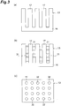
- a plurality of small fins 31 may be arranged on a side face of each plate fin 17 in order to further increase the surface area of the ammonia reservoir 13.
- the ammonia reservoir 13 may be shaped into a rectangular parallelepiped and formed with a plurality of through holes 32. This can also increase the surface area of the ammonia reservoir 13.
- ammonia reservoir 13 When ammonia is to be physically absorbed by activated carbon, it is preferred for the ammonia reservoir 13 to be kept at a desirable temperature before and after starting the absorption. When separating ammonia from activated carbon, it is preferred for the ammonia reservoir 13 to be kept at a desirable temperature before and after starting the separation.
- the fact that the ammonia reservoir 13 has a heat-exchanging structure with a large surface area makes it possible to control the temperature of the ammonia reservoir 13 by utilizing the running wind occurring when the vehicle is running. Specifically, each plate fin 17 exchanges heat with air introduced by the running wind, whereby the ammonia reservoir 13 can be kept at a desirable temperature.
- a compressed air supply portion 19 Arranged on the upstream side of the DOC 4 in the exhaust passage 3 is a compressed air supply portion 19 for ejecting compressed air used in an air brake device 30 to the upstream side of the DOC 4 in the exhaust passage 3.
- the air brake device 30 is equipped with a compressor (not depicted) for supplying the compressed air.
- the compressed air supplied from the compressor is used as a braking force source in the air brake device 30. That is, the compressed air supplied from the compressor is guided to the compressed air supply portion 19 through a conduit or the like.
- the formed body 15 incorporated in the reactor 11 melting or of ammonia aimed to react with the reaction material (e.g., CaCl 2 ) contained in the formed body 15 decomposing.
- the melting temperature of the formed body 15 containing the reaction material is about 700°C, while the decomposition temperature of ammonia is about 400°C.
- the exhaust gas is cooled by the compressed air so as to have a temperature lower than 400°C.
- the temperature of the reactor 11 is lower than the decomposition temperature of ammonia. This prevents the formed body 15 from melting and ammonia from decomposing.
- the compressed air is guided to the compressed air supply portion 19 through a conduit connected to a compressor or reservoir (none depicted) with which the air brake device 30 is equipped or the like.
- a control valve (not depicted) is arranged in this conduit.
- the control valve is controlled so as to open when cooling the exhaust gas from the engine 2, whereby the compressed air is guided to the compressed air supply portion 19.
- the opening of the control valve may be controlled so as to regulate the amount of compressed air guided to the compressed air supply portion 19.
- the compressed air discharged from the air brake device 30 when releasing the brake may be guided to the compressed air supply portion 19. This case employs the compressed air that is typically discharged, whereby energy can effectively be utilized.
- the temperature of the ammonia reservoir 13 decreases.
- the heat exchange between the ammonia reservoir 13 and the running wind restrains the temperature of the ammonia reservoir 13 from decreasing. This enables the ammonia reservoir 13 to supply ammonia smoothly to the reactor 11, thereby preventing the formed body 15 from taking time to generate heat.
- the ammonia reservoir 13 having a heat-exchanging structure is arranged in the front part of the body of the vehicle S, whereby the ammonia reservoir 13 is temperature controlled so as to become at least a desirable temperature or fall within a desirable temperature range by the air introduced by the running wind occurring when the vehicle S is running. Since the temperature of the ammonia reservoir 13 is thus controlled, no heater is necessary for heating the ammonia reservoir 13, and no power is required for operating the heater. This can inhibit energy loss from occurring due to the power for operating the heater.
- the ammonia reservoir 13 can be temperature controlled by a simple structure.
- a liquid such as water is used as a medium for a chemical reaction
- a reservoir and a reactor cannot be arranged far apart from each other.
- the reservoir and reactor are integrated with each other.
- the ammonia reservoir 13 and reactor 11 can be arranged with a distance of 1 m or more therebetween. Hence, regardless of where the reactor 11 is arranged, the plate fins 17 of the ammonia reservoir 13 can be arranged at positions where sufficient running wind acts, so as to control the temperature of the ammonia reservoir 13.
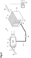
- Fig. 4 is a structural diagram illustrating the heat storage device in accordance with a modified example of the embodiment.
- the heat storage device 10 of this embodiment further comprises a compressed air outlet portion 20.
- the compressed air outlet portion 20 ejects compressed air for the temperature control of the ammonia reservoir 13 to the ammonia reservoir 13.
- the ammonia reservoir 13 is arranged adjacent to the compressed air outlet portion 20.
- the compressed air outlet portion 20 ejects the compressed air used for the air brake device 30.
- the compressed air is guided from the air brake device 30 to the compressed air outlet portion 20 through a conduit or the like. This makes it unnecessary to separately add a device for generating the compressed air.
- the compressed air aggressively blows on the ammonia reservoir 13, thereby exchanging heat with the ammonia reservoir 13. This makes it possible to keep the ammonia reservoir 13 at a desirable temperature or higher.
- the compressed air is ejected from the compressed air outlet portion 20 to the ammonia reservoir 13. Therefore, as in the above-mentioned embodiment, the temperature of the ammonia reservoir 13 can be controlled without using power for operating a heater.
- the compressed air is guided to the compressed air outlet portion 20 through a conduit connected to a compressor or reservoir (none depicted) with which the air brake device 30 is equipped or the like.
- a control valve (not depicted) is arranged in this conduit.
- the control valve is controlled so as to open when controlling the temperature of the ammonia reservoir 13, whereby the compressed air is guided to the compressed air outlet portion 20.
- the opening of the control valve may be controlled so as to regulate the amount of compressed air guided to the compressed air outlet portion 20.
- the compressed air guided from the air brake device 30 the compressed air discharged from the air brake device 30 when releasing the brake may be guided to the compressed air outlet portion 20. This case employs the compressed air that is typically discharged, whereby energy can effectively be utilized.
- the ammonia reservoir 13 can be arranged where the running wind of the vehicle S is hard to act. While the engine of the vehicle S is driven, the ammonia reservoir 13 can be temperature controlled even when the vehicle S is stopped and thus generates no running wind. Since the ammonia reservoir 13 is arranged at a location where an airflow occurs even when the vehicle is not running, there is no need to newly provide a device for the temperature control of the ammonia reservoir 13.
- Fig. 5 is a schematic structural diagram illustrating an exhaust purification system equipped with the heat storage device in accordance with another modified example of the embodiment.
- the ammonia reservoir 13 is arranged in an engine room E of the vehicle S.
- a fan 33 for sending winds to a radiator is arranged in the engine room E.
- Employed as the fan 33 is one consuming less power than a heater.
- the ammonia reservoir 13 is arranged adjacent to and on the downstream side of the fan 33. In this case, a part of the air (external heating medium) sent from the fan 33 to the radiator exchanges heat with the ammonia reservoir 13, whereby the ammonia reservoir 13 can be kept at a desirable temperature or higher. Since the ammonia reservoir 13 is arranged at a location where an airflow occurs even when the vehicle is not running, there is no need to newly provide a device for the temperature control of the ammonia reservoir 13.
- the ammonia reservoir 13 may be arranged near a flow path through which a coolant flows in the engine room E. In this case, the coolant exchanges heat with the ammonia reservoir 13, whereby the ammonia reservoir 13 can be kept at a desirable temperature or higher.
- a rear cargo room N of the vehicle S has ample space. Therefore, a fan may be arranged separately in the rear cargo room N, and the ammonia reservoir 13 may be arranged on the downstream side of this fan.
- a coolant (external heating medium) may be caused to flow through the inside of the rear cargo room N, and the ammonia reservoir 13 may be arranged near a flow path through which the coolant flows.
- the present invention is not limited to the above-mentioned embodiments.
- the reactor 11 in the heat storage device 10 is not limited to the one provided at the outer peripheral portion of the DOC 4 as in the above-mentioned embodiments.
- a reactor having a formed body chemically reacting with ammonia may be arranged on the upstream side of the DOC 4 in the exhaust passage 3.
- the present invention can be utilized in a heat storage device which warms up a catalyst arranged in an exhaust system of an internal-combustion engine (e.g., diesel engine).
- an internal-combustion engine e.g., diesel engine
Landscapes
- Engineering & Computer Science (AREA)
- Chemical & Material Sciences (AREA)
- Chemical Kinetics & Catalysis (AREA)
- Mechanical Engineering (AREA)
- General Engineering & Computer Science (AREA)
- Thermal Sciences (AREA)
- Physics & Mathematics (AREA)
- Combustion & Propulsion (AREA)
- Toxicology (AREA)
- Health & Medical Sciences (AREA)
- Materials Engineering (AREA)
- General Chemical & Material Sciences (AREA)
- Organic Chemistry (AREA)
- Exhaust Gas After Treatment (AREA)
Claims (5)
- Wärmespeichervorrichtung (10) zum Heizen eines Katalysators (4), der in einem Abgassystem einer Brennkraftmaschine (2) eines Fahrzeugs (S) angeordnet ist, wobei die Wärmespeichervorrichtung (10) Folgendes aufweist:einen Reaktor (11), der in dem Abgassystem angeordnet ist, mit einem geformten Körper (15), der mit Ammoniak chemisch reagiert und Wärme erzeugt; undeinen Ammoniakvorratsbehälter (13), der mit dem Reaktor (11) verbunden ist, zum Speichern des Ammoniaks;dadurch gekennzeichnet, dassin dem Ammoniakvorratsbehälter (13) ein Absorptionsmittel eingearbeitet ist, das das Ammoniak physikalisch absorbiert; undder Ammoniakvorratsbehälter (13) einen wärmeübertragenden Aufbau (17) hat und dessen Temperatur durch Wärmeübertragung mit einer Luft gesteuert wird.
- Wärmespeichervorrichtung (10) gemäß Anspruch 1, wobei
der Ammoniakvorratsbehälter (13) in einem von einem Vorderteil eines Körpers, einem Maschinenraum (E) und einem Heckladeraum (N) in dem Fahrzeug (S) angeordnet ist. - Wärmespeichervorrichtung (10) gemäß Anspruch 2, wobei
der Ammoniakvorratsbehälter (13) benachbart zu und an der stromabwärtigen Seite eines Lüfters (33) angeordnet ist, der in dem Maschinenraum (E) angeordnet ist. - Wärmespeichervorrichtung (10) gemäß Anspruch 2 oder 3, wobei der Ammoniakvorratsbehälter (13) benachbart zu einem Auslassabschnitt für verdichtete Luft (20) angeordnet ist, die für eine Druckluftbremsvorrichtung (30) des Fahrzeugs (S) verwendet wird.
- Wärmespeichervorrichtung (10) gemäß Anspruch 2, wobei
der Ammoniakvorratsbehälter (13) benachbart zu und an der stromabwärtigen Seite eines Lüfters (33) angeordnet ist, der in dem Heckladeraum (N) angeordnet ist.
Applications Claiming Priority (2)
| Application Number | Priority Date | Filing Date | Title |
|---|---|---|---|
| JP2012114286A JP5494722B2 (ja) | 2012-05-18 | 2012-05-18 | 蓄熱装置 |
| PCT/JP2013/063690 WO2013172422A1 (ja) | 2012-05-18 | 2013-05-16 | 蓄熱装置 |
Publications (3)
| Publication Number | Publication Date |
|---|---|
| EP2857784A1 EP2857784A1 (de) | 2015-04-08 |
| EP2857784A4 EP2857784A4 (de) | 2016-03-02 |
| EP2857784B1 true EP2857784B1 (de) | 2017-07-12 |
Family
ID=49583823
Family Applications (1)
| Application Number | Title | Priority Date | Filing Date |
|---|---|---|---|
| EP13791146.7A Not-in-force EP2857784B1 (de) | 2012-05-18 | 2013-05-16 | Wärmespeichervorrichtung |
Country Status (5)
| Country | Link |
|---|---|
| US (1) | US9316135B2 (de) |
| EP (1) | EP2857784B1 (de) |
| JP (1) | JP5494722B2 (de) |
| CN (1) | CN104303005B (de) |
| WO (1) | WO2013172422A1 (de) |
Families Citing this family (8)
| Publication number | Priority date | Publication date | Assignee | Title |
|---|---|---|---|---|
| JP6085972B2 (ja) * | 2013-01-15 | 2017-03-01 | 富士電機株式会社 | 蓄熱装置及び収容庫 |
| JP2015169413A (ja) * | 2014-03-10 | 2015-09-28 | 株式会社豊田自動織機 | 化学蓄熱装置 |
| JP2015183635A (ja) * | 2014-03-25 | 2015-10-22 | 株式会社豊田自動織機 | 化学蓄熱装置 |
| JP2015197282A (ja) * | 2014-04-03 | 2015-11-09 | 株式会社豊田自動織機 | 化学蓄熱装置 |
| JP2016020775A (ja) * | 2014-07-15 | 2016-02-04 | 株式会社豊田自動織機 | 化学蓄熱装置 |
| JP6187414B2 (ja) * | 2014-08-19 | 2017-08-30 | 株式会社豊田自動織機 | 化学蓄熱装置 |
| JP6520420B2 (ja) * | 2015-06-04 | 2019-05-29 | 株式会社豊田自動織機 | 化学蓄熱装置 |
| CN109470070A (zh) * | 2017-09-08 | 2019-03-15 | 东南大学 | 一种Lewis酸碱加合物饱和溶液的制备和分解工艺及其应用 |
Family Cites Families (12)
| Publication number | Priority date | Publication date | Assignee | Title |
|---|---|---|---|---|
| US4991644A (en) * | 1989-07-12 | 1991-02-12 | Tufts University | Engine preheating process and system |
| JPH04347320A (ja) * | 1991-05-21 | 1992-12-02 | Toyota Motor Corp | 触媒加熱装置 |
| JPH05125929A (ja) * | 1991-10-30 | 1993-05-21 | Mitsubishi Motors Corp | 触媒の早期活性化装置 |
| JPH07180539A (ja) * | 1993-12-24 | 1995-07-18 | Mitsubishi Electric Corp | 化学発熱装置 |
| JP3962252B2 (ja) * | 2001-12-27 | 2007-08-22 | アイシン精機株式会社 | 燃料電池システム |
| US20050247050A1 (en) * | 2004-05-05 | 2005-11-10 | Eaton Corporation | Adsorption based ammonia storage and regeneration system |
| JP5070760B2 (ja) | 2006-08-09 | 2012-11-14 | トヨタ自動車株式会社 | 燃料電池システム |
| JP4733619B2 (ja) | 2006-11-21 | 2011-07-27 | カルソニックカンセイ株式会社 | 車両用蓄熱システム |
| JP5211357B2 (ja) * | 2008-03-10 | 2013-06-12 | 国立大学法人広島大学 | 水素吸蔵ステーション、水素供給ステーションおよび複合カートリッジ |
| JP5402555B2 (ja) | 2009-11-18 | 2014-01-29 | アイシン精機株式会社 | 触媒暖機装置および触媒暖機装置を備えた触媒暖機システム |
| JP5381861B2 (ja) * | 2010-03-29 | 2014-01-08 | 株式会社デンソー | 化学蓄熱装置 |
| DE102010031852A1 (de) * | 2010-07-22 | 2012-01-26 | J. Eberspächer GmbH & Co. KG | Abgasanlage mit reaktivem Heizsystem |
-
2012
- 2012-05-18 JP JP2012114286A patent/JP5494722B2/ja not_active Expired - Fee Related
-
2013
- 2013-05-16 WO PCT/JP2013/063690 patent/WO2013172422A1/ja not_active Ceased
- 2013-05-16 EP EP13791146.7A patent/EP2857784B1/de not_active Not-in-force
- 2013-05-16 US US14/401,313 patent/US9316135B2/en not_active Expired - Fee Related
- 2013-05-16 CN CN201380025979.1A patent/CN104303005B/zh not_active Expired - Fee Related
Also Published As
| Publication number | Publication date |
|---|---|
| US20150135688A1 (en) | 2015-05-21 |
| CN104303005A (zh) | 2015-01-21 |
| EP2857784A4 (de) | 2016-03-02 |
| US9316135B2 (en) | 2016-04-19 |
| JP5494722B2 (ja) | 2014-05-21 |
| WO2013172422A1 (ja) | 2013-11-21 |
| JP2013242053A (ja) | 2013-12-05 |
| EP2857784A1 (de) | 2015-04-08 |
| CN104303005B (zh) | 2017-06-06 |
Similar Documents
| Publication | Publication Date | Title |
|---|---|---|
| EP2857784B1 (de) | Wärmespeichervorrichtung | |
| CN102966417B (zh) | 固体scr系统和利用该系统对固体scr还原剂加热的方法 | |
| EP2536480B1 (de) | Verfahren und vorrichtung zur steuerung einer effizienten wärmeübertragung in einem feststoff-ammoniak-speichersystem | |
| JP6622967B2 (ja) | ディーゼルエンジン排気ガスの浄化方法 | |
| JP5835030B2 (ja) | 蓄熱装置 | |
| CN104847459A (zh) | 内燃机 | |
| CN107035476A (zh) | 氨气在废气系统中的生成和输送 | |
| EP2913615A1 (de) | Wärmespeichervorrichtung | |
| CN108350787B (zh) | 具有还原剂喷射模块的冷却装置的选择性发动机冷却系统 | |
| US9476336B2 (en) | Container having a heating device for a tank for storing a liquid additive and motor vehicle having a tank | |
| JP5239719B2 (ja) | 車両用蓄熱装置 | |
| KR102776204B1 (ko) | 인젝터 냉각용 보조탱크 및 상기 보조탱크를 포함하는 작업차량 | |
| JP6493338B2 (ja) | 化学蓄熱装置 | |
| JP2005105913A (ja) | エンジンの排気浄化装置 | |
| JP6015579B2 (ja) | 蓄熱装置 | |
| KR20160107225A (ko) | 환원제 분사 모듈의 냉각 장치 및 이를 갖는 선택적 촉매 환원 시스템 | |
| JP2015004457A (ja) | 化学蓄熱装置 | |
| JP2014095513A (ja) | 化学蓄熱装置 | |
| JP2011025166A (ja) | 酸化触媒及びこれを用いたエンジンの排ガス浄化装置 | |
| JP2017194043A (ja) | 化学蓄熱装置 | |
| JP6424716B2 (ja) | 化学蓄熱装置 | |
| WO2017110405A1 (ja) | 化学蓄熱装置 | |
| JP2015230132A (ja) | 熱媒体流通装置 | |
| JP2016194391A (ja) | 化学蓄熱装置 | |
| JP2017072310A (ja) | 化学蓄熱装置 |
Legal Events
| Date | Code | Title | Description |
|---|---|---|---|
| PUAI | Public reference made under article 153(3) epc to a published international application that has entered the european phase |
Free format text: ORIGINAL CODE: 0009012 |
|
| 17P | Request for examination filed |
Effective date: 20141111 |
|
| AK | Designated contracting states |
Kind code of ref document: A1 Designated state(s): AL AT BE BG CH CY CZ DE DK EE ES FI FR GB GR HR HU IE IS IT LI LT LU LV MC MK MT NL NO PL PT RO RS SE SI SK SM TR |
|
| AX | Request for extension of the european patent |
Extension state: BA ME |
|
| DAX | Request for extension of the european patent (deleted) | ||
| RA4 | Supplementary search report drawn up and despatched (corrected) |
Effective date: 20160202 |
|
| RIC1 | Information provided on ipc code assigned before grant |
Ipc: F28D 1/02 20060101ALI20160127BHEP Ipc: F28D 20/00 20060101AFI20160127BHEP Ipc: F01N 3/24 20060101ALI20160127BHEP Ipc: C09K 5/16 20060101ALI20160127BHEP Ipc: F01N 3/20 20060101ALI20160127BHEP Ipc: F01N 3/10 20060101ALI20160127BHEP Ipc: F28D 21/00 20060101ALI20160127BHEP Ipc: F28F 3/02 20060101ALI20160127BHEP |
|
| GRAP | Despatch of communication of intention to grant a patent |
Free format text: ORIGINAL CODE: EPIDOSNIGR1 |
|
| RIC1 | Information provided on ipc code assigned before grant |
Ipc: C09K 5/16 20060101ALI20161028BHEP Ipc: F28D 21/00 20060101ALI20161028BHEP Ipc: F28D 1/02 20060101ALI20161028BHEP Ipc: F28D 20/00 20060101AFI20161028BHEP Ipc: F01N 3/10 20060101ALI20161028BHEP Ipc: F28F 3/02 20060101ALI20161028BHEP Ipc: F01N 3/24 20060101ALI20161028BHEP Ipc: F01N 3/20 20060101ALI20161028BHEP |
|
| INTG | Intention to grant announced |
Effective date: 20161130 |
|
| GRAS | Grant fee paid |
Free format text: ORIGINAL CODE: EPIDOSNIGR3 |
|
| GRAA | (expected) grant |
Free format text: ORIGINAL CODE: 0009210 |
|
| AK | Designated contracting states |
Kind code of ref document: B1 Designated state(s): AL AT BE BG CH CY CZ DE DK EE ES FI FR GB GR HR HU IE IS IT LI LT LU LV MC MK MT NL NO PL PT RO RS SE SI SK SM TR |
|
| REG | Reference to a national code |
Ref country code: GB Ref legal event code: FG4D |
|
| REG | Reference to a national code |
Ref country code: CH Ref legal event code: EP |
|
| REG | Reference to a national code |
Ref country code: AT Ref legal event code: REF Ref document number: 908747 Country of ref document: AT Kind code of ref document: T Effective date: 20170715 |
|
| REG | Reference to a national code |
Ref country code: IE Ref legal event code: FG4D |
|
| REG | Reference to a national code |
Ref country code: DE Ref legal event code: R096 Ref document number: 602013023495 Country of ref document: DE |
|
| REG | Reference to a national code |
Ref country code: NL Ref legal event code: MP Effective date: 20170712 |
|
| REG | Reference to a national code |
Ref country code: LT Ref legal event code: MG4D |
|
| REG | Reference to a national code |
Ref country code: AT Ref legal event code: MK05 Ref document number: 908747 Country of ref document: AT Kind code of ref document: T Effective date: 20170712 |
|
| PG25 | Lapsed in a contracting state [announced via postgrant information from national office to epo] |
Ref country code: LT Free format text: LAPSE BECAUSE OF FAILURE TO SUBMIT A TRANSLATION OF THE DESCRIPTION OR TO PAY THE FEE WITHIN THE PRESCRIBED TIME-LIMIT Effective date: 20170712 Ref country code: NO Free format text: LAPSE BECAUSE OF FAILURE TO SUBMIT A TRANSLATION OF THE DESCRIPTION OR TO PAY THE FEE WITHIN THE PRESCRIBED TIME-LIMIT Effective date: 20171012 Ref country code: NL Free format text: LAPSE BECAUSE OF FAILURE TO SUBMIT A TRANSLATION OF THE DESCRIPTION OR TO PAY THE FEE WITHIN THE PRESCRIBED TIME-LIMIT Effective date: 20170712 Ref country code: AT Free format text: LAPSE BECAUSE OF FAILURE TO SUBMIT A TRANSLATION OF THE DESCRIPTION OR TO PAY THE FEE WITHIN THE PRESCRIBED TIME-LIMIT Effective date: 20170712 Ref country code: HR Free format text: LAPSE BECAUSE OF FAILURE TO SUBMIT A TRANSLATION OF THE DESCRIPTION OR TO PAY THE FEE WITHIN THE PRESCRIBED TIME-LIMIT Effective date: 20170712 Ref country code: FI Free format text: LAPSE BECAUSE OF FAILURE TO SUBMIT A TRANSLATION OF THE DESCRIPTION OR TO PAY THE FEE WITHIN THE PRESCRIBED TIME-LIMIT Effective date: 20170712 Ref country code: SE Free format text: LAPSE BECAUSE OF FAILURE TO SUBMIT A TRANSLATION OF THE DESCRIPTION OR TO PAY THE FEE WITHIN THE PRESCRIBED TIME-LIMIT Effective date: 20170712 |
|
| PG25 | Lapsed in a contracting state [announced via postgrant information from national office to epo] |
Ref country code: RS Free format text: LAPSE BECAUSE OF FAILURE TO SUBMIT A TRANSLATION OF THE DESCRIPTION OR TO PAY THE FEE WITHIN THE PRESCRIBED TIME-LIMIT Effective date: 20170712 Ref country code: ES Free format text: LAPSE BECAUSE OF FAILURE TO SUBMIT A TRANSLATION OF THE DESCRIPTION OR TO PAY THE FEE WITHIN THE PRESCRIBED TIME-LIMIT Effective date: 20170712 Ref country code: BG Free format text: LAPSE BECAUSE OF FAILURE TO SUBMIT A TRANSLATION OF THE DESCRIPTION OR TO PAY THE FEE WITHIN THE PRESCRIBED TIME-LIMIT Effective date: 20171012 Ref country code: LV Free format text: LAPSE BECAUSE OF FAILURE TO SUBMIT A TRANSLATION OF THE DESCRIPTION OR TO PAY THE FEE WITHIN THE PRESCRIBED TIME-LIMIT Effective date: 20170712 Ref country code: IS Free format text: LAPSE BECAUSE OF FAILURE TO SUBMIT A TRANSLATION OF THE DESCRIPTION OR TO PAY THE FEE WITHIN THE PRESCRIBED TIME-LIMIT Effective date: 20171112 Ref country code: PL Free format text: LAPSE BECAUSE OF FAILURE TO SUBMIT A TRANSLATION OF THE DESCRIPTION OR TO PAY THE FEE WITHIN THE PRESCRIBED TIME-LIMIT Effective date: 20170712 Ref country code: GR Free format text: LAPSE BECAUSE OF FAILURE TO SUBMIT A TRANSLATION OF THE DESCRIPTION OR TO PAY THE FEE WITHIN THE PRESCRIBED TIME-LIMIT Effective date: 20171013 |
|
| REG | Reference to a national code |
Ref country code: DE Ref legal event code: R097 Ref document number: 602013023495 Country of ref document: DE |
|
| PG25 | Lapsed in a contracting state [announced via postgrant information from national office to epo] |
Ref country code: CZ Free format text: LAPSE BECAUSE OF FAILURE TO SUBMIT A TRANSLATION OF THE DESCRIPTION OR TO PAY THE FEE WITHIN THE PRESCRIBED TIME-LIMIT Effective date: 20170712 Ref country code: RO Free format text: LAPSE BECAUSE OF FAILURE TO SUBMIT A TRANSLATION OF THE DESCRIPTION OR TO PAY THE FEE WITHIN THE PRESCRIBED TIME-LIMIT Effective date: 20170712 Ref country code: DK Free format text: LAPSE BECAUSE OF FAILURE TO SUBMIT A TRANSLATION OF THE DESCRIPTION OR TO PAY THE FEE WITHIN THE PRESCRIBED TIME-LIMIT Effective date: 20170712 |
|
| PLBE | No opposition filed within time limit |
Free format text: ORIGINAL CODE: 0009261 |
|
| STAA | Information on the status of an ep patent application or granted ep patent |
Free format text: STATUS: NO OPPOSITION FILED WITHIN TIME LIMIT |
|
| PG25 | Lapsed in a contracting state [announced via postgrant information from national office to epo] |
Ref country code: EE Free format text: LAPSE BECAUSE OF FAILURE TO SUBMIT A TRANSLATION OF THE DESCRIPTION OR TO PAY THE FEE WITHIN THE PRESCRIBED TIME-LIMIT Effective date: 20170712 Ref country code: SM Free format text: LAPSE BECAUSE OF FAILURE TO SUBMIT A TRANSLATION OF THE DESCRIPTION OR TO PAY THE FEE WITHIN THE PRESCRIBED TIME-LIMIT Effective date: 20170712 Ref country code: IT Free format text: LAPSE BECAUSE OF FAILURE TO SUBMIT A TRANSLATION OF THE DESCRIPTION OR TO PAY THE FEE WITHIN THE PRESCRIBED TIME-LIMIT Effective date: 20170712 Ref country code: SK Free format text: LAPSE BECAUSE OF FAILURE TO SUBMIT A TRANSLATION OF THE DESCRIPTION OR TO PAY THE FEE WITHIN THE PRESCRIBED TIME-LIMIT Effective date: 20170712 |
|
| 26N | No opposition filed |
Effective date: 20180413 |
|
| PG25 | Lapsed in a contracting state [announced via postgrant information from national office to epo] |
Ref country code: SI Free format text: LAPSE BECAUSE OF FAILURE TO SUBMIT A TRANSLATION OF THE DESCRIPTION OR TO PAY THE FEE WITHIN THE PRESCRIBED TIME-LIMIT Effective date: 20170712 |
|
| REG | Reference to a national code |
Ref country code: DE Ref legal event code: R119 Ref document number: 602013023495 Country of ref document: DE |
|
| REG | Reference to a national code |
Ref country code: CH Ref legal event code: PL |
|
| GBPC | Gb: european patent ceased through non-payment of renewal fee |
Effective date: 20180516 |
|
| REG | Reference to a national code |
Ref country code: BE Ref legal event code: MM Effective date: 20180531 |
|
| PG25 | Lapsed in a contracting state [announced via postgrant information from national office to epo] |
Ref country code: MC Free format text: LAPSE BECAUSE OF FAILURE TO SUBMIT A TRANSLATION OF THE DESCRIPTION OR TO PAY THE FEE WITHIN THE PRESCRIBED TIME-LIMIT Effective date: 20170712 |
|
| REG | Reference to a national code |
Ref country code: IE Ref legal event code: MM4A |
|
| PG25 | Lapsed in a contracting state [announced via postgrant information from national office to epo] |
Ref country code: LI Free format text: LAPSE BECAUSE OF NON-PAYMENT OF DUE FEES Effective date: 20180531 Ref country code: CH Free format text: LAPSE BECAUSE OF NON-PAYMENT OF DUE FEES Effective date: 20180531 |
|
| PG25 | Lapsed in a contracting state [announced via postgrant information from national office to epo] |
Ref country code: LU Free format text: LAPSE BECAUSE OF NON-PAYMENT OF DUE FEES Effective date: 20180516 |
|
| PG25 | Lapsed in a contracting state [announced via postgrant information from national office to epo] |
Ref country code: FR Free format text: LAPSE BECAUSE OF NON-PAYMENT OF DUE FEES Effective date: 20180531 Ref country code: DE Free format text: LAPSE BECAUSE OF NON-PAYMENT OF DUE FEES Effective date: 20181201 Ref country code: GB Free format text: LAPSE BECAUSE OF NON-PAYMENT OF DUE FEES Effective date: 20180516 Ref country code: IE Free format text: LAPSE BECAUSE OF NON-PAYMENT OF DUE FEES Effective date: 20180516 |
|
| PG25 | Lapsed in a contracting state [announced via postgrant information from national office to epo] |
Ref country code: BE Free format text: LAPSE BECAUSE OF NON-PAYMENT OF DUE FEES Effective date: 20180531 |
|
| PG25 | Lapsed in a contracting state [announced via postgrant information from national office to epo] |
Ref country code: MT Free format text: LAPSE BECAUSE OF NON-PAYMENT OF DUE FEES Effective date: 20180516 |
|
| PG25 | Lapsed in a contracting state [announced via postgrant information from national office to epo] |
Ref country code: TR Free format text: LAPSE BECAUSE OF FAILURE TO SUBMIT A TRANSLATION OF THE DESCRIPTION OR TO PAY THE FEE WITHIN THE PRESCRIBED TIME-LIMIT Effective date: 20170712 |
|
| PG25 | Lapsed in a contracting state [announced via postgrant information from national office to epo] |
Ref country code: PT Free format text: LAPSE BECAUSE OF FAILURE TO SUBMIT A TRANSLATION OF THE DESCRIPTION OR TO PAY THE FEE WITHIN THE PRESCRIBED TIME-LIMIT Effective date: 20170712 |
|
| PG25 | Lapsed in a contracting state [announced via postgrant information from national office to epo] |
Ref country code: MK Free format text: LAPSE BECAUSE OF NON-PAYMENT OF DUE FEES Effective date: 20170712 Ref country code: HU Free format text: LAPSE BECAUSE OF FAILURE TO SUBMIT A TRANSLATION OF THE DESCRIPTION OR TO PAY THE FEE WITHIN THE PRESCRIBED TIME-LIMIT; INVALID AB INITIO Effective date: 20130516 Ref country code: CY Free format text: LAPSE BECAUSE OF FAILURE TO SUBMIT A TRANSLATION OF THE DESCRIPTION OR TO PAY THE FEE WITHIN THE PRESCRIBED TIME-LIMIT Effective date: 20170712 |
|
| PG25 | Lapsed in a contracting state [announced via postgrant information from national office to epo] |
Ref country code: AL Free format text: LAPSE BECAUSE OF FAILURE TO SUBMIT A TRANSLATION OF THE DESCRIPTION OR TO PAY THE FEE WITHIN THE PRESCRIBED TIME-LIMIT Effective date: 20170712 |