EP2857794A1 - Dispositif de contrôle d'état de voie - Google Patents
Dispositif de contrôle d'état de voie Download PDFInfo
- Publication number
- EP2857794A1 EP2857794A1 EP13793575.5A EP13793575A EP2857794A1 EP 2857794 A1 EP2857794 A1 EP 2857794A1 EP 13793575 A EP13793575 A EP 13793575A EP 2857794 A1 EP2857794 A1 EP 2857794A1
- Authority
- EP
- European Patent Office
- Prior art keywords
- rail
- detection unit
- wheel
- acceleration
- horizontal
- Prior art date
- Legal status (The legal status is an assumption and is not a legal conclusion. Google has not performed a legal analysis and makes no representation as to the accuracy of the status listed.)
- Withdrawn
Links
- 238000012806 monitoring device Methods 0.000 title claims abstract description 26
- 238000006073 displacement reaction Methods 0.000 claims abstract description 82
- 230000001133 acceleration Effects 0.000 claims abstract description 74
- 238000001514 detection method Methods 0.000 claims abstract description 66
- 230000010354 integration Effects 0.000 claims abstract description 17
- 238000005259 measurement Methods 0.000 description 17
- 238000000034 method Methods 0.000 description 13
- 238000010586 diagram Methods 0.000 description 7
- 238000011156 evaluation Methods 0.000 description 2
- 238000012545 processing Methods 0.000 description 2
- 238000004891 communication Methods 0.000 description 1
- 238000007519 figuring Methods 0.000 description 1
- 238000012544 monitoring process Methods 0.000 description 1
- 230000010355 oscillation Effects 0.000 description 1
Images







Classifications
-
- B—PERFORMING OPERATIONS; TRANSPORTING
- B61—RAILWAYS
- B61K—AUXILIARY EQUIPMENT SPECIALLY ADAPTED FOR RAILWAYS, NOT OTHERWISE PROVIDED FOR
- B61K9/00—Railway vehicle profile gauges; Detecting or indicating overheating of components; Apparatus on locomotives or cars to indicate bad track sections; General design of track recording vehicles
- B61K9/08—Measuring installations for surveying permanent way
-
- G—PHYSICS
- G01—MEASURING; TESTING
- G01B—MEASURING LENGTH, THICKNESS OR SIMILAR LINEAR DIMENSIONS; MEASURING ANGLES; MEASURING AREAS; MEASURING IRREGULARITIES OF SURFACES OR CONTOURS
- G01B11/00—Measuring arrangements characterised by the use of optical techniques
- G01B11/14—Measuring arrangements characterised by the use of optical techniques for measuring distance or clearance between spaced objects or spaced apertures
-
- G—PHYSICS
- G01—MEASURING; TESTING
- G01B—MEASURING LENGTH, THICKNESS OR SIMILAR LINEAR DIMENSIONS; MEASURING ANGLES; MEASURING AREAS; MEASURING IRREGULARITIES OF SURFACES OR CONTOURS
- G01B11/00—Measuring arrangements characterised by the use of optical techniques
- G01B11/24—Measuring arrangements characterised by the use of optical techniques for measuring contours or curvatures
-
- G—PHYSICS
- G01—MEASURING; TESTING
- G01B—MEASURING LENGTH, THICKNESS OR SIMILAR LINEAR DIMENSIONS; MEASURING ANGLES; MEASURING AREAS; MEASURING IRREGULARITIES OF SURFACES OR CONTOURS
- G01B21/00—Measuring arrangements or details thereof, where the measuring technique is not covered by the other groups of this subclass, unspecified or not relevant
- G01B21/20—Measuring arrangements or details thereof, where the measuring technique is not covered by the other groups of this subclass, unspecified or not relevant for measuring contours or curvatures, e.g. determining profile
Definitions
- the present invention relates to a track status monitoring device that detects an amount of a horizontal-direction displacement of a rail for a railway car.
- the track status monitoring device described in Patent Document 1 calculates a vertical-direction displacement of a rail (hereinafter referred to as a "vertical irregularity"), etc. by performing a 2 nd order integration of an acceleration detected by an accelerometer that is attached to an axle box or a car body, and thereby obtains a track irregularity.
- a vertical irregularity a vertical-direction displacement of a rail
- Patent Document 1 Japanese Unexamined Patent Application Publication No. 2009-300397
- a wheel tread of a railway car may be regarded as touching a rail at all times.
- vertical-direction components of a wheel track are mostly consistent with a vertical-direction displacement of the rail (i.e. a vertical irregularity).
- the vertical irregularity can therefore be easily obtained with high enough accuracy for practical purposes by performing a 2 nd order integration of a vertical-direction acceleration of the wheel or an axle box.
- a gauge between a pair of left and right rails is slightly larger than a gauge between a pair of left and right wheel flanges; therefore, there is a minute slit between the rails and the wheel flanges.
- the pair of wheels thus moves along the rails while slightly undulating within the slit, as if to thread its way through,
- a 2 nd -order integrated value of a horizontal-direction acceleration of the wheel or the axle box is not necessarily consistent with a horizontal-direction displacement of the rail (hereinafter referred to as a "horizontal displacement").
- a horizontal displacement a horizontal-direction displacement of the rail
- the first aspect of the present invention preferably calculates the horizontal displacement easily with high enough accuracy for practical purposes.
- the present invention is a track status monitoring device that detects an amount of horizontal-direction displacement of a rail for a railway car to run, the device comprises an acceleration detection unit that is disposed on the railway car and detects at least an axle-direction acceleration among accelerations generated on a wheel of the railway car; a rail position detection unit that is disposed on the railway car and detects a value, which indicates an axle-direction position of the rail in relation to the wheel; an integration unit that calculates a value based on a 2 nd -order integrated value of the acceleration detected by the acceleration detection unit; and a subtraction unit that counterbalances an undulating component of the wheel by subtracting the value detected by the rail position detection unit from the value calculated by the integration unit, and calculates an amount of a horizontal-direction displacement of the rail.
- the undulating component of the wheel can be counterbalanced by subtracting the rail position in relation to the wheel from the value obtained by 2 nd -order integrating the acceleration.
- the influence of the slit between the rail and the wheel flange can be eliminated according to the present invention.
- a horizontal displacement can therefore be easily calculated with high enough accuracy for practical purposes.
- the “horizontal displacement” is the horizontal-direction displacement of the rail including a so-called “line alignment irregularity”.
- the “line alignment irregularity” is generally used to refer to a rail unevenness inside (at the gauge-corner side of) the rail. In the present application, the “line alignment irregularity” may be either the rail unevenness inside the rail, or a rail unevenness outside (at the field-corner side of) the rail.
- the device is a track status monitoring device to which the present invention is applied.
- the track status monitoring device is configured to detect an amount of a horizontal-direction displacement of a rail for a high-speed railway car such as the Shinkansen to run.
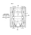
- An axle box 5 supporting an axle 3 is disposed on a truck frame 1 of a railway car as indicated in FIG. 1 .
- the axle box 5 is disposed on both left and right sides.
- the axle 3 is provided so as to extend in the direction orthogonal to a pair of left and right rails R for the railway car to run.
- a wheel 7 is disposed on both sides of the axle 3 in the axle direction.
- FIG. 1 illustrates the wheel 7 of only one side.
- the wheel 7 is provided with a wheel tread 7A and a wheel flange 7B.
- the wheel tread 7A rotates as it touches a top surface R1 of the rail R.
- the wheel flange 7B rotates as it touches the inside one (the gauge-corner side) of the rail R side surfaces.
- the axle box 5 rotatably supports the axle 3.
- the axle box 5 is arranged closer to the axle end than wheel 7.
- Each of a pair of left and right axle boxes 5 is provided with an acceleration detection unit 9 as illustrated in FIG. 2A and FIG. 2B .
- the acceleration detection unit 9 detects a vertical-direction acceleration, and an axle-direction (i.e., horizontal-direction) acceleration of axle 3.
- the acceleration detection unit 9 is provided with an accelerometer 9A that detects the vertical-direction acceleration, and an accelerometer 9B that detects the horizontal-direction acceleration.
- the axle box 5 supports the axle 3, and at the same time, the axle 3 is integrated with the wheel 7, the axle box 5 configures a rigid body part that is integrally displaced with the wheel 7.
- the acceleration detection unit 9 disposed on the axle box 5 can thus detect a vertical-direction and a horizontal-direction acceleration generated on the wheel 7.
- the acceleration detection unit 9 that is disposed on the left axle box 5 detects a vertical-direction and a horizontal-direction acceleration generated on a left wheel 7 (see FIG. 2A ).
- the acceleration detection unit 9 that is disposed on the right axle box 5 detects a vertical-direction and a horizontal-direction acceleration generated on a right wheel 7 (see FIG. 2B ).
- Each of the pair of left and right axle boxes 5 is provided with a rail position detection unit 11 that detects a position of the rail in relation to the wheel 7 in the axle-direction (a horizontal-direction) as illustrated in FIG. 1 .
- This rail position detection unit 11 is configured with a two-dimensional laser displacement gauge.
- the rail position detection unit 11 is a non-contact displacement gauge that includes a light emitting section and a light receiving section.
- the two-dimensional laser displacement gauge can measure a distance from the rail position unit 11 to an object, as well as the width of the object.
- the rail position detection unit 11 i.e., the two-dimensional laser displacement gauge
- the rail position detection unit 11 can concurrently measure a distance from the rail position detection unit 11 to the rail R, and a distance from the rail position detection unit 11 to the wheel 7 as illustrated in FIG. 3A . Consequently, the position of the rail in relation to the wheel 7 (in the axle direction (hereinafter referred to as a "rail position" in short)) can be detected.
- the rail position is detected based on a difference between a distance from the rail position detection unit 11 to a neck x of the rail R or to an external side z of the rail, and a distance from the rail position detection unit 11 to an external side surface y of the wheel 7. Therefore, when the wheel 7 moves in relation to the rail R in the axle direction as a car runs, the rail position is displaced accordingly as illustrated in FIG. 3B .
- the status of the rail R in other words, the degree of so-called “vertical-level irregularity” and “line alignment irregularity” is generally determined based on a length of versin.
- the length of versin V is defined as illustrated in FIG. 4 .
- any two points on the rail R in the longitudinal direction are named point A and point C.
- the halfway point between point A and point C is named point B.
- a 2 nd -order integrated value of the vertical-direction acceleration at each point is calculated as the amount of displacement of the rail R at the point.
- the amount of the vertical-direction displacement of the rail R is calculated with the point of reference being the point at which the vertical-direction acceleration is 0.
- the status of the rail in the horizontal direction is determined based on a horizontal-direction length of the versin.
- the horizontal-direction acceleration detected by the acceleration detection unit 9 is a value of an acceleration Ac2 that is illustrated in FIG. 5B added to an acceleration Ac1 that is illustrated in FIG. 5A .
- the acceleration Ac1 is a horizontal-direction acceleration generated on the wheel 7 by horizontal-direction displacement of the rail R.
- the acceleration Ac2 is a horizontal-direction acceleration generated on the wheel 7 by undulation of the wheel 7 in relation to the rail R.
- the status of the rail R in the horizontal direction is determined with a value, the length of versin of the horizontal-direction displacement, calculated by subtracting the length of versin based on the rail position detected by the rail position detection unit 11 from a length of versin based on the 2 nd -order integrated value of the acceleration detected by the accelerometer 9B.
- the length of versin of the horizontal-direction displacement is a length of versin indicating an amount of horizontal-direction displacement of the rail R after undulating components of the wheel 7 are counterbalanced.
- a length of versin to indicate the horizontal-direction displacement on the left rail and a length of versin to indicate the horizontal-direction displacement on the right rail are calculated.
- a displacement calculation unit 13 is provided with an integration unit 13A, a rail position calculation unit 13B, and a subtraction unit 13C.
- the integration unit 13A calculates a length of versin based on a 2 nd -order integrated value of an acceleration detected by the acceleration detection unit 9 (hereinafter referred to as a length of combined versin).
- the integration unit 13A calculates a horizontal-direction length of versin and a vertical-direction length of versin.
- an exclusive calculation circuit is provided for each length of versin to be calculated; lengths of versin are obtained by laterally actuating these calculation circuits.
- the rail position calculation unit 13B calculates a length of versin based on a position of a rail detected by the rail position detection unit 11 (hereinafter referred to as a length of relative versin).
- the length of relative versin is calculated for each of the right rail and the left rail.
- the subtraction unit 13C subtracts the length of relative versin calculated by the rail position calculation unit 13B from the horizontal-direction length of combined versin calculated by the integration unit 13A.
- the subtraction unit 13C subtracts the length of relative versin for the left rail from the length of combined versin for the left rail; and subtracts the length of relative versin for the right rail from the length of combined versin for the right rail.
- the displacement calculation unit 13 outputs at least four types of lengths of versin.
- the acceleration detection unit 9, the rail position detection unit 11, and the displacement calculation unit 13, etc. are disposed on the first or the last car in a multiple-unit (e.g., 16 cars) train.
- the horizontal-direction length of versin and a vertical-direction length of versin that are calculated by the track status monitoring device, namely the displacement calculation unit 13, are transmitted to a track maintenance center terminal and a management department terminal from a central command terminal after being transmitted to a central monitoring center via radio communication and cable line.
- the horizontal-direction acceleration detected by the acceleration detection unit 9 is a value of the horizontal-direction acceleration generated on the wheel 7 by undulation of the wheel 7 in relation to the rail R added to the horizontal-direction acceleration generated on the wheel 7 by a horizontal-direction displacement of the rail R.
- the length of versin obtained by subtracting the length of relative versin from the length of combined versin is a length of versin based on an amount of displacement obtained by subtracting the length of relative versin of the rail in relation to the wheel 7 from a combined amount of displacement in horizontal direction obtained by 2 nd order integration of the horizontal-direction acceleration.
- the undulating components of the wheel 7 can be counterbalanced by subtracting the rail position in relation to the wheel 7 from a value obtained by 2 nd -order integrating the acceleration
- the length of versin obtained by subtracting the length of relative versin from the length of combined versin indicates the horizontal-direction length of versin with the undulating components of the wheel 7 being counterbalanced.
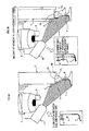
- the rail position detection unit 11 is configured with the two-dimensional laser displacement gauge; however, as illustrated in FIG. 6 , the rail position detection unit 11 may also be configured with a plurality of spot laser displacement gauges 11A to 11C that are arranged in parallel.
- the spot laser displacement gauge cannot measure a width of an object, although it can measure a distance to the object. For this reason, for example, a distance from the spot laser displacement gauge 11A to the rail R can be measured in a state illustrated in FIG. 6 ; however, when the wheel 7 moves in the horizontal direction in relation to the rail R to the state illustrated in FIG 7 , the distance to the rail R cannot be measured by the spot laser displacement gauge 11A.
- a plurality (e.g., three) of spot laser displacement gauges 11A to 11C is arranged in a given direction (e.g., vertical direction); and when it is determined that the distance to the rail R cannot be measured by the spot laser displacement gauge 11A, the distance to the rail R is then measured by the spot laser displacement gauge 11B.
- the distance to the rail R is then measured by the spot laser displacement gauge 11C.
- the position of the rail R in relation to the wheel 7 in axle direction is calculated based on the distance measured by any of the spot laser displacement gauges 11A to 11C.
- Whether the spot laser displacement gauge 11A could measure the distance to the rail R is evaluated based on whether a measurement result H 1 by the spot laser displacement gauge 11A (see FIG. 6 ) is within a preset range. In other words, when the measurement result H 1 is out of the preset range, it is thus evaluated that the spot laser displacement gauge 11 A could not measure the distance to the rail R.
- whether the spot laser displacement gauge 11B could measure the distance to the rail R is evaluated based on whether a measurement result H 2 by the spot laser displacement gauge 11B (see FIG. 7 ) is within the preset range. In other words, when the measurement result H 2 is out of the preset range, it is thus evaluated that the spot laser displacement gauge 11B could not measure the distance to the rail R.
- the above “preset range” is stored in the displacement calculation unit 13.
- the displacement calculation unit 13 evaluates whether the spot laser displacement gauge 11A or 11B could measure the distance to the rail R.
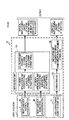
- the displacement calculation unit 13 first obtains at step S100, the measurement result H 1 measured by the spot laser displacement gauge 11A as shown in FIG. 12 ,
- the process then moves on to S110, and an evaluation takes place as to whether the measurement result H 1 is within the preset range.
- step S110 When it is determined at step S110 that the measurement result H 1 is within the preset range (S110: YES), the process then moves on to S150 and the measurement result H 1 is obtained as a value that indicates the distance to the rail R. The process is then ended.
- step S110 when it is determined at step S110 that the measurement result H 1 is out of the preset range (S110: NO), the process then moves on to S120.
- the measurement result H 2 measured by the spot laser displacement gauge 11B is obtained at step S120.
- the process then moves on to S130 and an evaluation takes place as to whether the measurement result H 2 is within the preset range.
- step S130 When it is determined at step S130 that the measurement result H 2 is within the preset range (S130: YES), the process then moves on to S150 and the measurement result H 2 is obtained as a value that indicates the distance to the rail R. The process is then ended.
- step S130 when it is determined at step S130 that the measurement result H 2 is out of the preset range (S130: NO), the process then moves on to S140.
- the measurement result H 3 measured by the spot laser displacement gauge 11C is obtained at step S140.
- the process then moves on to S150 and the measurement result H 3 is obtained as a value that indicates the distance to the rail R. The process is then ended.
- a method to determine which value to use among the values detected by the plurality of the spot laser displacement gauges 11A to 11C is however not limited to the above example; other methods may also be used for determination.
- the horizontal-direction length of versin is calculated by subtracting the length of relative versin from the length of combined versin; however, as shown in FIGs. 8A and 8B , the horizontal-direction length of versin may be calculated based on the value obtained by subtracting the position of the rail from the 2 nd -order integrated value of the horizontal-direction acceleration, without calculating the length of combined versin and the length of relative versin.
- the integration unit 13A outputs the 2 nd -order integrated value of the acceleration detected by the acceleration detection unit 9 to the subtraction unit 13C without calculating the horizontal-direction length of versin.
- the subtraction unit 13C subtracts the position of the rail from the 2 nd -order integrated value of the horizontal-direction acceleration.
- a length-of-versin calculation unit 13D then calculates the horizontal-direction length of versin based on the value obtained by subtracting the position of the rail from the 2 nd -order integrated value of the horizontal-direction acceleration.
- the horizontal-direction length of versin is outputted for each of the left rail and the right rail also in this embodiment.
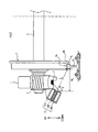
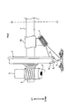
- the outside position of the rail R is detected by the rail position detection unit 11; however, the rail position may also be detected based on the inside position of the rail R as illustrated in FIG. 9 to FIG. 11 .
- the rail position detection unit 11 is coupled to an axle 3 through an attachment jig 11D.
- the rail position detection units 11 are coupled to a central beam part 1A that is provided on truck frames 1.
- the rail position detection units 11 are coupled to an attachment frame 11E that is combined with the truck frames 1.
- a counter weight 11 F is a weight that is disposed opposite the rail position detection units 11 across the central beam part 1A in the longitudinal direction of the rail R. Further in the example illustrated in FIG. 11 , the counter weight 11F suppresses generation of excessive oscillation on the attachment frame 11E during high-speed running.
- the rail position detection units 11 illustrated in FIG. 9 to FIG. 11 are configured with the two-dimensional laser displacement gauge; however, this embodiment is not limited thereto.
- the rail position detection unit 11 may be configured with a plurality of the spot laser displacement gauges 11 A to 11C, for example.
- the rail position detection unit 11 and the acceleration detection unit 9 are provided on the axle box 5; however, the present invention is not limited thereto.
- the rail position detection unit 11 and the acceleration detection unit 9 may be provided on a part other than the axle box 5, if the part is a rigid body that is displaced integrally with the wheel 7.
- rail position detection unit 11 is configured with a non-contact displacement gauge having a light emitting section and a light receiving section; however, the present invention is also not limited thereto.
- the present invention is applied to the track status monitoring device that detects the amount of the horizontal-direction displacement of the rail for a high-speed railway car to run; however, the present invention is also not limited thereto.
- the track status monitoring device monitors the state of the rail R during commercial operations; however, the present invention is also not limited thereto.
- the track status monitoring device may be combined with an exclusive car for monitoring the status of the rail R, or with an exclusive jig.
- the track status monitoring device may also be combined with a car that is not capable of self-running, and the car may be coupled to another car that is capable of self-running.
- the state of the rail R is evaluated by using the length of versin; however, the present invention is also not limited thereto.
- the state of the rail R may be evaluated, for example, just by the value obtained by subtracting the position of the rail from the 2 nd -order integrated value of the horizontal-direction acceleration.
- the acceleration detection unit 9 is provided on both of the pair of left and right axle boxes 5; however, the acceleration detection unit 9 may also be provided on only one of the pair of left and right axle boxes 5.
- the exclusive calculation circuit is provided for each length of versin to be calculated, and these calculation circuits are actuated laterally; however, the present invention is also not limited thereto.
Landscapes
- Physics & Mathematics (AREA)
- General Physics & Mathematics (AREA)
- Engineering & Computer Science (AREA)
- Mechanical Engineering (AREA)
- Machines For Laying And Maintaining Railways (AREA)
- Length Measuring Devices With Unspecified Measuring Means (AREA)
- Length Measuring Devices By Optical Means (AREA)
Applications Claiming Priority (2)
| Application Number | Priority Date | Filing Date | Title |
|---|---|---|---|
| JP2012119837A JP6096424B2 (ja) | 2012-05-25 | 2012-05-25 | 軌道状態監視装置 |
| PCT/JP2013/062212 WO2013175930A1 (fr) | 2012-05-25 | 2013-04-25 | Dispositif de contrôle d'état de voie |
Publications (2)
| Publication Number | Publication Date |
|---|---|
| EP2857794A1 true EP2857794A1 (fr) | 2015-04-08 |
| EP2857794A4 EP2857794A4 (fr) | 2016-03-23 |
Family
ID=49623629
Family Applications (1)
| Application Number | Title | Priority Date | Filing Date |
|---|---|---|---|
| EP13793575.5A Withdrawn EP2857794A4 (fr) | 2012-05-25 | 2013-04-25 | Dispositif de contrôle d'état de voie |
Country Status (9)
| Country | Link |
|---|---|
| US (1) | US9707983B2 (fr) |
| EP (1) | EP2857794A4 (fr) |
| JP (1) | JP6096424B2 (fr) |
| KR (1) | KR20150021932A (fr) |
| CN (1) | CN104321615B (fr) |
| BR (1) | BR112014028738A2 (fr) |
| HK (1) | HK1202151A1 (fr) |
| TW (1) | TW201348043A (fr) |
| WO (1) | WO2013175930A1 (fr) |
Cited By (2)
| Publication number | Priority date | Publication date | Assignee | Title |
|---|---|---|---|---|
| CN111595252A (zh) * | 2020-05-21 | 2020-08-28 | 哈尔滨市科佳通用机电股份有限公司 | 一种基于激光测量技术的车轴尺寸动态检测系统 |
| CN112284327A (zh) * | 2020-11-11 | 2021-01-29 | 余娅君 | 一种基于数据信息控制和传输的轨道检测仪及其使用方法 |
Families Citing this family (17)
| Publication number | Priority date | Publication date | Assignee | Title |
|---|---|---|---|---|
| SG11201700366UA (en) | 2014-08-07 | 2017-02-27 | Mitsubishi Electric Corp | Rail position measurement device |
| JP6644598B2 (ja) * | 2016-03-23 | 2020-02-12 | 日本製鉄株式会社 | 鉄道車両の車輪とレールとのアタック角測定方法及び装置 |
| JP6625489B2 (ja) | 2016-06-28 | 2019-12-25 | 株式会社日立ハイテクファインシステムズ | レール検査システム |
| CN106758602A (zh) * | 2016-12-05 | 2017-05-31 | 首都师范大学 | 一种轨道静态平顺性检测系统及方法 |
| US20210206406A1 (en) * | 2018-05-25 | 2021-07-08 | Kawasaki Jukogyo Kabushiki Kaisha | Wheelset rfid tag unit |
| US10543861B1 (en) | 2018-11-15 | 2020-01-28 | Focused Technology Solutions, Inc. | Vertical rail measurement device |
| WO2020121943A1 (fr) * | 2018-12-10 | 2020-06-18 | 日本製鉄株式会社 | Système d'inspection, procédé d'inspection et programme |
| JP7207148B2 (ja) * | 2019-05-14 | 2023-01-18 | 日本製鉄株式会社 | 鉄道車両用軌道の状態評価方法及び鉄道車両用台車 |
| JP7160210B2 (ja) * | 2019-08-30 | 2022-10-25 | 日本製鉄株式会社 | 処理装置、処理方法、およびプログラム |
| JP7330868B2 (ja) * | 2019-11-19 | 2023-08-22 | 大成建設株式会社 | 軌条点検装置 |
| JP7232171B2 (ja) * | 2019-12-26 | 2023-03-02 | 川崎車両株式会社 | 軌道変位計測装置、軌道変位計測システム及び軌道変位計測方法 |
| CN111824209A (zh) * | 2020-07-21 | 2020-10-27 | 深圳市迈进科技有限公司 | 一种判断道岔缺口监测终端支架松动的方法及装置 |
| CN112729181A (zh) * | 2020-12-25 | 2021-04-30 | 上海广川科技有限公司 | 一种进行晶圆定位检测的装置及方法 |
| CN112644558A (zh) * | 2021-02-05 | 2021-04-13 | 陈建明 | 一种轨道列车和轨道状态监测方法及监测系统承载平台 |
| CN113983984B (zh) * | 2021-10-28 | 2024-04-16 | 中国铁道科学研究院集团有限公司基础设施检测研究所 | 轨道检测系统所在构架的运动姿态测量方法及装置 |
| CN114330427B (zh) * | 2021-12-21 | 2024-09-06 | 中国国家铁路集团有限公司 | 轨道曲线正矢测量方法、装置、计算机设备及存储介质 |
| CN119682802B (zh) * | 2024-12-13 | 2025-07-15 | 西南交通大学 | 一种轨距测量系统、测量方法、计量校准方法 |
Family Cites Families (15)
| Publication number | Priority date | Publication date | Assignee | Title |
|---|---|---|---|---|
| US3924461A (en) * | 1974-08-20 | 1975-12-09 | Harris A Stover | Monitoring system for detecting defective rails or road beds |
| US4173073A (en) * | 1977-05-25 | 1979-11-06 | Hitachi, Ltd. | Track displacement detecting and measuring system |
| DK183089D0 (da) | 1989-04-14 | 1989-04-14 | Oedegaard & Danneskiold Samsoe | Anlaeg til sporbaseret maaling af hjulprofilen paa j ernbanehjul |
| JPH07107245B2 (ja) * | 1991-12-02 | 1995-11-15 | 日本機械保線株式会社 | 軌道状態の確認方法 |
| JPH11281330A (ja) * | 1998-03-27 | 1999-10-15 | Railway Technical Res Inst | 軌道狂いを測定する方法及びその装置 |
| JP3411861B2 (ja) * | 1999-08-30 | 2003-06-03 | 財団法人鉄道総合技術研究所 | 慣性正矢法軌道狂い検測装置 |
| JP2001270668A (ja) * | 2000-03-28 | 2001-10-02 | Mitsubishi Electric Corp | ガイドレールの据付精度測定装置及び据付精度測定方法 |
| DE10256122B4 (de) * | 2002-11-29 | 2005-06-02 | Bombardier Transportation Gmbh | Verfahren und Vorrichtung zur Ermittlung wenigstens einer Zustandsgröße einer Rad-Schiene-Paarung |
| JP2008122299A (ja) * | 2006-11-14 | 2008-05-29 | Tokyo Keisoku:Kk | レールの水平移動量計測装置 |
| JP5175630B2 (ja) | 2008-06-17 | 2013-04-03 | 東海旅客鉄道株式会社 | 軌道狂い検測装置および軌道狂い検測方法 |
| DE102009007568A1 (de) * | 2009-02-04 | 2010-08-05 | Db Netz Ag | Schienenfahrzeug mit einem durch Schienenfahrwerke auf einem Gleis verfahrbaren Maschinenrahmen |
| JP5301477B2 (ja) * | 2010-02-02 | 2013-09-25 | 公益財団法人鉄道総合技術研究所 | 慣性測定法による軌道検測装置の低速時精度補償方法及びその装置 |
| JP5453130B2 (ja) * | 2010-02-10 | 2014-03-26 | 東日本旅客鉄道株式会社 | アタック角測定装置及び測定方法 |
| CN201746752U (zh) * | 2010-08-31 | 2011-02-16 | 成都国铁精工科技有限责任公司 | 轨道检测装置 |
| JP5946272B2 (ja) * | 2011-12-28 | 2016-07-06 | 川崎重工業株式会社 | 鉄道レールの変位検出装置 |
-
2012
- 2012-05-25 JP JP2012119837A patent/JP6096424B2/ja not_active Expired - Fee Related
-
2013
- 2013-04-24 TW TW102114527A patent/TW201348043A/zh unknown
- 2013-04-25 KR KR1020147034824A patent/KR20150021932A/ko not_active Withdrawn
- 2013-04-25 EP EP13793575.5A patent/EP2857794A4/fr not_active Withdrawn
- 2013-04-25 US US14/402,433 patent/US9707983B2/en not_active Expired - Fee Related
- 2013-04-25 HK HK15102502.0A patent/HK1202151A1/xx unknown
- 2013-04-25 WO PCT/JP2013/062212 patent/WO2013175930A1/fr not_active Ceased
- 2013-04-25 CN CN201380025931.0A patent/CN104321615B/zh not_active Expired - Fee Related
- 2013-04-25 BR BR112014028738A patent/BR112014028738A2/pt not_active IP Right Cessation
Cited By (3)
| Publication number | Priority date | Publication date | Assignee | Title |
|---|---|---|---|---|
| CN111595252A (zh) * | 2020-05-21 | 2020-08-28 | 哈尔滨市科佳通用机电股份有限公司 | 一种基于激光测量技术的车轴尺寸动态检测系统 |
| CN112284327A (zh) * | 2020-11-11 | 2021-01-29 | 余娅君 | 一种基于数据信息控制和传输的轨道检测仪及其使用方法 |
| CN112284327B (zh) * | 2020-11-11 | 2021-10-01 | 黑龙江瑞兴科技股份有限公司 | 一种基于数据信息控制和传输的轨道检测仪及其使用方法 |
Also Published As
| Publication number | Publication date |
|---|---|
| HK1202151A1 (en) | 2015-09-18 |
| EP2857794A4 (fr) | 2016-03-23 |
| CN104321615A (zh) | 2015-01-28 |
| US20160114817A1 (en) | 2016-04-28 |
| KR20150021932A (ko) | 2015-03-03 |
| WO2013175930A1 (fr) | 2013-11-28 |
| CN104321615B (zh) | 2018-01-05 |
| BR112014028738A2 (pt) | 2017-06-27 |
| TW201348043A (zh) | 2013-12-01 |
| JP2013246042A (ja) | 2013-12-09 |
| US9707983B2 (en) | 2017-07-18 |
| JP6096424B2 (ja) | 2017-03-15 |
Similar Documents
| Publication | Publication Date | Title |
|---|---|---|
| EP2857794A1 (fr) | Dispositif de contrôle d'état de voie | |
| CN104169697B (zh) | 用于确定车辆的涉水深度的方法和系统 | |
| US9963157B2 (en) | Method of measuring condition of track using vehicle for commercial operation and vehicle for commercial operation for measuring condition of track | |
| JP2019105599A (ja) | タイヤ溝残量管理システム | |
| US11835422B2 (en) | Vehicle body contour-based derailment detection method for rail vehicle | |
| CN112240752B (zh) | 随车检验轨道车辆动态包络线的测试装置和测试方法 | |
| EA039076B1 (ru) | Система для измерения положения рельсового пути, расположенная на железнодорожной строительной машине | |
| CN106225691A (zh) | 车辆尺寸自动测量仪系统 | |
| JP6027480B2 (ja) | 軌道検測方法及び装置 | |
| JP6435203B2 (ja) | 脱線検知装置及び脱線検知方法 | |
| US20100026291A1 (en) | Method and device for measuring the pole orientation angle of a magnetic levitation vehicle on a magnetic levitation track | |
| JP5749496B2 (ja) | 鉄道車両アタック角測定装置および方法 | |
| CN101900600A (zh) | 轴重测量装置以及轴重测量方法 | |
| EP3486136A1 (fr) | Dispositif de mesure et procédé de mesure | |
| CN108086068B (zh) | 一种轨道几何参数单弦测量系统及其相应的测量方法 | |
| JP5426949B2 (ja) | レール下隙間測定装置 | |
| JP2018086876A (ja) | 乗り心地測定方法及び装置 | |
| CN115158412A (zh) | 铁路货车运行品质在线检测方法、装置、电子设备及介质 | |
| JP2020185876A (ja) | 鉄道車両用軌道の状態評価方法及び鉄道車両用台車 | |
| JP2019038538A (ja) | 脱線検知装置及び脱線検知方法 | |
| KR20210059124A (ko) | 객차 중량 측정장치 | |
| RU85907U1 (ru) | Устройство для измерения параметров рельсовой колеи железнодорожного пути | |
| TWI685436B (zh) | 測量軌道平整狀態的系統及方法 | |
| RU134638U1 (ru) | Бортовая измерительная система для измерения веса груза и контроля загрузки транспортного средства | |
| CN206496735U (zh) | 车辆尺寸自动测量仪 |
Legal Events
| Date | Code | Title | Description |
|---|---|---|---|
| PUAI | Public reference made under article 153(3) epc to a published international application that has entered the european phase |
Free format text: ORIGINAL CODE: 0009012 |
|
| 17P | Request for examination filed |
Effective date: 20141217 |
|
| AK | Designated contracting states |
Kind code of ref document: A1 Designated state(s): AL AT BE BG CH CY CZ DE DK EE ES FI FR GB GR HR HU IE IS IT LI LT LU LV MC MK MT NL NO PL PT RO RS SE SI SK SM TR |
|
| AX | Request for extension of the european patent |
Extension state: BA ME |
|
| DAX | Request for extension of the european patent (deleted) | ||
| RA4 | Supplementary search report drawn up and despatched (corrected) |
Effective date: 20160222 |
|
| RIC1 | Information provided on ipc code assigned before grant |
Ipc: G01B 11/14 20060101ALI20160216BHEP Ipc: B61K 9/08 20060101ALI20160216BHEP Ipc: G01B 21/20 20060101AFI20160216BHEP |
|
| STAA | Information on the status of an ep patent application or granted ep patent |
Free format text: STATUS: THE APPLICATION HAS BEEN WITHDRAWN |
|
| 18W | Application withdrawn |
Effective date: 20170324 |