EP2858070B1 - Dispositif d'évaluation de qualité de signal, procédé d'évaluation de qualité de signal et dispositif de reproduction - Google Patents
Dispositif d'évaluation de qualité de signal, procédé d'évaluation de qualité de signal et dispositif de reproduction Download PDFInfo
- Publication number
- EP2858070B1 EP2858070B1 EP13799823.3A EP13799823A EP2858070B1 EP 2858070 B1 EP2858070 B1 EP 2858070B1 EP 13799823 A EP13799823 A EP 13799823A EP 2858070 B1 EP2858070 B1 EP 2858070B1
- Authority
- EP
- European Patent Office
- Prior art keywords
- bit
- pattern
- path
- error pattern
- specific error
- Prior art date
- Legal status (The legal status is an assumption and is not a legal conclusion. Google has not performed a legal analysis and makes no representation as to the accuracy of the status listed.)
- Active
Links
Images


Classifications
-
- H—ELECTRICITY
- H03—ELECTRONIC CIRCUITRY
- H03M—CODING; DECODING; CODE CONVERSION IN GENERAL
- H03M13/00—Coding, decoding or code conversion, for error detection or error correction; Coding theory basic assumptions; Coding bounds; Error probability evaluation methods; Channel models; Simulation or testing of codes
- H03M13/37—Decoding methods or techniques, not specific to the particular type of coding provided for in groups H03M13/03 - H03M13/35
- H03M13/45—Soft decoding, i.e. using symbol reliability information
- H03M13/451—Soft decoding, i.e. using symbol reliability information using a set of candidate code words, e.g. ordered statistics decoding [OSD]
- H03M13/456—Soft decoding, i.e. using symbol reliability information using a set of candidate code words, e.g. ordered statistics decoding [OSD] wherein all the code words of the code or its dual code are tested, e.g. brute force decoding
-
- G—PHYSICS
- G11—INFORMATION STORAGE
- G11B—INFORMATION STORAGE BASED ON RELATIVE MOVEMENT BETWEEN RECORD CARRIER AND TRANSDUCER
- G11B20/00—Signal processing not specific to the method of recording or reproducing; Circuits therefor
- G11B20/10—Digital recording or reproducing
- G11B20/10009—Improvement or modification of read or write signals
- G11B20/10268—Improvement or modification of read or write signals bit detection or demodulation methods
- G11B20/10277—Improvement or modification of read or write signals bit detection or demodulation methods the demodulation process being specifically adapted to partial response channels, e.g. PRML decoding
-
- G—PHYSICS
- G11—INFORMATION STORAGE
- G11B—INFORMATION STORAGE BASED ON RELATIVE MOVEMENT BETWEEN RECORD CARRIER AND TRANSDUCER
- G11B20/00—Signal processing not specific to the method of recording or reproducing; Circuits therefor
- G11B20/10—Digital recording or reproducing
- G11B20/10009—Improvement or modification of read or write signals
- G11B20/10305—Improvement or modification of read or write signals signal quality assessment
- G11B20/10361—Improvement or modification of read or write signals signal quality assessment digital demodulation process
- G11B20/10379—Improvement or modification of read or write signals signal quality assessment digital demodulation process based on soft decisions, e.g. confidence values, probability estimates, likelihoods values or path metrics of a statistical decoding algorithm
-
- G—PHYSICS
- G11—INFORMATION STORAGE
- G11B—INFORMATION STORAGE BASED ON RELATIVE MOVEMENT BETWEEN RECORD CARRIER AND TRANSDUCER
- G11B20/00—Signal processing not specific to the method of recording or reproducing; Circuits therefor
- G11B20/10—Digital recording or reproducing
- G11B20/18—Error detection or correction; Testing, e.g. of drop-outs
- G11B20/1833—Error detection or correction; Testing, e.g. of drop-outs by adding special lists or symbols to the coded information
-
- H—ELECTRICITY
- H03—ELECTRONIC CIRCUITRY
- H03M—CODING; DECODING; CODE CONVERSION IN GENERAL
- H03M13/00—Coding, decoding or code conversion, for error detection or error correction; Coding theory basic assumptions; Coding bounds; Error probability evaluation methods; Channel models; Simulation or testing of codes
- H03M13/37—Decoding methods or techniques, not specific to the particular type of coding provided for in groups H03M13/03 - H03M13/35
- H03M13/39—Sequence estimation, i.e. using statistical methods for the reconstruction of the original codes
- H03M13/41—Sequence estimation, i.e. using statistical methods for the reconstruction of the original codes using the Viterbi algorithm or Viterbi processors
-
- H—ELECTRICITY
- H03—ELECTRONIC CIRCUITRY
- H03M—CODING; DECODING; CODE CONVERSION IN GENERAL
- H03M13/00—Coding, decoding or code conversion, for error detection or error correction; Coding theory basic assumptions; Coding bounds; Error probability evaluation methods; Channel models; Simulation or testing of codes
- H03M13/63—Joint error correction and other techniques
- H03M13/6343—Error control coding in combination with techniques for partial response channels, e.g. recording
Definitions
- the present disclosure relates to a signal quality evaluation apparatus and a signal quality evaluation method that are suitable for performing a decoding process using partial response maximum likelihood (PRML) on a reproduced signal from a recording medium, for example, and relates to a reproducing device that is provided with the signal quality evaluation apparatus and that performs reproduction of information.
- PRML partial response maximum likelihood
- CDs compact discs
- DVDs digital versatile discs
- BDs Blu-ray Discs
- a method using a technique called a partial response maximum likelihood (PRML) detection is typically used as a bit detection method.
- PRML partial response maximum likelihood
- PRML is a technology that combines a process of partial response and a technology of maximum likelihood detection.
- Partial response refers to a process of returning an output longer than one bit in response to a one-bit input, that is, a process of making a determination by a plurality of input bits of the output.
- a process of obtaining a reproduced signal as a signal obtained by multiplying an input of four consecutive information bits by 1, 2, 2, and 1 in this order and adding the results, as often used for optical disks such as the Blu-ray Disc and the like, is expressed as PR(1, 2, 2, 1).
- Maximum likelihood detection is a method of defining a distance referred to as a path metric between two signal strings, determining a distance between an actual signal and a signal predicted from an assumed bit sequence, and detecting a bit sequence providing the closest distance.
- the path metric is defined as a distance obtained by adding the squares of differences in amplitude between two signals at same times over a whole time. Viterbi detection is used to search for the bit sequence providing the closest distance.
- Partial response maximum likelihood combining these methods is a method of adjusting a signal obtained from bit information on a recording medium such that the signal is in a partial response process by a filter referred to as an equalizer, determining a path metric between the resulting reproduced signal and the partial response of an assumed bit sequence, and detecting a bit sequence providing the closest distance.
- a method using a metric difference (also referred to as a SAM value) distribution that indicates the margin of a Viterbi detector for selecting a path is already typically used as a method for evaluating the reproduced signal quality of an optical disk.
- an index value is formed by extracting several error patterns that statistically have high frequency of error occurrence, by obtaining an index value of each of the error patterns, and by integrating the obtained index values together.
- the error patterns each have a different metric difference distribution (a mean value of the distribution and a variance), the error patterns cannot be dealt as a single distribution and, thus, the above is performed.
- US 2007/0014385 A1 corresponding to patent literature 3, teaches to use a thresholding to hold the threshold well below the distribution peak of the metric differences.
- the threshold is obtained by dividing the average value by two.
- JP 2008 293577 A discloses to refer to values much lower than the medium value when assessing the quality of the reproduced signal.
- the amplitude of a short mark reproduced signal becomes extremely low such that not only the amplitude of the reproduced signal with the shortest mark, but also the amplitude of the reproduced signal with the second shortest mark can be hardly obtained.
- error patterns of the maximum likelihood decoding using PRML could be understood in units of bit or merely by a one-bit shift of the shortest mark. In other words, merely considering the above error patterns had been enough to express the signal quality.
- an object of the present disclosure is to, even if high density recording further progresses, provide a signal evaluation method that can have a strong correlation with the error rate, that is, that can have high accuracy.
- Such a technique of the present disclosure can appropriately calculate the evaluation value of the reproduced signal quality even under a high density recording condition in particular.
- the considered error patterns are only isolated errors and the length thereof are merely equivalent to or shorter than the constraint length of the maximum likelihood decoding using PRML, or the constraint length of the so-called Viterbi detection (PRML constraint length).
- PRML constraint length the constraint length of the so-called Viterbi detection
- the present disclosure has an advantageous effect in that, in the reproduced signal of the high density recording, an index value for signal evaluation that can have a strong correlation with the error rate, that is, that can have high accuracy, can be obtained.
- a reproducing device of an embodiment will be described in the following order.
- a signal quality evaluation unit 10 that is mounted on a reproducing device 1 is an example of a signal quality evaluation apparatus stipulated in the claims.
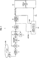
- FIG. 1 illustrates an exemplary configuration of the reproducing device 1 that is provided with the signal quality evaluation apparatus (the signal quality evaluation unit 10) according to the embodiment.
- the reproduced signal 1 in this case is configured to reproduce a signal from an optic disk 90 serving as an example of a recording medium and to obtain an index value Pq for evaluating a quality of the reproduced signal.
- the reproducing device 1 includes, for example, an optical pickup 2 that reproduces bit information of the optical disk 90, which is a removable media, and a preamplifier unit 3 that converts the signal read by the optical pickup 2 into a reproduced signal (RF signal).
- an optical pickup 2 that reproduces bit information of the optical disk 90, which is a removable media
- a preamplifier unit 3 that converts the signal read by the optical pickup 2 into a reproduced signal (RF signal).
- the reproducing device 1 includes an automatic gain control (AGC) unit 4, a waveform equalization unit 5, an A/D conversion unit 6, and a phase locked loop (PLL) unit 7 that perform processing of the reproduced signal (RF signal).
- AGC automatic gain control
- PLL phase locked loop
- the reproducing device 1 includes a partial response (PR) equalization unit 8 and a maximum likelihood decoding unit 9 to perform a PRML decoding process, as well as the signal quality evaluation unit 10 and an optical disk controller unit 15.
- PR partial response
- the playbacked optical disk 90 is, for example, a high-density disk that achieves a capacity of 33.4 GB that is BD equivalent or, further is, for example, a high-density disk that achieves a capacity of 40 GB that is BD equivalent.
- BD equivalent means that a capacity of a single recording layer becomes 40 GB under a physical condition of the Blu-ray Disk.
- the recording line density is 55.87 nm/bit for 33.4 GB and is 46.65 nm/bit for 40 GB.
- the present embodiment is configured so that an index that performs appropriate reproduced signal evaluation on the reproduced signal from the recoding medium having a recording line density of 46.65nm/bit or more can be obtained.
- the optical head unit 2 converges the laser beam to the recording layer of the optical disk 90 through an objective lens, receives the reflected light, and generates a reproduced signal (an RF signal) as an analog signal that indicates bit information readout from the optic disk 90.
- the preamplifier unit 3 amplifies the reproduced signal at a predetermined gain and outputs the amplified signal to the AGC unit 4.
- the AGC unit 4 amplifies or attenuates the amplitude of the reproduced signal from the preamplifier unit 3 on the basis of an output from the A/D conversion unit 6 and outputs the relevant signal to the waveform equalization unit 5.
- the waveform equalization unit 5 has a low pass filter (LPF) property that blocks the high frequency of the reproduced signal and a high pass filter (HPF) property that blocks the low frequency of the reproduced signal and outputs the reproduced signal to the A/D conversion unit 6 after shaping the reproduced signal waveform into one with a required property.
- LPF low pass filter
- HPF high pass filter
- Sampling is performed in the A/D conversion unit 6 on the reproduced signal that has been output from the waveform equalization unit 5 such that the reproduced signal is converted into digital data.
- the PLL unit 7 generates a reproduction clock that synchronizes with the reproduced signal on which waveform equalization has been performed, by performing a PLL processing on the basis of an output from the A/D conversion unit 6.
- the sampling in the A/D conversion unit 6 is performed at the timing when the reproduction clock is generated in the PLL circuit 7.
- the reproduction clock is also used in the PR equalization unit 8 and the maximum likelihood decoding unit 9 for PRML decoding, as well as in the signal quality evaluation unit 10 and the optical disk controller unit 15.
- PRML decoding is performed on the reproduced signal that has been converted into digitized data with the PR equalization unit 8 and the maximum likelihood decoding unit 9 such that binarized data DD, as a result of the decoding, is obtained.
- the PR equalization unit 8 equalizes channel responses to target responses such as, for example, PR(1, 2, 2, 1), PR(1, 2, 2, 2, 1). In other words, suppression of high frequency noise and intentional addition of intersymbol interference are performed on the digital reproduced signal.
- the present example assumes that high density recording of 40 GB or more that is BD equivalent is performed on an optic disk, for example.
- the PR equalization unit 8 sets the target response to PR(1, 2, 3, 3, 3, 2, 1), for example.
- the constraint length of the PRML decoding process is seven.
- the reproduced signal RF (EQ) to which an equalization process has been performed with the PR equalization unit 8 is supplied to the maximum likelihood decoding unit 9 as well as to the signal quality evaluation unit 10.
- the maximum likelihood decoding unit 9 is constituted by a Viterbi detector, for example.
- a Viterbi detector including a plurality of states formed with consecutive bits of a predetermined length as a unit and branches represented by transitions between the states is used, and is configured to detect a desired bit sequence efficiently from among all possible bit sequences.
- An actual circuit is provided with two registers, that is, a register referred to as a path metric register for each state, for storing a path metric between a partial response sequence and a signal up to the state, and a register referred to as a path memory register, for storing a flow of a bit sequence (path memory) up to the state.
- the circuit is also provided with an operation unit referred to as a branch metric unit for each branch, for calculating a path metric between a partial response sequence and a signal at the bit.
- the Viterbi detector can bring various bit sequences into one-to-one correspondence with individual paths passing through the above-described states.
- a path metric between a partial response sequence passing through these paths and an actual signal (reproduced signal) is obtained by sequentially adding together the above-mentioned branch metrics of inter-state transitions forming the paths, that is, branches.
- a path that minimizes the above-described path metric can be selected by comparing the magnitudes of path metrics of two branches or less reached in each state, and sequentially selecting a path with a smaller path metric. Information on this selection is transferred to the path memory register, whereby information representing a path reaching each state by a bit sequence is stored. The value of the path memory register ultimately converges to a bit sequence that minimizes the path metric while being updated sequentially, and the result is output.
- the binarized data DD that is obtained as a result of the decoding by the maximum likelihood decoding unit 9 is output to the optical disk controller unit 15 and the signal quality evaluation unit 10.
- the optical disk controller unit 15 demodulates the reproduction data from the optical disk 90 by performing a decoding process, an error correction process, and the like on the binarized data.
- the reproduced signal RF (EQ) on which an equalization process has been performed by the PR equalization unit 8 and the binarized data DD are input to the signal quality evaluation unit 10, and the signal quality evaluation unit 10 generates an index value Pq for evaluating the reproduced signal quality and outputs the index value Pq to the optical disk controller unit 15.
- the optical disk controller unit 15 can evaluate the reproduced signal quality with the index value Pq.
- a method of bit detection by PRML is an algorithm that compares the magnitudes of a Euclidean distance between a partial response sequence obtained from a correct bit sequence and the reproduced signal (that is, a path metric for the correct bit sequence) and a Euclidean distance between a partial response sequence obtained from an erroneous bit sequence and the reproduced signal (that is, a path metric for the erroneous bit sequence), retains a closer path, that is, a path with a smaller path metric as a more likely path, and provides a path ultimately surviving after repetition of this operation (maximum likelihood path) as a result of detection.
- a large difference between the path metrics of the two closest paths indicates that the surviving path is more likely
- a small difference between the path metrics of the two closest paths indicates that the surviving path is more unlikely, that is, there is a stronger possibility of an detection error. This will be described with reference to FIG. 2 .
- FIG. 2A and FIG. 2B are diagrams illustrating the relationships among the maximum likelihood path Pa, the second path Pb, and the actually reproduced signal (the reproduced signal RF (EQ)) on which PR equalization has been performed with the PR equalization unit 8).
- values "+3, +2, +1, 0, -1, -2, -3" on an axis of ordinates in the figures represent values of reference levels assumed in PR(1, 2, 2, 1).
- the maximum likelihood path Pa and the second path Pb shown in the figures can be considered to be the two paths for final comparison with the reproduced signal RF. That is, a path metric value for the maximum likelihood path Pa and a path metric value for the second path Pb are compared with each other, and a path with a smaller path metric value is selected as a survivor path.
- a path metric is a sum of Euclidean distances, that is, a sum of branch metrics between sampling values of the reproduced signal RF (EQ) which values are obtained in respective sampling timings indicated by black dots in FIGS. 2 and respective values obtained in corresponding timings in the maximum likelihood path Pa (or the second path Pb).
- FIG. 2A A comparison between FIG. 2A and FIG. 2B indicates that in the case of FIG. 2A , the Euclidean distance between the maximum likelihood path Pa and the reproduced signal RF (EQ) is sufficiently close, whereas the Euclidean distance between the second path Pb and the reproduced signal RF (EQ) is sufficiently far. That is, the path metric value for the maximum likelihood path Pa is sufficiently small and the path metric value for the second path Pb is sufficiently large. It is thereby possible to determine that the maximum likelihood path Pa as a detection path in this case is a more likely path.
- the Euclidean distance between the maximum likelihood path Pa and the reproduced signal RF (EQ) is increased as compared with FIG. 2A , and the Euclidean distance between the second path Pb and the reproduced signal RF (EQ) is closer. That is, in this case, the path metric value for the maximum likelihood path Pa is larger than in FIG. 2A , whereas the path metric value for the second path Pb is smaller than in FIG. 2A . Therefore the likelihood of the maximum likelihood path Pa as detection path in this case is decreased. In other words, in this case, the likelihood of the second path Pb as the other path is increased, and thus the possibility of the second path Pb being the maximum likelihood path is increased. Hence, there is a stronger possibility that the detection path as the maximum likelihood path Pa is erroneously detected in place of the path shown as the second path Pb.
- the path metric value for the maximum likelihood path Pa is sufficiently smaller than the path metric value for the second path Pb, it can be determined that more likely bit detection is performed.
- the path metric value for the maximum likelihood path Pa becomes larger and the path metric value for the second path Pb becomes smaller, it can be determined that there is a stronger possibility of the detection path as the maximum likelihood path Pa being the wrong path.
- Detection accuracy when the PRML method is employed can be estimated by a difference between the path metric value for the maximum likelihood path Pa and the path metric value for the second path Pb, that is, a metric difference.
- such a metric difference (denoted as MD) is defined as follows.
- MD ⁇ i PB i ⁇ R i 2 ⁇ ⁇ i PA i ⁇ R i 2
- PB i , PA i , and R i represent the respective values of the second path Pb, the maximum likelihood path Pa, and the reproduced signal RF in same sampling timing.
- the metric difference MD in this case is defined as a value obtained by subtracting the path metric value for the maximum likelihood path Pa from the path metric value for the second path Pb.
- the metric difference MD has a maximum value when the path metric value for the maximum likelihood path Pa in the right member of the above equation is zero, that is, when the maximum likelihood path Pa and the reproduced signal RF exactly coincide with each other. That is, this metric difference MD is information indicating that the larger the value of the metric difference MD, the higher the detection accuracy (that is, the better the signal quality).
- FIGS. 2A and 2B described above indicate that when the maximum likelihood path Pa and the reproduced signal RF exactly coincide with each other as described above, the path metric for the second path Pb is a Euclidean distance between the maximum likelihood path Pa and the second path Pb.
- the maximum value of the metric difference MD as described above is the value of the Euclidean distance between the maximum likelihood path Pa and the second path Pb.
- a minimum value of the metric difference MD is zero when the path metric value for the maximum likelihood path Pa and the path metric value for the second path Pb are a same value. That is, the minimum value of the metric difference MD is obtained when the reproduced signal RF is situated at an exact middle position between the maximum likelihood path Pa and the second path Pb in the case of FIGS. 2A and 2B . That is, the value of zero of the metric difference MD indicates that the maximum likelihood path and the second path are equally likely, and thus indicates a strongest possibility of an error.
- the metric difference MD is information indicating higher detection accuracy as the metric difference MD becomes closer to the value of the Euclidean distance between the maximum likelihood path Pa and the second path Pb (maximum value), and conversely indicating lower detection accuracy and stronger possibility of an error as the metric difference MD becomes closer to zero (minimum value).
- statistical information such for example as a variance value of values of the metric difference MD as the difference between the path metric value for the maximum likelihood path Pa and the path metric value for the second path Pb is obtained to estimate the error rate.
- difference patterns between the maximum likelihood path and the second path that can actually constitute a detection error are limited to a certain extent.
- Examples thereof include a one-bit error in which an edge of the bit sequence pattern of the second path is shifted by an amount corresponding to one bit with respect to the bit sequence pattern of the maximum likelihood path, and a two-bit error caused by disappearance of a 2T mark as a shortest mark.
- Error patterns actually appearing as an error in an early stage of use of PRML decoding for optical disk reproduction were limited substantially 100% to one-bit errors. It was therefore possible to evaluate signal quality properly by obtaining distributions of metric differences only for the one-bit error as the only error pattern.
- an index value is formed by extracting several error patterns that statistically have high frequency of error occurrence, obtaining an index value of each of the error patterns, and integrating the obtained index values together.
- the error patterns each have a different metric difference distribution (a mean value of the distribution and a variance), the error patterns cannot be dealt as a single distribution and, thus, the above is performed.
- FIG. 3 shows an example of distributions of metric differences MD for error patterns having different Euclidean distances from each other.
- an axis of ordinates indicates sample frequency
- an axis of abscissas indicates values of metric differences MD.
- FIG. 3 shows an example of distributions of metric differences MD for the three error patterns.
- a distribution denoted as MD1 in FIG. 3 is a distribution of metric differences MD for error pattern PT1 corresponding to a so-called one-bit error in which the number of different bits of the bit sequence of the maximum likelihood path Pa from those of the bit sequence of the second path Pb is one.
- a distribution denoted as MD2 is for example a distribution of metric differences MD for error pattern PT2 corresponding to a so-called two-bit error caused by a shift of a shortest mark or the like.
- a distribution denoted as MD3 is for example a distribution of metric differences MD for error pattern PT3 corresponding to a three-bit error.
- MD total a distribution denoted as "MD total” in FIG. 3 is represented by laying the three distributions MD1 to MD3 on top of each other.
- the number of different bits of the maximum likelihood path from those of the second path differs as described above, and therefore the Euclidean distance between the maximum likelihood path Pa and the second path Pb differs in error patterns PT1 to PT3.
- the Euclidean distance between the maximum likelihood path Pa and the second path Pb can be calculated by obtaining the squares of differences between values traced by the respective paths and then obtaining a sum of the squares of the differences.
- PA i and PB i be values in the maximum likelihood path Pa and the second path Pb, respectively, in same sampling timing
- an average value of each distribution is the value of the Euclidean distance d k 2 between the maximum likelihood path Pa and the second path Pb in the error pattern k. That is, assuming that a distribution of metric differences MD is thus a Gaussian distribution, the average value of the distribution should be the value of a metric difference MD at a time of best signal quality. According to the above Equation 1 for calculating the metric difference MD, the value of the Euclidean distance between the maximum likelihood path Pa and the second path Pb is the value of the metric difference MD at the time of best signal quality.
- the Euclidean distance between the maximum likelihood path Pa and the second path Pb in error pattern PT1 is represented as Euclidean distance d 1 2
- the Euclidean distance between the maximum likelihood path Pa and the second path Pb in error pattern PT2 is represented as Euclidean distance d 2 2
- the Euclidean distance between the maximum likelihood path Pa and the second path Pb in error pattern PT3 is represented as Euclidean distance d 3 2 .
- the path metric value for the maximum likelihood path Pa is equal to the path metric value for the second path Pb, as is understood from the earlier description of the metric difference MD, and hence a detection error probability is highest.
- a part where the value of the metric difference MD exceeds the part of zero (is less than zero) represents actual detection errors.
- This part cannot be observed in PRML. That is, while the value of the metric difference MD thus exceeding zero and becoming a negative value means that the path metric value for the second path Pb is smaller than the path metric value for the maximum likelihood path Pa, it is impossible that the value of the metric difference MD thus becomes a negative value because the PRML detection method detects a path having a minimum path metric value as the maximum likelihood path, as is understood from the description so far. Hence, this detection error part cannot be actually observed.
- the evaluation value is obtained on the basis of the below conception, for example.
- FIG. 4A illustrates a distribution (MDk) of a metric difference MD of a certain error pattern PTk.
- an axis of ordinates indicates sample frequency
- an axis of abscissas indicates values of metric difference MD.
- the present embodiment estimates an error rate by setting a predetermined value (Th_k) for values of metric difference MD, and determining the frequency (Fk) of occurrence of values of metric difference MD which values are less than the threshold value.
- the distribution MDk when the bit error rate bER is increased with signal quality degraded has a more extended foot comparatively as shown in FIG. 4A , for example.
- the above occurrence frequency Fk (the area of the part FK in the figure) is correspondingly increased. That is, the occurrence frequency Fk increases as the bit error rate bER is increased.
- the distribution MDk has a sharper shape as shown in FIG. 4B , for example.
- the occurrence frequency Fk is also decreased.
- the value of the occurrence frequency Fk decreases as the bit error rate bER is decreased.
- An index value that has a strong correlation with the actual bit error rates can be obtained by setting an appropriate threshold value Th_k to each of the distributions (MD1, MD2, and MD3) of the metric differences MD of the error patterns PT1, PT2, and PT3, respectively, subject to the calculation of the index value, by detecting the occurrence frequency Fk of the values of each of the metric differences MD that is below the threshold value Th_k, and by totaling the occurrence frequencies Fk, for example.
- Patent Literature 4 A method other than the above that uses the distributions of the metric differences of specific error patterns is disclosed in the above-described Patent Literature 4, for example.
- the signal quality evaluation unit 10 of the present embodiment described hereinafter can calculate the index value Pq by use of the above methods.
- FIG. 5 An exemplary configuration of the signal quality evaluation unit 10 is illustrated in FIG. 5 .
- the signal quality evaluation unit 10 includes error pattern detection units 20 (20-1, 20-2...20-n), a delay compensation unit 21, metric difference calculation units 22 (22-1, 22-2...22-n), distribution calculation units 23 (23-1, 23-2...23-n), and an index value calculation unit 24.
- Binarized data DD obtained by the PRML decoding process which performs partial response equalization with the PR equalization unit 8 and Viterbi decoding with the maximum likelihood decoding unit 9, performed on the reproduced signal of the bit information is input to each of the error pattern detection units 20, and a single or a plurality of specific error patterns that are bit patterns longer than the constraint length are detected. Then, according to the detection, detection flags Fdet are output.
- Each of the error pattern detection units 20 detects a specific error pattern.
- n pieces of error pattern detection units 20-1, 20-2...20-n are illustrated as the error pattern detection units 20, at least one or more is to be provided.
- Specific error patterns are error patterns that are considered to statistically have high error occurrence frequency in the reproduction system.
- PR(1, 2, 3, 3, 3, 2, 1) is set and the constraint length of the PRML decoding process performed in the PR equalization unit 8 and the maximum likelihood decoding unit 9 is seven.
- the specific error patterns that are detected in the error pattern detection units 20 and that are bit patterns that are longer than the constraint length are the following error patterns PTa, PTb, and PTc.
- PTa An 8-bit pattern that becomes "10111101" when the part where bit inversion occurs is expressed as "1".
- PTb A 13-bit pattern that becomes "1011110111101" when the part where bit inversion occurs is expressed as "1".
- PTc A 14-bit pattern that becomes "10111100111101" when the part where bit inversion occurs is expressed as "1".
- the part where bit inversion occurs is the part where "1" and "0" in the correct pattern and the incorrect pattern are different.
- the bit pattern is such that not only some of the "1" part is different, but all of the "1" parts are different.
- error patterns that are dominant in the error occurrence frequency are selected and the distributions thereof are used when detecting the specific error patterns and obtaining an index value.
- the number of error pattern detection units 20 may be one (only the error pattern detection unit 20-1, for example). Furthermore, when there are two dominant error patterns and when the number of specific error patterns that are used to calculate the index value is two, then, two error pattern detection units 20 (the error pattern detection units 20-1 and 20-2, for example) may be provided. In this sense, "n" is the selected number of specific error patterns.
- the metric difference calculation units 22 and the distribution calculation units 23 are each provided so as to correspond to the error pattern detection units 20, the meaning of "n" for the metric difference calculation units 22 and the distribution calculation units 23 is similar to the above.
- the three error patterns PTa, PTb, and PTc described above are assumed to be the specific error patterns, for example, and in such a case, error pattern detection units 20-1, 20-2, and 20-3 are provided.
- the error pattern detection unit 20-1 performs an operation of detecting the error pattern PTa
- the error pattern detection unit 20-2 performs an operation of detecting the error pattern PTb
- the error pattern detection unit 20-3 performs an operation of detecting the error pattern PTc.
- a single error pattern detection unit 20 includes a shift register 31, an error pattern generation unit 32, an exclusive OR operation unit 33, and a run-length-limit check unit 34.
- the shift register 31 receives an input bit stream serving as binarized data DD so that data with the same clock section as that of the specific error pattern is acquired. For example, when an 8-bit specific error pattern PTa is the target of detection, data having eight clock sections is acquired. Then, the data having the clock sections is output to the exclusive OR operation unit 33 (output XI).
- the error pattern generation unit 32 outputs a specific error pattern. For example, an 8-bit pattern of "10111101" is output to the exclusive OR operation unit 33 as the specific error pattern PTa (output X2).
- EXOR operation of the bit pattern (XI) from the shift register 31 and the specific error pattern (X2) is performed.
- bits in the bit pattern from the shift register 31 are inverted in parts where "1" exist in the "10111101” of the specific error pattern PTa.
- An operation result Y of the above is supplied to the run-length-limit check unit 34.
- the run-length-limit check unit 34 examines whether the exclusive OR operation result Y satisfies the run length limitation of the modulation code.
- the bit pattern consisting of 8 bits that has been supplied from the shift register 31 to the exclusive OR operation unit 33 and the bit pattern consisting of 8 bits in which bits are inverted in parts where "1" exist in the "10111101" of the specific error pattern PTa are related to each other as a maximum likelihood path and a second path that have a possibility of error occurrence corresponding to the specific error pattern PTa.
- the above relationship is established only when the 8-bit pattern that is the result of the exclusive OR operation satisfies the run length limitation. If the run length limitation is not satisfied, the 8-bit pattern that is the result of the exclusive OR operation cannot be an erroneously detected bit sequence from the start.
- the exclusive OR operation result satisfying the run length limitation means that an error pattern has been detected, and, in this case, a detection flag Fdet is output from the run-length-limit check unit 34.
- the shift register 31 supplies a binarized data DD having 13 clock sections to the exclusive OR operation unit 33. Furthermore, the error pattern generation unit 32 supplies a 13-bit pattern of "1011110111101" to the exclusive OR operation unit 33 as the specific error pattern PTb. Moreover, when the above exclusive OR operation result satisfies the run length restriction, a detection flag Fdet is output.
- the reproduced signal RF (EQ) that is an output of the PR equalization unit 8 of FIG. 1 is input to the delay compensation unit 21.
- the delay compensation unit 21 performs delay compensation on the reproduced signal waveform to which PR equalization has been carried out while taking into account the Viterbi detection process in the maximum likelihood decoding unit 9 and the detection processes in the error pattern detection units 20, and secures synchronization between the detection flag Fdet output from the error pattern detection units 20 and the reproduced signal RF (EQ).
- the metric difference calculation units 22 (22-1, 22-2...22-n) are provided so as to correspond to the error pattern detection units 20 (20-1, 20-2...20-n), respectively.
- Each of the metric difference calculation units 22 is supplied with a detection flag Fdet from the corresponding error pattern detection unit 20 and the reproduced signal RF (EQ) via the delay compensation unit 21.
- a metric difference associated with the reproduced signal RF (EQ) when the specific error pattern has been detected is obtained.
- each metric difference calculation unit 22 can obtain the maximum likelihood path and the second path from information of the reproduced signal RF (EQ) and that of the detection flag Fdet.
- a detection flag Fdet of the specific error pattern PTa the specific error pattern being the 8-clock section "10111101" detected in the error pattern detection unit 20-1, is supplied to the metric difference calculation unit 22-1.
- the bit streams related to ones in which all of the parts that are "1" are inverted become the maximum likelihood path and the second path.
- the distribution calculation units 23 calculate the distributions of the metric differences obtained in the metric difference calculation units 22 (22-1, 22-2...22-n), respectively. For example, the distributions described in FIGS. 3 and 4 are obtained. Accordingly, difference metric distribution that indicates the detection margin per each specific error pattern can be obtained.
- the index value calculation unit 24 calculates the overall index value Pq using the distributions of the specific error patterns obtained in the distribution calculation units 23 (23-1, 23-2...23-n) and outputs the calculated index value Pq to the optical disk controller unit 15 of FIG. 1 .
- the distribution calculation units 23 and the index value calculation unit 24 perform processes that generate the index value Pq that generates the index value of the reproduced signal quality by using the metric difference distributions obtained in the metric difference calculation units 22.
- Specific processes may be ones described in FIGS. 2 and 3 or may be a process described in Patent Literature 4, for example; various examples can be considered.
- the signal quality evaluation unit 10 of the present embodiment is configured as above.
- the specific error patterns PTa, PTb, and PTc described above are employed as the specific error patterns subject to detection.
- the optical disk 90 is assumed to be, for example, one with a recording line density of 46.65 nm/bit or more, that is, a high-density disk that achieves a capacity of 40 GB that is BD equivalent.
- the amplitude of a short mark reproduced signal becomes extremely low such that not only the amplitude of the reproduced signal with the shortest mark, but also the amplitude of the reproduced signal with the second shortest mark can be hardly obtained.
- MTF optical modulation transfer function
- Exemplified in FIG. 7 is an example of errors that have occurred when an optically simulated waveform from a line density that is equivalent to a BD of 40 GB has been detected by a PRML class PR(1, 2, 3, 3, 3, 2, 1)ML.
- the bit pattern where the errors have occurred is illustrated at the lower portion of the diagram.
- the recorded bit information in other words, the correct pattern
- the detected bit information is "00110000110001”.
- the error patterns that have been considered during conventional signal quality evaluation have been isolated errors alone and the length thereof is shorter than the constraint length of the maximum likelihood decoding using PRML, that is, the so-called constraint length of the Viterbi detection.
- the correlation between the index value using the conventional error patterns and the reproduced signal quality becomes weak.
- the value of the index value becomes a value that does not appropriately express the quality of the reproduced signal.
- the present embodiment takes into consideration the blockwise error patterns that have become dominant in the high density recording of 40 GB or more that is BD equivalent, newly performs detection of error patterns that are longer than the Viterbi constraint length, and incorporates them into the signal evaluation.
- the above-described specific error patterns PTa, PTb, and PTc are error patterns that are employed for evaluating the signal quality as patterns that are longer than the PRML constraint length.
- FIG. 8A illustrates the specific error patterns PTa, PTb, and PTc and their specific exemplary patterns.
- the lines indicated as "bit error” that are inside the thick frames correspond to the specific error patterns PTa, PTb, and PTc. In other words, they are the patterns in which the parts where bit inversions have occurred between the correct pattern and the incorrect pattern are set as "1".
- the specific error pattern PTa is "10111101", and examples of the corresponding correct pattern and incorrect pattern are "10001100” and "00110001", respectively.
- the specific error pattern PTb is "1011110111101", and examples of the corresponding correct pattern and incorrect pattern are "1000110001100” and "0011000110001", respectively.
- the specific error pattern PTc is "10111100111101", and examples of the corresponding correct pattern and incorrect pattern are "10001100001100” and "00110000110001", respectively, that is, they are the patterns illustrated in FIG. 7 .
- three error pattern detection units 20-1 to 20-3 are provided as the error pattern detection units 20-1 to 20-n of FIG. 5 . Furthermore, the three error pattern detection units 20-1 to 20-3 detect the bit patterns corresponding to the specific error patterns PTa, PTb, and PTc. Moreover, as described above, the index value is calculated from the distributions of the metric differences when the specific error patterns are detected.
- the index value Pq is not appropriate if the specific error patterns PTa, PTb, and PTc are not actually dominant error patterns.
- the specific error pattern PTa is 53.7%
- the specific error pattern PTb is 17.1%
- the specific error pattern PTc is 7.6%
- other patterns are 21.5%.
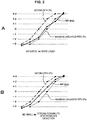
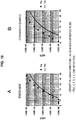
- FIGS. 9 and 10 illustrates the correlation between the signal quality evaluation value and the bit error rate under the optical simulation model.
- the axis of abscissas is the index value and the axis of ordinates is the bit error rate (bER).
- the calculated index values are plotted with black triangles and black squares.
- the solid line in the diagram indicated by TH is theoretical values of the relationship between the index value and the bit error rate when a Gaussian noise is assumed.
- FIGS. 9A and 10A correspond to the embodiment in which, together with the conventional specific error patterns that is shorter than the constraint length, all of the new specific error patterns PTa, PTb, and PTc are included and in which an evaluation value is obtained for each distribution by conducting a calculation that is similar to that illustrated in Patent Literature 4, for example.
- FIGS 9B and 10B are comparative examples in which the evaluation values are obtained by only the conventional specific error patterns.
- the error pattern PTd1 is a pattern that corresponds to a bit error that is an edge shift and the error pattern PTd2 is a pattern corresponding to bit errors that are consecutive 2T shifts.
- FIG. 9 is a case in which a detection with PR(1, 2, 2, 2, 1)ML, which is a 5-tap PRML, is performed under a line density condition of 33 GB when converted into a BD. Under the above condition, the comparative example and the embodiment coincided well with the theoretical value and both methods can be expected to have high accuracy in the index value Pq.
- a detection with PR(1, 2, 3, 3, 3, 2, 1)ML which is a 7-tap PRML, is performed under a ultra-high line density condition of 40 GB when converted into a BD, the condition greatly exceeding the conventional optical disk.
- the index value Pq is widely separated from the theoretical value and it is estimated that, due to various signal degradation factors under a real machine condition, the correlation between the index value and the error rate may vary resulting in significant degradation in the accuracy of the index.
- the index value Pq coincided with the theoretical value in a similar manner to when under the conventional optical disk condition, thus, high accuracy (correlation with the error rate) can be expected even under a real machine condition.
- the error pattern detection units 20 perform detection of specific error patterns PT1 "10111101", PT2 "1011110111101", and PT3 "10111100111101" ("1" in each pattern indicates a part where a bit inversion has occurred). Furthermore, metric differences of the specific error patterns are calculated and an index value Pq of the reproduced signal quality is generated using the distributions of the metric differences. Accordingly, an index value serving as a signal quality evaluation value with high accuracy can be obtained.
- first specific error patterns PTa, PTb, PTc, and the like
- second specific error patterns PTd1, PTd2, and the like in FIG. 11 , for example
- an "arithmetic processing system" referred to hereinafter denotes a processing system of the error pattern detection units 20, the metric difference calculation units, and the distribution calculation units 23, that is, the arithmetic processing system denotes a processing system corresponding to a single specific error pattern.
- FIG. 5 of the embodiment described above depicts that there are n numbers of arithmetic processing systems; the following are the specific examples thereof.
- the index value Pq that has a strong correlation with the bit error rate, especially in a high-density recoding equivalent to a BD of 40 GB, can be calculated.
- a PR(1, 2, 3, 3, 3, 2, 1)ML detection is given as an example; however, the configuration of the reproducing device is not limited to the above.
- the specific error patterns PTa, PTb, and PTc are dominant patterns; accordingly, even when other PR classes are employed, the technique of the present disclosure is effective.
- patterns other than the above-described specific error patterns PT1, PT2, and PT3 can be considered as specific error patterns that are longer than the constraint length.
- Specific error patterns with long sections (sections exceeding the constraint length) that correspond to blockwise errors may be selected in accordance with the PR class selected in accordance with the high density recording and the frequency characteristic.
- the technique of the present disclosure can be widely applied to decoding of bit information reproduced from a recording medium and decoding of bit information that has been transmitted.
- the recording medium is not limited to an optical disk and any recoding medium is assumed.
Landscapes
- Engineering & Computer Science (AREA)
- Signal Processing (AREA)
- Physics & Mathematics (AREA)
- Probability & Statistics with Applications (AREA)
- Theoretical Computer Science (AREA)
- Signal Processing For Digital Recording And Reproducing (AREA)
- Error Detection And Correction (AREA)
Claims (5)
- Appareil d'évaluation de qualité de signal, comprenant :une unité de détection de motif d'erreur (20-1, 20-2,... 20-n) dans laquelle sont entrées des données binarisées obtenues par l'exécution d'un processus de décodage PRML sur un signal reproduit d'informations binaires par égalisation de réponse partielle et décodage à vraisemblance maximale, l'unité de détection de motif d'erreur (20-1, 20-2,... 20-n) étant configurée pour détecter au moins un motif d'erreur spécifique qui est un motif binaire qui est plus long qu'une longueur de contrainte du processus de décodage PRML ;une unité de calcul de différence de métrique (22-1, 22-2,... 22-n) configurée pour calculer une différence de métrique dudit au moins un motif d'erreur spécifique qui a été détecté par l'unité de détection de motif d'erreur (20-1, 20-2,... 20-n) ; etune unité de génération de valeur d'index (24) configurée pour générer une valeur d'index d'une qualité du signal reproduit au moyen d'une distribution de la différence de métrique obtenue par l'unité de calcul de différence de métrique (22-1, 22-2,... 22-n), de telle façon que, lorsque la longueur de contrainte est égale à 7, au moins un motif dudit au moins un motif d'erreur spécifique est un motif de 8 bits égal à "10111101" lorsqu'une partie dans laquelle une inversion de bit se produit est exprimée par "1", oulorsque la longueur de contrainte est égale à 7, au moins un motif dudit au moins un motif d'erreur spécifique est un motif de 13 bits égal à "1011110111101" lorsqu'une partie dans laquelle une inversion de bit se produit est exprimée par "1", oulorsque la longueur de contrainte est égale à 7, au moins un motif dudit au moins un motif d'erreur spécifique est un motif de 14 bits égal à "10111100111101" lorsqu'une partie dans laquelle une inversion de bit se produit est exprimée par "1".
- Appareil d'évaluation de qualité de signal selon la revendication 1, dans lequel
lorsque ledit au moins un motif d'erreur spécifique qui est le motif de bit qui est plus long que la longueur de contrainte est un premier motif d'erreur spécifique,
l'unité de détection de motif d'erreur (20-1, 20-2,... 20-n) effectue, en plus de celle du premier motif d'erreur spécifique, la détection d'au moins un deuxième motif d'erreur spécifique qui est un motif de bit qui est plus court que la longueur de contrainte, et
l'unité de calcul de différence de métrique (22-1, 22-2,... 22-n) calcule une différence de métrique de chaque motif dudit au moins un premier motif d'erreur spécifique et dudit au moins un deuxième motif d'erreur spécifique qui ont été détectés par l'unité de détection de motif d'erreur (20-1, 20-2,... 20-n). - Appareil d'évaluation de qualité de signal selon la revendication 1, dans lequel
le signal reproduit des informations binaires est un signal qui a été reproduit depuis un support d'enregistrement sur lequel des informations binaires ont été enregistrées à une densité linéaire d'enregistrement égale ou supérieure à 44,65 nm/bit. - Procédé d'évaluation de qualité de signal, comprenant les étapes consistant à :détecter au moins un motif d'erreur spécifique qui est un motif binaire qui est plus long qu'une longueur de contrainte du processus de décodage PRML après entrée de données binarisées obtenues par l'exécution d'un processus de décodage PRML sur un signal reproduit d'informations binaires par égalisation de réponse partielle et décodage à vraisemblance maximale ;calculer une différence de métrique dudit au moins un motif d'erreur spécifique qui a été détecté ; etgénérer une valeur d'index d'une qualité du signal reproduit au moyen d'une distribution de la différence de métrique, de telle façon que,lorsque la longueur de contrainte est égale à 7, au moins un motif dudit au moins un motif d'erreur spécifique est un motif de 8 bits égal à "10111101" lorsqu'une partie dans laquelle une inversion de bit se produit est exprimée par "1", oulorsque la longueur de contrainte est égale à 7, au moins un motif dudit au moins un motif d'erreur spécifique est un motif de 13 bits égal à "1011110111101" lorsqu'une partie dans laquelle une inversion de bit se produit est exprimée par "1", oulorsque la longueur de contrainte est égale à 7, au moins un motif dudit au moins un motif d'erreur spécifique est un motif de 14 bits égal à "10111100111101" lorsqu'une partie dans laquelle une inversion de bit se produit est exprimée par "1".
- Dispositif de reproduction, comprenant :une unité de reproduction (2, 3, 4, 5, 6) configurée pour reproduire un signal reproduit d'informations binaires depuis un support d'enregistrement (90) ;une unité de décodage (8, 9) configurée pour décoder des données binarisées par l'exécution d'un processus de décodage PRML sur le signal reproduit par égalisation de réponse partielle et décodage à vraisemblance maximale ;et un appareil d'évaluation de qualité de signal selon l'une quelconque des revendications 1 à 3.
Applications Claiming Priority (2)
| Application Number | Priority Date | Filing Date | Title |
|---|---|---|---|
| JP2012126966 | 2012-06-04 | ||
| PCT/JP2013/062487 WO2013183385A1 (fr) | 2012-06-04 | 2013-04-26 | Dispositif d'évaluation de qualité de signal, procédé d'évaluation de qualité de signal et dispositif de reproduction |
Publications (3)
| Publication Number | Publication Date |
|---|---|
| EP2858070A1 EP2858070A1 (fr) | 2015-04-08 |
| EP2858070A4 EP2858070A4 (fr) | 2016-06-15 |
| EP2858070B1 true EP2858070B1 (fr) | 2019-08-14 |
Family
ID=49711786
Family Applications (1)
| Application Number | Title | Priority Date | Filing Date |
|---|---|---|---|
| EP13799823.3A Active EP2858070B1 (fr) | 2012-06-04 | 2013-04-26 | Dispositif d'évaluation de qualité de signal, procédé d'évaluation de qualité de signal et dispositif de reproduction |
Country Status (7)
| Country | Link |
|---|---|
| US (1) | US9461672B2 (fr) |
| EP (1) | EP2858070B1 (fr) |
| JP (1) | JP6090315B2 (fr) |
| KR (1) | KR102071092B1 (fr) |
| CN (1) | CN104335278B (fr) |
| TW (1) | TWI530942B (fr) |
| WO (1) | WO2013183385A1 (fr) |
Families Citing this family (2)
| Publication number | Priority date | Publication date | Assignee | Title |
|---|---|---|---|---|
| CN109643559B (zh) * | 2016-08-30 | 2020-11-27 | 索尼半导体解决方案公司 | 信号质量评估设备、信号质量评估值生成方法及再现设备 |
| EP3719802A4 (fr) | 2017-11-27 | 2021-01-06 | Sony Semiconductor Solutions Corporation | Dispositif de décodage et procédé de décodage |
Family Cites Families (15)
| Publication number | Priority date | Publication date | Assignee | Title |
|---|---|---|---|---|
| US6801061B2 (en) | 2002-08-29 | 2004-10-05 | Micron Technology, Inc. | Reduced current input buffer circuit |
| JP3857685B2 (ja) | 2003-01-28 | 2006-12-13 | 日本電気株式会社 | 信号評価方法と情報記録再生装置と情報再生装置及び情報媒体 |
| JP2005285153A (ja) * | 2004-03-26 | 2005-10-13 | Toshiba Corp | 情報記録媒体、情報再生装置、情報再生方法、および情報記録方法 |
| CN100570728C (zh) * | 2004-05-07 | 2009-12-16 | 株式会社日立制作所 | 再生信号的评价方法以及光盘装置 |
| JP4313755B2 (ja) * | 2004-05-07 | 2009-08-12 | 株式会社日立製作所 | 再生信号の評価方法および光ディスク装置 |
| JP3711140B2 (ja) | 2005-03-07 | 2005-10-26 | 株式会社東芝 | 情報記録再生装置及びその信号評価方法 |
| JP4622632B2 (ja) * | 2005-03-31 | 2011-02-02 | ソニー株式会社 | 最尤復号装置、信号評価方法、再生装置 |
| JP4750488B2 (ja) * | 2005-07-08 | 2011-08-17 | ソニー株式会社 | 評価装置、再生装置、評価方法 |
| JP4900391B2 (ja) * | 2006-09-11 | 2012-03-21 | 日本電気株式会社 | 光学的情報記録再生装置及び記録マーク品質測定方法 |
| JP5003284B2 (ja) * | 2007-05-24 | 2012-08-15 | 日本電気株式会社 | 信号品質測定装置及び情報再生装置 |
| US20080299403A1 (en) * | 2007-06-01 | 2008-12-04 | Weyerhaeuser Co. | Gas barrier packaging board |
| JPWO2009041598A1 (ja) * | 2007-09-26 | 2011-01-27 | 日本電気株式会社 | 信号品質評価装置、方法、及び、情報記録再生装置 |
| JP5391081B2 (ja) | 2008-07-01 | 2014-01-15 | パナソニック株式会社 | 再生信号評価方法、再生信号評価装置及びこれを備えた光ディスク装置 |
| JP4764932B2 (ja) * | 2009-02-03 | 2011-09-07 | 株式会社日立製作所 | 再生信号の評価方法および光ディスク装置 |
| JP2012048774A (ja) * | 2010-08-25 | 2012-03-08 | Sony Corp | 対物レンズ、レンズ製造方法、光学ドライブ装置 |
-
2013
- 2013-04-25 TW TW102114898A patent/TWI530942B/zh active
- 2013-04-26 EP EP13799823.3A patent/EP2858070B1/fr active Active
- 2013-04-26 KR KR1020147032852A patent/KR102071092B1/ko not_active Expired - Fee Related
- 2013-04-26 US US14/403,482 patent/US9461672B2/en not_active Expired - Fee Related
- 2013-04-26 CN CN201380028675.0A patent/CN104335278B/zh active Active
- 2013-04-26 WO PCT/JP2013/062487 patent/WO2013183385A1/fr not_active Ceased
- 2013-04-26 JP JP2014519884A patent/JP6090315B2/ja active Active
Non-Patent Citations (1)
| Title |
|---|
| None * |
Also Published As
| Publication number | Publication date |
|---|---|
| WO2013183385A1 (fr) | 2013-12-12 |
| TW201351402A (zh) | 2013-12-16 |
| KR20150023281A (ko) | 2015-03-05 |
| EP2858070A4 (fr) | 2016-06-15 |
| TWI530942B (zh) | 2016-04-21 |
| CN104335278A (zh) | 2015-02-04 |
| US20150143208A1 (en) | 2015-05-21 |
| KR102071092B1 (ko) | 2020-01-29 |
| JP6090315B2 (ja) | 2017-03-08 |
| JPWO2013183385A1 (ja) | 2016-01-28 |
| US9461672B2 (en) | 2016-10-04 |
| CN104335278B (zh) | 2018-04-03 |
| EP2858070A1 (fr) | 2015-04-08 |
Similar Documents
| Publication | Publication Date | Title |
|---|---|---|
| RU2497205C2 (ru) | Способ оценки сигнала воспроизведения, устройство оценки сигнала воспроизведения и устройство на оптическом диске, оснащенное таким устройством оценки сигнала воспроизведения | |
| US6934233B2 (en) | Waveform equalizer for a reproduction signal obtained by reproducing marks and non-marks recorded on a recording medium | |
| JP3668202B2 (ja) | 情報記録再生装置及びその信号評価方法 | |
| CN1917074B (zh) | 估算设备、再现设备和估算方法 | |
| JP5441906B2 (ja) | 再生信号評価方法、再生信号評価装置及びこれを備えた光ディスク装置 | |
| EP2858070B1 (fr) | Dispositif d'évaluation de qualité de signal, procédé d'évaluation de qualité de signal et dispositif de reproduction | |
| JP3711140B2 (ja) | 情報記録再生装置及びその信号評価方法 | |
| TWI638539B (zh) | Signal quality evaluation device, signal quality evaluation value generation method, and regeneration device | |
| JPWO2009041598A1 (ja) | 信号品質評価装置、方法、及び、情報記録再生装置 | |
| JP2010140551A (ja) | 光ディスク再生方法および再生装置 | |
| JP3756927B2 (ja) | 情報記録再生装置及びその信号評価方法 | |
| US20100322052A1 (en) | Reproduction signal quality evaluation device and method |
Legal Events
| Date | Code | Title | Description |
|---|---|---|---|
| PUAI | Public reference made under article 153(3) epc to a published international application that has entered the european phase |
Free format text: ORIGINAL CODE: 0009012 |
|
| 17P | Request for examination filed |
Effective date: 20141031 |
|
| AK | Designated contracting states |
Kind code of ref document: A1 Designated state(s): AL AT BE BG CH CY CZ DE DK EE ES FI FR GB GR HR HU IE IS IT LI LT LU LV MC MK MT NL NO PL PT RO RS SE SI SK SM TR |
|
| AX | Request for extension of the european patent |
Extension state: BA ME |
|
| DAX | Request for extension of the european patent (deleted) | ||
| REG | Reference to a national code |
Ref country code: DE Ref legal event code: R079 Ref document number: 602013059221 Country of ref document: DE Free format text: PREVIOUS MAIN CLASS: G11B0020180000 Ipc: G11B0020100000 |
|
| RA4 | Supplementary search report drawn up and despatched (corrected) |
Effective date: 20160517 |
|
| RIC1 | Information provided on ipc code assigned before grant |
Ipc: H03M 13/45 20060101ALI20160510BHEP Ipc: G11B 20/18 20060101ALI20160510BHEP Ipc: H03M 13/41 20060101ALI20160510BHEP Ipc: H03M 13/00 20060101ALI20160510BHEP Ipc: G11B 20/10 20060101AFI20160510BHEP |
|
| STAA | Information on the status of an ep patent application or granted ep patent |
Free format text: STATUS: EXAMINATION IS IN PROGRESS |
|
| 17Q | First examination report despatched |
Effective date: 20170103 |
|
| GRAP | Despatch of communication of intention to grant a patent |
Free format text: ORIGINAL CODE: EPIDOSNIGR1 |
|
| STAA | Information on the status of an ep patent application or granted ep patent |
Free format text: STATUS: GRANT OF PATENT IS INTENDED |
|
| INTG | Intention to grant announced |
Effective date: 20190318 |
|
| GRAS | Grant fee paid |
Free format text: ORIGINAL CODE: EPIDOSNIGR3 |
|
| GRAA | (expected) grant |
Free format text: ORIGINAL CODE: 0009210 |
|
| STAA | Information on the status of an ep patent application or granted ep patent |
Free format text: STATUS: THE PATENT HAS BEEN GRANTED |
|
| AK | Designated contracting states |
Kind code of ref document: B1 Designated state(s): AL AT BE BG CH CY CZ DE DK EE ES FI FR GB GR HR HU IE IS IT LI LT LU LV MC MK MT NL NO PL PT RO RS SE SI SK SM TR |
|
| REG | Reference to a national code |
Ref country code: GB Ref legal event code: FG4D |
|
| REG | Reference to a national code |
Ref country code: CH Ref legal event code: EP Ref country code: AT Ref legal event code: REF Ref document number: 1167976 Country of ref document: AT Kind code of ref document: T Effective date: 20190815 |
|
| REG | Reference to a national code |
Ref country code: IE Ref legal event code: FG4D |
|
| REG | Reference to a national code |
Ref country code: DE Ref legal event code: R096 Ref document number: 602013059221 Country of ref document: DE |
|
| REG | Reference to a national code |
Ref country code: NL Ref legal event code: FP |
|
| REG | Reference to a national code |
Ref country code: LT Ref legal event code: MG4D |
|
| PG25 | Lapsed in a contracting state [announced via postgrant information from national office to epo] |
Ref country code: PT Free format text: LAPSE BECAUSE OF FAILURE TO SUBMIT A TRANSLATION OF THE DESCRIPTION OR TO PAY THE FEE WITHIN THE PRESCRIBED TIME-LIMIT Effective date: 20191216 Ref country code: NO Free format text: LAPSE BECAUSE OF FAILURE TO SUBMIT A TRANSLATION OF THE DESCRIPTION OR TO PAY THE FEE WITHIN THE PRESCRIBED TIME-LIMIT Effective date: 20191114 Ref country code: BG Free format text: LAPSE BECAUSE OF FAILURE TO SUBMIT A TRANSLATION OF THE DESCRIPTION OR TO PAY THE FEE WITHIN THE PRESCRIBED TIME-LIMIT Effective date: 20191114 Ref country code: FI Free format text: LAPSE BECAUSE OF FAILURE TO SUBMIT A TRANSLATION OF THE DESCRIPTION OR TO PAY THE FEE WITHIN THE PRESCRIBED TIME-LIMIT Effective date: 20190814 Ref country code: LT Free format text: LAPSE BECAUSE OF FAILURE TO SUBMIT A TRANSLATION OF THE DESCRIPTION OR TO PAY THE FEE WITHIN THE PRESCRIBED TIME-LIMIT Effective date: 20190814 Ref country code: SE Free format text: LAPSE BECAUSE OF FAILURE TO SUBMIT A TRANSLATION OF THE DESCRIPTION OR TO PAY THE FEE WITHIN THE PRESCRIBED TIME-LIMIT Effective date: 20190814 Ref country code: HR Free format text: LAPSE BECAUSE OF FAILURE TO SUBMIT A TRANSLATION OF THE DESCRIPTION OR TO PAY THE FEE WITHIN THE PRESCRIBED TIME-LIMIT Effective date: 20190814 |
|
| REG | Reference to a national code |
Ref country code: AT Ref legal event code: MK05 Ref document number: 1167976 Country of ref document: AT Kind code of ref document: T Effective date: 20190814 |
|
| PG25 | Lapsed in a contracting state [announced via postgrant information from national office to epo] |
Ref country code: AL Free format text: LAPSE BECAUSE OF FAILURE TO SUBMIT A TRANSLATION OF THE DESCRIPTION OR TO PAY THE FEE WITHIN THE PRESCRIBED TIME-LIMIT Effective date: 20190814 Ref country code: ES Free format text: LAPSE BECAUSE OF FAILURE TO SUBMIT A TRANSLATION OF THE DESCRIPTION OR TO PAY THE FEE WITHIN THE PRESCRIBED TIME-LIMIT Effective date: 20190814 Ref country code: LV Free format text: LAPSE BECAUSE OF FAILURE TO SUBMIT A TRANSLATION OF THE DESCRIPTION OR TO PAY THE FEE WITHIN THE PRESCRIBED TIME-LIMIT Effective date: 20190814 Ref country code: IS Free format text: LAPSE BECAUSE OF FAILURE TO SUBMIT A TRANSLATION OF THE DESCRIPTION OR TO PAY THE FEE WITHIN THE PRESCRIBED TIME-LIMIT Effective date: 20191214 Ref country code: GR Free format text: LAPSE BECAUSE OF FAILURE TO SUBMIT A TRANSLATION OF THE DESCRIPTION OR TO PAY THE FEE WITHIN THE PRESCRIBED TIME-LIMIT Effective date: 20191115 Ref country code: RS Free format text: LAPSE BECAUSE OF FAILURE TO SUBMIT A TRANSLATION OF THE DESCRIPTION OR TO PAY THE FEE WITHIN THE PRESCRIBED TIME-LIMIT Effective date: 20190814 |
|
| PG25 | Lapsed in a contracting state [announced via postgrant information from national office to epo] |
Ref country code: TR Free format text: LAPSE BECAUSE OF FAILURE TO SUBMIT A TRANSLATION OF THE DESCRIPTION OR TO PAY THE FEE WITHIN THE PRESCRIBED TIME-LIMIT Effective date: 20190814 |
|
| PG25 | Lapsed in a contracting state [announced via postgrant information from national office to epo] |
Ref country code: IT Free format text: LAPSE BECAUSE OF FAILURE TO SUBMIT A TRANSLATION OF THE DESCRIPTION OR TO PAY THE FEE WITHIN THE PRESCRIBED TIME-LIMIT Effective date: 20190814 Ref country code: DK Free format text: LAPSE BECAUSE OF FAILURE TO SUBMIT A TRANSLATION OF THE DESCRIPTION OR TO PAY THE FEE WITHIN THE PRESCRIBED TIME-LIMIT Effective date: 20190814 Ref country code: PL Free format text: LAPSE BECAUSE OF FAILURE TO SUBMIT A TRANSLATION OF THE DESCRIPTION OR TO PAY THE FEE WITHIN THE PRESCRIBED TIME-LIMIT Effective date: 20190814 Ref country code: AT Free format text: LAPSE BECAUSE OF FAILURE TO SUBMIT A TRANSLATION OF THE DESCRIPTION OR TO PAY THE FEE WITHIN THE PRESCRIBED TIME-LIMIT Effective date: 20190814 Ref country code: EE Free format text: LAPSE BECAUSE OF FAILURE TO SUBMIT A TRANSLATION OF THE DESCRIPTION OR TO PAY THE FEE WITHIN THE PRESCRIBED TIME-LIMIT Effective date: 20190814 Ref country code: RO Free format text: LAPSE BECAUSE OF FAILURE TO SUBMIT A TRANSLATION OF THE DESCRIPTION OR TO PAY THE FEE WITHIN THE PRESCRIBED TIME-LIMIT Effective date: 20190814 |
|
| PG25 | Lapsed in a contracting state [announced via postgrant information from national office to epo] |
Ref country code: CZ Free format text: LAPSE BECAUSE OF FAILURE TO SUBMIT A TRANSLATION OF THE DESCRIPTION OR TO PAY THE FEE WITHIN THE PRESCRIBED TIME-LIMIT Effective date: 20190814 Ref country code: SK Free format text: LAPSE BECAUSE OF FAILURE TO SUBMIT A TRANSLATION OF THE DESCRIPTION OR TO PAY THE FEE WITHIN THE PRESCRIBED TIME-LIMIT Effective date: 20190814 Ref country code: IS Free format text: LAPSE BECAUSE OF FAILURE TO SUBMIT A TRANSLATION OF THE DESCRIPTION OR TO PAY THE FEE WITHIN THE PRESCRIBED TIME-LIMIT Effective date: 20200224 Ref country code: SM Free format text: LAPSE BECAUSE OF FAILURE TO SUBMIT A TRANSLATION OF THE DESCRIPTION OR TO PAY THE FEE WITHIN THE PRESCRIBED TIME-LIMIT Effective date: 20190814 |
|
| REG | Reference to a national code |
Ref country code: DE Ref legal event code: R097 Ref document number: 602013059221 Country of ref document: DE |
|
| PLBE | No opposition filed within time limit |
Free format text: ORIGINAL CODE: 0009261 |
|
| STAA | Information on the status of an ep patent application or granted ep patent |
Free format text: STATUS: NO OPPOSITION FILED WITHIN TIME LIMIT |
|
| PG2D | Information on lapse in contracting state deleted |
Ref country code: IS |
|
| 26N | No opposition filed |
Effective date: 20200603 |
|
| PG25 | Lapsed in a contracting state [announced via postgrant information from national office to epo] |
Ref country code: SI Free format text: LAPSE BECAUSE OF FAILURE TO SUBMIT A TRANSLATION OF THE DESCRIPTION OR TO PAY THE FEE WITHIN THE PRESCRIBED TIME-LIMIT Effective date: 20190814 |
|
| PG25 | Lapsed in a contracting state [announced via postgrant information from national office to epo] |
Ref country code: MC Free format text: LAPSE BECAUSE OF FAILURE TO SUBMIT A TRANSLATION OF THE DESCRIPTION OR TO PAY THE FEE WITHIN THE PRESCRIBED TIME-LIMIT Effective date: 20190814 |
|
| REG | Reference to a national code |
Ref country code: CH Ref legal event code: PL |
|
| PG25 | Lapsed in a contracting state [announced via postgrant information from national office to epo] |
Ref country code: LU Free format text: LAPSE BECAUSE OF NON-PAYMENT OF DUE FEES Effective date: 20200426 Ref country code: CH Free format text: LAPSE BECAUSE OF NON-PAYMENT OF DUE FEES Effective date: 20200430 Ref country code: LI Free format text: LAPSE BECAUSE OF NON-PAYMENT OF DUE FEES Effective date: 20200430 |
|
| REG | Reference to a national code |
Ref country code: BE Ref legal event code: MM Effective date: 20200430 |
|
| PG25 | Lapsed in a contracting state [announced via postgrant information from national office to epo] |
Ref country code: BE Free format text: LAPSE BECAUSE OF NON-PAYMENT OF DUE FEES Effective date: 20200430 |
|
| PG25 | Lapsed in a contracting state [announced via postgrant information from national office to epo] |
Ref country code: IE Free format text: LAPSE BECAUSE OF NON-PAYMENT OF DUE FEES Effective date: 20200426 |
|
| PG25 | Lapsed in a contracting state [announced via postgrant information from national office to epo] |
Ref country code: MT Free format text: LAPSE BECAUSE OF FAILURE TO SUBMIT A TRANSLATION OF THE DESCRIPTION OR TO PAY THE FEE WITHIN THE PRESCRIBED TIME-LIMIT Effective date: 20190814 Ref country code: CY Free format text: LAPSE BECAUSE OF FAILURE TO SUBMIT A TRANSLATION OF THE DESCRIPTION OR TO PAY THE FEE WITHIN THE PRESCRIBED TIME-LIMIT Effective date: 20190814 |
|
| PG25 | Lapsed in a contracting state [announced via postgrant information from national office to epo] |
Ref country code: MK Free format text: LAPSE BECAUSE OF FAILURE TO SUBMIT A TRANSLATION OF THE DESCRIPTION OR TO PAY THE FEE WITHIN THE PRESCRIBED TIME-LIMIT Effective date: 20190814 |
|
| PGFP | Annual fee paid to national office [announced via postgrant information from national office to epo] |
Ref country code: FR Payment date: 20230321 Year of fee payment: 11 |
|
| PGFP | Annual fee paid to national office [announced via postgrant information from national office to epo] |
Ref country code: GB Payment date: 20230322 Year of fee payment: 11 |
|
| PGFP | Annual fee paid to national office [announced via postgrant information from national office to epo] |
Ref country code: NL Payment date: 20230321 Year of fee payment: 11 |
|
| P01 | Opt-out of the competence of the unified patent court (upc) registered |
Effective date: 20230527 |
|
| PGFP | Annual fee paid to national office [announced via postgrant information from national office to epo] |
Ref country code: DE Payment date: 20230321 Year of fee payment: 11 |
|
| REG | Reference to a national code |
Ref country code: DE Ref legal event code: R119 Ref document number: 602013059221 Country of ref document: DE |
|
| REG | Reference to a national code |
Ref country code: NL Ref legal event code: MM Effective date: 20240501 |
|
| GBPC | Gb: european patent ceased through non-payment of renewal fee |
Effective date: 20240426 |
|
| PG25 | Lapsed in a contracting state [announced via postgrant information from national office to epo] |
Ref country code: DE Free format text: LAPSE BECAUSE OF NON-PAYMENT OF DUE FEES Effective date: 20241105 |
|
| PG25 | Lapsed in a contracting state [announced via postgrant information from national office to epo] |
Ref country code: NL Free format text: LAPSE BECAUSE OF NON-PAYMENT OF DUE FEES Effective date: 20240501 |
|
| PG25 | Lapsed in a contracting state [announced via postgrant information from national office to epo] |
Ref country code: GB Free format text: LAPSE BECAUSE OF NON-PAYMENT OF DUE FEES Effective date: 20240426 |
|
| PG25 | Lapsed in a contracting state [announced via postgrant information from national office to epo] |
Ref country code: FR Free format text: LAPSE BECAUSE OF NON-PAYMENT OF DUE FEES Effective date: 20240430 |
|
| PG25 | Lapsed in a contracting state [announced via postgrant information from national office to epo] |
Ref country code: NL Free format text: LAPSE BECAUSE OF NON-PAYMENT OF DUE FEES Effective date: 20240501 Ref country code: GB Free format text: LAPSE BECAUSE OF NON-PAYMENT OF DUE FEES Effective date: 20240426 Ref country code: FR Free format text: LAPSE BECAUSE OF NON-PAYMENT OF DUE FEES Effective date: 20240430 Ref country code: DE Free format text: LAPSE BECAUSE OF NON-PAYMENT OF DUE FEES Effective date: 20241105 |