WO2013183385A1 - Dispositif d'évaluation de qualité de signal, procédé d'évaluation de qualité de signal et dispositif de reproduction - Google Patents
Dispositif d'évaluation de qualité de signal, procédé d'évaluation de qualité de signal et dispositif de reproduction Download PDFInfo
- Publication number
- WO2013183385A1 WO2013183385A1 PCT/JP2013/062487 JP2013062487W WO2013183385A1 WO 2013183385 A1 WO2013183385 A1 WO 2013183385A1 JP 2013062487 W JP2013062487 W JP 2013062487W WO 2013183385 A1 WO2013183385 A1 WO 2013183385A1
- Authority
- WO
- WIPO (PCT)
- Prior art keywords
- bit
- signal quality
- pattern
- error
- error pattern
- Prior art date
- Legal status (The legal status is an assumption and is not a legal conclusion. Google has not performed a legal analysis and makes no representation as to the accuracy of the status listed.)
- Ceased
Links
Images


Classifications
-
- H—ELECTRICITY
- H03—ELECTRONIC CIRCUITRY
- H03M—CODING; DECODING; CODE CONVERSION IN GENERAL
- H03M13/00—Coding, decoding or code conversion, for error detection or error correction; Coding theory basic assumptions; Coding bounds; Error probability evaluation methods; Channel models; Simulation or testing of codes
- H03M13/37—Decoding methods or techniques, not specific to the particular type of coding provided for in groups H03M13/03 - H03M13/35
- H03M13/45—Soft decoding, i.e. using symbol reliability information
- H03M13/451—Soft decoding, i.e. using symbol reliability information using a set of candidate code words, e.g. ordered statistics decoding [OSD]
- H03M13/456—Soft decoding, i.e. using symbol reliability information using a set of candidate code words, e.g. ordered statistics decoding [OSD] wherein all the code words of the code or its dual code are tested, e.g. brute force decoding
-
- G—PHYSICS
- G11—INFORMATION STORAGE
- G11B—INFORMATION STORAGE BASED ON RELATIVE MOVEMENT BETWEEN RECORD CARRIER AND TRANSDUCER
- G11B20/00—Signal processing not specific to the method of recording or reproducing; Circuits therefor
- G11B20/10—Digital recording or reproducing
- G11B20/10009—Improvement or modification of read or write signals
- G11B20/10268—Improvement or modification of read or write signals bit detection or demodulation methods
- G11B20/10277—Improvement or modification of read or write signals bit detection or demodulation methods the demodulation process being specifically adapted to partial response channels, e.g. PRML decoding
-
- G—PHYSICS
- G11—INFORMATION STORAGE
- G11B—INFORMATION STORAGE BASED ON RELATIVE MOVEMENT BETWEEN RECORD CARRIER AND TRANSDUCER
- G11B20/00—Signal processing not specific to the method of recording or reproducing; Circuits therefor
- G11B20/10—Digital recording or reproducing
- G11B20/10009—Improvement or modification of read or write signals
- G11B20/10305—Improvement or modification of read or write signals signal quality assessment
- G11B20/10361—Improvement or modification of read or write signals signal quality assessment digital demodulation process
- G11B20/10379—Improvement or modification of read or write signals signal quality assessment digital demodulation process based on soft decisions, e.g. confidence values, probability estimates, likelihoods values or path metrics of a statistical decoding algorithm
-
- G—PHYSICS
- G11—INFORMATION STORAGE
- G11B—INFORMATION STORAGE BASED ON RELATIVE MOVEMENT BETWEEN RECORD CARRIER AND TRANSDUCER
- G11B20/00—Signal processing not specific to the method of recording or reproducing; Circuits therefor
- G11B20/10—Digital recording or reproducing
- G11B20/18—Error detection or correction; Testing, e.g. of drop-outs
- G11B20/1833—Error detection or correction; Testing, e.g. of drop-outs by adding special lists or symbols to the coded information
-
- H—ELECTRICITY
- H03—ELECTRONIC CIRCUITRY
- H03M—CODING; DECODING; CODE CONVERSION IN GENERAL
- H03M13/00—Coding, decoding or code conversion, for error detection or error correction; Coding theory basic assumptions; Coding bounds; Error probability evaluation methods; Channel models; Simulation or testing of codes
- H03M13/63—Joint error correction and other techniques
- H03M13/6343—Error control coding in combination with techniques for partial response channels, e.g. recording
-
- H—ELECTRICITY
- H03—ELECTRONIC CIRCUITRY
- H03M—CODING; DECODING; CODE CONVERSION IN GENERAL
- H03M13/00—Coding, decoding or code conversion, for error detection or error correction; Coding theory basic assumptions; Coding bounds; Error probability evaluation methods; Channel models; Simulation or testing of codes
- H03M13/37—Decoding methods or techniques, not specific to the particular type of coding provided for in groups H03M13/03 - H03M13/35
- H03M13/39—Sequence estimation, i.e. using statistical methods for the reconstruction of the original codes
- H03M13/41—Sequence estimation, i.e. using statistical methods for the reconstruction of the original codes using the Viterbi algorithm or Viterbi processors
Definitions
- the present disclosure includes a signal quality evaluation apparatus, a signal quality evaluation method, and such a signal quality evaluation apparatus, which are suitable for performing decoding processing using PRML (Partial Response Maximum Likelihood), for example, on a reproduction signal from a recording medium.
- PRML Partial Response Maximum Likelihood
- the present invention relates to a reproducing apparatus for reproducing information.
- CD Compact Disc
- DVD Digital Versatile Disc
- BD Blu-ray Disc (registered trademark)
- PRML partial response maximum likelihood
- PRML is a technique that combines the process of partial response and the technique of maximum likelihood detection.
- a partial response is a process of returning an output longer than 1 bit with respect to a 1-bit input, that is, a process of determining an output by a plurality of input bits, and is often used particularly for an optical disc such as a Blu-ray disc.
- a process in which a reproduction signal is obtained as a signal obtained by multiplying the input of continuous 4-bit information bits by sequentially multiplying them by 1, 2, 2, 1 is PR (1, 2, 2, 1 ).
- a distance called a path metric is defined between two signal sequences, and the distance between the actual signal and the signal expected from the assumed bit sequence is examined.
- the path metric is a distance defined as a distance obtained by adding the square of the amplitude difference between two signals at the same time over the entire time.
- Viterbi detection is used to search for a bit sequence that minimizes this distance.
- the partial response maximum likelihood detection combining these is a bit sequence that is assumed to be the reproduced signal obtained by adjusting the signal obtained from the bit information of the recording medium so that it becomes a partial response process by a filter called an equalizer.
- Patent Documents 1, 2, 3, and 4 disclose a signal quality evaluation method that has a good correlation with the PRML error rate even during high-density recording on a conventional optical disk.
- the PRML class that is actually used several error patterns with a statistically high error occurrence frequency are extracted, index values are obtained for each, and the index values are configured by integrating them. is doing. This is because the distribution of metric differences (distribution average value and variance) is different for each error pattern, so that it cannot be handled as a single distribution.
- the frequency characteristics of the channel are significantly degraded, and the code interference of the reproduced signal is further strengthened. Therefore, a PRML class having a longer constraint length and adapting to the frequency characteristics of the channel is newly added. If it is not introduced in the above, sufficient reproduction performance cannot be secured.
- the dominant error pattern also changes from the conventional condition in accordance with the frequency characteristics of the reproduction channel and the PRML class change. Specifically, due to the high frequency cutoff of the optical amplitude transfer function (MTF), the short mark reproduction signal amplitude is extremely reduced, and the reproduction signal amplitude of not only the shortest mark but also the second shortest mark can be obtained. Absent.
- MTF optical amplitude transfer function
- an error pattern in maximum likelihood decoding of PRML can be understood by a bit unit or 1 bit shift of the shortest mark at most. In other words, it is sufficient to consider only these error patterns to express the signal quality.
- the error pattern in PRML maximum likelihood decoding includes a block error including polarity inversion of recording marks and spaces. A lot is newly generated. And the contribution of these error patterns is dominant in the overall error rate. Since the block-like error pattern has an error propagation property, an error may occur over a very long interval of 10 clock intervals or more in some cases. For this reason, for example, even if only an error pattern such as a 1-bit shift of the shortest mark is detected and an evaluation value is generated, the evaluation value is unlikely to reflect the actual error rate.
- an object of the present disclosure is to provide a signal evaluation technique that can have a high error rate correlation, that is, a high accuracy even if high-density recording is further advanced.
- the signal quality evaluation apparatus inputs binary data obtained by performing PRML decoding processing by partial response equalization and maximum likelihood decoding on a reproduction signal of bit information, and has a bit longer than the constraint length of the PRML decoding processing.
- An error pattern detection unit that detects one or more specific error patterns that are patterns
- a metric difference calculation unit that calculates a metric difference for the specific error pattern detected by the error pattern detection unit
- the metric difference calculation unit An index value generation unit that generates an index value of the reproduction signal quality using the distribution of the obtained metric difference.
- the playback device further includes a playback unit that plays back a playback signal of bit information from a recording medium, and a PRML decoding process using partial response equalization and maximum likelihood decoding for the playback signal.
- the decoding part which decodes.
- the signal quality evaluation method inputs binary data obtained by performing PRML decoding processing by partial response equalization and maximum likelihood decoding on a reproduction signal of bit information, and has a bit longer than the constraint length of PRML decoding processing.
- One or a plurality of specific error patterns which are patterns are detected, a metric difference is calculated for the detected specific error pattern, and a reproduction signal quality index value is generated using the distribution of the metric difference.
- Such a technique of the present disclosure can appropriately calculate an evaluation value for reproduction signal quality even in a high-density recording situation.
- the error pattern considered is only an isolated error, and its length is not more than the maximum likelihood decoding of PRML, that is, the so-called Viterbi detection constraint length (PRML constraint length).
- PRML constraint length the so-called Viterbi detection constraint length
- a high error rate correlation that is, an index value for signal evaluation that can have high accuracy can be obtained for a reproduction signal of high density recording.
- the signal quality evaluation unit 10 mounted on the reproduction apparatus 1 is an example of the signal quality evaluation apparatus referred to in the claims. ⁇ 1.
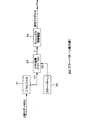
- FIG. 1 shows a configuration example of a reproduction apparatus 1 including a signal quality evaluation apparatus (signal quality evaluation unit 10) according to an embodiment.
- the reproduction signal 1 in this case is configured to perform signal reproduction from an optical disc 90 as an example of a recording medium and obtain an index value Pq for evaluating the reproduction signal quality.
- the reproduction apparatus 1 includes an optical pickup 2 that reproduces bit information from an optical disk 90 that is a removable medium, for example, and a preamplifier unit 3 that converts a signal read by the optical pickup 2 into a reproduction signal (RF signal).
- the reproduction apparatus 1 also includes an AGC (Automatic Gain Control) unit 4 that performs processing on a reproduction signal (RF signal), a waveform equalization unit 5, an A / D conversion unit 6, and a PLL (Phase Locked Loop) unit 7.
- the playback device 1 includes a PR (Partial Response) equalization unit 8 and a maximum likelihood decoding unit 9, and further includes a signal quality evaluation unit 10 and an optical disk controller unit 15 in order to perform PRML decoding processing.
- PR Partial Response
- the reproduced optical disk 90 is, for example, a high-density disk that achieves a 33.4 GB capacity equivalent to BD, or a high-density disk that achieves a 40 GB capacity equivalent to BD.
- the BD equivalent here means that the capacity of one recording layer is 40 GB under the physical conditions of the Blu-ray Disc.
- the recording linear density of bit information recorded on the optical disc for example, it is 55.87 nm / bit in the case of 33.4 GB and 46.65 nm / bit in the case of 40 GB.
- an index for performing appropriate reproduction signal evaluation can be obtained for a reproduction signal from a recording medium having a recording linear density of 46.65 nm / bit or more.
- the optical head unit 2 converges the laser beam on the recording layer of the optical disc 90 through the objective lens, receives the reflected light, and reproduces it as an analog signal indicating the bit information read from the optical disc 90.
- a signal (RF signal) is generated.
- the preamplifier unit 3 amplifies the reproduction signal with a predetermined gain and outputs the amplified signal to the AGC unit 4.
- the AGC unit 4 adjusts the amplitude of the reproduction signal from the preamplifier unit 3 by amplifying or attenuating based on the output from the A / D conversion unit 6, and outputs it to the waveform equalization unit 5.
- the waveform equalization unit 5 has an LPF (Low Pass Filter) characteristic that cuts off the high frequency range of the reproduction signal and an HPF (High Pass Filter) characteristic that blocks the low frequency range of the reproduction signal.
- LPF Low Pass Filter
- HPF High Pass Filter
- the reproduction signal output from the waveform equalization unit 5 is sampled by the A / D conversion unit 6 and converted into digital data.
- the PLL unit 7 Based on the output from the A / D conversion unit 6, the PLL unit 7 generates a reproduction clock synchronized with the reproduction signal after waveform equalization by PLL processing. Sampling in the A / D converter 6 is performed at the timing of the regenerated clock generated by the PLL circuit 7.
- the recovered clock is also used by the PR equalization unit 8 and the maximum likelihood decoding unit 9, the signal quality evaluation unit 10, and the optical disk controller unit 15 for PRML decoding.
- PRML decoding is performed on the reproduced signal converted into digital data by the PR equalization unit 8 and the maximum likelihood decoding unit 9, and binary data DD as a decoding result is obtained.
- the PR equalization unit 8 equalizes the channel response to a target response such as PR (1, 2, 2, 1), PR (1, 2, 2, 2, 1), for example. That is, high frequency noise is suppressed and intentional intersymbol interference is added to the digital reproduction signal.
- a target response such as PR (1, 2, 2, 1), PR (1, 2, 2, 2, 1, 1, for example. That is, high frequency noise is suppressed and intentional intersymbol interference is added to the digital reproduction signal.
- high-density recording of 40 GB or more equivalent to BD is assumed as an optical disk.
- the PR equalization unit 8 has a target response of PR (1, 2, 3, 3, 3, 2, 1), for example.
- the constraint length of the PRML decoding process is 7.
- the reproduction signal RF (EQ) subjected to equalization processing by the PR equalization unit 8 is
- the maximum likelihood decoding unit 9 is configured as, for example, a Viterbi decoder.
- Viterbi detection uses a Viterbi detector consisting of a plurality of states configured in units of continuous bits of a predetermined length and branches represented by transitions between them, and all possible bit sequences are used. A desired bit sequence is efficiently detected from the inside.
- a register that stores a partial response sequence and signal path metric up to that state called a path metric register, and a bit up to that state called a path memory register
- a path metric register a register that stores a sequence flow (path memory)
- a branch metric unit that calculates a partial response sequence and a signal path metric at that bit. It is prepared.
- various bit sequences can be associated in a one-to-one relationship by one of the paths passing through the state.
- the path metric between the partial response sequence that passes through these paths and the actual signal (reproduced signal) is the transition between the states that constitute the above path, that is, the branch metrics described above in the branch sequentially. It is obtained by adding.
- paths with smaller path metrics are sequentially selected while comparing the magnitudes of path metrics of two or less branches that arrive in each state. This can be achieved.
- This selection information to the path memory register information representing the path reaching each state in a bit sequence is stored. The value of the path memory register converges into a bit sequence that finally updates the path metric while being sequentially updated, and the result is output.
- the binarized data DD obtained as a decoding result by the maximum likelihood decoding unit 9 is output to the optical disk controller unit 15 and the signal quality evaluation unit 10.
- the optical disk controller 15 demodulates the reproduction data from the optical disk 90 by performing decoding processing, error correction processing, etc. on the binarized data.
- the signal quality evaluation unit 10 inputs the reproduction signal RF (EQ) subjected to equalization processing by the PR equalization unit 8 and the binarized data DD to evaluate the reproduction signal quality.
- Index value Pq is generated, and the index value Pq is output to the optical disk controller unit 15.
- the optical disk controller unit 15 can evaluate the reproduction signal quality based on the index value Pq.
- the bit detection method by PRML is based on the Euclidean distance between the partial response sequence obtained from the correct bit sequence and the reproduced signal (that is, the path metric for the correct bit sequence) and the partial sequence obtained from the erroneous bit sequence.
- the magnitude relationship of the Euclidean distance between the response sequence and the reproduced signal (that is, the path metric for the erroneous bit sequence) is compared.
- an algorithm that leaves a closer path that is, a path path with a smaller value of the path metric as a more reliable path, and finally detects a path that survived by repeating this operation (maximum likelihood path) is obtained.
- the difference between the path metrics of the top two paths (which are the maximum likelihood path Pa and the second path Pb) having a small path metric value, which are final surviving path selection candidates, is determined. If is large, the surviving path is more accurate, and if it is small, it is more confusing, that is, the possibility of detection error is large. This point will be described with reference to FIG.
- FIG. 2A and 2B are diagrams illustrating the relationship between the maximum likelihood path Pa, the second path Pb, and the actual reproduction signal (the reproduction signal RF (EQ) PR-equalized by the PR equalization unit 8).
- PR (1, 2, 2, 1) is shown.
- FIG. 2A and FIG. 2B each value of “+3, +2, +1, 0, ⁇ 1, ⁇ 2, ⁇ 3” on the vertical axis represents each criterion assumed in PR (1, 2, 2, 1). Shows the level value.
- the maximum likelihood path Pa and the second path Pb shown in the figure can be regarded as two paths that are finally compared with the reproduction signal RF (EQ).
- the path metric value for the maximum likelihood path Pa and the path metric value for the second path Pb are compared, and the path with the smaller value is selected as the surviving path.
- the path metric corresponds to each sampling value of the reproduction signal RF (EQ) obtained at each sampling timing indicated by a black circle in the figure in the maximum likelihood path Pa (or the second path Pb).
- the sum of the Euclidean distances with the respective values obtained at the sampling timing that is, the sum of the branch metrics.
- the Euclidean distance between the maximum likelihood path Pa and the reproduction signal RF (EQ) is expanded and the Euclidean distance between the second path Pb and the reproduction signal RF (EQ) is closer than in the case of FIG. It has become a relationship. That is, in this case, the value of the path metric for the maximum likelihood path Pa is larger than that in the case of FIG. 2A, and conversely, the value of the path metric for the second path Pb is smaller, so that the maximum likelihood as the detection path in this case The certainty of the pass Pa decreases. In other words, in this case, the probability of the other second path Pb is increased, and there is a high possibility that the second path Pb is the most likely path. Therefore, there is a high possibility that the detected path as the maximum likelihood path Pa is a path erroneously detected with respect to the path indicated as the second path Pb.
- the path metric value for the maximum likelihood path Pa is sufficiently smaller than the path metric value for the second path Pb, it can be determined that more probable bit detection is being performed.
- the path metric value for the maximum likelihood path Pa is larger and the path metric value for the second path Pb is smaller, the detection path as the maximum likelihood path Pa is more likely to be erroneous. Judgment can be made.
- the detection accuracy when the PRML method is adopted, the difference between the path metric value for the maximum likelihood path Pa and the path metric value for the second path Pb, that is, the metric difference is obtained. Can be estimated.
- a metric difference (referred to as MD) is defined as follows.
- PB i ”, PA i ”, and “R i ” represent the values of the second path Pb, the maximum likelihood path Pa, and the reproduction signal RF at the same sampling timing, respectively. That is, the metric difference MD in this case is defined as a value obtained by subtracting the value of the path metric for the maximum likelihood path Pa from the value of the path metric for the second path Pb.
- Such a metric difference MD has a maximum value when the value of the path metric for the maximum likelihood path Pa on the right side of the above equation is “0”, that is, when the maximum likelihood path Pa and the reproduction signal RF completely match. It is done. That is, the metric difference MD is information indicating that the larger the value, the higher the detection accuracy (that is, the better the signal quality). From FIG. 2 above, the fact that the maximum likelihood path Pa and the reproduction signal RF completely match in this way means that the path metric for the second path Pb in this case is the maximum likelihood path Pa and the second path Pb. It turns out that it becomes Euclidean distance. Therefore, the maximum value of the metric difference MD as described above is the value of the Euclidean distance between the maximum likelihood path Pa and the second path Pb.
- the minimum value is “0” when the path metric value for the maximum likelihood path Pa and the path metric value for the second path Pb are the same value, that is, the maximum likelihood path Pa in the case of FIG. And the second path Pb are obtained at a position where the reproduction signal RF is exactly in the middle. That is, depending on the value “0” of the metric difference MD, it indicates that both the maximum likelihood path and the second path are equally likely, and therefore indicates the highest possibility of error. become.
- the metric difference MD indicates that the detection accuracy is higher as it is closer to the value (maximum value) of the Euclidean distance between the maximum likelihood path Pa and the second path Pb, and conversely, it is closer to “0” (minimum value). It can be seen that the lower the detection accuracy, the higher the possibility of error.
- an error in the PRML decoding process The incidence can be estimated.
- a metric difference value as a difference between the path metric value for the maximum likelihood path Pa and the path metric value for the second path Pb
- statistical information such as a variance value thereof is obtained.
- the error rate was estimated.
- the difference pattern (error pattern) between the maximum likelihood path and the second path that can actually cause a detection error is limited to some extent.
- the bit sequence pattern of the second pass is caused by a one-bit error such as an edge being shifted by one bit with respect to the bit sequence pattern of the maximum likelihood path, or the disappearance of the 2T mark that is the shortest mark.
- a 2-bit error For example, a 2-bit error.
- the error pattern that actually appeared as an error was limited to almost 100% 1-bit error. Therefore, the signal quality can be properly evaluated by obtaining the distribution of the metric difference for only the 1-bit error which is the only error pattern.
- the PRML class that is actually used several error patterns with a statistically high error frequency are extracted, index values are obtained for each, and the index values are formed by integrating them. ing. This is because the distribution of metric differences (distribution average value and variance) is different for each error pattern, so that it cannot be handled as a single distribution.
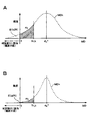
- FIG. 3 shows a distribution example of the metric difference MD for error patterns having different Euclidean distances.
- the vertical axis represents the sample frequency
- the horizontal axis represents the value of the metric difference MD.
- three error patterns PTk (k is 1 to 3) mainly contribute to actual error occurrence, and an example of the distribution of their metric difference MD is shown.
- the distribution shown as MD1 in the figure shows an error pattern PT1 corresponding to a so-called 1-bit error in which the number of bits different between the bit sequence of the maximum likelihood path Pa and the bit sequence of the second pass Pb is one bit. It is assumed that the distribution of the metric difference MD is.
- the distribution shown as MD2 is, for example, the distribution of the metric difference MD for the error pattern PT2 corresponding to the 2-bit error due to the shortest mark shift or the like, and the distribution of the metric difference MD for the error pattern PT3 corresponding to the 3-bit error is MD3. It can be illustrated as In the figure, the distribution indicated as “MD whole” indicates the superposition of these three distributions MD1 to MD3.
- the Euclidean distance between the maximum likelihood path Pa and the second path Pb can be calculated by calculating the square of the difference between the values followed by each path and then calculating the sum thereof. Therefore, at this time, the Euclidean distance “d k 2 ” in each error pattern k is PA i and PB i , respectively, at the same sampling timing in the maximum likelihood path Pa and the second path Pb. Can be expressed as
- the average value of each distribution is a value of the Euclidean distance d k 2 between the maximum likelihood path Pa and the second path Pb in the error pattern k. . That is, if the distribution of the metric difference MD is a Gaussian distribution in this way, the average value of the distribution should be the value of the metric difference MD when the signal quality is the best. Then, the value of the metric difference MD when the signal quality is the best as described above is the maximum likelihood path Pa and the second path Pb according to the calculation formula of the metric difference MD according to [Formula 1]. Is the Euclidean distance value.
- the portion where the value of the metric difference MD shown on the horizontal axis in this figure is “0” indicates that the path metric with respect to the maximum likelihood path Pa and the second path, as can be understood from the description of the previous metric difference MD.
- a portion where the value of the metric difference MD exceeds (below) the portion where the value is “0” indicates a portion that actually becomes a detection error, and this portion becomes an unobservable portion in PRML. That is, when the value of the metric difference MD exceeds “0” and becomes a negative value, the path metric value for the second path Pb is smaller than the path metric value for the maximum likelihood path Pa.
- the path with the smallest path metric value is detected as the maximum likelihood path as understood from the above description, and thus the value of the metric difference MD is determined in this way. It can never be negative. Therefore, the part that causes this detection error cannot be actually observed.
- FIG. 4A shows the distribution (MDk) of the metric difference MD in an error pattern PTk.
- the vertical axis represents the sample frequency and the horizontal axis represents the metric difference MD.
- a predetermined threshold value (Th_k) is set for the value of the metric difference MD, and the error rate is estimated by obtaining the appearance frequency (Fk) of the value of the metric difference MD below this value.
- the appearance frequency Fk of the value of the metric difference MD below the threshold Th_k is correlated with a portion where the metric difference MD ⁇ 0 (bit error rate bER). That is, for example, if the bit error rate bER is increased assuming that the signal quality has deteriorated, the distribution MDk at that time is a distribution in which the base is relatively wide as shown in FIG. 4A, for example. Along with this, the appearance frequency Fk (the area of the Fk portion in the figure) tends to increase. That is, as the bit error rate bER increases, the appearance frequency Fk also increases. On the other hand, when the signal quality is better than that in the case of FIG.
- the distribution MDk has a sharper shape as shown in FIG. 4B, for example.
- the appearance frequency Fk also decreases, and it can be seen that the value of the appearance frequency Fk decreases as the bit error rate bER decreases.
- an index correlating with the bit error rate bER is obtained by the appearance frequency Fk of the value of the metric difference MD below the threshold Th_k.
- a threshold Th_k is appropriately set, and the value of the metric difference MD that falls below the threshold Th_k.
- the signal quality evaluation unit 10 includes an error pattern detection unit 20 (20-1, 20-2... 20-n), a delay compensation unit 21, and a metric difference calculation unit 22 (22-1 22-2... 22 -N), a distribution calculation unit 23 (23-1, 23-2... 23-n), and an index value calculation unit 24.
- Each error pattern detection unit 20 performs binarization obtained by performing PRML decoding processing on the reproduced signal of bit information by partial response equalization in the PR equalization unit 8 and Viterbi decoding in the maximum likelihood decoding unit 9
- Data DD is input, and one or more specific error patterns which are bit patterns longer than the constraint length are detected.
- a detection flag Fdet is output in response to the detection.
- Each error pattern detection unit 20 detects a specific error pattern.
- n error pattern detection units 20-1, 20-2... 20-n are shown as the error pattern detection unit 20, but at least one or more are provided.
- the specific error pattern is an error pattern that has a statistically high error occurrence frequency in the reproduction system.
- PR (1, 2, 3, 3, 3, 2, 1)
- the constraint length in the PRML decoding process performed by the PR equalization unit 8 and the maximum likelihood decoding unit 9 is used. Is 7.
- the following error patterns PTa, PTb, and PTc are detected as specific error patterns that are longer than the constraint length and detected by the error pattern detection unit 20.
- PTa 8-bit pattern that becomes “10111101” when the location where bit inversion occurs is indicated by “1”
- PTb 13 bits that becomes “1011110111101” when the location where bit inversion occurs is indicated by “1”
- Pattern PTc 14-bit pattern that becomes “10111100111101” when the place where bit inversion occurs is indicated by “1” Note that the place where bit inversion occurs in the above is “1” “ “0” is a different place. In the correct pattern and the error pattern, some of the “1” locations are not different, but all “1” locations are different bit patterns.
- an error pattern dominant as an error occurrence frequency is selected and its distribution is used. Therefore, if there is one specific error pattern used as the dominant error pattern, only one error pattern detection unit 20 (for example, only the error pattern detection unit 20-1) may be used. If there are two dominant error patterns and two specific error patterns used for index value calculation, two error pattern detection units 20 (for example, error pattern detection units 20-1 and 20-2) are provided. What is necessary is just to provide. In that sense, “n” is the number of selected specific error patterns. Since the metric difference calculation unit 22 and the distribution calculation unit 23 are also provided corresponding to the error pattern detection unit 20, the meaning of “n” is the same.
- the above three error patterns PTa, PTb, and PTc are specific error patterns.
- error pattern detection units 20-1, 20-2, and 20-3 are provided. . Then, the error pattern detection unit 20-1 detects the error pattern PTa, the error pattern detection unit 20-2 detects the error pattern PTb, and the error pattern detection unit 20-3 performs an operation of detecting the error pattern PTc.
- One error pattern detection unit 20 includes a shift register 31, an error pattern generation unit 32, an exclusive OR operation unit 33, and a run length restriction confirmation unit 34.
- the error pattern detection unit 20 first receives an input bit string as the binarized data DD by the shift register 31 and captures data in the same clock section as the specific error pattern. For example, when an 8-bit specific error pattern PTa is to be detected, data in an 8-clock interval is captured. Then, the data in the clock interval is output to the exclusive OR calculator 33 (output X1). Further, the error pattern generation unit 32 outputs a specific error pattern. For example, an 8-bit pattern “10111101” is output to the exclusive OR calculator 33 as the specific error pattern PTa (output X2).
- the exclusive OR operation unit 33 performs an EX-OR operation of the bit pattern (X1) from the shift register 31 and the specific error pattern (X2). That is, with respect to the bit pattern from the shift register 31, bit inversion is performed at a location where “1” is set in “10111101” of the specific error pattern PTa.
- the calculation result Y is supplied to the run length limit confirmation unit 34.
- the run length restriction confirmation unit 34 checks whether or not the run length restriction of the modulation code is satisfied. That is, the 8-bit bit pattern supplied from the shift register 31 to the exclusive OR operation unit 33 and the 8-bit bit pattern in which the bit inversion of the portion where “1” is set in the specific error pattern PTa are specified. There is a relationship between the maximum likelihood path where the error corresponding to the error pattern PTa may occur and the second path. However, this is the case when the 8-bit pattern of the exclusive OR operation result satisfies the run length restriction. This is because if the run length restriction is not satisfied, it cannot be a bit sequence of false detection in the first place. Accordingly, when the exclusive OR operation result satisfies the run length restriction, an error pattern is detected. In this case, the run length restriction confirmation unit 34 outputs the detection flag Fdet.
- the operation of the error pattern detection unit 20-1 for detecting the specific error pattern PTa has been described as an example, but the error pattern detection unit 20-2 for detecting the specific error pattern PTb or the specific error pattern PTc is detected.
- the concept of the configuration and operation of the error pattern detection unit 20-3 is the same.
- the shift register 31 supplies the binarized data DD for 13 clock intervals to the exclusive OR operation unit 33.
- the error pattern generation unit 32 supplies a 13-bit pattern that becomes “1011110111101” as the specific error pattern PTb to the exclusive OR operation unit 33. If these exclusive OR calculation results satisfy the run length restriction, the detection flag Fdet is output.
- the reproduction signal RF (EQ) that is the output of the PR equalization unit 8 in FIG. 1 is input to the delay compensation unit 21.
- the delay compensation unit 21 performs delay compensation on the reproduced signal waveform after PR equalization in consideration of the Viterbi detection process in the maximum likelihood decoding unit 9 and the detection process in the error pattern detection unit 20, and the error pattern detection unit The synchronization relationship between the detection flag Fdet output from 20 and the reproduction signal RF (EQ) is ensured.
- the metric difference calculation units 22 (22-1, 22-2... 22-n) are provided corresponding to the error pattern detection units 20 (20-1, 20-2... 20-n), respectively. .
- Each metric difference calculation unit 22 is supplied with a detection flag Fdet from the corresponding error pattern detection unit 20 and a reproduction signal RF (EQ) via the delay compensation unit 21.
- the metric difference calculation unit 22 obtains a metric difference for the reproduction signal RF (EQ) when the specific error pattern is detected.
- Equation 2 calculation of the metric difference requires information on the maximum likelihood path and the second path together with the reproduction signal RF (EQ). Then, the maximum likelihood path and the second path can be obtained from the information of the reproduction signal RF (EQ) and the detection flag Fdet.
- the metric difference calculation unit 22-1 is supplied with the detection flag Fdet for the specific error pattern PTa in the 8-clock section “10111101” in the error pattern detection unit 20-1.
- the bit string in a relationship in which all the bits of “1” are inverted in the reproduction signal RF (EQ) of the section becomes the maximum likelihood path and the second path.
- the distribution calculation units 23 respectively calculate the metric differences obtained by the metric difference calculation units 22 (22-1, 22-2,... 22-n). Perform distribution calculation. For example, the distribution as described in FIGS. 3 and 4 is obtained. In this way, a difference metric distribution representing the detection margin for each specific error pattern can be obtained.
- the index value calculation unit 24 calculates a comprehensive index value Pq using the distribution for each specific error pattern obtained by each distribution calculation unit 23 (23-1, 23-2... 23-n). 1 is output to the optical disk controller 15 in FIG. That is, the distribution calculation unit 23 and the index value calculation unit 24 perform processing for generating an index value Pq for generating a reproduction signal quality index value using the metric difference distribution obtained by the metric difference calculation unit 22.
- the specific process may be the process described with reference to FIGS. 2 and 3, for example, the process described in Patent Document 4, and various examples are conceivable.
- the signal quality evaluation unit 10 of the present embodiment is configured as described above.
- the above-described specific error patterns PTa, PTb, and PTc are employed as the specific error pattern to be detected. The reason for this will be described.
- the optical disk 90 is a high-density disk that achieves a recording linear density of 46.65 nm / bit or more, that is, a 40 GB capacity equivalent to BD.
- the frequency characteristics of the channel, particularly high-frequency components are significantly degraded, and the code interference interference of the reproduced signal becomes very strong.
- a new PRML class that conforms to the frequency characteristics is introduced, sufficient reproduction performance cannot be ensured.
- the dominant error pattern also changes from the previous condition with the frequency characteristics of the reproduction channel and the PRML class change. Specifically, due to the high frequency cutoff of the optical amplitude transfer function (MTF), the short mark reproduction signal amplitude is extremely reduced, and the reproduction signal amplitude of not only the shortest mark but also the second shortest mark can be obtained. Absent.
- MTF optical amplitude transfer function
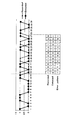
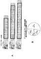
- the error pattern in PRML maximum likelihood decoding has been understood in bit units or about 1 bit shift of the shortest mark (that is, these errors are used to express signal quality). On the other hand, it was enough to consider only the pattern). On the other hand, under ultra-high density recording conditions, as shown in Fig. 7, many new block errors including polarity reversal of recording marks and spaces occurred. To come. This makes the contribution of these block-like error patterns dominant at the overall error rate. Since the block-like error pattern has an error propagation property, an error may occur over a very long interval of 10 clock intervals or more in some cases.
- FIG. 7 Illustrated in FIG. 7 is an optical simulation waveform at a linear density (46.65 nm / bit) equivalent to BD40GB detected by PRML class PR (1, 2, 3, 3, 3, 2, 1) ML.
- PRML class PR (1, 2, 3, 3, 3, 2, 1) ML.
- This is an example of an error occurring when In contrast to the recording data pattern (correct answer pattern) indicated by the broken line, actually, the binarized data DD which is erroneous in the 14 clock interval has been detected as indicated by the solid line.
- the bit pattern of the portion where the error has occurred is shown in the lower part of the figure. In this case, the recorded bit information (that is, the correct pattern) is “10001100001100”, whereas the detected bit information (the error is The generated pattern) is “00110000110001”.
- the only considered error pattern is an isolated error, and the length thereof is less than the constraint length of PRML maximum likelihood decoding, so-called Viterbi detection.
- the index value using the previous error pattern has a poor correlation with the reproduction signal quality. That is, the index value is less likely to be a value that appropriately represents the reproduction signal quality. Therefore, in the present embodiment, a block-like error pattern that becomes dominant in high-density recording equivalent to BD of 40 GB or more is taken into consideration, and an error pattern longer than the Viterbi constraint length is newly detected and incorporated in signal evaluation.
- the specific error patterns PTa, PTb, and PTc described above are error patterns that are employed for signal quality evaluation as patterns longer than the PRML constraint length for the above reasons.
- FIG. 8A shows specific error patterns PTa, PTb, PTc and specific pattern examples thereof.
- the thick frame in the row indicated as “bit error” corresponds to the specific error patterns PTa, PTb, and PTc. That is, the pattern where the bit inversion occurs between the correct pattern and the error pattern is “1”.
- the specific error pattern PTa is “10111101”, and examples of the correct answer pattern and the error pattern corresponding to this are “100001100” and “00110001”.
- the specific error pattern PTb is “1011110111101”, and examples of the correct answer pattern and the error pattern corresponding to this are “10000110001100” and “0011000110001”.
- the specific error pattern PTc is “10111100111101”, and examples of the correct pattern and error pattern corresponding to this are “10001100001100” and “001100000110001”, that is, the patterns illustrated in FIG.
- three error pattern detection units 20-1 to 20-3 are provided as the error pattern detection units 20-1 to 20-n in FIG.
- the three error pattern detection units 20-1 to 20-3 detect bit patterns corresponding to the specific error patterns PTa, PTb, and PTc.
- the index value is calculated from the distribution of the metric difference when the specific error pattern is detected.
- the index value Pq is not appropriate unless the specific error patterns PTa, PTb, and PTc are actually dominant error patterns.
- the occurrence frequency of each bit error pattern when the recording linear density is 44 GB in terms of BD is examined, and the result is as shown in FIG. 8B. That is, the specific error pattern PTa was 53.7%, the specific error pattern PTb was 17.1%, the specific error pattern PTc was 7.6%, and the other patterns were 21.5%. That is, the three specific error patterns PTa, PTb, and PTc have a dominant situation in which almost 80% of the total number of errors is covered. In this case, by calculating the index value Pq based on the detection of the specific error patterns PTa, PTb, PTc, it can be said that the value has high correlation with the bit error rate and is highly accurate.
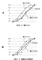
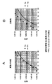
- FIGS. 9 and 10 show simulation results. Each of FIGS. 9 and 10 shows the correlation between the signal quality evaluation value and the bit error rate in the optical simulation model.
- the horizontal axis is the index value
- the vertical axis is the bit error rate (bER)
- the calculated index value is plotted with black triangles and black squares.
- the solid line indicated by TH in the figure is the theoretical value of the relationship between the index value and the bit error rate when Gaussian noise is assumed.
- FIG. 9A and FIG. 10A correspond to an embodiment in which all new specific error patterns PTa, PTb, PTc are added to a specific error pattern shorter than a conventional constraint length. This is a case where an evaluation value is obtained by performing the same calculation as in the case indicated by.
- FIG. 10B show a case where an evaluation value is obtained using only the previous specific error pattern as a comparative example.
- FIG. 11 shows an example of the previous specific error pattern.
- the error pattern PTd1 is a pattern corresponding to a bit error as an edge shift
- the error pattern PTd2 is a pattern corresponding to a bit error of continuous 2T shift.
- FIG. 9 shows a case where detection is performed with PR (1, 2, 2, 2, 1) ML, which is 5 tap PRML, under a linear density condition of BD conversion of 33 GB.
- the comparative example and the example of the embodiment are in good agreement with the theoretical value, and in either method, high accuracy can be expected as the index value Pq.
- FIG. 10 shows the case of an ultra-high linear density condition of 40 GB in BD conversion far exceeding the conventional optical disk, and detection is performed with PR (1,2,3,3,3,2,1) ML which is 7 tap PRML. Is going. Under this condition, the result of the comparative example of FIG.
- the index value Pq is greatly deviated from the theoretical value, and it is expected that the index value and the error rate correlation vary depending on various signal deterioration factors in the actual machine conditions. The accuracy has greatly deteriorated.
- the index value Pq matches the theoretical value equivalent to the conventional optical disk condition, and high accuracy (against the error) Rate correlation).
- PRML decoding performed by PR (1, 2, 3, 3, 3, 2, 1) ML and performed by PR equalization unit 8 and maximum likelihood decoding unit 9 is performed.
- the constraint length in the process is 7.
- the error pattern detection unit 20 detects the specific error patterns PT1 “10111101”, PT2 “1011110111101”, and PT3 “10111100111101” (“1” in each pattern indicates a place where bit inversion occurs. ) Then, a metric difference is calculated for these specific error patterns, and a reproduction signal quality index value Pq is generated using the distribution of the metric difference. Thereby, a highly accurate index value as a signal quality evaluation value can be obtained.
- the “arithmetic processing system” referred to below indicates a processing system corresponding to one specific error pattern, that is, a processing system of the error pattern detection unit 20, the metric difference calculation unit, and the distribution calculation unit 23.
- a processing system of the error pattern detection unit 20 the metric difference calculation unit, and the distribution calculation unit 23.
- FIG. 5 of the above-described embodiment it is shown as having n arithmetic processing systems, but the following is a specific example.
- Example 8 Two or more arithmetic processing systems are provided (n ⁇ 2), one of the first specific error patterns (for example, any one of PTa, PTb, and PTc) and one or a plurality of second specific error patterns
- Example 9 of calculating index value Pq by using the example 9 Three or more arithmetic processing systems are provided (n ⁇ 3), two specific error patterns as the first specific error pattern, and one or a plurality of second specific Configuration example for calculating index value Pq using error pattern
- Example 10 Four or more arithmetic processing systems are provided (n ⁇ 4), three specific error patterns as first specific error patterns, and one or more second Of calculating the index value Pq using the specific error pattern
- the bit error rate is used particularly in high-density recording equivalent to or higher than BD40GB by using the first specific error pattern (for example, one or more of PTa, PTb, and PTc).
- the index value Pq having a high correlation can be calculated.
- the configuration of the playback device is not limited to this.
- the PR class is effective (that is, the error can be sufficiently low and practical) at a recording line density equivalent to BD equivalent to 40 GB or more
- the above-described specific error patterns PTa, PTb, and PTc are dominant. Even when the PR class is adopted, the technique of the present disclosure is effective.
- the specific error pattern longer than the constraint length patterns other than the specific error patterns PT1, PT2, and PT3 are also conceivable.
- a specific error pattern in a long section (section exceeding the constraint length) corresponding to a block-like error may be selected in accordance with a PR class selected according to high-density recording, frequency characteristics, or the like.
- the technology of the present disclosure can be widely applied to decoding bit information reproduced from a recording medium and decoding bit information transmitted.
- the recording medium is not limited to an optical disc, and any recording medium is assumed.
- this technique can also take the following structures.
- An error pattern detection unit for detecting a specific error pattern of For the specific error pattern detected by the error pattern detector, a metric difference calculator that calculates a metric difference;
- An index value generation unit that generates an index value of the reproduction signal quality using the distribution of the metric difference obtained by the metric difference calculation unit;
- a signal quality evaluation apparatus A signal quality evaluation apparatus.
- At least one of the specific error patterns is The signal quality evaluation apparatus according to (1) above, which is an 8-bit pattern that becomes “10111101” when a location where bit inversion occurs is indicated by “1”.
- At least one of the specific error patterns is The signal quality evaluation apparatus according to the above (1) or (2), which is a 13-bit pattern that becomes “1011110111101” when a place where bit inversion occurs is indicated by “1”.
- At least one of the specific error patterns is The signal quality evaluation apparatus according to any one of (1) to (3) above, which is a 14-bit pattern that becomes “10111100111101” when a location where bit inversion occurs is indicated by “1”.
- the error pattern detection unit detects one or a plurality of second specific error patterns that are bit patterns shorter than the constraint length
- the metric difference calculation unit calculates a metric difference for each of the first and second specific error patterns detected by the error pattern detection unit.
- 1 playback device 8 PR equalization unit, 9 maximum likelihood decoding unit, 10 signal quality evaluation unit, 20 (20-1 ... 20-n) error pattern detection unit, 21 delay compensation unit, 22 (22-1 ⁇ ⁇ 22-n) Metric difference calculation unit, 23 (23-1 ... 23-n) Distribution calculation unit, 24 index value calculation unit
Landscapes
- Engineering & Computer Science (AREA)
- Signal Processing (AREA)
- Physics & Mathematics (AREA)
- Probability & Statistics with Applications (AREA)
- Theoretical Computer Science (AREA)
- Signal Processing For Digital Recording And Reproducing (AREA)
- Error Detection And Correction (AREA)
Abstract
Priority Applications (5)
| Application Number | Priority Date | Filing Date | Title |
|---|---|---|---|
| JP2014519884A JP6090315B2 (ja) | 2012-06-04 | 2013-04-26 | 信号品質評価装置、信号品質評価方法、再生装置 |
| EP13799823.3A EP2858070B1 (fr) | 2012-06-04 | 2013-04-26 | Dispositif d'évaluation de qualité de signal, procédé d'évaluation de qualité de signal et dispositif de reproduction |
| CN201380028675.0A CN104335278B (zh) | 2012-06-04 | 2013-04-26 | 信号质量评估装置、信号质量评估方法以及再生装置 |
| KR1020147032852A KR102071092B1 (ko) | 2012-06-04 | 2013-04-26 | 신호 품질 평가 장치, 신호 품질 평가 방법, 재생 장치 |
| US14/403,482 US9461672B2 (en) | 2012-06-04 | 2013-04-26 | Signal quality evaluation apparatus, signal quality evaluation method, and reproducing device |
Applications Claiming Priority (2)
| Application Number | Priority Date | Filing Date | Title |
|---|---|---|---|
| JP2012126966 | 2012-06-04 | ||
| JP2012-126966 | 2012-06-04 |
Publications (1)
| Publication Number | Publication Date |
|---|---|
| WO2013183385A1 true WO2013183385A1 (fr) | 2013-12-12 |
Family
ID=49711786
Family Applications (1)
| Application Number | Title | Priority Date | Filing Date |
|---|---|---|---|
| PCT/JP2013/062487 Ceased WO2013183385A1 (fr) | 2012-06-04 | 2013-04-26 | Dispositif d'évaluation de qualité de signal, procédé d'évaluation de qualité de signal et dispositif de reproduction |
Country Status (7)
| Country | Link |
|---|---|
| US (1) | US9461672B2 (fr) |
| EP (1) | EP2858070B1 (fr) |
| JP (1) | JP6090315B2 (fr) |
| KR (1) | KR102071092B1 (fr) |
| CN (1) | CN104335278B (fr) |
| TW (1) | TWI530942B (fr) |
| WO (1) | WO2013183385A1 (fr) |
Cited By (2)
| Publication number | Priority date | Publication date | Assignee | Title |
|---|---|---|---|---|
| WO2018042814A1 (fr) * | 2016-08-30 | 2018-03-08 | ソニーセミコンダクタソリューションズ株式会社 | Dispositif d'évaluation de qualité de signal, procédé de génération de valeur d'évaluation de qualité de signal, et dispositif de reproduction |
| WO2019102733A1 (fr) | 2017-11-27 | 2019-05-31 | ソニーセミコンダクタソリューションズ株式会社 | Dispositif de décodage et procédé de décodage |
Citations (5)
| Publication number | Priority date | Publication date | Assignee | Title |
|---|---|---|---|---|
| JP3711140B2 (ja) | 2005-03-07 | 2005-10-26 | 株式会社東芝 | 情報記録再生装置及びその信号評価方法 |
| JP3857685B2 (ja) | 2003-01-28 | 2006-12-13 | 日本電気株式会社 | 信号評価方法と情報記録再生装置と情報再生装置及び情報媒体 |
| WO2010001588A1 (fr) | 2008-07-01 | 2010-01-07 | パナソニック株式会社 | Procédé pour évaluer un signal reproduit, dispositif d'évaluation de signal reproduit et dispositif de disque optique équipé de celui-ci |
| WO2010090136A1 (fr) * | 2009-02-03 | 2010-08-12 | 日立コンシューマエレクトロニクス株式会社 | Procédé d'évaluation de signal de lecture et lecteur de disque optique |
| JP4750488B2 (ja) | 2005-07-08 | 2011-08-17 | ソニー株式会社 | 評価装置、再生装置、評価方法 |
Family Cites Families (10)
| Publication number | Priority date | Publication date | Assignee | Title |
|---|---|---|---|---|
| US6801061B2 (en) | 2002-08-29 | 2004-10-05 | Micron Technology, Inc. | Reduced current input buffer circuit |
| JP2005285153A (ja) * | 2004-03-26 | 2005-10-13 | Toshiba Corp | 情報記録媒体、情報再生装置、情報再生方法、および情報記録方法 |
| CN100570728C (zh) * | 2004-05-07 | 2009-12-16 | 株式会社日立制作所 | 再生信号的评价方法以及光盘装置 |
| JP4313755B2 (ja) * | 2004-05-07 | 2009-08-12 | 株式会社日立製作所 | 再生信号の評価方法および光ディスク装置 |
| JP4622632B2 (ja) * | 2005-03-31 | 2011-02-02 | ソニー株式会社 | 最尤復号装置、信号評価方法、再生装置 |
| JP4900391B2 (ja) * | 2006-09-11 | 2012-03-21 | 日本電気株式会社 | 光学的情報記録再生装置及び記録マーク品質測定方法 |
| JP5003284B2 (ja) * | 2007-05-24 | 2012-08-15 | 日本電気株式会社 | 信号品質測定装置及び情報再生装置 |
| US20080299403A1 (en) * | 2007-06-01 | 2008-12-04 | Weyerhaeuser Co. | Gas barrier packaging board |
| JPWO2009041598A1 (ja) * | 2007-09-26 | 2011-01-27 | 日本電気株式会社 | 信号品質評価装置、方法、及び、情報記録再生装置 |
| JP2012048774A (ja) * | 2010-08-25 | 2012-03-08 | Sony Corp | 対物レンズ、レンズ製造方法、光学ドライブ装置 |
-
2013
- 2013-04-25 TW TW102114898A patent/TWI530942B/zh active
- 2013-04-26 EP EP13799823.3A patent/EP2858070B1/fr active Active
- 2013-04-26 KR KR1020147032852A patent/KR102071092B1/ko not_active Expired - Fee Related
- 2013-04-26 US US14/403,482 patent/US9461672B2/en not_active Expired - Fee Related
- 2013-04-26 CN CN201380028675.0A patent/CN104335278B/zh active Active
- 2013-04-26 WO PCT/JP2013/062487 patent/WO2013183385A1/fr not_active Ceased
- 2013-04-26 JP JP2014519884A patent/JP6090315B2/ja active Active
Patent Citations (5)
| Publication number | Priority date | Publication date | Assignee | Title |
|---|---|---|---|---|
| JP3857685B2 (ja) | 2003-01-28 | 2006-12-13 | 日本電気株式会社 | 信号評価方法と情報記録再生装置と情報再生装置及び情報媒体 |
| JP3711140B2 (ja) | 2005-03-07 | 2005-10-26 | 株式会社東芝 | 情報記録再生装置及びその信号評価方法 |
| JP4750488B2 (ja) | 2005-07-08 | 2011-08-17 | ソニー株式会社 | 評価装置、再生装置、評価方法 |
| WO2010001588A1 (fr) | 2008-07-01 | 2010-01-07 | パナソニック株式会社 | Procédé pour évaluer un signal reproduit, dispositif d'évaluation de signal reproduit et dispositif de disque optique équipé de celui-ci |
| WO2010090136A1 (fr) * | 2009-02-03 | 2010-08-12 | 日立コンシューマエレクトロニクス株式会社 | Procédé d'évaluation de signal de lecture et lecteur de disque optique |
Cited By (4)
| Publication number | Priority date | Publication date | Assignee | Title |
|---|---|---|---|---|
| WO2018042814A1 (fr) * | 2016-08-30 | 2018-03-08 | ソニーセミコンダクタソリューションズ株式会社 | Dispositif d'évaluation de qualité de signal, procédé de génération de valeur d'évaluation de qualité de signal, et dispositif de reproduction |
| TWI638539B (zh) * | 2016-08-30 | 2018-10-11 | 日商索尼半導體解決方案公司 | Signal quality evaluation device, signal quality evaluation value generation method, and regeneration device |
| WO2019102733A1 (fr) | 2017-11-27 | 2019-05-31 | ソニーセミコンダクタソリューションズ株式会社 | Dispositif de décodage et procédé de décodage |
| US11070238B2 (en) | 2017-11-27 | 2021-07-20 | Sony Semiconductor Solutions Corporation | Decoding device and decoding method |
Also Published As
| Publication number | Publication date |
|---|---|
| TW201351402A (zh) | 2013-12-16 |
| EP2858070B1 (fr) | 2019-08-14 |
| KR20150023281A (ko) | 2015-03-05 |
| EP2858070A4 (fr) | 2016-06-15 |
| TWI530942B (zh) | 2016-04-21 |
| CN104335278A (zh) | 2015-02-04 |
| US20150143208A1 (en) | 2015-05-21 |
| KR102071092B1 (ko) | 2020-01-29 |
| JP6090315B2 (ja) | 2017-03-08 |
| JPWO2013183385A1 (ja) | 2016-01-28 |
| US9461672B2 (en) | 2016-10-04 |
| CN104335278B (zh) | 2018-04-03 |
| EP2858070A1 (fr) | 2015-04-08 |
Similar Documents
| Publication | Publication Date | Title |
|---|---|---|
| RU2497205C2 (ru) | Способ оценки сигнала воспроизведения, устройство оценки сигнала воспроизведения и устройство на оптическом диске, оснащенное таким устройством оценки сигнала воспроизведения | |
| JP3926688B2 (ja) | 再生信号品質評価方法および情報再生装置 | |
| JP4622632B2 (ja) | 最尤復号装置、信号評価方法、再生装置 | |
| JP4750488B2 (ja) | 評価装置、再生装置、評価方法 | |
| JP3857685B2 (ja) | 信号評価方法と情報記録再生装置と情報再生装置及び情報媒体 | |
| JP5441906B2 (ja) | 再生信号評価方法、再生信号評価装置及びこれを備えた光ディスク装置 | |
| JP6090315B2 (ja) | 信号品質評価装置、信号品質評価方法、再生装置 | |
| CN109643559B (zh) | 信号质量评估设备、信号质量评估值生成方法及再现设备 | |
| US7441177B2 (en) | Information reproduction apparatus and method using maximum likelihood decoding | |
| US20100085851A1 (en) | Method and apparatus for evaluating information recording medium | |
| JP2010140551A (ja) | 光ディスク再生方法および再生装置 | |
| JP2005332437A (ja) | 再生信号評価方法及び情報記録再生装置 | |
| JP2005093043A (ja) | 非対称データチャネルでのビット再生方法 | |
| JPWO2009122642A1 (ja) | 再生信号品質評価装置及び方法 | |
| JP2008300023A (ja) | 情報再生装置及び方法 | |
| JP2009238283A (ja) | 光学的情報再生装置、情報再生方法 |
Legal Events
| Date | Code | Title | Description |
|---|---|---|---|
| 121 | Ep: the epo has been informed by wipo that ep was designated in this application |
Ref document number: 13799823 Country of ref document: EP Kind code of ref document: A1 |
|
| WWE | Wipo information: entry into national phase |
Ref document number: 2013799823 Country of ref document: EP |
|
| ENP | Entry into the national phase |
Ref document number: 20147032852 Country of ref document: KR Kind code of ref document: A |
|
| WWE | Wipo information: entry into national phase |
Ref document number: 14403482 Country of ref document: US |
|
| ENP | Entry into the national phase |
Ref document number: 2014519884 Country of ref document: JP Kind code of ref document: A |
|
| NENP | Non-entry into the national phase |
Ref country code: DE |