EP2858081A1 - Positionsschalter - Google Patents
Positionsschalter Download PDFInfo
- Publication number
- EP2858081A1 EP2858081A1 EP20140184556 EP14184556A EP2858081A1 EP 2858081 A1 EP2858081 A1 EP 2858081A1 EP 20140184556 EP20140184556 EP 20140184556 EP 14184556 A EP14184556 A EP 14184556A EP 2858081 A1 EP2858081 A1 EP 2858081A1
- Authority
- EP
- European Patent Office
- Prior art keywords
- shaft
- rotation
- cam
- pusher
- position switch
- Prior art date
- Legal status (The legal status is an assumption and is not a legal conclusion. Google has not performed a legal analysis and makes no representation as to the accuracy of the status listed.)
- Granted
Links
Images



Classifications
-
- H—ELECTRICITY
- H01—ELECTRIC ELEMENTS
- H01H—ELECTRIC SWITCHES; RELAYS; SELECTORS; EMERGENCY PROTECTIVE DEVICES
- H01H3/00—Mechanisms for operating contacts
- H01H3/32—Driving mechanisms, i.e. for transmitting driving force to the contacts
- H01H3/46—Driving mechanisms, i.e. for transmitting driving force to the contacts using rod or lever linkage, e.g. toggle
-
- H—ELECTRICITY
- H01—ELECTRIC ELEMENTS
- H01H—ELECTRIC SWITCHES; RELAYS; SELECTORS; EMERGENCY PROTECTIVE DEVICES
- H01H3/00—Mechanisms for operating contacts
- H01H3/22—Power arrangements internal to the switch for operating the driving mechanism
- H01H3/30—Power arrangements internal to the switch for operating the driving mechanism using spring motor
- H01H3/3005—Charging means
- H01H3/3015—Charging means using cam devices
-
- H—ELECTRICITY
- H01—ELECTRIC ELEMENTS
- H01H—ELECTRIC SWITCHES; RELAYS; SELECTORS; EMERGENCY PROTECTIVE DEVICES
- H01H21/00—Switches operated by an operating part in the form of a pivotable member acted upon directly by a solid body, e.g. by a hand
- H01H21/02—Details
- H01H21/18—Movable parts; Contacts mounted thereon
- H01H21/22—Operating parts, e.g. handle
- H01H21/24—Operating parts, e.g. handle biased to return to normal position upon removal of operating force
- H01H21/28—Operating parts, e.g. handle biased to return to normal position upon removal of operating force adapted for actuation at a limit or other predetermined position in the path of a body, the relative movement of switch and body being primarily for a purpose other than the actuation of the switch, e.g. door switch, limit switch, floor-levelling switch of a lift
-
- H—ELECTRICITY
- H01—ELECTRIC ELEMENTS
- H01H—ELECTRIC SWITCHES; RELAYS; SELECTORS; EMERGENCY PROTECTIVE DEVICES
- H01H3/00—Mechanisms for operating contacts
- H01H3/02—Operating parts, i.e. for operating driving mechanism by a mechanical force external to the switch
- H01H3/04—Levers
-
- H—ELECTRICITY
- H01—ELECTRIC ELEMENTS
- H01H—ELECTRIC SWITCHES; RELAYS; SELECTORS; EMERGENCY PROTECTIVE DEVICES
- H01H3/00—Mechanisms for operating contacts
- H01H3/02—Operating parts, i.e. for operating driving mechanism by a mechanical force external to the switch
- H01H3/16—Operating parts, i.e. for operating driving mechanism by a mechanical force external to the switch adapted for actuation at a limit or other predetermined position in the path of a body, the relative movement of switch and body being primarily for a purpose other than the actuation of the switch, e.g. for a door switch, a limit switch, a floor-levelling switch of a lift
-
- H—ELECTRICITY
- H01—ELECTRIC ELEMENTS
- H01H—ELECTRIC SWITCHES; RELAYS; SELECTORS; EMERGENCY PROTECTIVE DEVICES
- H01H3/00—Mechanisms for operating contacts
- H01H3/32—Driving mechanisms, i.e. for transmitting driving force to the contacts
- H01H3/38—Driving mechanisms, i.e. for transmitting driving force to the contacts using spring or other flexible shaft coupling
-
- H—ELECTRICITY
- H01—ELECTRIC ELEMENTS
- H01H—ELECTRIC SWITCHES; RELAYS; SELECTORS; EMERGENCY PROTECTIVE DEVICES
- H01H3/00—Mechanisms for operating contacts
- H01H3/32—Driving mechanisms, i.e. for transmitting driving force to the contacts
- H01H3/42—Driving mechanisms, i.e. for transmitting driving force to the contacts using cam or eccentric
-
- H—ELECTRICITY
- H01—ELECTRIC ELEMENTS
- H01H—ELECTRIC SWITCHES; RELAYS; SELECTORS; EMERGENCY PROTECTIVE DEVICES
- H01H2235/00—Springs
- H01H2235/01—Spiral spring
Definitions
- a mechanical position switch comprises a body, generally of parallelepiped shape, and a head fixed on the body along a main axis.
- the switch comprises a switching device and actuating means arranged to cooperate with the switching device.
- the actuating means comprise an actuating member such as for example a lever operable in pivoting. The detection of a movement of an object is performed by mechanical actuation of the actuating member.
- the actuating means also comprise a shaft rotated by the actuating member about an axis of rotation and a plunger mounted on a spring and for controlling the switching device.
- a cam mechanism arranged on the shaft and the pusher, makes it possible to convert the rotational movement of the shaft into a translation movement of the pusher and vice versa.
- Licences FR2134814 and US4133991 describe a position switch as known in the state of the art.
- the actuating member is actuated with an amplitude of plus or minus 70 ° with respect to an axial direction. To avoid any risk of breakage of the switch, it is necessary to take into account this maximum angle when installing the switch relative to the object whose movement is to be detected. Of course, it is possible to provide position switches having greater rotational amplitudes but this can also be problematic.
- each cam serves to activate the pusher on either side of the main axis.
- Each cam is arranged to act on a distinct side, depending on the direction of rotation of the shaft.
- the object of the invention is to provide a position switch allowing rotation of its actuating member at an angle of about 90 ° without risk of locking in this position, the solution of the invention not requiring the use a torsion spring or misalignment of the fulcrum between the shaft and the pusher.
- the first torque is zero on the second range of rotation of the shaft.
- first cam and the second cam are juxtaposed along the shaft and the first cam follower and the second cam follower are juxtaposed on the pusher.
- the spring is a compression spring urging the pusher in translation in an axial direction.
- the actuating member is a lever or a flexible rod.
- the head is removably attached to the body and is rotatable about the main axis relative to the body.
- the tree is housed inside the head.
- the switching device is housed inside the body.
- the pusher is arranged between the shaft and the switching device.
- the pivoting plane of the actuating member is parallel to the main axis and perpendicular to the axis of rotation of the shaft.
- the actuating member is movable in rotation more or less 90 ° with respect to a rest position located along the main axis.
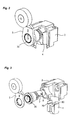
- a mechanical position switch typically comprises a body 1, generally of parallelepipedal shape, and a head 2 fixed on the body.
- the assembly of the head on the body is made along an axis called the main axis (X).
- the head 2 is preferably removable relative to the body 1 so as to take different orientations around the main axis.
- the position switch comprises an actuating member 3 fixed on the head 2, composed for example of a lever or a flexible rod, and positioned in the path of the object 6 whose movement is to be detected.
- This actuating member 3 is pivotally movable. It is fixed on a shaft 30 movable in rotation about an axis of rotation (Y).
- this axis of rotation is perpendicular to the main axis (X) and located in the same plane as this one.
- the shaft 30 is rotated about its axis by the actuating member 3 when the latter is pivotally biased. Initially, the actuating member 3 is in a rest position, for example along the main axis (X).
- the position switch also comprises a pusher 4 arranged to cooperate with the shaft 30.
- This pusher 4 is movable in translation in a direction parallel to the main axis (X) and held against the shaft 30 by a spring 40, preferentially a compression spring.
- the position switch comprises a cam mechanism arranged on the pusher 4 and on the shaft 30 to transform the rotational movement of the shaft 30 into a translational movement of the pusher 4 during an action on the body. actuating 3, or transforming the translational movement of the pusher 4 biased by its spring 40 into a rotational movement of the shaft 30 during the reaction movement.
- the position switch comprises a switching device 5 controlled by the pusher 4 in translation. An electrical signal is transmitted by the switch when the switching device 5 is in the closed state. According to the configuration of the position switch (normally open or normally closed), the electrical signal will be transmitted when the actuating member 3 is in the rest position or in the actuated position.
- the Figures 1A to 1C illustrate the operating principle of a mechanical position switch.
- the actuating member 3 is pivotally actuated by the moving object 6. Pivoting of the actuating member 3 causes the shaft 30 to rotate about its axis (Y), which, thanks to the cam mechanism, causes the plunger 4 to move against the spring 40. The pusher 4 then acting on the switching device 5. If the object 6 is urged on the actuating member 3 stops, the actuating member 3 is pushed back to its rest position by the spring 40 which then acts in reaction.
- the invention consists in producing a cam mechanism which comprises two cams and two distinct cam followers.
- the pusher 4 On a first range of rotation of the shaft 30 about its axis (Y), the pusher 4 is driven in translation via a first cam 7 and a first cam follower 70 and a second range of rotation of the shaft 30 around its axis (Y), the pusher 4 is driven in translation via a second cam 8 and a second cam follower 80.
- the first cam 7 and the first cam follower 70 generate between them a non-zero torque for rotation of the shaft 30 about its axis (Y) in the two directions of rotation.
- the second cam 8 and the second cam follower 80 generate between them a non-zero torque for rotating the shaft 30 about its axis (Y) in both directions of rotation.
- the first cam 7 and the second cam 8 are formed on the shaft 30. They are for example juxtaposed thereon along the axis of rotation (Y).
- first cam follower 70 and the second cam follower 80 are formed on the pusher 4.
- the first cam follower 70 and the second cam follower 80 are juxtaposed on the pusher 4 and are arranged so as to be in front of the first cam 7 and the second cam 8 when the head 2 is assembled ( Figures 2 and 3 ).
- the first cam 7 and the first cam follower 70 are formed so as to maintain a non-zero torque on the first range of rotation of the shaft 30, which allows a return of the actuating member 3 to its rest position on this rotation range.
- the second cam 8 and the second cam follower 80 are arranged to maintain a non-zero torque between the shaft 30 and the pusher 4 on the second rotation range, when the rotation of the shaft is continued in the same direction. direction of rotation, beyond the first range of rotation, to not block the actuator 3 even if it has been rotated to the second range of rotation.
- the actuating member 3 is biased in the clockwise direction by the moving object.
- a counter-clockwise request respects the same principle.
- the actuating member 3 is rotated, clockwise, on the first range of rotation, driving the shaft 30 about its axis of rotation (Y).
- the shaft 30 drives the pusher 4 in translation, which acts on the switching device 5.
- the pusher 4 remains biased by the shaft 30 thanks to the non-zero torque generated between the second cam 8 and the second cam follower 80.
- the spring 40 pushes the pusher 4 which, through the second cam follower 80 and the second cam 8 causes a rotation of the shaft 30 in the counterclockwise direction, the torque being non-zero on this second range of rotation, located beyond the first range of rotation, in the same direction of rotation of the shaft.
- the invention thus allows the actuator member of a position switch to rotate more or less 90 ° from its rest position, without risk of blockage.
Landscapes
- Rotary Switch, Piano Key Switch, And Lever Switch (AREA)
Applications Claiming Priority (1)
| Application Number | Priority Date | Filing Date | Title |
|---|---|---|---|
| FR1359616A FR3011672B1 (fr) | 2013-10-04 | 2013-10-04 | Interrupteur de position |
Publications (2)
| Publication Number | Publication Date |
|---|---|
| EP2858081A1 true EP2858081A1 (de) | 2015-04-08 |
| EP2858081B1 EP2858081B1 (de) | 2018-01-31 |
Family
ID=49817002
Family Applications (1)
| Application Number | Title | Priority Date | Filing Date |
|---|---|---|---|
| EP14184556.0A Active EP2858081B1 (de) | 2013-10-04 | 2014-09-12 | Positionsschalter |
Country Status (4)
| Country | Link |
|---|---|
| US (1) | US9552935B2 (de) |
| EP (1) | EP2858081B1 (de) |
| CN (1) | CN104517751B (de) |
| FR (1) | FR3011672B1 (de) |
Cited By (1)
| Publication number | Priority date | Publication date | Assignee | Title |
|---|---|---|---|---|
| CN105810467A (zh) * | 2016-05-24 | 2016-07-27 | 江苏兰格特自动化设备有限公司 | 一种用于阀门执行器的限位开关 |
Families Citing this family (9)
| Publication number | Priority date | Publication date | Assignee | Title |
|---|---|---|---|---|
| US9928972B1 (en) * | 2016-11-09 | 2018-03-27 | Honeywell International Inc. | Limit switch housing with reset function |
| JP6839968B2 (ja) * | 2016-11-24 | 2021-03-10 | アズビル株式会社 | リミットスイッチ |
| CN107174754B (zh) * | 2017-05-23 | 2019-12-13 | 上海联影医疗科技有限公司 | 一种机架旋转运动限位装置及直线加速器 |
| JP6866864B2 (ja) * | 2018-03-14 | 2021-04-28 | オムロン株式会社 | リミットスイッチ |
| JP6866863B2 (ja) * | 2018-03-14 | 2021-04-28 | オムロン株式会社 | リミットスイッチ |
| US11482389B2 (en) * | 2018-07-26 | 2022-10-25 | Eaton Intelligent Power Limited | Neutral position limit switch head design with part reduction and improved reliability |
| DE102019102590A1 (de) * | 2019-02-01 | 2020-08-06 | Ald Vacuum Technologies Gmbh | Vorrichtung, System und Verfahren zum Erkennen von Transportbooten |
| JP7718194B2 (ja) * | 2021-09-14 | 2025-08-05 | オムロン株式会社 | リミットスイッチ |
| JP2023151971A (ja) * | 2022-04-01 | 2023-10-16 | オムロン株式会社 | リミットスイッチ |
Citations (3)
| Publication number | Priority date | Publication date | Assignee | Title |
|---|---|---|---|---|
| FR2134814A5 (de) | 1971-04-21 | 1972-12-08 | Telemecanique Electrique | |
| US4133991A (en) | 1976-09-27 | 1979-01-09 | Matsushita Electric Works, Ltd. | Limit switch |
| DE102010063893A1 (de) * | 2010-12-22 | 2012-06-28 | Siemens Aktiengesellschaft | Vorrichtung zum Betätigen eines elektrischen Schalters |
Family Cites Families (6)
| Publication number | Priority date | Publication date | Assignee | Title |
|---|---|---|---|---|
| US3649785A (en) * | 1969-07-30 | 1972-03-14 | Arrow Hart Inc | Electrical limit switch |
| JP2004247255A (ja) * | 2003-02-17 | 2004-09-02 | Yamatake Corp | リミットスイッチ |
| CN102956393A (zh) * | 2011-08-24 | 2013-03-06 | 欧姆龙株式会社 | 开关装置 |
| JP5870704B2 (ja) * | 2012-01-13 | 2016-03-01 | オムロン株式会社 | リミットスイッチ、およびその製造方法 |
| JP2015082489A (ja) * | 2013-10-24 | 2015-04-27 | オムロン株式会社 | スイッチ |
| DE102013019597A1 (de) * | 2013-11-25 | 2015-05-28 | K.A. Schmersal Holding Gmbh & Co. Kg | Positionsschalter |
-
2013
- 2013-10-04 FR FR1359616A patent/FR3011672B1/fr not_active Expired - Fee Related
-
2014
- 2014-09-12 EP EP14184556.0A patent/EP2858081B1/de active Active
- 2014-09-15 US US14/485,941 patent/US9552935B2/en active Active
- 2014-09-24 CN CN201410493883.4A patent/CN104517751B/zh active Active
Patent Citations (3)
| Publication number | Priority date | Publication date | Assignee | Title |
|---|---|---|---|---|
| FR2134814A5 (de) | 1971-04-21 | 1972-12-08 | Telemecanique Electrique | |
| US4133991A (en) | 1976-09-27 | 1979-01-09 | Matsushita Electric Works, Ltd. | Limit switch |
| DE102010063893A1 (de) * | 2010-12-22 | 2012-06-28 | Siemens Aktiengesellschaft | Vorrichtung zum Betätigen eines elektrischen Schalters |
Cited By (1)
| Publication number | Priority date | Publication date | Assignee | Title |
|---|---|---|---|---|
| CN105810467A (zh) * | 2016-05-24 | 2016-07-27 | 江苏兰格特自动化设备有限公司 | 一种用于阀门执行器的限位开关 |
Also Published As
| Publication number | Publication date |
|---|---|
| CN104517751B (zh) | 2017-09-08 |
| FR3011672B1 (fr) | 2018-09-28 |
| US20150096870A1 (en) | 2015-04-09 |
| FR3011672A1 (fr) | 2015-04-10 |
| EP2858081B1 (de) | 2018-01-31 |
| US9552935B2 (en) | 2017-01-24 |
| CN104517751A (zh) | 2015-04-15 |
Similar Documents
| Publication | Publication Date | Title |
|---|---|---|
| EP2858081B1 (de) | Positionsschalter | |
| EP2073228B1 (de) | Kompakte, robuste Steuerung für elektrische Mittel- und Hochspannungsgeräte | |
| EP2602184B1 (de) | Verriegelungsgehäuse mit einem Entriegelungsglied mit einer zylindrischen Nocken | |
| EP2007260A2 (de) | Entfernbare greifvorrichtung | |
| FR2588629A1 (fr) | Dispositif de commande d'un moyen d'accouplement tel que par exemple un embrayage ou un variateur de vitesse ou un frein ou analogue | |
| FR2912543A1 (fr) | Commutateur a verrouillage | |
| EP2332158B1 (de) | Nothalteinrichtung | |
| EP2133897B1 (de) | Vorrichtung zur Steuerung und Druckkontaktherstellung für ein elektrisches Schneidegerät mit mindestens zwei Positionen | |
| FR3108884A1 (fr) | Volant de vehicule | |
| EP3394481B1 (de) | Teil zur provisorischen fixierung des schalthebels eines schaltgetriebes | |
| EP2161730A1 (de) | Steuervorrichtung zum Öffnen und/oder Schließen von Kontakten in einem Elektrogerät | |
| EP3182431B1 (de) | Elektrisches schaltgerät | |
| FR2950472A1 (fr) | Dispositif d'arret d'urgence | |
| FR2471515A1 (fr) | Dispositif de freinage pour vehicule ainsi que les vehicules pourvus de ce dispositif | |
| FR3051862A1 (fr) | Actionneur d'embrayage | |
| EP1329292A1 (de) | Spannvorrichtung, insbesondere für Fahrzeugkarosserieteile | |
| EP4169779B1 (de) | Handbremssystem | |
| FR2956488A1 (fr) | Systeme d'actionnement pour elements mobiles a mouvements relatifs compenses dynamiquement et opposes | |
| FR2967119A1 (fr) | Module d'actionnement electromecanique, et frein de parc le comportant | |
| EP2581265B1 (de) | Steuervorrichtung eines kabelgeführten Leuchtweitenreglers | |
| EP2851917B1 (de) | Positionsschalter | |
| EP2073227B1 (de) | Kompakte, robuste Steuerung für elektrische Mittel- und Hochspannungsgeräte | |
| EP1768145B1 (de) | Steuerungssvorrichtung, die einen Mechanismus schwergängiger Stelle umfaßt und elektrische Kontakte betätigt | |
| EP2237299B1 (de) | Positionsschalter | |
| FR2966185A1 (fr) | Systeme d'arret pour un ouvrant de vehicule. |
Legal Events
| Date | Code | Title | Description |
|---|---|---|---|
| PUAI | Public reference made under article 153(3) epc to a published international application that has entered the european phase |
Free format text: ORIGINAL CODE: 0009012 |
|
| 17P | Request for examination filed |
Effective date: 20140912 |
|
| AK | Designated contracting states |
Kind code of ref document: A1 Designated state(s): AL AT BE BG CH CY CZ DE DK EE ES FI FR GB GR HR HU IE IS IT LI LT LU LV MC MK MT NL NO PL PT RO RS SE SI SK SM TR |
|
| AX | Request for extension of the european patent |
Extension state: BA ME |
|
| R17P | Request for examination filed (corrected) |
Effective date: 20150417 |
|
| RBV | Designated contracting states (corrected) |
Designated state(s): AL AT BE BG CH CY CZ DE DK EE ES FI FR GB GR HR HU IE IS IT LI LT LU LV MC MK MT NL NO PL PT RO RS SE SI SK SM TR |
|
| GRAP | Despatch of communication of intention to grant a patent |
Free format text: ORIGINAL CODE: EPIDOSNIGR1 |
|
| RIC1 | Information provided on ipc code assigned before grant |
Ipc: H01H 3/30 20060101AFI20171024BHEP Ipc: H01H 21/28 20060101ALI20171024BHEP Ipc: H01H 3/42 20060101ALI20171024BHEP |
|
| INTG | Intention to grant announced |
Effective date: 20171115 |
|
| GRAS | Grant fee paid |
Free format text: ORIGINAL CODE: EPIDOSNIGR3 |
|
| GRAA | (expected) grant |
Free format text: ORIGINAL CODE: 0009210 |
|
| AK | Designated contracting states |
Kind code of ref document: B1 Designated state(s): AL AT BE BG CH CY CZ DE DK EE ES FI FR GB GR HR HU IE IS IT LI LT LU LV MC MK MT NL NO PL PT RO RS SE SI SK SM TR |
|
| REG | Reference to a national code |
Ref country code: GB Ref legal event code: FG4D Free format text: NOT ENGLISH Ref country code: CH Ref legal event code: EP |
|
| REG | Reference to a national code |
Ref country code: AT Ref legal event code: REF Ref document number: 968057 Country of ref document: AT Kind code of ref document: T Effective date: 20180215 |
|
| REG | Reference to a national code |
Ref country code: IE Ref legal event code: FG4D Free format text: LANGUAGE OF EP DOCUMENT: FRENCH |
|
| REG | Reference to a national code |
Ref country code: DE Ref legal event code: R096 Ref document number: 602014020286 Country of ref document: DE |
|
| REG | Reference to a national code |
Ref country code: NL Ref legal event code: MP Effective date: 20180131 |
|
| REG | Reference to a national code |
Ref country code: LT Ref legal event code: MG4D |
|
| REG | Reference to a national code |
Ref country code: AT Ref legal event code: MK05 Ref document number: 968057 Country of ref document: AT Kind code of ref document: T Effective date: 20180131 |
|
| PG25 | Lapsed in a contracting state [announced via postgrant information from national office to epo] |
Ref country code: LT Free format text: LAPSE BECAUSE OF FAILURE TO SUBMIT A TRANSLATION OF THE DESCRIPTION OR TO PAY THE FEE WITHIN THE PRESCRIBED TIME-LIMIT Effective date: 20180131 Ref country code: HR Free format text: LAPSE BECAUSE OF FAILURE TO SUBMIT A TRANSLATION OF THE DESCRIPTION OR TO PAY THE FEE WITHIN THE PRESCRIBED TIME-LIMIT Effective date: 20180131 Ref country code: FI Free format text: LAPSE BECAUSE OF FAILURE TO SUBMIT A TRANSLATION OF THE DESCRIPTION OR TO PAY THE FEE WITHIN THE PRESCRIBED TIME-LIMIT Effective date: 20180131 Ref country code: NO Free format text: LAPSE BECAUSE OF FAILURE TO SUBMIT A TRANSLATION OF THE DESCRIPTION OR TO PAY THE FEE WITHIN THE PRESCRIBED TIME-LIMIT Effective date: 20180430 Ref country code: ES Free format text: LAPSE BECAUSE OF FAILURE TO SUBMIT A TRANSLATION OF THE DESCRIPTION OR TO PAY THE FEE WITHIN THE PRESCRIBED TIME-LIMIT Effective date: 20180131 Ref country code: NL Free format text: LAPSE BECAUSE OF FAILURE TO SUBMIT A TRANSLATION OF THE DESCRIPTION OR TO PAY THE FEE WITHIN THE PRESCRIBED TIME-LIMIT Effective date: 20180131 |
|
| REG | Reference to a national code |
Ref country code: FR Ref legal event code: PLFP Year of fee payment: 5 |
|
| PG25 | Lapsed in a contracting state [announced via postgrant information from national office to epo] |
Ref country code: LV Free format text: LAPSE BECAUSE OF FAILURE TO SUBMIT A TRANSLATION OF THE DESCRIPTION OR TO PAY THE FEE WITHIN THE PRESCRIBED TIME-LIMIT Effective date: 20180131 Ref country code: SE Free format text: LAPSE BECAUSE OF FAILURE TO SUBMIT A TRANSLATION OF THE DESCRIPTION OR TO PAY THE FEE WITHIN THE PRESCRIBED TIME-LIMIT Effective date: 20180131 Ref country code: RS Free format text: LAPSE BECAUSE OF FAILURE TO SUBMIT A TRANSLATION OF THE DESCRIPTION OR TO PAY THE FEE WITHIN THE PRESCRIBED TIME-LIMIT Effective date: 20180131 Ref country code: PL Free format text: LAPSE BECAUSE OF FAILURE TO SUBMIT A TRANSLATION OF THE DESCRIPTION OR TO PAY THE FEE WITHIN THE PRESCRIBED TIME-LIMIT Effective date: 20180131 Ref country code: AT Free format text: LAPSE BECAUSE OF FAILURE TO SUBMIT A TRANSLATION OF THE DESCRIPTION OR TO PAY THE FEE WITHIN THE PRESCRIBED TIME-LIMIT Effective date: 20180131 Ref country code: BG Free format text: LAPSE BECAUSE OF FAILURE TO SUBMIT A TRANSLATION OF THE DESCRIPTION OR TO PAY THE FEE WITHIN THE PRESCRIBED TIME-LIMIT Effective date: 20180430 Ref country code: IS Free format text: LAPSE BECAUSE OF FAILURE TO SUBMIT A TRANSLATION OF THE DESCRIPTION OR TO PAY THE FEE WITHIN THE PRESCRIBED TIME-LIMIT Effective date: 20180531 Ref country code: GR Free format text: LAPSE BECAUSE OF FAILURE TO SUBMIT A TRANSLATION OF THE DESCRIPTION OR TO PAY THE FEE WITHIN THE PRESCRIBED TIME-LIMIT Effective date: 20180501 |
|
| PG25 | Lapsed in a contracting state [announced via postgrant information from national office to epo] |
Ref country code: MT Free format text: LAPSE BECAUSE OF FAILURE TO SUBMIT A TRANSLATION OF THE DESCRIPTION OR TO PAY THE FEE WITHIN THE PRESCRIBED TIME-LIMIT Effective date: 20180131 |
|
| PG25 | Lapsed in a contracting state [announced via postgrant information from national office to epo] |
Ref country code: AL Free format text: LAPSE BECAUSE OF FAILURE TO SUBMIT A TRANSLATION OF THE DESCRIPTION OR TO PAY THE FEE WITHIN THE PRESCRIBED TIME-LIMIT Effective date: 20180131 Ref country code: EE Free format text: LAPSE BECAUSE OF FAILURE TO SUBMIT A TRANSLATION OF THE DESCRIPTION OR TO PAY THE FEE WITHIN THE PRESCRIBED TIME-LIMIT Effective date: 20180131 Ref country code: RO Free format text: LAPSE BECAUSE OF FAILURE TO SUBMIT A TRANSLATION OF THE DESCRIPTION OR TO PAY THE FEE WITHIN THE PRESCRIBED TIME-LIMIT Effective date: 20180131 |
|
| REG | Reference to a national code |
Ref country code: DE Ref legal event code: R097 Ref document number: 602014020286 Country of ref document: DE |
|
| PG25 | Lapsed in a contracting state [announced via postgrant information from national office to epo] |
Ref country code: SK Free format text: LAPSE BECAUSE OF FAILURE TO SUBMIT A TRANSLATION OF THE DESCRIPTION OR TO PAY THE FEE WITHIN THE PRESCRIBED TIME-LIMIT Effective date: 20180131 Ref country code: DK Free format text: LAPSE BECAUSE OF FAILURE TO SUBMIT A TRANSLATION OF THE DESCRIPTION OR TO PAY THE FEE WITHIN THE PRESCRIBED TIME-LIMIT Effective date: 20180131 Ref country code: CZ Free format text: LAPSE BECAUSE OF FAILURE TO SUBMIT A TRANSLATION OF THE DESCRIPTION OR TO PAY THE FEE WITHIN THE PRESCRIBED TIME-LIMIT Effective date: 20180131 Ref country code: SM Free format text: LAPSE BECAUSE OF FAILURE TO SUBMIT A TRANSLATION OF THE DESCRIPTION OR TO PAY THE FEE WITHIN THE PRESCRIBED TIME-LIMIT Effective date: 20180131 |
|
| PLBE | No opposition filed within time limit |
Free format text: ORIGINAL CODE: 0009261 |
|
| STAA | Information on the status of an ep patent application or granted ep patent |
Free format text: STATUS: NO OPPOSITION FILED WITHIN TIME LIMIT |
|
| 26N | No opposition filed |
Effective date: 20181102 |
|
| PG25 | Lapsed in a contracting state [announced via postgrant information from national office to epo] |
Ref country code: SI Free format text: LAPSE BECAUSE OF FAILURE TO SUBMIT A TRANSLATION OF THE DESCRIPTION OR TO PAY THE FEE WITHIN THE PRESCRIBED TIME-LIMIT Effective date: 20180131 |
|
| PG25 | Lapsed in a contracting state [announced via postgrant information from national office to epo] |
Ref country code: MC Free format text: LAPSE BECAUSE OF FAILURE TO SUBMIT A TRANSLATION OF THE DESCRIPTION OR TO PAY THE FEE WITHIN THE PRESCRIBED TIME-LIMIT Effective date: 20180131 |
|
| REG | Reference to a national code |
Ref country code: CH Ref legal event code: PL |
|
| GBPC | Gb: european patent ceased through non-payment of renewal fee |
Effective date: 20180912 |
|
| REG | Reference to a national code |
Ref country code: BE Ref legal event code: MM Effective date: 20180930 |
|
| REG | Reference to a national code |
Ref country code: IE Ref legal event code: MM4A |
|
| PG25 | Lapsed in a contracting state [announced via postgrant information from national office to epo] |
Ref country code: LU Free format text: LAPSE BECAUSE OF NON-PAYMENT OF DUE FEES Effective date: 20180912 |
|
| PG25 | Lapsed in a contracting state [announced via postgrant information from national office to epo] |
Ref country code: IE Free format text: LAPSE BECAUSE OF NON-PAYMENT OF DUE FEES Effective date: 20180912 |
|
| PG25 | Lapsed in a contracting state [announced via postgrant information from national office to epo] |
Ref country code: BE Free format text: LAPSE BECAUSE OF NON-PAYMENT OF DUE FEES Effective date: 20180930 Ref country code: CH Free format text: LAPSE BECAUSE OF NON-PAYMENT OF DUE FEES Effective date: 20180930 Ref country code: LI Free format text: LAPSE BECAUSE OF NON-PAYMENT OF DUE FEES Effective date: 20180930 |
|
| PG25 | Lapsed in a contracting state [announced via postgrant information from national office to epo] |
Ref country code: GB Free format text: LAPSE BECAUSE OF NON-PAYMENT OF DUE FEES Effective date: 20180912 |
|
| PG25 | Lapsed in a contracting state [announced via postgrant information from national office to epo] |
Ref country code: TR Free format text: LAPSE BECAUSE OF FAILURE TO SUBMIT A TRANSLATION OF THE DESCRIPTION OR TO PAY THE FEE WITHIN THE PRESCRIBED TIME-LIMIT Effective date: 20180131 |
|
| PG25 | Lapsed in a contracting state [announced via postgrant information from national office to epo] |
Ref country code: PT Free format text: LAPSE BECAUSE OF FAILURE TO SUBMIT A TRANSLATION OF THE DESCRIPTION OR TO PAY THE FEE WITHIN THE PRESCRIBED TIME-LIMIT Effective date: 20180131 Ref country code: HU Free format text: LAPSE BECAUSE OF FAILURE TO SUBMIT A TRANSLATION OF THE DESCRIPTION OR TO PAY THE FEE WITHIN THE PRESCRIBED TIME-LIMIT; INVALID AB INITIO Effective date: 20140912 |
|
| PG25 | Lapsed in a contracting state [announced via postgrant information from national office to epo] |
Ref country code: MK Free format text: LAPSE BECAUSE OF NON-PAYMENT OF DUE FEES Effective date: 20180131 Ref country code: CY Free format text: LAPSE BECAUSE OF FAILURE TO SUBMIT A TRANSLATION OF THE DESCRIPTION OR TO PAY THE FEE WITHIN THE PRESCRIBED TIME-LIMIT Effective date: 20180131 |
|
| REG | Reference to a national code |
Ref country code: DE Ref legal event code: R081 Ref document number: 602014020286 Country of ref document: DE Owner name: TMSS FRANCE, FR Free format text: FORMER OWNER: SCHNEIDER ELECTRIC INDUSTRIES SAS, RUEIL-MALMAISON, FR |
|
| PGFP | Annual fee paid to national office [announced via postgrant information from national office to epo] |
Ref country code: DE Payment date: 20250702 Year of fee payment: 12 |
|
| PGFP | Annual fee paid to national office [announced via postgrant information from national office to epo] |
Ref country code: IT Payment date: 20250825 Year of fee payment: 12 |
|
| PGFP | Annual fee paid to national office [announced via postgrant information from national office to epo] |
Ref country code: FR Payment date: 20250703 Year of fee payment: 12 |