EP2859977A1 - Outil d'usinage par enlèvement de copeaux - Google Patents
Outil d'usinage par enlèvement de copeaux Download PDFInfo
- Publication number
- EP2859977A1 EP2859977A1 EP20140187872 EP14187872A EP2859977A1 EP 2859977 A1 EP2859977 A1 EP 2859977A1 EP 20140187872 EP20140187872 EP 20140187872 EP 14187872 A EP14187872 A EP 14187872A EP 2859977 A1 EP2859977 A1 EP 2859977A1
- Authority
- EP
- European Patent Office
- Prior art keywords
- cutting
- tool
- offset
- cutting insert
- base body
- Prior art date
- Legal status (The legal status is an assumption and is not a legal conclusion. Google has not performed a legal analysis and makes no representation as to the accuracy of the status listed.)
- Withdrawn
Links
Images

Classifications
-
- B—PERFORMING OPERATIONS; TRANSPORTING
- B23—MACHINE TOOLS; METAL-WORKING NOT OTHERWISE PROVIDED FOR
- B23D—PLANING; SLOTTING; SHEARING; BROACHING; SAWING; FILING; SCRAPING; LIKE OPERATIONS FOR WORKING METAL BY REMOVING MATERIAL, NOT OTHERWISE PROVIDED FOR
- B23D61/00—Tools for sawing machines or sawing devices; Clamping devices for these tools
- B23D61/02—Circular saw blades
- B23D61/04—Circular saw blades with inserted saw teeth, i.e. the teeth being individually inserted
-
- B—PERFORMING OPERATIONS; TRANSPORTING
- B23—MACHINE TOOLS; METAL-WORKING NOT OTHERWISE PROVIDED FOR
- B23C—MILLING
- B23C5/00—Milling-cutters
- B23C5/02—Milling-cutters characterised by the shape of the cutter
- B23C5/08—Disc-type cutters
-
- B—PERFORMING OPERATIONS; TRANSPORTING
- B23—MACHINE TOOLS; METAL-WORKING NOT OTHERWISE PROVIDED FOR
- B23C—MILLING
- B23C5/00—Milling-cutters
- B23C5/16—Milling-cutters characterised by physical features other than shape
- B23C5/20—Milling-cutters characterised by physical features other than shape with removable cutter bits or teeth or cutting inserts
- B23C5/202—Plate-like cutting inserts with special form
-
- B—PERFORMING OPERATIONS; TRANSPORTING
- B23—MACHINE TOOLS; METAL-WORKING NOT OTHERWISE PROVIDED FOR
- B23C—MILLING
- B23C5/00—Milling-cutters
- B23C5/16—Milling-cutters characterised by physical features other than shape
- B23C5/20—Milling-cutters characterised by physical features other than shape with removable cutter bits or teeth or cutting inserts
- B23C5/22—Securing arrangements for bits or teeth or cutting inserts
-
- B—PERFORMING OPERATIONS; TRANSPORTING
- B23—MACHINE TOOLS; METAL-WORKING NOT OTHERWISE PROVIDED FOR
- B23C—MILLING
- B23C2200/00—Details of milling cutting inserts
- B23C2200/04—Overall shape
- B23C2200/0416—Irregular
-
- B—PERFORMING OPERATIONS; TRANSPORTING
- B23—MACHINE TOOLS; METAL-WORKING NOT OTHERWISE PROVIDED FOR
- B23C—MILLING
- B23C2240/00—Details of connections of tools or workpieces
- B23C2240/21—Glued connections
Definitions
- the invention relates to a cutting tool according to the preamble of claim 1.
- This may in particular be a lathe, milling, drilling, sawing or reaming tool.
- the tool is provided with cutting inserts, which consist of a shock and / or wear-resistant material or are at least partially coated.
- Such tools are used when it comes to working at high cutting speeds and also to realize long service life.
- the considered tools are used when a high material removal volume is required, as it results from a high cutting speed and high feed.
- such cutting inserts are soldered, since high temperatures result in high cutting performance.
- Brazing alloys have melting temperatures of 400 ° - 800 ° C. Even if the temperature can be up to 1000 ° C directly at the cutting edge, the average temperature or core temperature of the cutting insert is barely above 400 ° C and so the cutting insert can be held permanently and securely on the main body of the tool via a soldering.
- the cutting speed can be 50 - 100 m / s. In a steel processing, it is significantly lower at 100 to 200 m / min.
- Soldering methods have the disadvantage, among other things, that it is complicated and sometimes impossible to position the cutting insert exactly during soldering. Thus, it is not possible during soldering to align the cutting inserts so precisely that no downstream processing step of grinding the cutting edges to the desired shape and desired position is necessary. It is off DE 10 2010 036 874 A1 known that cutting inserts can be glued. Due to the maximum permissible temperature of the adhesive, maximum cutting performance is achieved which is significantly below the cutting performance of soldered cutting inserts.
- the object of the present invention is to develop a cutting tool in which at least one cutting insert is glued and which can be used at high cutting performance.
- high cutting performance is used synonymously for high maximum temperatures at the cutting edge.
- the tool should preferably be prepared so that the cutting inserts after bonding can be used without another processing stage.
- a cutting tool has a base body and a plurality of cutting inserts glued to the base body.
- Each cutting insert comprises a cutting edge.
- the cutting insert comprises opposite its clamping surface a holding surface which is glued to the base body.
- the cutting edge results as the edge between the rake face and the flank face.
- a portion of the support surface opposite and away from the cutting edge, an offset surface is provided which is glued to the base body and there is an offset between the offset surface and the rake face.
- An advantage of the offset is that the rake surface, ie the surface on which the chip can slide, is not identical to the lower adhesive surface.
- the clamping surface must be designed very accurately by its angular position and surface quality.
- the offset surface or more precisely, the distance from the offset surface to the opposite support surface, must be tightly fitted to effect good adhesion.
- the rake face should be a different area than the offset area.
- a smaller surface quality ie a greater roughness, can be provided in the offset surface than in the rake face in order to increase the wetting surface with the adhesive. Since these surfaces can be produced before gluing, a post-processing of the cutting inserts after gluing is eliminated. Since the offset surface is not in an extension of the rake face, chips that slide on the rake face can not get into the offset surface, so one of the main surfaces of the Schneid nuverklebung there break and hinder the subsequent Chipab digest.
- an angle greater than 10 ° and less than 80 ° may exist between the offset surface and the rake face and in particular be arranged such that the thickness of the cutting inserts is greater in the area of the offset surface than in the area of the rake face.
- the rake face is preferably arranged such that the thickness of the cutting inserts increases in the region of the offset face with increasing distance from the cutting edge.
- an open angle between the rake face and the offset face, which is not measured by the material of the cutting insert, can be measured and this open angle is 180 ° minus the above angle.
- the pivoting direction corresponds to the direction of the force acting on the cutting insert during the cutting process.
- the proportion of adhesive surfaces, which prevails when cutting especially pressure and shear loads increased. Since adhesives technically due to compressive and shear loads have better permanent adhesive strength than tensile loads, the adhesive strength can be increased through this structural adjustment, and so the problem of achieving high cutting loads according to the invention can be solved.
- this advantage of better bonding by said angle also shows that when using high speeds at a (partial) release of the adhesive bond, the respective use due to centrifugal forces can not be a threat to the environment. This advantage results from the fact that in the tool radial direction an undercut results from the insert relative to the main body.
- the offset from the offset surface to the rake face is preferably at least 0.7 mm and in particular at least 1 mm.
- the offset surface is set back relative to the rake face.
- repositioned means that the material thickness of the cutting insert is less in the recessed area than in the remaining area.
- the thickness of the cutting insert results in particular as the maximum extent of the cutting insert in the cutting direction, ie the tool radial direction, and the offset from the offset surface to the rake face is less than half the thickness of the cutting insert. If there is too large an offset, which corresponds to a too small thickness of the remaining web, there is a risk that this residual web breaks when using the tool.
- the cross section of the residual web is used as a drainage path for the heat introduced at the cutting edge. And too small or too large cross-sectional area of the residual web cause each that this function can not be guaranteed.
- the offset from the offset surface to the rake face is less than or equal to one third of the thickness of the cutting insert.
- the height of the cutting insert in the tool radial direction is at least 6 mm and in particular is at least 4 mm.
- a height of 2 to 3 mm is usually sufficient.
- the height is greater than 6 mm, sufficient removal of at least a portion of the bond to the cutting edge is achieved in that the high cutting temperatures can not damage the areas of the bond removed from the cutting edge.
- an adhesive can be used which endures at least 200 ° C temperature permanently and if the height is greater than 4 mm, preferably an adhesive with a maximum temperature of 250 ° C is used.
- the cutting inserts are adhesively bonded to the base body via four adhesive surfaces, wherein two of these adhesive surfaces are oriented essentially perpendicular to the tool radial direction and have an offset in the radial direction relative to one another.
- the term "substantially perpendicular” in particular comprises an angular deviation of 15 ° or preferably +/- 5 ° in all directions to the radial. These two adhesive surfaces an enlarged radial footprint is achieved.
- the adhesive gap at the base of the cutting insert, which is adjacent to the holding surface is preferably defined as the main adhesive surface, so that there the adhesive gap is thinner than the other adhesive gap, which lies in the secondary surface, that is adjacent to the chip surface.
- the cutting inserts between the offset surface and the support surface have a lower volume, which volume is less than 50% of the total volume of the cutting insert.
- This volume is in particular the volume fraction of the total volume of the cutting insert projected perpendicular to the offset surface. Since the residual volume is thus more than 50% of the cutting insert volume, this volume becomes a kind of reservoir for the heat generated during the cutting process is created. In the period in which the tool is not engaged, this heat is released evenly to the environment.
- the material of the tool may preferably comprise a ceramic, monocrystalline materials, CVD coatings, PVD coatings, CBN material, cutting ceramics or the like. This can be embodied as a solid material or as a coating. Also, a cemented carbide tool may be used which is optionally coated or uncoated.
- an undercut in the tool radial direction can be provided in each case between the cutting inserts and the main body, which acts during the rotation of the tool against detachment of the cutting inserts due to centrifugal forces.
- the load on the cutting inserts can be reduced by the cutting forces and above all the centrifugal forces.
- a protection against the release of the cutting inserts due to the centrifugal forces can be achieved.
- the undercut can be configured such that upon rotation of the tool under conditions of use and upon complete release of the adhesive bonds, the cutting inserts can not be held in the centrifugal direction by the undercut.
- the cutting inserts were completely protected against a corresponding loosening.
- these guides have a plurality of corresponding surfaces on the cutting insert and the main body of the tool, which would each have to be manufactured with high accuracy, so that the production costs would be high. It was recognized, however, that when using the tool under high workloads only a temperature-induced holding force reduction of the bonds of the cutting inserts occurs. The remaining residual holding force, in conjunction with the undercut, ensures sufficient security against loosening of the cutting inserts. In this sense, in each case the cutting insert is mainly held by the bond and the undercut results in a certain additional security.
- a method for producing a cutting tool is in a first method step, a plurality of cutting inserts made with precisely defined dimensions, which are glued in a second step with a main body of the tool.
- the cutting inserts are positioned so accurately that the tool without a material-removing surface processing on the cutting inserts for his work is usable. If the tool is a milling head suitable for lateral and axial cutting or feeding, then several cutting edges may be provided on each cutting insert.
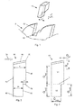
- Fig. 1 shows an exemplary cutting insert 10.
- the cutting insert 10 has substantially the shape of a cuboid, wherein the opposite surfaces need not be formed parallel to each other and wherein adjacent surfaces to each other need not be arranged at a 90 ° angle, but preferably an angle of 90 ° +/- 20 °, in particular 90 ° +/- 10 °.
- One of the surfaces has a shoulder or an offset v. Due to the offset v, there results a first surface in which the cutting insert has a thickness d and which is referred to as the rake face 30 and a second face which faces inwardly relative to the rake face 30 offset is that results in a thickness dv, which is less than the thickness d.
- the height of the cutting insert may preferably be 10 mm. Also preferably heights of 20 or up to 25 mm are used. Due to the relationships explained below, the advantageous properties of better heat dissipation can already form if a height of at least 6 mm is present. In conditions of use with a lower cutting speed, the height may be at least 4 mm.
- the height extends in the z-direction (see Fig. 1 ) and corresponds to the radial direction of the tool. In the upper region, the cutting tool is delimited in the z direction by the free surface 40 and downwards by the base surface 60.
- the depth of the cutting insert that is to say the extent in the x direction, can be 6 mm. The depth preferably corresponds to the length of the cutting edge 20.
- the depth of the tool is then between 3 and 10 mm when the tool is designed as a saw blade.
- the depth can be, for example, up to about 30 mm.
- the depth may decrease in a trapezoidal manner with a lesser extent in the z-direction. For example, if the depth at the cutting edge 20 is 6mm, it may decrease to 5mm toward the base 60 of the cutting insert.
- the cutting speed can be 50 - 100 m / s. In a steel processing, it is significantly lower at 100 to 200 m / min.
- the thickness of the cutting insert ie the extension in the y-direction may be about 4 mm in the upper region, ie at the cutting edge 20.
- the rake surface 30 may be substantially parallel with an opposing support surface 50, or in particular at an angle of +/- 10 °.
- the rake surface 30 ends with the offset v, wherein the offset is so positioned in the z-direction, ie in particular in the tool radial direction, that results in an upper region, which is in the vicinity of the cutting edge 20, and a lower region in the vicinity of the Floor space.
- the ratio of the lower region to the total height is preferably 0.3 in the z direction, the ratio generally being between 0.2 and 0.5.
- the rake surface 30 is completely non-bonded to the main body 2 of the tool. This also includes that no extension of the rake face directed in particular radially inwards (ie towards the tool axis of rotation) is provided, which lies approximately in the plane of the rake face 30 and which serves for the bonding and / or other connection to the base body 2 of the tool , In other words, there is no adhesive gap and / or no other connection plane which is directed in the extension of the rake face 30 radially inwardly.
- radial encompasses a range of up to +/- 40 ° to the geometrically exact radial direction.
- the cutting insert is used for cutting, which can be referred to in particular as drilling, milling or sawing.
- the material of the cutting insert has a high hardness.
- the material is designed impact and / or wear resistant. Use can find materials that have these properties as a solid material, or it can be a base coated.
- the coating may preferably be provided only in the region of the cutting edge 20.
- Suitable cutting materials are cutting ceramics, polycrystalline diamond (PCD), Cubic Boron Nitride (CBN), CVD diamond coatings and other CVD or PVD coatings or cermet.
- TiN or AlTiN coatings produced by means of PVD can be used.
- carbide can be used.
- CVD coatings are carried out at about 1000 ° C. For this reason, it is imperative that the coating is made prior to bonding the cutting inserts to the base body.
- Fig. 1 also shows the main body 2 of the tool 1, in which the cutting inserts 10 are glued. Since a saw blade is shown, the thickness of the body lying in the x-direction is slightly less than the depth of the cutting insert.
- the cutting insert is adhered to the base body 2 over four surfaces, namely, the support surface 50, the base 60, the offset surface 80, and a minor surface 70 that results across the width of the offset and the cutting insert depth.
- This secondary surface like the base surface, is oriented essentially perpendicular to the tool radial direction, that is to say the z-direction, whereby deviations of +/- 10 ° are preferably possible.
- the cutting insert is divided into two regions by a virtual separation line T in the xy plane, namely the upper volume V1 of thickness d and the lower volume V2 of thickness dv.
- the bonding in the area of the volume V2 is relevant for the fatigue strength of the bond.
- an adhesive gap in the 0.1 to 0.3 mm range is relevant for the holding surface 50, the base 60 and the offset surface 80.
- an adhesive based on an epoxy can be used as the adhesive.
- This may for example be a one-component adhesive, which is thermally cured.
- the strength may typically be in a range of -40 ° to 220 ° C or up to 250 ° C. When the upper temperature is reached, the strength does not drop abruptly to zero, but decreases successively, so that, for example, it can be allowed that the temperature temporarily rises above the stated upper limit, if the load is not particularly strong. In addition, it is important to pay attention to the type of load. Pressure loads can be better tolerated even at higher temperatures than, for example, tensile or shear loads. When bonding both the cutting insert 10 are wetted to the surfaces to be bonded, as well as the base body 2 with the adhesive.
- the cutting insert 10 When the cutting insert 10 is placed in its receptacle of the base body 2, so the cutting insert aligns in its recording due to capillary forces evenly in the y direction. With an automatic measuring and positioning device, the cutting insert is also positioned in the y-direction and moved in the x-direction until it is in its desired position. In addition, the cutting insert 10 is pressed by this device so deep in the negative z-direction until the cutting insert in this direction, so the tool radial direction is aligned. The positioning accuracy in these directions is 10 to 20 ⁇ m depending on the application. After the positioning of the cutting insert, it and its direct surroundings are heated, preferably inductively, so that partial hardening takes place for fixing the cutting insert at its desired position. After all cutting inserts have been fixed in this way, the tool 1 is placed in a curing oven and tempered there for about 30 minutes at about 150 ° C, whereby the adhesive hardens to its desired hardness.
- temperatures of 1000 ° C can occur at high cutting performance.
- High cutting performance results in particular in a combination of a high cutting speed and a high feed.
- the two most important causes of the high temperatures are the temperature generation during the material deformation of the chip during the cutting process and the sliding and rubbing of the chip along the chip surface 30. Part of this energy is dissipated via the chip. Another considerable part is directed into the cutting insert. This is done at areas adjacent to the cutting edge 20.
- Fig. 3 shows this heat entry zones Q a .
- the heat release takes place over all other surfaces of the cutting insert and is divided into the heat transfer to the main body 2 of the tool 1 and in the heat transfer to the remaining surfaces to the ambient air and / or a cooling medium. Since the latter heat transfer is not part of the Invention, it is not discussed in detail below and only the heat transfer Q out of the material in the main body 2 considered. This is dependent on the individual areas in Fig. 3 located.
- temperatures of 1000 ° C. can occur directly at the cutting edge 20.
- the adhesive of the cutting insert but can only withstand significantly lower temperatures.
- the cutting insert is designed as described above, in particular to ensure a permanent and secure bonding of the lower portion V2 that the entire cutting insert is securely held permanently.
- each cutting insert engages the workpiece only 5% or 10% of the time, depending on the actual working conditions.
- the duration of the heat input is thus only 5% or 10% of a tool revolution.
- the heat strives to spread as evenly as possible in the material of the cutting insert.
- the tool is designed in the vicinity of the cutting edge 20 with the thickness d. It is significantly higher than would be necessary due to the required strength and thus results in a relatively high volume V1, within which the heat can be distributed over the duration of a tool revolution. Due to this averaging already reduces the maximum temperature, which acts on the splices.
- the cutting insert with 10 mm has a greater height than would be necessary for the pure processing, so the bond and the bond strength.
- the height can be a maximum of 20 or 25 mm over the entire surface of the cutting insert temperature is continuously dissipated.
- the temperature decreases with a greater distance from the cutting edge 20.
- the cutting edge is glued to the base body via the surfaces designated by Q aus1 and Q aus2 . At each point of these surfaces, heat is released to the body. Although it flows steadily heat from the cutting edge 20, but at the base 60 and adjoining portions of the holding and offset surface is only a part of the cutting heat, so that there the heat load is reduced to the bond.
- the offset v of the offset surface 80 relative to the rake face 30 is used clarify is in Fig. 3 the virtual separation line T drawn.
- the heat flow within a material is proportional to the cross-sectional area.
- the cross-sectional area at the dividing line T and below is less than the upper area where the cutting insert 10 has the thickness d.
- the ratio of the areas of heat transfer to the base body 2, namely the ratio of (Q out of 2 + Q out of 3 + Q out of 4 ) / dv is significantly larger than the ratio of the heat transfer surface Q out of 1 / d.
- the heat from the lower region V2 is derived more strongly than can flow over the cross section T.
- the increase in heat in the lower region, ie the volume V2 is effectively limited, so that the maximum temperature of the bond is not exceeded even at high cutting performance.
- the heat load on the volume V2 is then reduced the more, the thinner the thickness dv.
- a small thickness dv is advantageous due to thermal cycling.
- the material of the base body 2 has a different temperature strain value than the material of the cutting insert 10. It can be approximated that the temperature of the volume V2 is identical to the temperature of the surrounding base body 2. Both, both the cutting insert will stretch at an elevated temperature in the y-direction. Due to the different thermal expansion values, a difference or a delta ⁇ of these values results. This delta ⁇ acts as a stress on the bonding at the surfaces Q out 2 and Q out 4 . Since this delta is proportional to the thickness dv, for low thicknesses dv in the lower region V2 of the cutting insert 10, lower thermal cycling stresses of the bonding of these surfaces Q aus2 and Q aus4 .
- Fig. 6 and Fig. 7 show another advantage resulting in reduced thickness dv of the lower portion of the cutting insert.
- Fig. 6 shows the force F1 acting on the cutting edge during a normal cutting movement. At the exit of the cutting edge from the Material, the force F1 goes back to zero immediately and due to elastic stresses in the material creates an opposing force F2. (please refer Figure 7 )
- the force F1 causes via the pivot point D1 a tilting force K1.
- a tilting force K1 is suitable for dislodging the cutting insert by tipping out.
- a tilting force K1 has a dotted line the case known from the prior art that the cutting insert has no offset in the lower region.
- a tilting force K1 'results This force K1 'has a higher proportion in the z direction. The larger this proportion in the z direction, the greater the risk that the bond dissolves over the multiplicity of loads. And thus causes the smaller force component of the K1 in the z-direction the advantage of better bonding.
- Fig. 7 shows the corresponding case with the oppositely directed force F2.
- the thickness dv is as small as possible.
- too small a thickness dv may be disadvantageous because a minimum thickness is necessary to absorb forces resulting from the cutting forces.
- the preferred method of bonding results in a minimum thickness dv.
- the chips Since the gap in the secondary surface 70 and the base body 2 is at an angle of at least 45 °, preferably 90 ° +/- 10 °, the chips would have to be redirected accordingly in their movement, for which there is no cause. Chips, which are derived along the chip surface 30, hit the corresponding material of the body and are there broken. Due to the offset v, they can not get into the adhesive gap between the offset surface 80 and the base body 2. Furthermore, the chips can not get into the gap between the auxiliary surface 70 and the base body 2, since this would require a significant deflection. The same effect arises also, albeit mitigated, at the in Fig. 8 shown embodiment.
- Fig. 4 shows three views of an alternative cutting insert.
- a phase 94 is arranged on both axially aligned surfaces 90 in the transition to the free surface 40.
- a further phase 30a is provided on the cutting edge 20, that is to say in the transition from the clamping surface 30 to the free surface 40.
- This phase 30a is not absolutely necessary and the above-explained advantages of the attachment of the cutting insert and influences on the temperature distribution arise regardless of whether a phase 30a is present or not.
- the chip slides along both the phase 30a and a portion of the rake face 30 adjacent to the phase 30a. For this reason, the phase is considered part of the rake face 30.
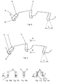
- Fig. 5 shows two sections of a saw blade 2 with and without glued cutting inserts 10.
- the diameter of the saw blade can be 100 cm and / or be equipped with at least 50 cutting inserts.
- Fig. 8 shows an alternative embodiment in which the offset surface is at an angle to the rake face.
- this angle can be between 30 ° and 60 °.
- the following advantages result in angular ranges of 10 ° to 80 °.
- offset surface is generally defined as being an area that has a misalignment or slope relative to the rake surface.
- the cutting insert 10 can be pivoted during the bonding in a corresponding receptacle of the base body 2. This pivoting action is through the left and middle cutting insert 10 of Fig. 8 clarified. In this case, the cutting insert is shown on the left on insertion into the main body and before bonding. After the cutting insert has been positioned in this way, it is pivoted so that it comes in the centered position in which it is aligned exactly. Thereafter, the adhesive is first partially cured by heat supply successive cutting insert for cutting insert and then the entire tool is cured.
- the cutting forces F1 act in such a way that when cutting the cutting insert tends to be pivoted further in the described holding direction. At high cutting loads and correspondingly high temperatures, the adhesive bond may eventually soften gradually, so that the maximum holding force can not be given. Due to the described geometry of the cutting insert can still be securely held in the base body 2.
- the surface 82 of the main body 2 is the adhesive surface with the offset surface 80 and is oriented radially inwardly, so that force components of the bond act as a compressive force in the radial direction of the centrifugal force.
- Fig. 8 Offset surface 80 and the rake surface 30 are immediately adjacent, so that both surfaces touch directly and no secondary surface exists.
- the corresponding contact line lies in the x-direction (see Fig. 1 ).
- the embodiment of the Fig. 9 combines the advantages of the embodiments of Fig. 1 to 7 with the embodiment of Fig. 8 ,
- the offset surface 80 has an offset to the rake surface 30, so that the transition of these surfaces results in a secondary surface 70, as has already been described in detail above.
- the 10a, 10b, 10c and 11a show alternative cutting inserts from the perspective of section AA of Fig. 9 , ie in the top view in the xz plane.
- the tool is designed as a saw. In positive and negative x-direction, the cutting insert protrudes beyond the base body 2.
- 10a and 10b show that the cutting edge 20 need not lie in the axial direction of the tool, but may be inclined. Phases 99 can be provided laterally on the cutting edge. The size of the phase can increase or decrease in the cutting direction.
- Fig. 11b shows a rotated by 90 ° side view of the embodiment, which in Fig. 11a is shown.
- the rake surface 30 does not have to be flat, but may include ridges or depressions.
- the rake surface 30 is understood to be the surface or surfaces of the cutting insert at which the chip can slide under normal working conditions.
- the rake face merges into the minor surface 70. This does not have to be inclined at a 90 ° angle to the rake face 30.
- On the secondary surface 70 preferably no slipping of chips takes place.
- the offset surface 80 is arranged, with which the bonding is realized.
- the cutting edge 20 is aligned so that it is aligned approximately in the direction of the tool longitudinal axis, wherein preferably an angular deviation of up to +/- 60 ° or in particular 45 ° may exist.
- the free surfaces 40 are provided substantially at the radially outwardly facing surfaces of the individual cutting inserts 10 from the point of view of the tool rotation axis.
- the cutting edge 20 lies in each case at the transition of the free surface 40 to the rake surface 30 or to the arranged on the rake surface 30 phase 30a.
- the support surface 50 and / or the offset surface 80 and / or the minor surface 70 and / or the base surface 60 are and are preferably oriented so that they do not lie in the plane of the tool cross section.
- the orientation "top” used in the description refers to a large value in the z direction (see Fig. 1 ) or radially outward.
- the dimensions and sizes of the cutting insert specified in the description and claims relate to a respective cutting insert with non-parallel opposing surfaces at the respective maximum distance in each radial, axial and / or tangential direction of the tool. Reference numerals are used identically in different embodiments, as long as the correspondingly designated surfaces have comparable functions.
Landscapes
- Engineering & Computer Science (AREA)
- Mechanical Engineering (AREA)
- Cutting Tools, Boring Holders, And Turrets (AREA)
- Drilling Tools (AREA)
- Milling Processes (AREA)
Applications Claiming Priority (1)
| Application Number | Priority Date | Filing Date | Title |
|---|---|---|---|
| DE102013220449.3A DE102013220449B4 (de) | 2013-10-10 | 2013-10-10 | Verfahren zur Herstellung eines spanabhebenden Werkzeugs |
Publications (1)
| Publication Number | Publication Date |
|---|---|
| EP2859977A1 true EP2859977A1 (fr) | 2015-04-15 |
Family
ID=51751910
Family Applications (1)
| Application Number | Title | Priority Date | Filing Date |
|---|---|---|---|
| EP20140187872 Withdrawn EP2859977A1 (fr) | 2013-10-10 | 2014-10-07 | Outil d'usinage par enlèvement de copeaux |
Country Status (2)
| Country | Link |
|---|---|
| EP (1) | EP2859977A1 (fr) |
| DE (1) | DE102013220449B4 (fr) |
Cited By (2)
| Publication number | Priority date | Publication date | Assignee | Title |
|---|---|---|---|---|
| US20140377021A1 (en) * | 2013-06-21 | 2014-12-25 | Albert Knebel Gmbh & Co. Kg Holding | Saw blade having a small saw tooth |
| US11103940B2 (en) * | 2016-06-28 | 2021-08-31 | Komet Group Gmbh | Metal-cutting machine tool |
Citations (7)
| Publication number | Priority date | Publication date | Assignee | Title |
|---|---|---|---|---|
| BE458205A (fr) * | ||||
| DE2803850A1 (de) * | 1978-01-30 | 1979-08-02 | Steinbearbeitungs Maschinenfab | Werkzeug fuer eine saegevorrichtung, insbesondere zum saegen von stein |
| DE9218759U1 (de) * | 1992-01-10 | 1995-04-27 | Richard Felde GmbH & Co KG, 42855 Remscheid | Kreissägeblatt für Holz- und Metallbearbeitung |
| JPH08289650A (ja) * | 1995-04-20 | 1996-11-05 | Miyaden:Kk | 刈払い機用のチップソー及びそのチップ |
| CN1887492A (zh) * | 2006-07-17 | 2007-01-03 | 陶娜 | 一种更换锯齿的锯片 |
| DE102010036874A1 (de) | 2010-08-05 | 2012-02-23 | Gühring Ohg | Spanabhebendes Werkzeug und Verfahren zu dessen Herstellung |
| DE202013102690U1 (de) * | 2013-06-21 | 2013-07-01 | Albert Knebel Gmbh & Co. Kg Holding | Sägeblatt mit kleinem Sägezahn |
Family Cites Families (5)
| Publication number | Priority date | Publication date | Assignee | Title |
|---|---|---|---|---|
| GB1373084A (en) | 1970-11-14 | 1974-11-06 | Ellis G A | Cutter teeth pro-provided with carbide tips |
| DE2505463A1 (de) * | 1975-02-10 | 1976-08-19 | Guhdo Werk Herbert Doerken | Zahn fuer spangebende werkzeuge |
| DE9217598U1 (de) | 1992-12-23 | 1993-03-04 | Unterwurzacher Patentverwertungsgesellschaft M.B.H., Kuchl | Zerkleinerungsscheibe |
| DE202005000994U1 (de) | 2005-01-21 | 2006-06-01 | Gühring, Jörg, Dr. | Spanabhebendes Werkzeug |
| DE102011012690A1 (de) * | 2011-03-01 | 2012-09-06 | Ake Knebel Gmbh & Co. Kg | Sägeblatt |
-
2013
- 2013-10-10 DE DE102013220449.3A patent/DE102013220449B4/de active Active
-
2014
- 2014-10-07 EP EP20140187872 patent/EP2859977A1/fr not_active Withdrawn
Patent Citations (7)
| Publication number | Priority date | Publication date | Assignee | Title |
|---|---|---|---|---|
| BE458205A (fr) * | ||||
| DE2803850A1 (de) * | 1978-01-30 | 1979-08-02 | Steinbearbeitungs Maschinenfab | Werkzeug fuer eine saegevorrichtung, insbesondere zum saegen von stein |
| DE9218759U1 (de) * | 1992-01-10 | 1995-04-27 | Richard Felde GmbH & Co KG, 42855 Remscheid | Kreissägeblatt für Holz- und Metallbearbeitung |
| JPH08289650A (ja) * | 1995-04-20 | 1996-11-05 | Miyaden:Kk | 刈払い機用のチップソー及びそのチップ |
| CN1887492A (zh) * | 2006-07-17 | 2007-01-03 | 陶娜 | 一种更换锯齿的锯片 |
| DE102010036874A1 (de) | 2010-08-05 | 2012-02-23 | Gühring Ohg | Spanabhebendes Werkzeug und Verfahren zu dessen Herstellung |
| DE202013102690U1 (de) * | 2013-06-21 | 2013-07-01 | Albert Knebel Gmbh & Co. Kg Holding | Sägeblatt mit kleinem Sägezahn |
Cited By (2)
| Publication number | Priority date | Publication date | Assignee | Title |
|---|---|---|---|---|
| US20140377021A1 (en) * | 2013-06-21 | 2014-12-25 | Albert Knebel Gmbh & Co. Kg Holding | Saw blade having a small saw tooth |
| US11103940B2 (en) * | 2016-06-28 | 2021-08-31 | Komet Group Gmbh | Metal-cutting machine tool |
Also Published As
| Publication number | Publication date |
|---|---|
| DE102013220449A1 (de) | 2015-04-16 |
| DE102013220449B4 (de) | 2022-01-05 |
Similar Documents
| Publication | Publication Date | Title |
|---|---|---|
| EP2601000B1 (fr) | Outil d'usinage par enlèvement de copeaux et procédé pour le produire | |
| EP2280797B1 (fr) | Fraise à queue | |
| EP1972399B1 (fr) | Fraise à tête sphérique, système d'outil doté d'une fraise à tête sphérique et méthode pour attacher une fraise à tête sphérique | |
| EP1931490B1 (fr) | Outil d'enlèvement de copeaux | |
| DE102010000640A1 (de) | Stirnfräser | |
| DE102013111596A1 (de) | Schaftfräser für warmfeste Superlegierungen | |
| EP3233339B1 (fr) | Outil d'usinage par enlèvement de copeaux | |
| EP2401106A1 (fr) | Outil de fraisage à disque et élément de coupe | |
| DE102008034784B4 (de) | Fräswerkzeug zum Fräsen faserverstärkter Kunststoffe | |
| DE102014015199A1 (de) | Messerkopf zur spanenden Bearbeitung von Werkstoffen und Messer hierfür | |
| DE102013220449B4 (de) | Verfahren zur Herstellung eines spanabhebenden Werkzeugs | |
| DE102006043616A1 (de) | Reibahle | |
| DE102005048691A1 (de) | Werkzeug und Verfahren zur Bearbeitung eines Werkstückes aus einem harten Material | |
| DE4220136C1 (de) | Spannsystem für Werkzeugmaschinen | |
| DE10129401B4 (de) | Maschinenreibahle | |
| DE102016111805A1 (de) | Spanabhebendes Maschinenwerkzeug, insbesondere Maschinenreibwerkzeug | |
| DE102015109432B3 (de) | Schneidperle für ein Sägeseil, Sägeseil und Verfahren zur Herstellung eines Sägeseils | |
| DE102005031988A1 (de) | Zerspanungswerkzeug | |
| DE102019117799B4 (de) | Zerspanungswerkzeug mit asymmetrischen Zähnen mit Schneidpartikeln | |
| DE102016000899A1 (de) | Schneidwerkzeug für die spanende Bearbeitung eines Werkstückes | |
| DE102016105847A1 (de) | Schneidkörper und Schneidwerkzeug | |
| EP1673192B1 (fr) | Alesoir | |
| DE102012005976A1 (de) | Keramische Schneidplatte zur zerspanenden Hartbearbeitung | |
| DE102005005213A1 (de) | Werkzeug zur Feinbearbeitung von Bohrungsoberflächen | |
| DE102008029619B4 (de) | Trennschleifscheibe zur Erzeugung eines breiten Schnittes |
Legal Events
| Date | Code | Title | Description |
|---|---|---|---|
| PUAI | Public reference made under article 153(3) epc to a published international application that has entered the european phase |
Free format text: ORIGINAL CODE: 0009012 |
|
| 17P | Request for examination filed |
Effective date: 20141007 |
|
| AK | Designated contracting states |
Kind code of ref document: A1 Designated state(s): AL AT BE BG CH CY CZ DE DK EE ES FI FR GB GR HR HU IE IS IT LI LT LU LV MC MK MT NL NO PL PT RO RS SE SI SK SM TR |
|
| AX | Request for extension of the european patent |
Extension state: BA ME |
|
| R17P | Request for examination filed (corrected) |
Effective date: 20150616 |
|
| RBV | Designated contracting states (corrected) |
Designated state(s): AL AT BE BG CH CY CZ DE DK EE ES FI FR GB GR HR HU IE IS IT LI LT LU LV MC MK MT NL NO PL PT RO RS SE SI SK SM TR |
|
| 17Q | First examination report despatched |
Effective date: 20180704 |
|
| STAA | Information on the status of an ep patent application or granted ep patent |
Free format text: STATUS: THE APPLICATION IS DEEMED TO BE WITHDRAWN |
|
| 18D | Application deemed to be withdrawn |
Effective date: 20190115 |